Gyrotropic Crystals as a Basis for Creation of Helical Polychromatic Singular Beams


Physics and Technology Institute, V.I. Vernadsky Crimean Federal University, Vernadsky Prospect 4, 295007 Simferopol, Russia
*
Author to whom correspondence should be addressed.
Photonics 2023, 10(9), 1044; https://doi.org/10.3390/photonics10091044
Submission received: 14 August 2023
/
Revised: 6 September 2023
/
Accepted: 12 September 2023
/
Published: 14 September 2023
(This article belongs to the Special Issue Optical Communication, Sensing and Network)
Abstract
:In this work, studies are carried out in the field of optical singular beams that have passed through gyrotropic crystals. We have experimentally shown that singular beams with a helical intensity distribution are formed when passing through a system of two gyrotropic crystals with opposite values of the gyration coefficient. It is shown that the system is capable of generating optical vortices with a double topological charge in one of the components of circular polarization when light propagates through two gyrotropic crystals.
1. Introduction
In modern singular optics, special attention is paid to beams carrying the so-called optical vortices and those carrying a topological charge [1]. In the mid-1990s, such beams in free space were obtained experimentally [2,3]. It was then that an intensive experimental study of singular beams began. Around the same time, it was discovered that rays with optical vortices carry angular momentum [4,5]. Particular interest in beams containing optical vortices has increased significantly due to the fact that such beams can be used to create optical tweezers and similar objects.
However, the creation of single optical vortices carried by paraxial beams of the Laguerre–Gauss and Bessel–Gauss types faces serious technical difficulties. The point is that the traditional method of obtaining optical vortices is based on light diffraction either on computer-synthesized holograms [2,3] or on spiral phase plates [6,7]. These methods are based on strict observance of the diffraction conditions near the phase singularity and are critical to the wavelength. In this case, special mention should be made of optical beams that have the property of Fourier invariance [8,9]. However, in [10,11,12], it was possible to avoid such stringent requirements for the formation of an optical vortex due to the processes of light propagation in a uniaxial anisotropic medium. It has been shown that a circularly polarized beam propagating along the optical axis of an anisotropic medium is capable of forming optical vortices on the axis with the same localization, regardless of the wavelength.
Traditional concepts of a linearly polarized paraxial beam passing along the optical axis of a uniaxial crystal suggest that at the exit from the crystal after passing through the polarizer, the beam forms an intensity distribution in the form of a Maltese cross [13]. This pattern is a distinctive feature of a uniaxial crystal.
From the point of view of polarization features, the conoscopic pattern arises as a result of the superposition of two circularly polarized beams carrying vortices with a double topological charge of the opposite sign. In fact, this picture is a field with perpendicular edge dislocations.
When the beam is tilted relative to the optical axis or when external perturbations are introduced, the double vortices leave the beam, and the structure of edge dislocations undergoes structural transformations. The bulk of theoretical and experimental studies [14,15] mainly concerns the study of the structure of conoscopic patterns arising in axial beams. Conoscopic carines are interference patterns in a converging polarized beam obtained in crossed polarizers, between which the anisotropic medium under study is located. The conoscopic pattern corresponding to the circular state of polarization on the input face of an anisotropic crystal is localized in the focal plane of the objective. However, it also has the shape of concentric rings, and near the beam axis there are four topological dipoles separated by bright stripes. Any disturbance of the axial extension is considered to be a perturbation of the conoscopic pattern. However, this process hides various transformations of polarization features caused by weak perturbations.
It should be noted that the studies [16,17,18] are devoted to the study of the structure of polarization features in low-order Laguerre–Gauss beams that arise after excitation of the crystal by linearly polarized light. The authors of these papers focused on linearly polarized beams. Their model is based on two linearly polarized beams carrying optical vortices (ordinary and extraordinary) propagating at slightly different angles.
As is known, uniaxial and biaxial crystals serve as basic elements for the generation of optical vortices embedded in various types of singular beams [19]. The most amazing feature of the crystal is the ability to create stable polychromatic vortices with high energy efficiency. In contrast to the method of computer holograms [20,21,22], the crystal forms a white vortex beam without any additional devices [23].
The purpose of this article is to consider another method that allows one to generate singular beams carrying screw edge dislocations and optical vortices using two gyroanisotropic crystals. Before considering the method of generating singular beams carrying optical vortices using two gyroanisotropic crystals, it is necessary to evaluate the influence of a gyrotropic crystal on the wave front.
2. Gyroanisotropic Crystals
First, it should be noted that a gyrotropic crystal is a space that does not only have linear birefringence (that is, space is able to transform circularly polarized light into linearly polarized, and vice versa), but also circular birefringence (that is, space is able to rotate linear polarization). Even in simple cases, electrical vector and magnetic vector are expressed in a complex way:
To estimate the effect of a gyrotropic crystal on a singular beam, we chose the Jones matrix method, which we have already used for anisotropic crystals in [19]. Consider the propagation of a beam through an element of a gyrotropic crystal along its optical axis. The optical axis coincides with the z axis. The input face of the crystal is located on the plane z = 0. A linearly polarized Gaussian beam is incident normally on the input face of the crystal. As was shown in [19], a Gaussian beam can be represented as a set of rectilinear rays distributed in space along a hyperboloid of revolution. Figure 1 shows one of these beams directed at the crystal at an angle to its optical axis. The birefringence axes are in the same plane as the optical axes and form an angle with the y-axis.
The beam passes through the element dz of the crystal. The beam polarization transformation can be written in matrix form:
where
and where is the number of layers in a crystal, is the phase difference between the ordinary and extraordinary components of the beam that has passed through a crystal of length d, is linear birefringence, and are values for the ordinary and extraordinary refractive indices, k is the wave number, is the full rotation (gyration) of the electric vector, and is the value for circular birefringence.
As the thickness of the crystal element tends to zero, , and at , we have:
where matrices are .
For the total length of the crystal, we have:
Define the form
Rewrite in the form:
where , and * signifies complex conjugation.
Refine the matrix . The matrix has its own values:
Write the equation for eigenvectors:
where and are the eigenvectors of the matrix . Then,
Compose from and the matrix , the columns of which are the vectors and :
Matrix , the inverse of matrix , has the form:
Further:
Using the matrix eigenvalue equation:
where and are the eigenvectors and eigenvalues of the matrix .
Rewrite the matrix in the form:
where . Expression (18) is called the generalized Jones matrix.
3. Transformation TE and TM Modes in a Gyrotropic Crystal
The above Matrix (18) describes the transformation of the polarization state of a beam propagating in a gyrotropic crystal. A linearly polarized Gaussian beam passing through a crystal undergoes structural changes. One example of such a change is shown in Figure 2.
At the same time, it is interesting to consider the transformation of the beam mode fields depending on their own polarization, which they had in a simple anisotropic crystal. As is known [16,17], such beams are TE and TM modes [24] with the following polarization state:
where is the complex amplitude of the paraxial beam with indices , .
The results of the action of the Matrix (18) on the fields TE and TM are shown in Figure 3. The straight lines of the TE and TM modes that can be observed on the input face of a gyrotropic crystal become twisted in a spiral, and with the opposite twist, as the beam propagates along the crystal.
The longer the crystal, the more the direction of the major semiaxis of the polarization vector twists. Moreover, the linear polarization becomes elliptical. Thus, the TE and TM modes are not eigenmodes of a gyrotropic crystal. To determine the intrinsic polarization of the beam, consider the characteristic equation:
It follows that the eigenvalues are:
Therefore, the eigenvectors of Matrix (18) have the form:
where .
The field structure of eigenmodes is a system of ellipses. Each of these ellipses has its own ellipticity and azimuth angle . Write the Stokes parameters using Expression (23). We receive:
Therefore, the azimuth angle of the major axis of the ellipse is:
The angle of ellipticity can be written as:
This is in connection with:
Define the ellipticity of the beam:
Given the very weak gyration of the crystal (which is the case for real crystals ) away from the axes, the ellipticity will be represented as:
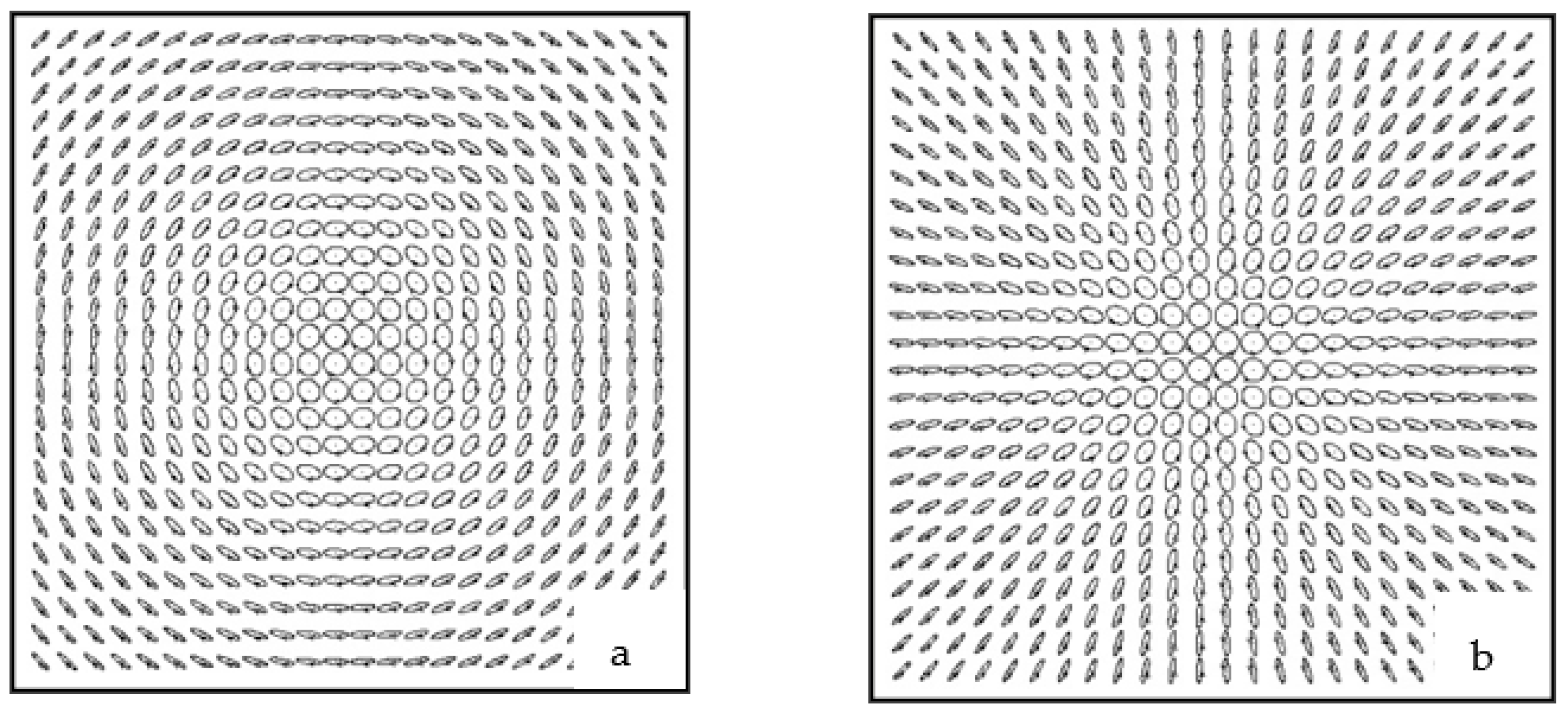
Beam eigenmodes in a simple gyrotropic crystal have a nonuniform distribution of polarization over the beam cross section. Their polarization components do not have phase singularities (except for the axial case). On the axes, the eigenfields are circularly polarized, as shown in Figure 4.
As we move away from the center (see Figure 4a,b), the ellipticity of the polarization state decreases until the light eventually becomes linearly polarized.
4. Propagation of a Beam through Two Gyroanisotropic Crystals
Consider the propagation of a beam through two gyrotropic crystals with different values of circular birefringence . The rest of the crystal parameters remain the same.
For this case, it is necessary to multiply two matrices [3] with the difference . After applying linear algebra, we have
The eigenvalues of Matrix (6) have the form
Thus, the eigenvectors can be represented as:
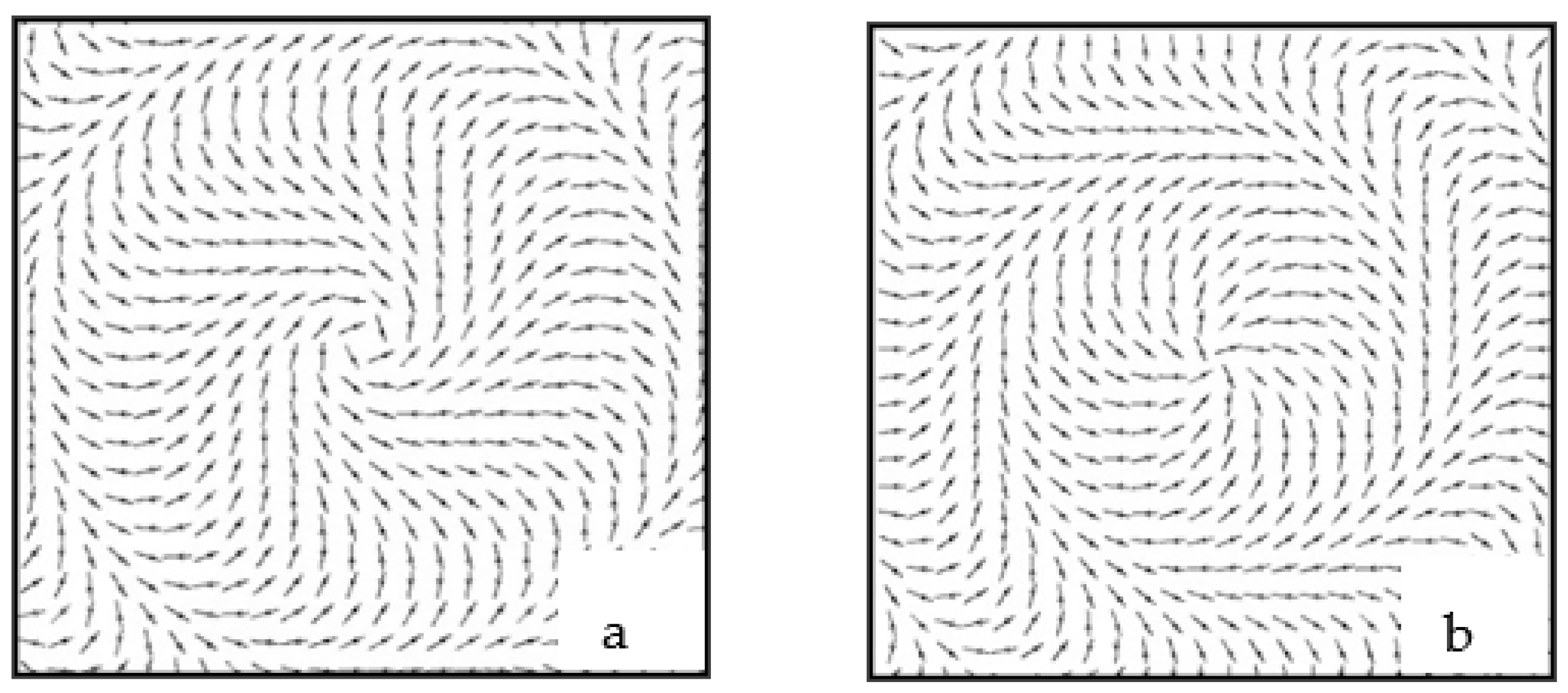
The elements of the column vector (34) are real values. Based on this, the fields are linearly polarized. The polarization distribution map data are shown in Figure 5.
Their structure near the optical axes looks like TE and TM modes in a simple anisotropic crystal, but far from the center there are significant differences. We call them pseudo-TE and pseudo-TM mods [24]. The intensity distributions of these fields have interesting features. Figure 6 illustrates the intensity distribution for differently polarized pseudo-TM mode components. While the component does not have any singularities, except for a simple zero on the axis, the component forms a new type of phase singularity——a double helical edge dislocation. Indeed, the phase singularity condition is , that is,
The first expression describes the double helix, while the second describes the distribution at the periphery. This complex spiral vortex beam is shown in Figure 6.
Figure 6.
Beams with self-polarization of the pseudo-TM mode in a double gyrotropic crystal: (a) and (b) components; (c) spiral vortex phase (, , ).
Figure 6.
Beams with self-polarization of the pseudo-TM mode in a double gyrotropic crystal: (a) and (b) components; (c) spiral vortex phase (, , ).

The first expression describes the double helix, while the second describes the distribution at the periphery. This complex spiral vortex beam is shown in Figure 7.
In contrast to the case of a single crystal, lines of equal phase have become double helixes, and the wave front in the vicinity of the singularity is an indirect helicoid. If we change the sign of the input polarization circulation, then the intensity distribution in the optical vortex will not change, but the direction of the phase helix twist will change. Although in conventional optical experiments such a helical distribution of lines of equal phase is not detected, it has an unexpected manifestation when a linearly polarized beam propagates through a double gyroanisotropic crystal, which can be represented as a set of circularly polarized beams with the opposite direction of rotation of the vector E, so that at the output, the field pattern can be represented in the form of two circularly polarized beams carrying optical vortices with opposite topological charges. Indeed, such a superposition detects the phase of the vortices so that, as a result, we obtain a quarter-fold intensity spiral. However, these features are characteristic only of their own rays. They can be partially “embedded” into the original light beam from a double crystal in the form of a superposition of eigenbeams.
5. Generate Polychromatic Helical Beams
The question is how to extract a beam with a pure helical edge dislocation from the combined beam after the crystal. The easiest way to achieve what you want is to launch a linearly polarized beam into a crystal, that is
Comparing Expressions (34) and (35), the y-component in Expression (36) describes the same helical edge dislocation as in Expression (34). Generally speaking, the images presented in Figure 8 have been known for quite a long time in crystallography as Airy spirals, and are used to distinguish right-handed and left-handed crystals. However, our path shows a way to create spiral singular beams. Thus, from Expression (35), it follows that the radius of the first ring dislocation can be found from the following condition: . Provided that the beam waist at the entrance face of the crystal is equal to , the contribution of the energy flux to the ring dislocation is negligibly small. The configuration of the spiral beam field is shown in Figure 8.
It should also be noted that this gives us the technical ability to generate polychromatic helical beams. To do this, you just need to focus polychromatic light into a crystal.
The images shown in Figure 9 are the result of a computer simulation of the process. Attention was drawn to the fact that the light source was like a completely black body—so that all rays have only a radial radius for all wavelengths. This means that our rays are spatially coherent.
6. Optical Vortices
The beams generated in a double gyroanisotropic crystal have another useful property—they can carry optical vortices. Indeed, let us pass a circularly polarized Gaussian beam through a double crystal. From a mathematical point of view, this means the following:
After passing through a quarter-wave plate, the field will take the form:
The polarizer cuts out the —component from the spiral vortex field. Thus, the intensity and interference distribution takes the form shown in Figure 10.
In fact, we have obtained an ordinary vortex with a double charge, similar to those that can be obtained on a simple anisotropic crystal [11,19,25].
Consider in more detail the mechanism of generation of a double topological charge by means of a uniaxial crystal. A typical map of the polarization distribution of a beam that has passed through an anisotropic medium and a polarization filter (a quarter-wave plate and a polarizer) is shown in Figure 11a. We see that right-hand circular polarization is located on the beam axis. This exceptional state of polarization surrounds a family of ellipses. A characteristic property of this family is the typical ordering of orientation directions of the major semiaxis of the ellipse. If we draw integral curves—lines tangent at each point to the semi-major axis—we will get a characteristic pattern of spirals (see Figure 11b). These integral curves are analogous to lines of force for a linearly polarized (at each point) electric or magnetic field. In this case, they represent the lines of force of the inhomogeneously polarized beam. Such a pattern of integral curves near the singular point is similar to the distribution of lines of equal curvature of the wave front near the wave caustics [26]. They are called umbilic points. In the future, we will keep this analogy, calling these patterns surrounding polarization singularities polarization umbilics [11,19,25].
According to the terminology of J. Nye [26], an umbilic is formed in the vicinity of a singular point called a C-point. In fact, in the general case, we should not be talking about points, but about lines of space. As in the scalar case, in the vector field, these lines are formed by the intersection of two surfaces. The intersection of the line by the observation plane forms a C-point. On the C-line, the field intensity, in the general case, does not vanish. The authors of [15,16,17,18,19] distinguish, in the form of characteristic features of the vector field, the so-called L-surfaces. On this surface, only linear polarization of partial waves exists. L-surfaces always cover C-lines and separate C-lines corresponding to opposite directions of polarization, circulation of circular polarization. If at the transition of C-lines the phase of the field changes abruptly by , then at the transition of the L-surface, the direction of circulation of the partial fields abruptly changes.
In our case, as shown in Figure 11a, the pattern of singularities is somewhat different. In the center of the picture is C—a point that is covered by L-line—as a result of a section of the observation plane’s C-line and L-surface; however, instead of the L-line, with the opposite direction of ellipticity, we see a characteristic C-line as a result of section C-plane surface. On the C-surface, light is circularly polarized. Thus, the overall picture of the vector field after a uniaxial crystal is presented as a set of C and L-surfaces nested into each other, which cover the central C-line. Such a difference in the classification introduced in [15,16,17,18,19] with the vector field we are studying after a uniaxial crystal is due to the fact that in these works, the structure of random stochastic fields, which arises as a result of laser beam scattering on random anisotropic inhomogeneities, is studied.
At the same time, we are interested in the process of beam passage through a spatially homogeneous anisotropic medium, in which field states with an unstable singularity structure are possible. As soon as a weak polarization perturbation is introduced into the beam, the picture changes dramatically. A quarter wave plate installed after the crystal can act as such a polarization perturbation.
It is necessary to point out some characteristic features of the picture obtained as a result of the action of the perturbation (see Figure 12). First of all, unstable singularities disappear. The unstable C-point in the center of the picture splits into two single C-points displaced along the beam . In the structure of the Figure 12, there are two more simple C-points located on the beam . These two singularities arose as a result of the splitting of the unstable C-line into four symmetrically located C-points: two shifted along the rays to the beam axis.
Two other singularities have shifted along the rays to the periphery. Now, the singularity distribution pattern is structurally stable to the effects of external perturbations.
To convert vector singularities into optical vortices, it is necessary to install a plate and a polarizer in a series after the crystal. The plate converts the circular polarization to linear polarization, while the polarizer, whose axis is properly oriented, suppresses linear polarization. As a result, zero electric field strength is formed on the beam axis. The occurrence of a phase singularity is easy to understand if we turn to the distribution map of the polarization state (see Figure 11). We will go around C—a point on the beam axis along a closed contour—and follow the rotation of the major semi-axis of the partial wave ellipse. A complete tour of the contour corresponds to the rotation of the axis of the polarization ellipse by .
Therefore, a change in the angle from to corresponds to a change in the phase of the wave , also from to . This means that in the vicinity of the beam axis, when passing along a closed contour, a phase difference runs up, which is typical for fields with phase singularities. In this case, such a singularity belongs to the left-hand circular polarization component of the field. A typical picture of a double helicoid near the axis shows the presence of a double topological charge of the vortex. The wave front at the periphery is cut by rings, and each ring corresponds to an unstable ring dislocation.
At the same time, the vortices obtained in anisotropic crystals are surrounded by numerous ring dislocations, while in our case, these dislocations are almost never observed. The degree of splitting of dislocations depends on the coefficient . The greater the gyration of the crystal, the less noticeable the dislocations, but at the same time, the coefficient decreases , so that in the final analysis, the spiral vortex beam can disappear under the condition in which the circular birefringence is much greater than the linear one.
7. Experimental Obtaining of Singular Beams in Gyroanisotropic Crystals
At present, our attention is most attracted to polychromatic singular beams. As a result, we have focused our efforts on the generation of helical edge dislocations embedded in polychromatic beams.
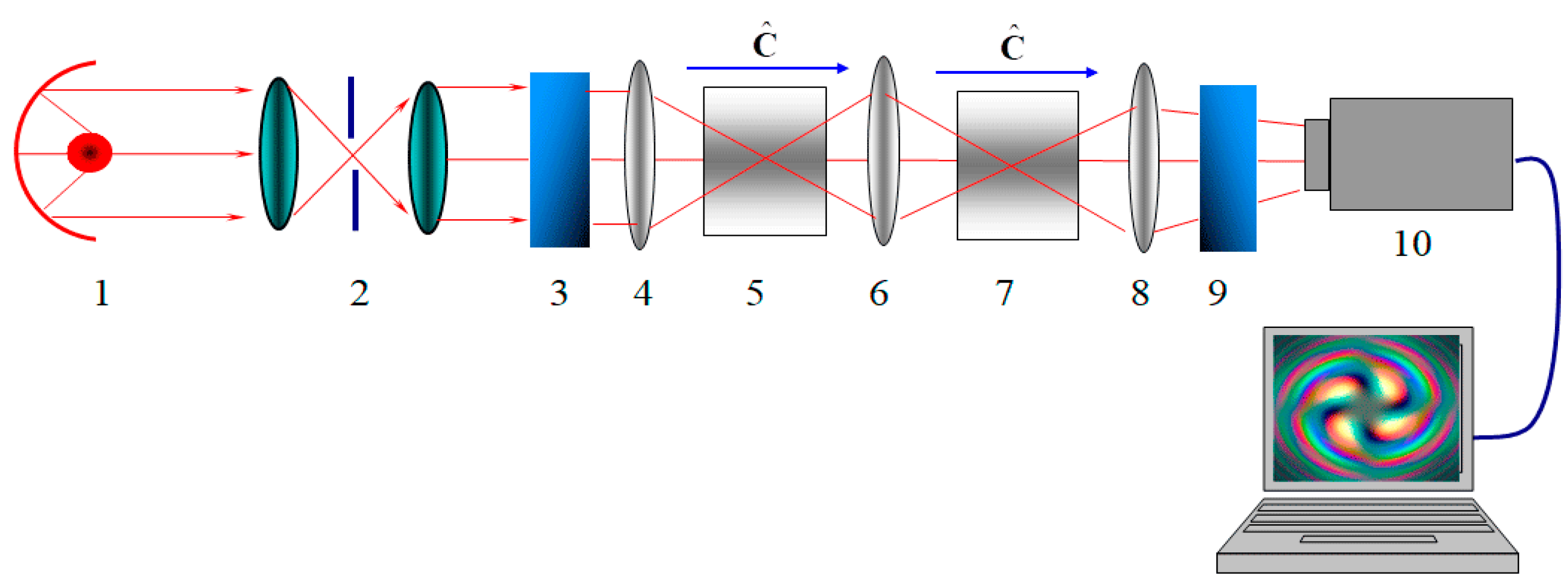
The scheme of the experimental setup is shown in Figure 13. The key element of the installation is a white light source, which is a halogen lamp equipped with a spherical mirror. The angular divergence of the beam after passing through the spatial lens filter becomes less than . The beam then passes through a polarizer to become linearly polarized.
After that, the beam is focused by a lens with a focal length of 3 cm into a LiNbO3 crystal. Next, we focus the beam again, but now into the SiO2 crystal. The optical axes of the crystals are directed along the beam axes. The beam image is projected onto the screen of a CCD camera and processed by a computer.
We considered the intensity distribution of the singular beam as a function of the direction of the polarizer axes .
Figure 14 shows typical images of a singular beam. When the angle is , a pure spiral vortex beam dislocation is embedded in the beam. It is important to note that the dislocations are not washed out in polychromatic light, but are seen as clear spiral lines with four branches. The method of generation of polychromatic singular spiral vortex beams described in this paper can be applied by other researchers to analyze the properties of spin and orbital angular momentum [5,9,22].
8. Conclusions
A type of monochromatic and polychromatic singular beams carrying helical edge dislocations and optical vortices has been theoretically and experimentally studied. Such beams can be created using natural objects—gyroanisotropic crystals. A linearly polarized monochromatic or polychromatic beam of light passing through two gyroanisotropic crystals with opposite signs of the gyration and polarization coefficients creates spiral vortex edge dislocations—also called Airy rings. The expressions that form the basis of the described phenomenon are written down. These expressions enable us to analyze various cases of the propagation of singular beams. As experimental objects, we used a system of two crystals: LiNbO3 and SiO2, whose optical axes are directed along the beam axes. The beam of light produced by a halogen lamp is transformed by this system in such a way that a polychromatic phase singularity with a clearly defined central spiral line is built into it.
The method described in this article can be applied by other researchers to analyze the properties of spin and orbital moments in free space [27,28], to analyze the shapes and properties of beams that carry a topological charge, to study anisotropic media [29,30], and to study the properties of topological charges [31,32,33,34,35,36] both in anisotropic media and in weakly turbulent atmospheric media.
The results obtained in this publication can be used in modern photonics, for example, to develop improved configurations of the shape and types of optical beams, to find states (C-lines and L-surfaces) of polarization of anisotropic media that cannot be created by other means, and to overcome any technical limitations associated with the improvement of design instruments and apparatus, including those for medical research.
Author Contributions
Conceptualization, Y.E. and A.R.; methodology, Y.E.; validation, Y.E. and A.R.; formal analysis, Y.E. and A.R.; investigation, Y.E. and A.R.; resources, Y.E. and A.R.; writing—original draft preparation, Y.E.; writing—review and editing, Y.E. and A.R.; supervision, Y.E.; project administration, Y.E. and A.R. All authors have read and agreed to the published version of the manuscript.
Funding
This research received no external funding.
Institutional Review Board
Not applicable.
Informed Consent Statement
Informed consent was obtained from all subjects involved in the study.
Data Availability Statement
The data presented in this study are available upon request from the respective author.
Conflicts of Interest
The authors declare no conflict of interest.
References
- Berry, M.V. Optical vortices evolving from helicoidal integer and fractional phase steps. J. Opt. 2004, 6, 259–268. [Google Scholar] [CrossRef]
- Soifer, V.A.; Golub, M.A. Laser Beam Mode Selection by Computer-Generated Holograms; CRC Press: Boca Raton, FL, USA, 1994; p. 215. ISBN 978-0-8493-2476-5. [Google Scholar]
- Basistiy, I.V.; Bazhenov, V.Y.; Soskin, M.S.; Vasnetsov, M.V. Optics of light beams with screw dislocations. Opt. Commun. 1993, 103, 422–428. [Google Scholar] [CrossRef]
- Allen, L.; Paget, M.; Babiker, M. The Orbital Angular Momentum of Light. Prog. Opt. 1999, 39, 291–333. [Google Scholar] [CrossRef]
- Bliokh, K.Y. Spatiotemporal Vortex Pulses: Angular Momenta and Spin-Orbit Interaction. Phys. Rev. Lett. 2021, 126, 243601. [Google Scholar] [CrossRef]
- Bryngdahl, O. Radial- and circular-fringe interferograms. J. Opt. Soc. Am. 1973, 63, 1098–1104. [Google Scholar] [CrossRef]
- Beijersbergen, M.W.; Coerwinkel, R.P.C.; Kristensen, M.; Woerdman, J.P. Helical-wavefront laser beams produced with a spiral phaseplate. Opt. Commun. 1994, 112, 321–327. [Google Scholar] [CrossRef]
- Kotlyar, V.V.; Kovalev, A.A.; Porfirev, A.P. Vortex Laser Beams, 1st ed.; CRC Press: Boca Raton, FL, USA, 2018; p. 418. [Google Scholar] [CrossRef]
- Kotlyar, V.V.; Kovalev, A.A.; Kalinkina, D.S.; Kozlova, E.S. Fourier-Bessel beams of finite energy. Comput. Opt. 2021, 45, 506–511. [Google Scholar] [CrossRef]
- Ciattoni, A.; Cincotti, G.; Palma, C. Circularly polarized beams and vortex generation in uniaxial media. J. Opt. Soc. Am. A 2003, 20, 163–171. [Google Scholar] [CrossRef]
- Volyar, A.V.; Egorov, Y.A.; Rubass, A.F.; Fadeeva, T.A. Fine structure of white optical vortices in crystals. Tech. Phys. Lett. 2004, 30, 701–704. [Google Scholar] [CrossRef]
- Athira, B.S.; Mukherjee, S.; Laha, A.; Bar, K.; Nandy, D.; Ghosh, N. Experimental observation of the orbital Hall effect of light through pure orbit–orbit interaction for randomly and radially polarized vortex beams. J. Opt. Soc. Am. B 2021, 38, 2180–2186. [Google Scholar] [CrossRef]
- Born, M.; Wolf, E. Principles of Optics; Pergamon Press: Pergamon, NY, USA, 1980; p. 836. ISBN 9781483103204. [Google Scholar]
- Vlokh, R.; Mys, O.; Romanyuk, M.; Girnyk, I.; Martunyuk-Lototska, I.; Czapla, Z. Optical Characterization of Organic-Inorganic [(CH2OH)3CNH3)]H2PO4 Crystals. Ukr. J. Phys. Opt. 2005, 4, 133–135. [Google Scholar] [CrossRef]
- Cincotti, G.; Ciattoni, A.; Sapia, C. Radially and azimuthally polarized vortices in uniaxial crystals. Opt. Commun. 2003, 220, 33–40. [Google Scholar] [CrossRef]
- Flossmann, F.; Schwarz, U.T.; Maier, M.; Dennis, M.R. Polarization Singularities from unfolding an optical vortex through a Birefringent Crystal. Phys. Rev. Lett. 2005, 95, 253901. [Google Scholar] [CrossRef]
- Flossmann, F.; Schwarz, U.T.; Maier, M.; Dennis, M.R. Stokes parameters in the unfolding of an optical vortex through a birefringent crystal. Opt. Express 2006, 14, 11402–11411. [Google Scholar] [CrossRef]
- Craciun, A.; Grigore, O.V. Superposition of vortex beams generated by polarization conversion in uniaxial crystals. Sci. Rep. 2022, 12, 8135. [Google Scholar] [CrossRef]
- Volyar, A.V.; Fadeeva, T.A.; Egorov, Y.A. Vector singularities of Gaussian beams in uniaxial crystals: Optical vortex generation. Tech. Phys. Lett. 2002, 28, 958–961. [Google Scholar] [CrossRef]
- Kazanskiy, N.L.; Soifer, V.A. Diffraction investigation of geometric-optical focusators into segment. Optik 1994, 96, 158–162. [Google Scholar]
- Soifer, V.A. Diffractive Nanophotonics and Advanced Information Technologies. Her. Russ. Acad. Sci. 2014, 84, 9–20. [Google Scholar] [CrossRef]
- Leach, J.; Padgett, M.J. Observation of chromatic effects near a white-light vortex. New J. Phys. 2003, 5, 154. [Google Scholar] [CrossRef]
- Volyar, A.V.; Abramochkin, E.G.; Akimova, Y.E.; Bretsko, M.V.; Egorov, Y.A. Fast oscillations of orbital angular momentum and Shannon entropy caused by radial numbers of structured vortex beams. Appl. Opt. 2022, 61, 6398–6407. [Google Scholar] [CrossRef]
- Brandão, P.A. Nonparaxial TE and TM vector beams with well-defined orbital angular momentum. Opt. Lett. 2012, 37, 909–911. [Google Scholar] [CrossRef]
- Ling, X.; Luo, H.; Guan, F.; Zhou, X.; Luo, H.; Zhou, L. Vortex generation in the spin-orbit interaction of a light beam propagating inside a uniaxial medium: Origin and efficiency. Opt. Express 2020, 28, 27258–27267. [Google Scholar] [CrossRef]
- Nye, J.F. Natural Focusing and Fine Structure of Light: Caustics and Wave; Institute of Physics Publishing: Bristol, UK, 1999; p. 328. ISBN 0750306106. [Google Scholar]
- Volyar, A.V.; Abramochkin, E.G.; Egorov, Y.A.; Bretsko, M.V.; Akimova, Y.E. Digital sorting of Hermite-Gauss beams: Mode spectra and topological charge of a perturbed Laguerre-Gauss beam. Comput. Opt. 2020, 44, 501–509. [Google Scholar] [CrossRef]
- Volyar, A.V.; Bretsko, M.V.; Akimova, Y.E.; Egorov, Y.A. Avalanche instability of the orbital angular momentum higher order optical vortices. Comput. Opt. 2019, 43, 14–24. [Google Scholar] [CrossRef]
- Wang, X.; Liu, Z.; Zhao, D. Nonparaxial propagation of elliptical Gaussian vortex beams in uniaxial crystal orthogonal to the optical axis. J. Opt. Soc. Am. A 2014, 31, 2268–2274. [Google Scholar] [CrossRef]
- Egorov, Y.; Rubass, A. Spin-Orbit Coupling in Quasi-Monochromatic Beams. Photonics 2023, 10, 305. [Google Scholar] [CrossRef]
- Kotlyar, V.V.; Stafeev, S.S.; Zaitsev, V.D.; Telegin, A.M.; Kozlova, E.S. Spin–Orbital Transformation in a Tight Focus of an Optical Vortex with Circular Polarization. Appl. Sci. 2023, 13, 8361. [Google Scholar] [CrossRef]
- Stafeev, S.; Zaitsev, V. Focusing fractional-order cylindrical vector beams. Comput. Opt. 2021, 45, 172–178. [Google Scholar] [CrossRef]
- Kovalev, A.A.; Kotlyar, V.V.; Telegin, A.M. Optical Helicity of Light in the Tight Focus. Photonics 2023, 10, 719. [Google Scholar] [CrossRef]
- Nalimov, A.G.; Kotlyar, V.V. Effect of Optical “Dipoles” on the Topological Charge of a Beam. Nanotechnol Russ. 2022, 17, 915–919. [Google Scholar] [CrossRef]
- Kotlyar, V.V.; Kovalev, A.A.; Stafeev, S.S.; Zaitsev, V.D. Index of the Polarization Singularity of Poincare Beams. Bull. Russ. Acad. Sci. Phys. 2022, 86, 1158–1163. [Google Scholar] [CrossRef]
- Nalimov, A.G.; Kotlyar, V.V. Topological charge of optical vortices in the far field with an initial fractional charge: Optical “dipoles”. Comput. Opt. 2022, 46, 189–195. [Google Scholar] [CrossRef]
Figure 1.
Scheme of beam propagation through a gyrotropic uniaxial crystal; longitudinal (a) A`B` and transverse (b) AB.
Figure 1.
Scheme of beam propagation through a gyrotropic uniaxial crystal; longitudinal (a) A`B` and transverse (b) AB.

Figure 2.
Field structure of a linearly polarized Gaussian beam (a) after passing through a gyrotropic crystal with , , ; (b) long-range order of the field , , .
Figure 2.
Field structure of a linearly polarized Gaussian beam (a) after passing through a gyrotropic crystal with , , ; (b) long-range order of the field , , .

Figure 3.
Transformation TE (a) and TM (b) of mode beams in a gyrotropic crystal: , , .

Figure 4.
Self-polarized beams (a) and (b).

Figure 5.
Self-polarization of the beam in a gyrotropic crystal: (a) pseudo-TE mode and (b) pseudo-TM mode .
Figure 5.
Self-polarization of the beam in a gyrotropic crystal: (a) pseudo-TE mode and (b) pseudo-TM mode .

Figure 7.
Intensity distribution (a) in the E(-) left circularly polarized component and phase distribution for the left (b) circularly and right (c) circularly polarized components.
Figure 7.
Intensity distribution (a) in the E(-) left circularly polarized component and phase distribution for the left (b) circularly and right (c) circularly polarized components.

Figure 8.
Intensity distribution in a spiral vortex beam in (a)—, (b)— components (, , ).

Figure 9.
Polychromatic spiral vortex beam obtained at different angles relative to the polarizer axes (, , ).
Figure 9.
Polychromatic spiral vortex beam obtained at different angles relative to the polarizer axes (, , ).

Figure 10.
Image of a double charged vortex. (a) Intensity profile, (b) phase.

Figure 11.
Distribution map of the polarization state (a) and directions of orientation of the major semiaxis of the ellipse (b) in the cross section of the fundamental Gaussian beam after passing through a uniaxial crystal.
Figure 11.
Distribution map of the polarization state (a) and directions of orientation of the major semiaxis of the ellipse (b) in the cross section of the fundamental Gaussian beam after passing through a uniaxial crystal.

Figure 12.
Distribution map of the polarization of the beam field that passed through an anisotropic crystal and a quarter-wave plate. The axes of the quarter-wave plate are oriented at an angle of to the coordinate axes.
Figure 12.
Distribution map of the polarization of the beam field that passed through an anisotropic crystal and a quarter-wave plate. The axes of the quarter-wave plate are oriented at an angle of to the coordinate axes.

Figure 13.
Scheme of the experimental setup: 1—halogen lamp; 2—spatial lens filter; 3,9—polarizers; 4,6,8—lenses; 5—LiNbO3 crystal; 7—SiO2 crystal; 10—CCD camera, —unit vector of optical axes.
Figure 13.
Scheme of the experimental setup: 1—halogen lamp; 2—spatial lens filter; 3,9—polarizers; 4,6,8—lenses; 5—LiNbO3 crystal; 7—SiO2 crystal; 10—CCD camera, —unit vector of optical axes.

Figure 14.
Scheme of the distribution of the light flux over the angular spectrum in the Bessel–Gauss beam (, , ).
Figure 14.
Scheme of the distribution of the light flux over the angular spectrum in the Bessel–Gauss beam (, , ).

Disclaimer/Publisher’s Note: The statements, opinions and data contained in all publications are solely those of the individual author(s) and contributor(s) and not of MDPI and/or the editor(s). MDPI and/or the editor(s) disclaim responsibility for any injury to people or property resulting from any ideas, methods, instructions or products referred to in the content. |
© 2023 by the authors. Licensee MDPI, Basel, Switzerland. This article is an open access article distributed under the terms and conditions of the Creative Commons Attribution (CC BY) license (https://creativecommons.org/licenses/by/4.0/).
Share and Cite
MDPI and ACS Style
Egorov, Y.; Rubass, A. Gyrotropic Crystals as a Basis for Creation of Helical Polychromatic Singular Beams. Photonics 2023, 10, 1044. https://doi.org/10.3390/photonics10091044
AMA Style
Egorov Y, Rubass A. Gyrotropic Crystals as a Basis for Creation of Helical Polychromatic Singular Beams. Photonics. 2023; 10(9):1044. https://doi.org/10.3390/photonics10091044
Chicago/Turabian StyleEgorov, Yuriy, and Alexander Rubass. 2023. "Gyrotropic Crystals as a Basis for Creation of Helical Polychromatic Singular Beams" Photonics 10, no. 9: 1044. https://doi.org/10.3390/photonics10091044
Note that from the first issue of 2016, this journal uses article numbers instead of page numbers. See further details here.