Article

Influence of Adhesive Bonding on the Dynamic and Static Strain Transfers of Fibre Optic Sensors

1
Avnir Energy, F-01150 Saint-Vulbas, France
2
Laboratoire Hubert Curien UMR 5516, Institut d’Optique Graduate School, CNRS, Université Jean Monnet Saint-Etienne, F-42000 Saint-Etienne, France
*
Author to whom correspondence should be addressed.
Photonics 2023, 10(9), 996; https://doi.org/10.3390/photonics10090996
Submission received: 17 July 2023 / Revised: 25 August 2023 / Accepted: 29 August 2023 / Published: 31 August 2023
(This article belongs to the Special Issue Editorial Board Members’ Collection Series: Photonics Sensors)

Abstract

:
The influence of the bonding procedure (the adhesive type, application procedure, etc.) on the static and dynamic strain transfers of bonded optical fibre sensors is studied theoretically and experimentally at room temperature. The achievable performances with four different types of adhesives (three urethane and one epoxy adhesive), and with different fibre types, are evaluated: acrylate-coated, polyimide-coated, and bare single-mode optical fibres. Static strain measurements, ranging from 20 to 200 µ strain, are performed using both fibre Bragg gratings (FBGs) and optical frequency domain reflectometry (OFDR), and are compared to reference strain-gauge measurements, and to the proposed analytical model, which is developed on the basis of stress equilibrium relations. This model is valid for bonding to all types of linear and elastic materials, as long as there is no sliding between the host material, the adhesive, and the optical fibre. The results agree between the analytical model and the experiments. Regarding the dynamic sinusoidal strain measurements, the studied dynamic range is from 10 to 100 Hz, and only the FBGs are tested. The results demonstrate that the sensitivities of strain sensors based on bonded uncoated fibres or bonded polyimide-coated fibres are comparable to those of strain gauges, and that it is possible to use bonded FBGs for precise dynamic strain measurements.

1. Introduction

Silica-based optical fibres are widely used as the sensitive elements of point or distributed strain sensors for structural health monitoring. Due to their numerous advantages, they can actually serve as a real alternative to strain gauges: they are small and lightweight, are insensitive to most electromagnetic perturbations, and can operate over a wide temperature range with appropriate coatings. Different interrogation schemes have been developed to allow wavelength- or/and time-multiplexed measurements. Furthermore, this technology offers the possibility of remote measurements far from the acquisition system [1,2], a crucial advantage for operation in severe environments in which the interrogators could not survive. A wide range of optical fibre strain sensors exist, from distributed sensors based on Rayleigh and Brillouin scattering [1,2], to point sensors, such as Fabry–Pérot cavities [3], long-period gratings (LPGs) [4,5], or fibre Bragg gratings (FBGs) [6,7,8]. This article focuses on static and dynamic strain measurements based on Rayleigh scattering and FBGs.
The architectures of fibre sensors for strain measurements are very diverse. For example, Matveenko et al. [9] and Luyckx et al. [10] have investigated the embedding of FBGs in composites to perform local internal strain measurements. Barrias et al. [11] have also studied embedded fibres, but in concrete beams, and using the distributed OFDR (optical frequency domain reflectometry) technique. While these embedded optical fibre sensors can give access to unique information inside a structure, they cannot be repaired or replaced if needed. In another way, Guo et al. [12] and Cheng et al. [13] proposed packaged structure FBG sensors, suitable for local surface strain measurements. Although these packaged sensors are reusable, and exhibit enhanced strain sensitivities compared to bare FBGs, their complex design and size—10 cm long for the one developed by Guo et al. [12]—are not suitable for all applications. Here, we focus on another integration method, wherein the optical fibres are directly bonded on the surface of the object to be monitored. This method, which is less costly and easier to implement, is actually the subject of many studies [14,15,16,17,18,19,20,21]. In this context, the literature suggests various approaches to setting up analytical models that describe the static strain transfer mechanism between the material of interest and the bonded optical fibre sensor. The model remains the same for FBG and OFDR measurements. In [14,15,20], the authors proposed analytical models based on the calculation of the stress equilibrium relation [22], while in [16,17], the analytical studies are based on the shear lag model [23]. Contrary to the others, Liang et al. [15] have included the viscoelastic properties of adhesives, considering a standard linear solid model [24]. Nevertheless, we observed from these studies that favouring the viscoelasticity of adhesive in the model does not have a decisive impact on the consistency between the analytical results and experiments. Moreover, the finite elements method (FEM) has been exploited in order to study the static strain transfer phenomenon between a host material and the fibre core [17,18,19,21], and has shown a good agreement with analytical models.
Overall, analytical models, FEM, and experiments agree on the importance of the coating properties and the adhesive length and thickness on the fibre-sensing performance. In this paper, a revisited analytical model of a strain transfer mechanism based on the previous work by Liang et al. [15] is described. Additionally, static strain experiments at room temperature using FBG and OFDR techniques are performed, studying optical fibres with different coatings, bonded on aluminium beams, using different adhesives. Then, the results are compared with the analytical model, and with strain-gauge measurements. Finally, the strain transfer efficiency for the dynamic strain is experimentally studied using only FBGs, again at room temperature, to ensure that the bonded fibres are adapted to dynamic measurements.
Our results show that strain sensors based on FBGs and OFDR can perform as well as a strain gauge, and that the removal of the fibre coating allows for an increase in the sensitivity of the sensor. These results are validated via the analytical model, too. Bonded FBGs can also be used to monitor dynamic processes, as their responses do not change as a function of the frequency.

2. Analytical Model

The perfect strain transfer between the material being monitored and the sensitive part of the optical fibre strain sensor is essential to obtaining reliable measurements describing the material response. In this way, setting up an analytical model can provide a better understanding of the strain transfer phenomenon, and could allow for the maximisation of the sensor sensitivity.

2.1. Implementation of the Analytical Model

The analytical model described in this article is based on [15]. In our work, the model does not consider the viscoelasticity of the adhesive, but was adapted for an uncoated fibre, a single-coated fibre, and a double-coated fibre. The mechanical model is based on a layered stacking of the host material, the adhesive, the coating (which can be single, double, or absent), the cladding, and the core.
The following assumptions have also been made in this model:
  • All materials are linear and elastic;
  • There is no sliding at the interfaces, so the layers are perfectly bonded together;
  • The host material, which in our case will be aluminium, experiences a uniform longitudinal strain;
  • The core and cladding are considered as a single unit, as they share the same mechanical properties.
The model is, therefore, valid regardless of the host material, as long as the first three assumptions can be applied.
As described in Figure 1, considering a single-coated fibre, when the host material is subjected to longitudinal strain, it deforms by Umat, whereas the fibre core and cladding deform by only Ufibre. The huge difference between Umat and Ufibre is explained by the high elasticity of the adhesive and coating layers, which partly absorb the strain energy of the host material. This difference can be calculated using the following formula:
U m a t x U f i b r e x = Δ U c o a t + Δ U a d h = H h r c o a t + r f i b r e H h γ c o a t x , y d y + H h H γ a d h x , y d y
where rcoat is the coating radius, rfibre is the radius of the fibre (i.e., {core + cladding}), γcoat is the coating shear strain, γadh is the adhesive shear strain, h is the adhesive bondline thickness between the host material and the optical fibre, and H is the total adhesive bondline thickness. The two shear strain values are obtained via the application of stress equilibrium relations [22] to a small segment of both layers, and considering them as linear. We obtain:
γ c o a t x , y = E f i b r e 2 G c o a t · h + r c o a t H + y · d ε f i b r e ( x ) d x
and,
γ a d h x , y = E f i b r e G f i b r e · r c o a t 2 D h · D y H + 2 π r c o a t H h y · d ε f i b r e ( x ) d x
where Efibre is the fibre Young’s modulus, Gfibre and Gcoat are, respectively, the fibre and the coating shear moduli, Ɛfibre is the fibre strain, and D is the bonding width. Then, by substituting Equations (2) and (3) into Equation (1), we obtain, for the single coating fibre:
U m a t x U f i b r e x = 1 ξ 2   d ε f i b r e x d x
where:
1 ξ 2 = r c o a t 2 r f i b r e 2 4   G c o a t + h   r c o a t 4   G a d h   ·   1 + 2   π   r c o a t D ·   E f i b r e
Applying the same reasoning to a double-coated fibre, and an uncoated fibre, this last value is equal to:
1 ξ 2 = r s o f t _ c o a t 2 r f i b r e 2 4   G s o f t _ c o a t + r h a r d _ c o a t 2 r s o f t _ c o a t 2 4   G h a r d _ c o a t                                                                                     + h   r h a r d _ c o a t 4   G a d h   ·   1 + 2   π   r h a r d _ c o a t D ·   E f i b e r
for a double-acrylate-coated fibre, where rsoft_coat and rhard_coat are the soft- and hard-coating radius, and Gsoft_coat and Ghard_coat are the soft- and hard-coating shear moduli, and:
1 ξ 2 =   h   r f i b r e 4   G a d h   ·   1 + 2   π   r f i b r e D ·   E f i b e r
for an uncoated fibre.
Then, by differentiating Equation (4) with respect to x, we obtain the following differential equation:
d ² ε f i b r e ( x ) d x ² ξ 2 · ε f i b r e ( x ) = ξ 2 · ε m a t
To solve this equation, the boundary conditions are such that the strain transfer is zero on the unbonded parts of the fibre. Thus, we have:
ε f i b r e x = ε m a t · 1 c o s h ( ξ · x ) c o s h ( ξ · L 2 )
where L is the bonding length, and Ɛmat is the strain experienced in the host material.
In this article, the investigated optical fibres were either double-acrylate-coated fibres, mono-layer polyimide-coated, or uncoated. All fibres have a pure silica core and a fluorine-doped cladding, and they were all manufactured by EXAIL [25], allowing their use in radiation-rich environments [26]. Moreover, the choice of these fibres was guided by knowledge of their optical and mechanical characteristics. These values were used as input parameters for all the modelling procedures, and are listed in Table 1.
Figure 2 illustrates the simulated strain transfer efficiency profile along the core of a bonded double-acrylate-coated fibre, a polyimide-coated fibre, and an uncoated fibre, when the host material is deformed by Ɛmat. It shows the strong influence that the bonding length L, and the coating, have on the sensor sensitivity.
Finally, as the experimental strain measurements shown in Section 4.1 and Section 4.2 were averaged on the bonding length, we also averaged the strain field expressed in (9):
ε ¯ f i b r e = ε m a t · 1 2 ξ · L   t a n h ( ξ · L 2 )
In conclusion, the length L, the width D, and the thickness h of the bond, as well as the shear modulus of the coating and the adhesive, appear to be the parameters that need to be adjusted to improve the efficiency of the strain transfer. However, as we will see below, not all of these parameters have the same impact on the strain transfer efficiency.

2.2. Influences of Parameters on the Strain Transfer

Figure 3a,b show the impact of the geometrical parameters on the strain transfer efficiency, and Figure 3c,d show the impact of the mechanical parameters.
From these simulations, we can conclude that, compared to the bonding length, the adhesive bondline thickness h between the host material and the fibre has very little influence on the strain transfer, and that the bonding width D has no impact. Regarding the mechanical parameters, for a double-acrylate-coated fibre, the impact of the shear modulus of the soft acrylate coating on the strain transfer efficiency is very high. However, we cannot act directly on its value without a direct collaboration with the fibre manufacturer. On the other hand, we could more easily act on the shear modulus of the adhesive, in order to increase the strain transfer efficiency. However, given the very low shear modulus of the soft acrylate coating, the efficiency of the transfer as a function of the shear modulus of the adhesive converges very quickly towards its maximum. With a polyimide-coated fibre and an uncoated fibre, this convergence occurs less quickly, so the choice of the right adhesive can be crucial. Finally, as the impacts of the hard coating shear modulus of a double-acrylate-coated fibre, and the coating shear modulus of a polyimide-coated fibre do not influence significantly the strain transfer efficiency, they have not been represented in Figure 3.

3. Materials and Method

3.1. Optical Fibres and Fibre Bragg Gratings (FBGs)

We used 3 mm long Type II FBGs for our experiments. They were written through the fibre coatings via the point-by-point technique, using a Pharos IR-femtosecond laser and the harmonic generator HIRO @515 nm from Light Conversion. The inscription parameters included a pulse width of 190 fs, a laser energy of 70 µJ, and a ×40 objective with a numerical aperture of 0.75. They were inscribed either through the double-acrylate or polyimide coating, as described in Table 1. In addition, all FBGs were thermally treated for 15 h at 80 °C, so that unstable photoinduced refractive index contribution was erased.

3.2. Optical Fibres Bonding

3.2.1. The Adhesives Used and the Bonding Protocol

The strain transfer has been experimentally studied using four different adhesives, differing in terms of their chemical nature and Young’s modulus. As this latter parameter is of interest for our study, the adhesives were chosen to cover a wide range of Young’s moduli. Details of each of these adhesives can be found in Table 2.
Optical fibres were bonded to aluminium beams that had been carefully prepared in order to ensure a perfect bond between the two entities, and guarantee the validity of the second hypothesis, on which the analytical model is based (Section 2.1). The cleaning process incorporates:
  • A coarse clean with a degreasing soap;
  • Cleaning with an ethanol solution to remove ink marks and any other dirt;
  • A large-area mild etching, using a phosphoric-acid solution;
  • A local-area sanding step, to promote glue adherence;
  • A large, and then localised and intensive cleaning, using the phosphoric-acid solution to remove metal residues caused by the sanding;
  • A large, and then localised and intensive neutralisation, using an ammonia-based solution.

3.2.2. Bonding for FBG Measurements

FBGs were bonded, as described in the previous section, to aluminium beams using the four different adhesives, over a length of 11.4 ± 0.8 mm. According to Figure 2, a bonding length of 10 mm ensures a 100% strain transfer efficiency, at least for the polyimide-coated and the uncoated fibres. Table 3 shows the combination of beam, adhesive, and optical fibre used in each experiment.
Finally, strain gauges (CEA-06-032UW-120 from Micro-Measurement, Malvern, PA, USA) were glued on each sample using the X280 adhesive, so that the strains measured with FBGs could be compared to the strain-gauge measurements.

3.2.3. Bonding for OFDR Measurements

OFDR measurements were only performed using polyimide-coated fibres. Indeed, as we will see below, the FBG results showed that acrylate-coated fibres exhibit a poor performance, and that uncoated fibres are very fragile.
A single aluminium beam (280 × 25 × 2 mm3) was prepared, as described in paragraph 3.2.1, and a polyimide-coated optical fibre was bonded using the four adhesives, each over a length of 5 cm. The chosen length allowed us to study a longer length than that used for bonding FBGs, and enabled us to obtain a deformation distribution profile along the bonded fibre, exploiting the high spatial resolution of the OFDR. Two fibres were bonded on one side of the beam, and two others on the other side. In addition, a strain gauge was bonded to one side of the beam using the X280 adhesive.
The uncertainties regarding the bonding, the aluminium beam, and the position and orientation of the fibres were estimated via preparing other samples, but using the same adhesive on each. These measured uncertainties were added to the experimental results.

3.3. Static Strain Experiment

Static strain experiments were carried out using a tensile testing machine (AGX-V from Shimadzu, Kyoto, Japan), and applying static forces from 100 to 350 N to each sample (Figure 4). In this tensile configuration, the strain field is uniform along the aluminium samples.
During testing, the Bragg wavelength evolutions were recorded through an FBG interrogator, the Gator from PhotonFirst (Alkmaar, The Netherlands), at a sampling frequency of 19 kHz, in the spectral range between 1520 and 1540 nm. The Bragg wavelength evolutions were converted into strain variations, using the strain sensitivity coefficient of 1.2 pm/µε [6,8]. Spectral shift measurements were recorded through an optical backscatter reflectometer, OBR 4600 from Luna, working at 1550 nm, with a 10 mm gauge length, and a 1 mm sensor spacing. For the conversion into strain variations, the strain sensitivity used was 0.77 ppm/µε [31]. As was shown for the OFDR, the strain sensitivity does not change significantly (less than 1%) for the uncoated or coated fibres. Finally, the strain-gauge static measurements were obtained using an extensometer quarter bridge, the P-350AF from Vishay.
The tests were repeated three times, and all results were averaged, to improve the graph’s readability. Thus, all the graphs presented in this article represent averaged experimental values, and their standard deviations as uncertainties.

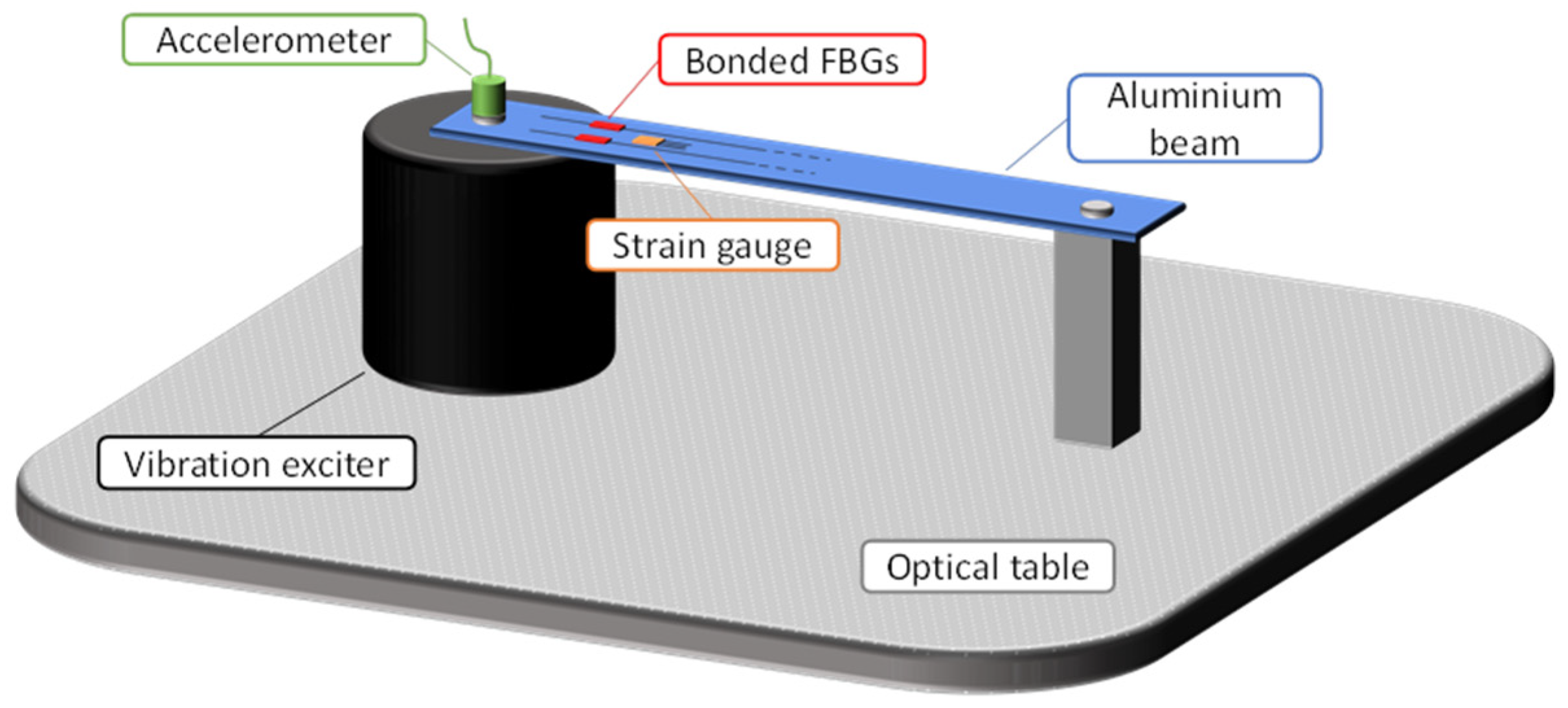
3.4. Dynamic STRAIN Experiments

In the dynamic experiments, aluminium beams were embedded on both sides: one side was screwed to a vibration exciter (Type 4809 from Brüel & Kjær, Naerum, Denmark), and the other side was screwed to a mechanical piece, linked with an optical table (Figure 5). In this way, the natural frequency of the beam was sufficiently far away (>100 Hz) to be able to only study the bonded FBG behaviour, as the beam response remained flat in the studied [10:100] Hz frequency range. The FBGs were glued close to an embedded side, as it is in these areas that the deformations in the beam are greater. Finally, because of the too-slow acquisition rate of the OFDR (lower than 0.2 Hz), it was not possible to study the dynamic strain transfer using this method.
An accelerometer (352C33 from PCB Piezotronics, Depew, NY, USA) fixed in the axis of the vibration exciter allowed us to record the applied acceleration to the aluminium beam, through the data acquisition system LAN-XI from Brüel & Kjær, and the associated software BK Connect. Additionally, as for the static experiments, the FBG data were recorded through the Gator interrogator system, at a sampling frequency of 19 kHz.
Experimentally, the dynamic tests consisted of applying a sinusoidal displacement of constant amplitude to the beam, at frequencies from 10 to 100 Hz. Four experiments were carried out, with four different constant displacements: 0.028 mm, 0.055 mm, 0.085 mm, and 0.14 mm. These displacement values were chosen in accordance with the performance of the vibration exciter, which had a 4 mm displacement limit and a 44.5 N force limit (Figure 6). These performances led to a maximum achievable acceleration of:
a m a x = F l i m i t m e + m s a m p l e = 44.5 0.06 + 0.015 594   m / s 2
where Flimit is the maximum force the exciter can provide, me is the mass of the exciter moving element, and msample is the mass of an aluminium sample. Using this maximal acceleration, a limit frequency flimit, above which the vibration exciter will no longer be able to provide sufficient force to maintain a displacement of 4 mm, can be defined. This limit is equal to:
f l i m i t = 1 2 π a m a x d m a x = 1 2 π 594 0.004 61   H z
After this frequency limit, the maximum possible displacement dmax decreases with increasing frequency, following the function:
d m a x = a m a x ( 2 π · f ) 2 = 594 ( 2 π · f ) 2 ,           w i t h   f > f l i m i t
According to Figure 6, a larger displacement could have been applied to the sample but was not, as we had no prior knowledge of the behavior of the bonded fibres.

4. Results and Discussion

This section is divided into three parts. The first and second parts focus on the experimental results of the static tests, and their comparison with the analytical model established in Section 2. The first part pertains to the measurements obtained from the FBGs, while the second part pertains to the measurements obtained from the OFDR. Finally, the last part discusses the dynamic measurements performed on the bonded FBGs.

4.1. Static Strain Study on the Bonded FBGs

4.1.1. Experimental Results

The experimental results for the bonded FBGs are shown in Figure 7. This figure reviews the strain measured for the polyimide-coated, uncoated, and double-acrylate-coated FBGs, bonded with each of the adhesives, as a function of the strain gauge measurement. The results were obtained through repeating each experiment three times, and calculating the means and standard deviations. Several conclusions can be drawn from these results:
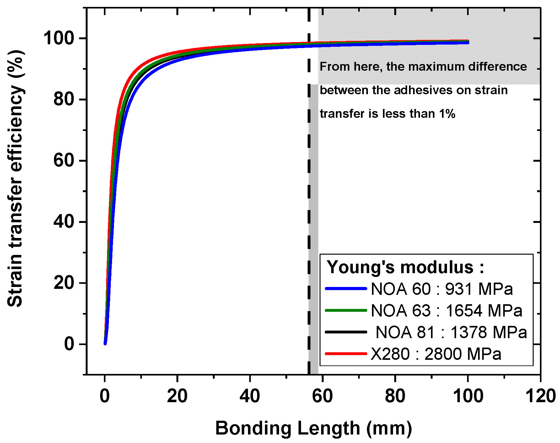
  • Firstly, the various adhesives transfer the deformation differently from the tensile specimen to the FBGs. As the bonding length has a huge influence on the strain transfer (Figure 2), and as this length is experimentally challenging to control, due to the various adhesive viscosities, the relative efficiency of the adhesive changes from one fibre to the other. This hypothesis will be verified via comparison with the analytical model in the next section.
  • Secondly, we can see that the gratings written in the double acrylate-coated fibres are poorly sensitive to deformation in the aluminium sample. This is attributed to the high elasticity of these coating materials.
  • Finally, we can state that bonded Bragg gratings inscribed on uncoated or polyimide-coated fibres are very sensitive to strain, and that uncoated gratings give similar or even better results than the strain gauges. For example, in Figure 7b, the FBG written on an uncoated fibre bonded with the NOA63 adhesive measured 176.5 ± 9.4 µ strain, as the strain gauge measured 167 µ strain, and the theoretical value obtained via Hooke’s law is 178 µ strain.
As mentioned at the beginning of Section 3.3, in pure tensile configuration, the strain field is uniform along the specimen, except close to the embedment. It can be seen that the strain gauges, bonded to different aluminium beams and in different positions, provide similar strain measurements for Figure 7a,c. The strain measurements shown in Figure 7b are higher, but this can be explained by the narrower width of the aluminium beam (Table 3). However, by multiplying the strains measured via the gauges by the width of their host aluminium beam, we can compare all the gauges together. Figure 8 presents these results, showing that the gauges, when not co-positioned, measure similar strains. Thus, the tensile specimens do, indeed, experience uniform strain fields, and the co-positioning of FBGs and strain gauges is not essential in our study.

4.1.2. Comparison with the Analytical Model

Figure 9 compares the experimental results to the analytical model outputs. The latter were obtained using the physical quantities given in Table 1 and Table 2, and considering the exact experimental bonding lengths and widths. The adhesive bondline thickness h is not possible to control or measure without the destruction of the samples. However, as the adhesive bondline thickness has little influence on the efficiency of strain transfer, according to the analytical model (Figure 3b), we therefore assumed that it was equal to 0.1 mm.
The analytical model corresponds quite well to the experiments, even though we can see some discrepancies. These can indicate inaccuracies between the geometrical and mechanical parameters used as inputs into the model, and the real parameters. These discrepancies are particularly noticeable on the double-acrylate fibre. This is explained by the uncertainty in the value of the Young’s modulus (and, therefore, the shear modulus) of the soft acrylate coating, which, according to the literature, can vary between 1 MPa [27] and 4 MPa [17]. The results from the analytical model are extremely sensitive to this uncertainty, as shown in Figure 3b, with the efficiency of the strain transfer increasing from 10.4% to 30.4% as Young’s modulus increases from 1 to 4 MPa (or the shear modulus increases from about 0.3 MPa to 1.3 MPa). The results of the model were calculated using each of these two extreme values from the literature, and we can see that the experimental results range between the two analytical results, demonstrating the consistency of the model.

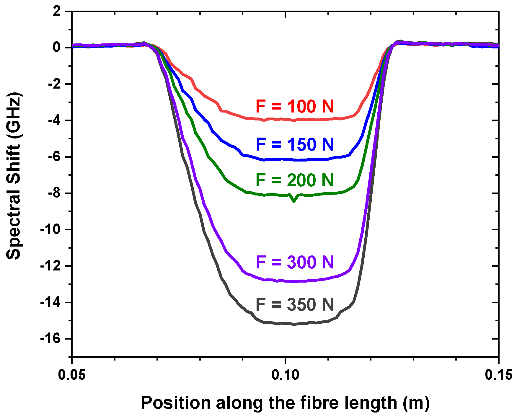
4.2. OFDR Static Strain Study

Experimental Results

As briefly discuss in Section 3.2.3, the uncertainties regarding the bonding, the aluminium beam, and the position and the orientation of the fibres were experimentally estimated through bonding 5 cm of polyimide fibre at four points on either side of the beam, using the same adhesive, and testing the sample with the tensile machine. One of these measurements is represented in Figure 10, where the uncertainties were estimated using the NOA 60 adhesive. The results from the four bonded areas were averaged, and a dispersion was calculated. In this way, we find that the bonding, the aluminium beam, and the position and the orientation of the fibres induce 15% of the error in the OFDR strain measurements. This error, which exceeds the experimental repeatability error, is represented in the results shown in Figure 12.
Figure 11 shows the spectral shift profile observed along a polyimide-coated fibre. Using the strain sensitivity coefficient of a fibre interrogated via OFDR, as defined in Section 3.3, we obtained a strain profile, of the opposite sign, similar to the spectral shift profile, itself comparable to the theoretical profiles illustrated in Figure 2, with a gradual increase and decrease in the strain sensitivity of the fibre. The average strains were then calculated for each deformation level, to obtain the results shown in Figure 12.
Figure 12 shows the strains measured via the bonded polyimide-coated fibre as a function of the stress applied to the tensile test specimen. To each of the results, the 15% measured uncertainty has been added, in the form of an error bar. In these results, we were able to highlight a zone in which all the adhesives behaved in the same way. We can observe that the strain gauge measurements correspond well with this highlighted area.
The results from the analytical model are also shown in Figure 12. It appears that the analytical model gives us almost-identical deformation responses for all adhesives, to within 0.12 µ strain. This result agrees with the experimental results, and can be explained by the fact that, after a certain bonding length, the Young’s modulus of the adhesives no longer has an impact, as the transfer is almost perfect (Figure 13).

4.3. Dynamic Strain Experiences of the Bonded FBGs

Figure 14 reports the frequency response function (FRF), defined as the ratio between the strain measured via the FBGs, and the acceleration applied to the aluminium specimen, as a function of the excitation frequency, obtained for each fibre coating and each adhesive. Each of these curves is the average of the ratio between the measured strain and the applied acceleration of the four experiments performed at different displacements, between 0.028 mm and 0.14 mm. As constant displacements were applied, i.e., accelerations increasing with frequency, all the FRFs decreased linearly with frequency. We do not observe any irregular behaviour in these results, and we can, therefore, conclude that, up to 100 Hz, the strain transfer from the specimen to the bonded FBG remains unchanged. Finally, we observed a difference in the sensitivity of the measurements between the different optical fibre coatings and the different adhesives, as demonstrated by the static tests and the analytical model.

5. Conclusions

Through this combined experimental and theoretical study, it has been shown that the use of polyimide-coated fibres and uncoated fibres should be prioritised to ensure reliable strain measurements through the FBG or OFDR techniques. Nevertheless, uncoated fibres turned out to be very fragile and, for long-term structural health monitoring, the polyimide-coated fibre appears to be the best choice, as it offers almost the same sensitivity. Concerning FBGs written in acrylate-coated fibres, they display a very weak strain sensitivity. Yet, we could exploit them to measure large strains, which polyimide-coated fibres could not resist. However, this would entail the calibration of the bonded acrylate-coated FBG, and the determination of the limit of acrylate adhesion. The experiments and analytical model have also proven that the bonding length is essential to ensuring the most perfect possible strain transfer, and that, below a ~50 mm bonding length, the Young’s modulus of the adhesive needs to be maximised for polyimide-coated and uncoated fibres.
Then, it was demonstrated that the bonded optical fibre sensors were functional over a dynamic range from 0 to 100 Hz. The precautions concerning bonding and coatings should be the same as those taken for static applications.
Further research is required, to study the impact of ageing on the strain transfer efficiency, particularly in relation to the other constraints (temperature and/or radiation) of the harsh environments for use in which sensors made using fluorine-doped optical fibres are very attractive.

Author Contributions

Conceptualisation, E.M., A.M. and C.L.; methodology, E.M., A.M., N.P., T.L.G. and C.L.; formal analysis, C.L.; writing—original draft preparation, C.L.; writing—review and editing, E.M., A.M. and S.G.; supervision, E.M., A.M., S.G., T.L.G., N.P. and J.C. All authors have read and agreed to the published version of the manuscript.

Funding

This research received no external funding.

Institutional Review Board Statement

Not applicable.

Informed Consent Statement

Not applicable.

Data Availability Statement

The data supporting the findings of this study are available from the corresponding authors upon reasonable request.

Conflicts of Interest

The authors declare no conflict of interest.

References

  1. Bao, X.; Chen, L. Recent Progress in Distributed Fiber Optic Sensors. Sensors 2012, 12, 8601–8639. [Google Scholar] [CrossRef] [PubMed]
  2. Hartog, A.H. An Introduction to Distributed Optical Fibre Sensors; Series in Fiber Optic Sensors; CRC Press: Boca Raton, FL, USA; Taylor & Francis Group: Abingdon, UK, 2017; ISBN 978-1-4822-5957-5. [Google Scholar]
  3. Rao, Y.-J. Recent Progress in Fiber-Optic Extrinsic Fabry–Perot Interferometric Sensors. Opt. Fiber Technol. 2006, 12, 227–237. [Google Scholar] [CrossRef]
  4. Vengsarkar, A.M.; Lemaire, P.J.; Judkins, J.B.; Bhatia, V.; Erdogan, T.; Sipe, J.E. Long-Period Fiber Gratings as Band-Rejection Filters. J. Light. Technol. 1996, 14, 58–65. [Google Scholar] [CrossRef]
  5. James, S.W.; Tatam, R.P. Optical Fibre Long-Period Grating Sensors: Characteristics and Application. Meas. Sci. Technol. 2003, 14, R49–R61. [Google Scholar] [CrossRef]
  6. Ferdinand, P. Capteurs à fibres optiques à réseaux de Bragg. Mes. Mécaniques Dimens. 1999, 6735, 1–24. [Google Scholar] [CrossRef]
  7. Hill, K.O.; Meltz, G. Fiber Bragg Grating Technology Fundamentals and Overview. J. Light. Technol. 1997, 15, 1263–1276. [Google Scholar] [CrossRef]
  8. Kashyap, R. Fiber Bragg Gratings; Optics and Photonics; Academic Press: San Diego, CA, USA, 1999; ISBN 978-0-12-400560-0. [Google Scholar]
  9. Matveenko, V.P.; Shardakov, I.N.; Voronkov, A.A.; Kosheleva, N.A.; Lobanov, D.S.; Serovaev, G.S.; Spaskova, E.M.; Shipunov, G.S. Measurement of Strains by Optical Fiber Bragg Grating Sensors Embedded into Polymer Composite Material. Struct. Control Health Monit. 2018, 25, e2118. [Google Scholar] [CrossRef]
  10. Luyckx, G.; Voet, E.; Lammens, N.; Degrieck, J. Strain Measurements of Composite Laminates with Embedded Fibre Bragg Gratings: Criticism and Opportunities for Research. Sensors 2010, 11, 384–408. [Google Scholar] [CrossRef]
  11. Barrias, A.; Casas, J.R.; Villalba, S. Application Study of Embedded Rayleigh Based Distributed Optical Fiber Sensors in Concrete Beams. Procedia Eng. 2017, 199, 2014–2019. [Google Scholar] [CrossRef]
  12. Guo, Y.; Kong, J.; Liu, H.; Hu, D.; Qin, L. Design and Investigation of a Reusable Surface-Mounted Optical Fiber Bragg Grating Strain Sensor. IEEE Sens. J. 2016, 16, 8456–8462. [Google Scholar] [CrossRef]
  13. Cheng, Y.; Lu, X.; Gong, Y.; Wu, Y.; Rao, Y. Derrick Safety Monitoring System Based on Fiber Bragg Grating Strain Sensors. Photonic Sens. 2013, 3, 237–240. [Google Scholar] [CrossRef]
  14. Ansari, F.; Libo, Y. Mechanics of Bond and Interface Shear Transfer in Optical Fiber Sensors. J. Eng. Mech. 1998, 124, 385–394. [Google Scholar] [CrossRef]
  15. Liang, M.; Chen, N.; Fang, X.; Wu, G. Strain Transferring Mechanism Analysis of the Surface-Bonded FBG Sensor. Appl. Opt. 2018, 57, 5837. [Google Scholar] [CrossRef] [PubMed]
  16. Her, S.-C.; Huang, C.-Y. The Effects of Adhesive and Bonding Length on the Strain Transfer of Optical Fiber Sensors. Appl. Sci. 2016, 6, 13. [Google Scholar] [CrossRef]
  17. Wan, K.T.; Leung, C.K.Y.; Olson, N.G. Investigation of the Strain Transfer for Surface-Attached Optical Fiber Strain Sensors. Smart Mater. Struct. 2008, 17, 035037. [Google Scholar] [CrossRef]
  18. Floris, I.; Sangiorgio, V.; Adam, J.M.; Uva, G.; Rapido, M.; Calderón, P.A.; Madrigal, J. Effects of Bonding on the Performance of Optical Fiber Strain Sensors. Struct. Control Health Monit. 2021, 28, e2782. [Google Scholar] [CrossRef]
  19. Duck, G.; Renaud, G.; Measures, R. The Mechanical Load Transfer into a Distributed Optical Fiber Sensor Due to a Linear Strain Gradient: Embedded and Surface Bonded Cases. Smart Mater. Struct. 1999, 8, 175–181. [Google Scholar] [CrossRef]
  20. Shen, W.; Wang, X.; Xu, L.; Zhao, Y. Strain Transferring Mechanism Analysis of the Substrate-Bonded FBG Sensor. Optik 2018, 154, 441–452. [Google Scholar] [CrossRef]
  21. Li, W.Y.; Cheng, C.C.; Lo, Y.L. Investigation of Strain Transmission of Surface-Bonded FBGs Used as Strain Sensors. Sens. Actuators Phys. 2009, 149, 201–207. [Google Scholar] [CrossRef]
  22. Hejazi, F.; Chun, T.K. Advanced Solid Mechanics: Simplified Theory: Simplified Theory, 1st ed.; CRC Press: Boca Raton, FL, USA, 2021; ISBN 978-1-00-314682-7. [Google Scholar]
  23. Dillard, D.A. Fundamentals of Stress Transfer in Bonded Systems. In Adhesion Science and Engineering; Elsevier: Amsterdam, The Netherlands, 2002; pp. 1–44. ISBN 978-0-444-51140-9. [Google Scholar]
  24. Meidav, T. Viscoelastic Properties of the Standard Linear Solid. Geophys. Prospect. 1964, 12, 80–99. [Google Scholar] [CrossRef]
  25. Available online: https://www.exail.com/ (accessed on 11 July 2023).
  26. Girard, S.; Kuhnhenn, J.; Gusarov, A.; Brichard, B.; Van Uffelen, M.; Ouerdane, Y.; Boukenter, A.; Marcandella, C. Radiation Effects on Silica-Based Optical Fibers: Recent Advances and Future Challenges. IEEE Trans. Nucl. Sci. 2013, 60, 2015–2036. [Google Scholar] [CrossRef]
  27. Pillon, J.; Louf, F.; Boiron, H.; Rattier, M.; Peter, E.; Boucard, P.-A.; Lefèvre, H.C. Thermomechanical Analysis of the Effects of Homogeneous Thermal Field Induced in the Sensing Coil of a Fiber-Optic Gyroscope. Finite Elem. Anal. Des. 2022, 212, 103826. [Google Scholar] [CrossRef]
  28. Ismardi, A.; Sugandi, G.; Lizarna, M.A. Design and Simulation of Double Planar Spring Based on Polyimide for Electrodynamic Vibration Energy Harvesting. J. Phys. Conf. Ser. 2019, 1170, 012061. [Google Scholar] [CrossRef]
  29. HBM. Available online: https://www.hbm.com/fr/ (accessed on 11 July 2023).
  30. NOA. Available online: https://www.norlandprod.com/adhesiveindex2.html (accessed on 11 July 2023).
  31. Boiron, H.; Pillon, J.; Peter, E.; Robin, T.; Villedieu, T.; Morana, A.; Girard, S.; Boukenter, A.; Marin, E.; Lefèvre, H. Optical Fiber Strain and Temperature Coefficients Determination Based on Rayleigh-OFDR. In Optical Fiber Sensors Conference 2020 Special Edition; Optica Publishing Group: Washington, DC, USA, 2021; p. T3.42. [Google Scholar]
Figure 1. Mechanical model for strain transfer analysis.
Photonics 10 00996 g001
Figure 2. The simulated strain transfer efficiencies along a bonded fibre for different bonding lengths, from 3 to 100 mm. The results were obtained considering (a) a double-acrylate-coated fibre, (b) a polyimide-coated fibre, and (c) an uncoated fibre. For these simulations, Young’s moduli of the first soft coating and the second hard coating of the double-acrylate fibre are, respectively, equal to 1 MPa and 1150 MPa, the Young’s modulus of the adhesive is 2800 MPa, and the width and thickness of the adhesive are 4 mm and 0.1 mm, respectively.
Photonics 10 00996 g002
Figure 3. Modelling of the strain transfer efficiency as a function of the geometrical parameters: adhesive width D (a), and adhesive bondline thickness h (b), and the mechanical parameters: adhesive shear modulus Gadh (c), and soft acrylate coating shear modulus Gsoft_coat (d), for a bonded double-acrylate-coated fibre, a polyimide-coated fibre, and an uncoated fibre. The parameters used for the simulation were: L = 20 mm; h = 0.1 mm; D = 10 mm; Gsoft_coat = 0.3 MPa; Gadh = 1000 MPa.
Photonics 10 00996 g003
Figure 4. (a) The force levels applied with the tensile machine to (b) the aluminium beam, fitted with bonded fibres and a strain gauge.
Photonics 10 00996 g004
Figure 5. Schema of the experimental setup.
Photonics 10 00996 g005
Figure 6. The maximum displacement that the vibration exciter can provide, according to its displacement and force performance limits as a function of the frequency. The experimentally applied displacements are also represented.
Photonics 10 00996 g006
Figure 7. Strain measured via the bonded FBGs written in (a) a polyimide-coated fibre, (b) an uncoated fibre, and (c) a double-acrylate-coated fibre, as a function of the strain measured via the strain gauges.
Photonics 10 00996 g007
Figure 8. The experimental strains measured via strain gauges multiplied by the width of their host aluminium beam, as a function of the tensile force applied to the beam.
Photonics 10 00996 g008
Figure 9. The experimental and analytical strains of the bonded FBGs written in (a) polyimide-coated fibres, (b) uncoated fibres, and (c) double-acrylate-coated fibres, as a function of the strain applied to the host material (some analytical data overlap). For the double-acrylate-coated fibres, the analytical solutions were calculated twice: the first time with Esoft_coat = 1 MPa, and the second time with Esoft_coat = 4 MPa.
Photonics 10 00996 g009
Figure 10. The experimental results of the determination of errors due to the position and orientation of the fibre, bonding, and beam, when a polyimide-coated fibre is bonded on an aluminium beam over 5 cm, using the NOA 60 adhesive. The dispersion of experimental measurements can be perfectly approximated with a relative error of 15%.
Photonics 10 00996 g010
Figure 11. The experimental spectral shift profile observed through OFDR measurements along a polyimide-coated fibre bonded over 5 cm to an aluminium beam using the NOA 81 adhesive.
Photonics 10 00996 g011
Figure 12. Strain measured via the four bonded polyimide-coated fibres, and via the strain gauge as a function of the stress applied to the tensile specimen; the results from the analytical model are also shown, in dotted lines (all overlapping).
Photonics 10 00996 g012
Figure 13. The analytical results showing the strain transfer efficiencies as a function of the bonding length, for the different Young’s moduli of the adhesives, for a polyimide-coated fibre.
Photonics 10 00996 g013
Figure 14. The frequency response function (FRF) of the double-acrylate-coated, polyimide-coated and uncoated FBGs bonded with the adhesive (a) NOA60, (b) NOA63, (c) NOA81 and (d) X280, when subjected to dynamic excitations, with constant displacements, from 10 to 100 Hz.
Photonics 10 00996 g014
Table 1. Optical fibres mechanical and geometrical properties (from [17,27,28]).
Uncoated FibrePolyimide FibreDouble-Acrylate Fibre
Core + cladding
Radius (µm)62.662.3562.6
Young’s modulus (MPa)72,00072,00072,000
Poisson ratio0.170.170.17
First Coating
Radius (µm)-79.495
Young’s modulus (MPa)-25004 (Ref. [17])
1 (Ref. [27])
Poisson ratio 0.170.498
Second Coating
Radius (µm)--122.5
Young’s modulus (MPa)--1000 (Ref. [17])
1150 (Ref. [27])
Poisson ratio 0.368
Table 2. Adhesives properties.
AdhesiveIntended forChemical NatureYoung’s Modulus (MPa)
X280 [29]Gauge bondingEpoxy2800
NOA 63 [30]OpticUrethane1654
NOA 81 [30]OpticUrethane1378
NOA 60 [30]OpticUrethane931
Table 3. Details of the combination of beams, adhesives, and fibres.
Aluminium BeamOptical Fibre CoatingAdhesive
ItemDimension
1180 × 23.75 × 1.2 mm3Double-acrylateNOA 81
Double-acrylateX280
2180 × 23.75 × 1.2 mm3Double-acrylateNOA 60
Double-acrylateNOA 63
3180 × 23.75 × 1.2 mm3PolyimideNOA 81
PolyimideX280
4180 × 23.75 × 1.2 mm3PolyimideNOA 60
PolyimideNOA 63
5180 × 22.50 × 1.2 mm3UncoatedNOA 81
UncoatedX280
6180 × 22.50 × 1.2 mm3UncoatedNOA 60
UncoatedNOA 63
Disclaimer/Publisher’s Note: The statements, opinions and data contained in all publications are solely those of the individual author(s) and contributor(s) and not of MDPI and/or the editor(s). MDPI and/or the editor(s) disclaim responsibility for any injury to people or property resulting from any ideas, methods, instructions or products referred to in the content.

