Second-Order Sidebands and Group Delays in Coupled Optomechanical Cavity System with a Cubic Nonlinear Harmonic Oscillator


1
Department of Physics, College of Science, Shanghai University, Shangda Road 99, Shanghai 200444, China
2
School of Optoelectronic Engineering, Guilin University of Electronic Technology, Guilin 541004, China
*
Author to whom correspondence should be addressed.
Photonics 2024, 11(3), 256; https://doi.org/10.3390/photonics11030256
Submission received: 18 January 2024
/
Revised: 8 March 2024
/
Accepted: 11 March 2024
/
Published: 12 March 2024
(This article belongs to the Special Issue Levitated Optomechanics)
Abstract
:The generation of second-order sidebands and its associated group delay is an important subject in optical storage and switch. In this work, the efficiency of second-order sideband generation in a coupled optomechanical cavity system with a cubic nonlinear harmonic oscillator is theoretically investigated. It is found that the efficiency of second-order sideband generation can be effectively enhanced with the decrease in decay rate of optomechanical cavity, the increase in coupling strength between two cavities and the power of probe field. The slow light effect (i.e., positive group delay) is also observed in the proposed optomechanical cavity system, and can be controlled with the power of control field.
1. Introduction
Cavity optomechanics is an important field that combines optics and mechanics. It focuses on the interaction between the light in a resonant cavity and the cavity mirror for mechanical vibration through the radiation pressure of light [1]. This interaction can be used on macroscopic gravitational wave detectors or microscopic scanning electron microscopy cantilevers. Due to its important research value in quantum communication and quantum computing [2] and ultrasensitive force measurement [3], cavity optomechanics has received considerable attention. Recent experiments have proved the possibility of cooling the mechanical oscillator to the quantum ground state in a cavity optomechanical system [4,5], which enables us to explore many nonlinear optical phenomena in optomechanical systems [6,7,8], such as the non-classical correlations between phonons and single photons [9], entanglement between mechanical and optical resonators [10,11], parametric normal-mode splitting [12,13,14], and mechanical compression state below zero point fluctuation [15,16,17]. In addition, electromagnetic induced transparency (EIT) effect has been widely discussed in quantum optics. It refers to the phenomenon that a medium composed of three-level or multi-level atoms becomes transparent to weak detection fields under the action of a strong driving electromagnetic field [18,19,20,21]. EIT has potential applications in enhancing nonlinearity [22], realizing fast light and slow light [23], quantum storage [24], and light switching [25]. The optomechanically induced transparency (OMIT), an analogue of EIT, can be reached in cavity optomechanical systems [19,26,27]. The basic mechanism of OMIT is the dissipative interference between the detection field photons and the upconversion sideband photons generated by the anti-Stokes process in the cavity optomechanical system, thus resulting in an adjustable transparent window of the detection light in the resonance region that should have been strongly absorbed.
The slow light effect based on OMIT has attracted considerable attention in recent years [20,28,29,30,31,32], which resulted in the anomalous dispersion of the system at the transparent window. OMIT has become a very important path for delaying, slowing down, and storing light signals. The second-order or higher-order sidebands can be generated in the cavity optomechanical system through the quantum operation of OMIT [33,34,35]. The generation of second-order sidebands [35] is a classic optical nonlinear phenomenon. When the control field and detection field are incident on an optomechanical system, the optomechanical interaction generates photons at the second-order sidebands. It has been demonstrated that the generation of the second-order sideband can improve the accuracy in charge and micro mass measurements [36,37,38].
However, most studies on the OMIT and second-order sidebands in cavity optomechanical systems are conducted with linear mechanical oscillators [19,27,33,37,39]. The neglect of the nonlinearity of mechanical oscillators can be attributed to its inherent weak nonlinearity. The cubic nonlinearity and Duffing quartic nonlinearity (i.e., fourth-order nonlinearity) are two typical nonlinearities of mechanical oscillators [40,41,42]. In recent years, it has been demonstrated that the weak nonlinear strength of mechanical oscillators can be significantly enhanced, for example, by engineering the material and geometrical effects of mechanical oscillators [43], introducing the electrostatic actuation [43], coupling with a low-dimensional auxiliary system [44], and using the chemical bonding force [42]. The enhanced nonlinearity of mechanical oscillators provides the opportunity to study various interesting phenomena in cavity optomechanical systems with nonlinear mechanical oscillators [6,41,45,46,47,48,49]. For example, Lü et al. found that strong steady-state mechanical squeezing can be achieved in a cavity optomechanical system with the Duffing nonlinearity or cubic nonlinearity [41]. The normal mode splitting [47], OMIT [6,48], and the stationary optomechanical entanglement [50] in a cavity optomechanical system with a cubic nonlinear movable mirror were also investigated in recent years. It was found that the introduction of cubic nonlinearity in the cavity optomechanical system results in an asymmetric line shape of the OMIT window [6]. The cubic or quartic nonlinearity of a mechanical oscillator in a cavity optomechanical system can be precisely measured by monitoring the phase shift of the optical field interacted with the anharmonic oscillator [51].
In a conventional cavity optomechanical system, the mechanical oscillator is usually treated as a harmonic oscillator and has a quadratic potential, which is a quadratic function of the position. Here, in this work, the cubic nonlinearity of a mechanical oscillator is considered in the cavity optomechanical system. In this case, in addition to the quadratic potential term, this mechanical oscillator has a cubic potential term. This work studied the generation of second-order sidebands in a coupled optomechanical cavity system with a cubic nonlinear harmonic oscillator. The effect of the mechanical nonlinearity strength, the cavity decay rate, the coupling strength between two cavities, and the power of the control and probe field on the efficiency of the second-order upper sideband are investigated. In addition, the group delay of the second-order sidebands is also discussed.
The remainder of this paper is structured as follows. In Section 2, we describe the proposed coupled optomechanical cavity system with a cubic nonlinear harmonic oscillator, and give the expressions of the steady-state solutions and coefficient of the second-order upper sideband in the proposed coupled optomechanical cavity system. The effects of various parameters (e.g., mechanical nonlinearity strength and cavity decay rate) on the efficiency of the second-order upper sideband are discussed in Section 3. Finally, the results are summarized in Section 4.
2. Theoretical Model
The schematic diagram of the proposed coupled optomechanical cavity system with a cubic nonlinear harmonic oscillator is shown in Figure 1. The optomechanical cavity system studied in this work consists of an optical cavity a with a mechanical oscillator and an optical cavity b. The frequencies of the two cavities a and b are and , respectively. The decay rate of cavity a is , and is the decay rate of optical cavity b. The two cavities a and b are coupled to each other with the coupling strength J. The left side of the cavity a is a fixed mirror which is partially transparent. The right side of the cavity a is a movable mirror which is fully reflective, and the right mirror is a cubic nonlinear mechanical oscillator. The nonlinear mechanical oscillator has the effective mass m and resonant frequency . A strong control field with frequency and amplitude , and a weak probe field with frequency and amplitude are projected into the optical cavity a through the fixed mirror on the left side. The strong control field is adopted to drive the coupling between the cavity field and the mechanical oscillator, while the weak probe field is used to detect the system response.
The Hamiltonian of the proposed cavity optomechanical system is given by
where and ( and ) represent the annihilation operator and creation operator of the cavity a (cavity b), respectively. g denotes the optomechanical coupling constant. and describe the displacement operator and momentum operator of the mechanical oscillator with a damping rate , which has the relationship of . The amplitudes of the control field and the probe field are and , respectively. Here, is the power of the control field, and is the power of the probe field.
The first and second terms of the Hamiltonian in Equation (1) describes the cavity photon modes in cavity a and b, respectively. The third (fourth) term indicates the coupling between the photon mode in cavity a and photon mode in cavity b (mechanical mode) with the coupling strength J (g). The term describes the Hamiltonian of the movable mirror, which can be regarded as a harmonic oscillator with a cubic term (i.e., ) perturbation [52]. The parameter is the mechanical nonlinearity strength of the mechanical oscillator, and different values of will lead to different coupling-constant behavior [53]. The terms denote the kinetic energy and potential energy of the simple harmonic oscillator. In contrast, the nonlinear term is directly proportional to the third-order of the displacement q, which describes the potential energy produced by the nonlinearity of the cubic nonlinear harmonic oscillator. It is assumed that the quadratic potential energy is much larger than the cubic potential energy , and thus the cubic potential energy can be considered as a perturbation. The cubic nonlinear simple harmonic oscillator is a most classical example of perturbation in harmonic oscillator in quantum mechanics. Various studies on the cubic nonlinear simple harmonic oscillator have been reported in recent years, such as the resonance eigenvalue [54] and periodic motion [53] of the cubic nonlinear simple harmonic oscillator with a real mechanical nonlinearity strength, the ground state energy [55,56] and the Stark effect [57] of the cubic nonlinear simple harmonic oscillator with a complex mechanical nonlinearity strength. Here, the mechanical nonlinearity strength is assumed to be positive and real for simplicity in this work.
The Hamiltonian in Equation (1) can be rewritten as
in the frame rotating at the frequency of control field . Here, () is the detuning between the photon mode in cavity a (cavity b) and the control field, while is the detuning between the probe field and the control field. The Heisenberg–Langevin equations of the proposed optomechanical system are then given by
Here, is the thermal noise of the mechanical oscillator, and has the relationship of and . and T are the Boltzmann constant and the ambient temperature of the cavity optomechanical system. and are the quantum noises of the cavities a and b, respectively, which satisfy the relations: , , , and . In this work, we are interested in the mean response of the proposed cavity optomechanical system to the probe field. Therefore, the operators , , , and are then reduced to their expectation values, i.e., , , , and . In addition, the thermal noise and quantum noises and can be ignored in the following. In this case, the Heisenberg–Langevin equations (3) can be rewritten as the mean value equations
where the thermal noise and quantum noise terms are dropped due to the zero mean values of , , and . In addition, the factorization approximation (e.g., ) is used.
It is noted that the driving filed is much stronger than the probe field, and thus the solutions of Equation (4) can be written as
with . Here, only the first-order and second-order sidebands are considered, while higher-order sidebands are ignored in this work. The term is the steady-state solution of the operator O, the terms and denote the first-order upper and lower sidebands with the frequencies of and , respectively. The terms and represent the second-order upper and lower sidebands with the frequencies of and , respectively.
By substituting Equation (5) into Equation (4), and ignoring the higher-order nonlinear terms, the steady-state solutions provided by the driving field can be obtained as
where is the effective detuning between the cavity a and the control field. The results of the first-order sideband are given as
Here,
and
The coefficient of the second-order upper sideband can also be obtained, which is given as
It can be seen from Equation (11) that the generation of the second-order upper sideband is closely related to the first-order upper sideband (i.e., ) and the first-order lower sideband (i.e., ) generation.
The output field can be obtained according to the input–output relation [19], which is given as
Here, the terms and denote the output fields with the driving frequency and probe frequency , respectively. The transmission of the probe field can then be obtained as . The term represents the Stokes field with the frequency of . The term describes the output field with the frequency of , which is related to the second-order upper sideband. In contrast, the second-order lower sideband is denoted by the term with the frequency of . The efficiency of the second-order upper sideband is defined as
In addition, the associated group delay of the second-order upper sideband is given as [35]
The positive group delay () indicates the effect of slow light, while the negative group delay () represents the fast light in the second-order upper sideband.
3. Results and Discussion
The parameters involved in this work were adopted from the experimental work that investigated the deceleration, switching, and propulsion of microwave signals in an optomechanical system [23]. Here, the effective mass of the movable mirror is pg. The mechanical frequency and mechanical damping rate are MHz and Hz, respectively. The optomechanical coupling strength is Hz/m. The coupling strength J between the two cavities is kHz. The decay rates of the cavities are . The frequency of the coupling field is GHz. The cavity a is assumed to be driven at the red-detuned mechanical sideband, resulting in the effective detuning
The term in the Hamiltonian (1) describes the cubic potential energy, which is linearly determined by the nonlinearity strength . Therefore, the ratio of the cubic potential energy to the quadratic potential energy increases with the nonlinearity strength . When the nonlinearity strength is N/m2, the ratio r is about . This indicates that the steady-state quadratic potential energy is much larger than the cubic potential energy, and thus, the cubic potential energy can be described as a perturbation.
The efficiency of the second-order upper sideband as a function of the normalized detuning with different mechanical nonlinearity strength is shown in Figure 2. It is found that a sideband dip between two asymmetric sideband peaks appears around the normalized detuning . Such a phenomenon can be attributed to the nonlinearity of the proposed coupled optomechanical cavity system with a cubic nonlinear harmonic oscillator, which is quite different from the linear optomechanical cavity system [33,35]. For a conventional cavity optomechanical system with a harmonic mechanical oscillator, a symmetrical transparent window (i.e., OMIT) can be observed under the resonance condition of (i.e., ) [19]. However, the mechanical oscillator with the potential energy of is not a harmonic oscillator but a cubic nonlinear harmonic oscillator. In this case, this cubic term (i.e., ) changes the frequency of mechanical oscillator, which is different from the frequency in the case of harmonic oscillator. Therefore, the system with a cubic nonlinear harmonic oscillator exhibits an asymmetric OMIT window and the transparency peak is also shifted, which has been demonstrated in Refs. [6,48]. It is noted that the second-order sideband originates from the up-conversion of the first-order sideband. This asymmetric OMIT window in the cavity optomechanical system with a cubic mechanical oscillator thus results in an asymmetric spectrum in the efficiency of a second-order sideband. In addition, such phenomenon has also demonstrated in the cavity optomechanical system with a nonlinear Kerr resonator [35].
In the case of and shown in Figure 2, the anti-Stokes field is resonantly enhanced, which then results in suppressed second-order sidebands. For the mechanical nonlinearity strength N/m2, the maximum efficiency is about 0.017%. The maximum efficiency of the second-order upper sideband is then improved to 0.02% when the mechanical nonlinearity strength is N/m2. The enhancement in second-order sideband efficiency can be attributed to the nonlinearity of the mechanical oscillator, which improves the four-wave mixing process in the optical cavity [6].
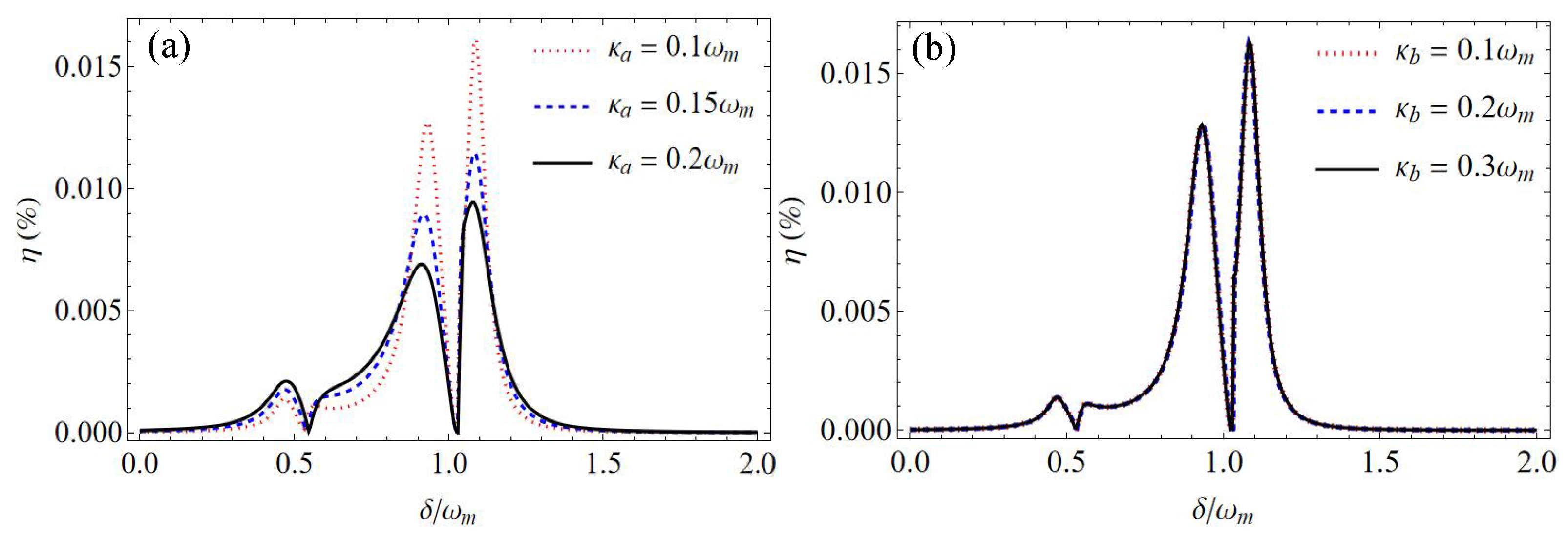
The effects of decay rates and on the efficiency of the second-order upper sideband are shown in Figure 3. Here, the mechanical nonlinearity strength is fixed at N/m2. Figure 3a shows the efficiency as a function of the normalized detuning with different decay rates of cavity a. It is found that the dip of efficiency is almost unchanged with the variations of . The values of two asymmetric sideband peaks decreases with the increasing decay rate of cavity a. For example, the maximum values of efficiency is 0.016% with , which is about 1.8-fold higher than that with . Therefore, the efficiency of the second-order upper sideband can be increased by reducing the decay rate of cavity a. Specifically, the maximum efficiency can be improved to 0.16% with , which is about 10 times that with , and 17.7 times that with . In contrast, the variations in the decay rate of cavity b do not affect the efficiency of the second-order upper sideband , as shown in Figure 3b.
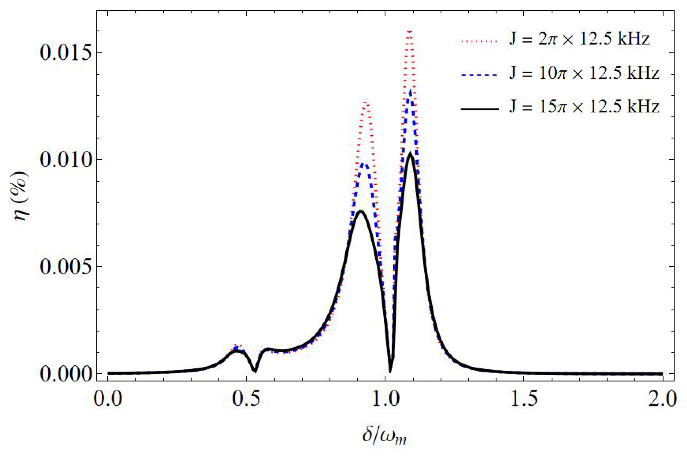
The effect of the coupling strength J on the efficiency of the second-order upper sideband is also discussed. The efficiency as a function of the normalized detuning with different coupling strengths J is shown in Figure 4. Here, the mechanical nonlinearity strength is N/m2, and the decay rates of cavity a and cavity b are . It can be observed from Figure 4 that the dip of efficiency is not affected by the variations in the coupling strength J. The maximum value of efficiency decreases with the increase in the coupling strength J. For example, the maximum efficiency of the second-order upper sideband is 0.016% with the coupling strength kHz, while it is decreased to 0.01% with kHz.
It should be noted that the mechanical nonlinearity strength , the cavity decay rates and , and the coupling strength J are difficult to tune for a fabricated optomechanical system. However, the optomechanical response of the proposed optomechanical system can be adjusted with the power of the control field and probe field. Figure 5a shows the efficiency of the second-order upper sideband as a function of the normalized detuning with the power of the probe field . Here, the mechanical nonlinearity strength is N/m2, cavity decay rates are , the coupling strength is kHz, and the power of the control field is fixed at W. It is found that the maximum efficiency increases with the increase in the power of the probe field . Specifically, the maximum value of is 0.02% with W, while it is improved to 0.035% with the power of the probe field W. Therefore, the efficiency of the second-order upper sideband can be effectively improved by increasing the power of the probe field. For example, the maximum efficiency of 0.203% is achieved with the power of the probe field W, which is about 10.2 times higher than that with W. The effect of the power of the control field on the efficiency of the second-order upper sideband with a fixed power of the probe field is shown in Figure 5b. It is found that the positions of the efficiency peaks are changed with the variations of . In addition, compared to the adjustment of the power of the control field , the variation in the power of the probe field has less of an impact on the maximum efficiency of the second-order upper sideband.
The group delays in the proposed coupled optomechanical cavity system with a cubic nonlinear harmonic oscillator were also investigated. The group delay of the transmitted light in a conventional optomechanical system is only related to the power of the control field [20]. Therefore, the effect of the power of control field on the group delay is considered in this work. The group delay as a function of the coupling field power at the resonance with different cavity decay rates is shown in Figure 6. It was found that only the positive group delay () is observed, which indicates that the slow light effect is achieved with the proposed optomechanical system. For example, the maximum group delay of about 1250 s is obtained with the power of the control field W when the decay rate of cavity a is . In addition, the peak position and peak value of the group delay decreases with the cavity decay rate . Specifically, the maximum group delay decreases from 780 s to 472 s when the decay rate is changed from to , and accordingly, the corresponding power of the control field is changed from W to W. It is worth noting that the positive group delay can also be significantly enhanced with the introduction of cavity b in the coupled optomechanical cavity system. For example, the maximum positive group delay is about 0.007 s with in the coupled optomechanical cavity system without cavity b, which is much smaller than that obtained with both cavity a and cavity b (i.e., 1250 s).
The introduced strong cubic mechanical nonlinearity in the proposed optomechanical system can be obtained with the method proposed in ref. [44]. By coupling the resonators with a low-dimensional auxiliary system, the cubic and even quartic nonlinearity of the mechanical oscillator can be obtained. To obtain a nonlinear harmonic oscillator, a linear mechanical oscillator is coupled to a three-level (qutrit) auxiliary via the interaction . is the interaction strength, and V is an operator of the qutrit. x is the dimensionless position of the mechanical oscillator, which has the relationship of with the displacement operator q. This qutrit has a diagonal auxiliary Hamiltonian that is evenly separated by , and its energy levels are . By placing the auxiliary qutrit in the eigenstate with the energy level and choosing an appropriate operator V, a cubic potential term in the form of can be achieved with the mechanical oscillator. If the interaction strength is MHz, and is GHz, the mechanical nonlinearity strength of can be obtained [6], which is quite close to the value of used in this work. Such an approach to obtaining a cubic nonlinear harmonic oscillator was also adopted in Refs. [6,50].
4. Conclusions
In summary, the generation of second-order sidebands and group delays in a coupled optomechanical cavity system with a cubic nonlinear harmonic oscillator is investigated. The influence of the mechanical nonlinearity strength, the cavity decay rate, the coupling strength between two cavities, the power of the control field, and the power of the probe field on the efficiency of the second-order upper sideband are studied. It is found that the efficiency can be effectively enhanced by reducing the decay rate of cavity a, increasing the coupling strength J and the power of the probe field . The enhanced generation efficiency of second-order sidebands is helpful in frequency conversion for all-optical network communication. In addition, the slow light effect can be achieved with the proposed optomechanical system. The maximum value of the group delay can be effectively controlled by the power of the control field and the decay rate of cavity a.
Author Contributions
Conceptualization, Q.Z. and Y.X.; methodology, Q.Z. and Y.X.; investigation, Q.Z., Y.H. and Y.X.; writing—original draft preparation, Q.Z.; writing—review and editing, Q.Z., Y.H., Y.Y., H.Z. and Y.X.; supervision, Y.H.; project administration, Y.H. All authors have read and agreed to the published version of the manuscript.
Funding
This research was funded by the National Natural Science Foundation of China (Grant No. 12174243).
Institutional Review Board Statement
Not applicable.
Informed Consent Statement
Not applicable.
Data Availability Statement
Data underlying the results presented in this paper are not publicly available at this time, but may be obtained from the authors upon reasonable request.
Conflicts of Interest
The authors declare no conflicts of interest.
References
- Aspelmeyer, M.; Kippenberg, T.J.; Marquardt, F. Cavity optomechanics. Rev. Mod. Phys. 2014, 86, 1391. [Google Scholar] [CrossRef]
- Stannigel, K.; Rabl, P.; Sørensen, A.S.; Zoller, P.; Lukin, M.D. Opto-mechanical transducers for long-distance quantum communication. Phys. Rev. Lett. 2010, 105, 220501. [Google Scholar] [CrossRef]
- Gavartin, E.; Verlot, P.; Kippenberg, T.J. A hybrid on-chip optonanomechanical transducer for ultra-sensitive force measurements. Nat. Nanotechnol. 2012, 7, 509–514. [Google Scholar] [CrossRef]
- Clark, J.B.; Lecocq, F.; Simmonds, R.W.; Aumentado, J.; Teufel, J.D. Sideband cooling beyond the quantum backaction limit with squeezed light. Nature 2017, 541, 191–195. [Google Scholar] [CrossRef]
- Qiu, L.; Shomroni, I.; Seidler, P.; Kippenberg, T.J. Laser cooling of a nanomechanical oscillator to its zero-point energy. Phys. Rev. Lett. 2020, 124, 173601. [Google Scholar] [CrossRef]
- Huang, S.; Hao, H.; Chen, A. The optomechanical response of a cubic anharmonic oscillator. Appl. Sci. 2020, 10, 5719. [Google Scholar] [CrossRef]
- Lemonde, M.A.; Didier, N.; Clerk, A.A. Nonlinear interaction effects in a strongly driven optomechanical cavity. Phys. Rev. Lett. 2013, 111, 053602. [Google Scholar] [PubMed]
- Børkje, K.; Nunnenkamp, A.; Teufel, J.D.; Girvin, S.M. Signatures of nonlinear cavity optomechanics in the weak coupling regime. Phys. Rev. Lett. 2013, 111, 053603. [Google Scholar] [CrossRef] [PubMed]
- Riedinger, R.; Hong, S.; Norte, R.A.; Slater, J.A.; Shang, J.; Krause, A.G.; Anant, V.; Aspelmeyer, M.; Groblacher, S. Non-classical correlations between single photons and phonons from a mechanical oscillator. Nature 2016, 530, 313–316. [Google Scholar] [CrossRef] [PubMed]
- Paternostro, M.; Vitali, D.; Gigan, S.; Kim, M.S.; Brukner, C.; Eisert, J.; Aspelmeyer, M. Creating and probing multipartite macroscopic entanglement with light. Phys. Rev. Lett. 2007, 99, 250401. [Google Scholar] [CrossRef] [PubMed]
- Palomaki, T.A.; Teufel, J.D.; Simmonds, R.W.; Lehnert, K.W. Entangling mechanical motion with microwave fields. Science 2013, 342, 710–713. [Google Scholar] [CrossRef] [PubMed]
- Grblacher, S.; Hammerer, K.; Vanner, M.R.; Aspelmeyer, M. Observation of strong coupling between a micromechanical resonator and an optical cavity field. Nature 2009, 460, 724–727. [Google Scholar] [CrossRef]
- Dobrindt, J.M.; Wilson-Rae, I.; Kippenberg, T.J. Parametric Normal-mode splitting in cavity optomechanics. Phys. Rev. Lett. 2008, 101, 263602. [Google Scholar] [CrossRef] [PubMed]
- Rossi, M.; Kralj, N.; Zippilli, S.; Natali, R.; Borrielli, A.; Pandraud, G.; Serra, E.; Di Giuseppe, G.; Vitali, D. Normal-mode splitting in a weakly coupled optomechanical system. Phys. Rev. Lett. 2018, 120, 073601. [Google Scholar] [CrossRef]
- Jaehne, K.; Genes, C.; Hammerer, K.; Wallquist, M.; Polzik, E.S.; Zoller, P. Cavity-assisted squeezing of a mechanical oscillator. Phys. Rev. A 2009, 79, 063819. [Google Scholar] [CrossRef]
- Agarwal, G.S.; Huang, S. Strong mechanical squeezing and its detection. Phys. Rev. A 2016, 93, 043844. [Google Scholar] [CrossRef]
- Wollman, E.E.; Lei, C.U.; Weinstein, A.J.; Suh, J.; Kronwald, A.; Marquardt, F.; Clerk, A.A.; Schwab, K.C. Quantum squeezing of motion in a mechanical resonator. Science 2015, 349, 952–955. [Google Scholar] [CrossRef]
- Agarwal, G.S.; Huang, S. Electromagnetically induced transparency in mechanical effects of light. Phys. Rev. A 2010, 81, 041803. [Google Scholar] [CrossRef]
- Weis, S.; Riviere, R.; Deleglise, S.; Gavartin, E.; Arcizet, O.; Schliesser, A.; Kippenberg, T.J. Optomechanically induced transparency. Science 2010, 330, 1520–1523. [Google Scholar] [CrossRef]
- Safavi-Naeini, A.H.; Alegre, T.M.; Chan, J.; Eichenfield, M.; Winger, M.; Lin, Q.; Hill, J.T.; Chang, D.E.; Painter, O. Electromagnetically induced transparency and slow light with optomechanics. Nature 2011, 472, 69–73. [Google Scholar] [CrossRef]
- Dong, C.; Fiore, V.; Kuzyk, M.C.; Wang, H. Transient optomechanically induced transparency in a silica microsphere. Phys. Rev. A 2013, 87, 055802. [Google Scholar] [CrossRef]
- Jain, M.; Xia, H.; Yin, G.Y.; Merriam, A.J.; Harris, S.E. Efficient nonlinear frequency conversion with maximal atomic coherence. Phys. Rev. Lett. 1996, 77, 4326. [Google Scholar] [CrossRef] [PubMed]
- Zhou, X.; Hocke, F.; Schliesser, A.; Marx, A.; Huebl, H.; Gross, R.; Kippenberg, T.J. Slowing, advancing and switching of microwave signals using circuit nanoelectromechanics. Nat. Phys. 2013, 9, 179–184. [Google Scholar] [CrossRef]
- Lvovsky, A.I.; Sanders, B.C.; Tittel, W. Optical quantum memory. Nat. Photonics 2009, 3, 706–714. [Google Scholar] [CrossRef]
- Agarwal, G.S.; Huang, S. Optomechanical systems as single photon routers. Phys. Rev. A 2012, 85, 021801(R). [Google Scholar] [CrossRef]
- Karuza, M.; Biancofiore, C.; Bawaj, M.; Molinelli, C.; Galassi, M.; Natali, R.; Tombesi, P.; Di Giuseppe, G.; Vitali, D. Optomechanically induced transparency in a membrane-in-the-middle setup at room temperature. Phys. Rev. A 2013, 88, 013804. [Google Scholar] [CrossRef]
- Xiong, H.; Wu, Y. Fundamentals and applications of optomechanically induced transparency. Appl. Phys. Rev. 2018, 5, 031305. [Google Scholar] [CrossRef]
- Chen, B.; Jiang, C.; Zhu, K.D. Slow light in a cavity optomechanical system with a Bose–Einstein condensate. Phys. Rev. A 2011, 83, 055803. [Google Scholar] [CrossRef]
- Akram, M.J.; Khan, M.M.; Saif, F. Tunable fast and slow light in a hybrid optomechanical system. Phys. Rev. A 2015, 92, 023846. [Google Scholar] [CrossRef]
- Lü, H.; Wang, C.; Yang, L.; Jing, H. Optomechanically induced transparency at exceptional points. Phys. Rev. Appl. 2018, 10, 014006. [Google Scholar] [CrossRef]
- Jiang, C.; Cui, Y.; Zhai, Z.; Yu, H.; Li, X.; Chen, G. Phase-controlled amplification and slow light in a hybrid optomechanical system. Opt. Express 2019, 27, 30473–30485. [Google Scholar] [CrossRef]
- Xu, Y.; Liu, W. Fano resonance and slow-to-fast light conversion in a Laguerre–Gaussian rovibrational cavity. J. Lightwave Technol. 2022, 41, 2246–2251. [Google Scholar] [CrossRef]
- Xiong, H.; Si, L.G.; Zheng, A.S.; Yang, X.X.; Wu, Y. Higher-order sidebands in optomechanically induced transparency. Phys. Rev. A 2012, 86, 013815. [Google Scholar] [CrossRef]
- Kronwald, A.; Marquardt, F. Optomechanically induced transparency in the nonlinear quantum regime. Phys. Rev. Lett. 2013, 111, 133601. [Google Scholar] [CrossRef] [PubMed]
- Jiao, Y.F.; Lu, T.X.; Jing, H. Optomechanical second-order sidebands and group delays in a Kerr resonator. Phys. Rev. A 2018, 97, 013843. [Google Scholar] [CrossRef]
- Wang, B.; Liu, Z.X.; Xiong, H.; Wu, Y. Highly sensitive mass sensing by means of the optomechanical nonlinearity. IEEE Photonics J. 2018, 10, 6803908. [Google Scholar] [CrossRef]
- Kong, C.; Xiong, H.; Wu, Y. Coulomb-interaction-dependent effect of high-order sideband generation in an optomechanical system. Phys. Rev. A 2017, 95, 033820. [Google Scholar] [CrossRef]
- Xiong, H.; Si, L.G.; Wu, Y. Precision measurement of electrical charges in an optomechanical system beyond linearized dynamics. Appl. Phys. Lett. 2017, 110, 171102. [Google Scholar] [CrossRef]
- Chen, B.; Shang, L.; Wang, X.F.; Chen, J.B.; Xue, H.B.; Liu, X.; Zhang, J. Atom-assisted second-order sideband generation in an optomechanical system with atom-cavity-resonator coupling. Phys. Rev. A 2019, 99, 063810. [Google Scholar] [CrossRef]
- Catalini, L.; Rossi, M.; Langman, E.C.; Schliesser, A. Modeling and observation of nonlinear damping in dissipation-diluted nanomechanical resonators. Phys. Rev. Lett. 2021, 126, 174101. [Google Scholar] [CrossRef]
- Lü, X.Y.; Liao, J.Q.; Tian, L.; Nori, F. Steady-state mechanical squeezing in an optomechanical system via Duffing nonlinearity. Phys. Rev. A 2015, 91, 013834. [Google Scholar] [CrossRef]
- Huang, P.; Zhou, J.; Zhang, L.; Hou, D.; Lin, S.; Deng, W.; Meng, C.; Duan, C.; Ju, C.; Zheng, X.; et al. Generating giant and tunable nonlinearity in a macroscopic mechanical resonator from a single chemical bond. Nat. Commun. 2016, 7, 11517. [Google Scholar] [CrossRef]
- Kaajakari, V.; Mattila, T.; Oja, A.; Seppa, H. Nonlinear limits for single-crystal silicon microresonators. J. Microelectromech. Syst. 2004, 13, 715–724. [Google Scholar] [CrossRef]
- Jacobs, K.; Landahl, A.J. Engineering giant nonlinearities in quantum nanosystems. Phys. Rev. Lett. 2009, 103, 067201. [Google Scholar] [CrossRef] [PubMed]
- Grimm, M.; Bruder, C.; Lörch, N. Optomechanical self-oscillations in an anharmonic potential: Engineering a nonclassical steady state. J. Opt. 2016, 18, 094004. [Google Scholar] [CrossRef]
- Djorwé, P.; Engo, S.N.; Woafo, P. Robustness of continuous-variable entanglement via geometrical nonlinearity. Phys. Rev. A 2014, 90, 024303. [Google Scholar] [CrossRef]
- Hao, H.; Huang, S.; Chen, A. Normal mode splitting in a cavity optomechanical system with a cubic anharmonic oscillator. Int. J. Theor. Phys. 2021, 60, 2766–2777. [Google Scholar] [CrossRef]
- Lv, W.; Deng, L.; Huang, S.; Chen, A. Optomechanically induced transparency in optomechanical system with a cubic anharmonic oscillator. Photonics 2023, 10, 407. [Google Scholar] [CrossRef]
- Saiko, A.P.; Fedaruk, R.; Markevich, S. Kerr-like nonlinearities in an optomechanical system with an asymmetric anharmonic mechanical resonator. JETP Lett. 2021, 113, 487–492. [Google Scholar] [CrossRef]
- Huang, S.; Wu, Y.; Chen, A. The stationary optomechanical entanglement between an optical cavity field and a cubic anharmonic oscillator. Int. J. Theor. Phys. 2021, 60, 3961–3972. [Google Scholar] [CrossRef]
- Latmiral, L.; Armata, F.; Genoni, M.G.; Pikovski, I.; Kim, M. Probing anharmonicity of a quantum oscillator in an optomechanical cavity. Phys. Rev. A 2016, 93, 052306. [Google Scholar] [CrossRef]
- Yaris, R.; Bendler, J.; Lovett, R.A.; Bender, C.M.; Fedders, P.A. Resonance calculations for arbitrary potentials. Phys. Rev. A 1978, 18, 1816. [Google Scholar] [CrossRef]
- Alvarez, G. Coupling-constant behavior of the resonances of the cubic anharmonic oscillator. Phys. Rev. A 1988, 37, 4079. [Google Scholar] [CrossRef] [PubMed]
- Cveticanin, L.; Zukovic, M.; Mester, G.; Biro, I.; Sarosi, J. Oscillators with symmetric and asymmetric quadratic nonlinearity. Acta Mech. 2016, 227, 1727–1742. [Google Scholar] [CrossRef]
- Bender, C.M.; Dunne, G.V. Large-order perturbation theory for a non-Hermitian PT-symmetric Hamiltonian. J. Math. Phys. 1998, 40, 4616–4621. [Google Scholar] [CrossRef]
- Bender, C.M.; Weniger, E.J. Numerical evidence that the perturbation expansion for a non-Hermitian PT-symmetric Hamiltonian is Stieltjes. J. Math. Phys. 2001, 42, 2167–2183. [Google Scholar] [CrossRef]
- Mera, H.; Pedersen, T.G.; Nikolić, B.K. Nonperturbative quantum physics from low-order perturbation theory. Phys. Rev. Lett. 2015, 115, 143001. [Google Scholar] [CrossRef]
Figure 1.
Schematic diagram of the proposed coupled optomechanical cavity system with a cubic nonlinear harmonic oscillator.
Figure 1.
Schematic diagram of the proposed coupled optomechanical cavity system with a cubic nonlinear harmonic oscillator.
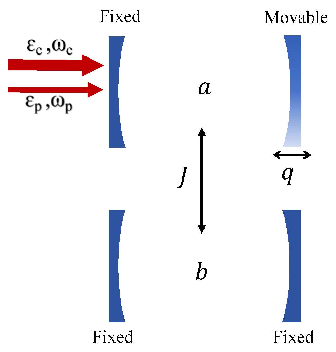
Figure 2.
The efficiency as a function of the normalized detuning with a different mechanical nonlinearity strength .
Figure 2.
The efficiency as a function of the normalized detuning with a different mechanical nonlinearity strength .
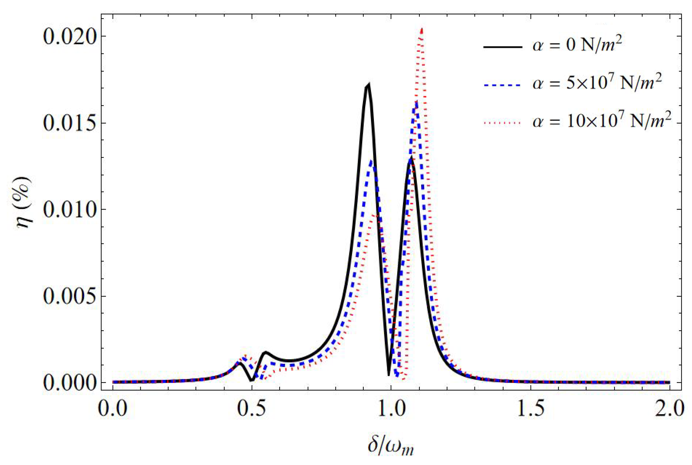
Figure 3.
The efficiency as a function of the normalized detuning with different cavity decay rates (a) : (red dotted line), (blue dashed line), and (black solid line) for , and (b) : (red dotted line), (blue dashed line), and (black solid line) for . Here, the mechanical nonlinearity strength is N/m2.

Figure 4.
The efficiency as a function of the normalized detuning with different coupling strengths J. Here, N/m2, and .
Figure 4.
The efficiency as a function of the normalized detuning with different coupling strengths J. Here, N/m2, and .

Figure 5.
The efficiency as a function of the normalized detuning with a different (a) power of the probe field and (b) power of the control field . The power of the control field is W in (a), and the power of the probe field is W in (b). Here, the mechanical nonlinearity strength is N/m2, cavity decay rates are , and the coupling strength is J = kHz.
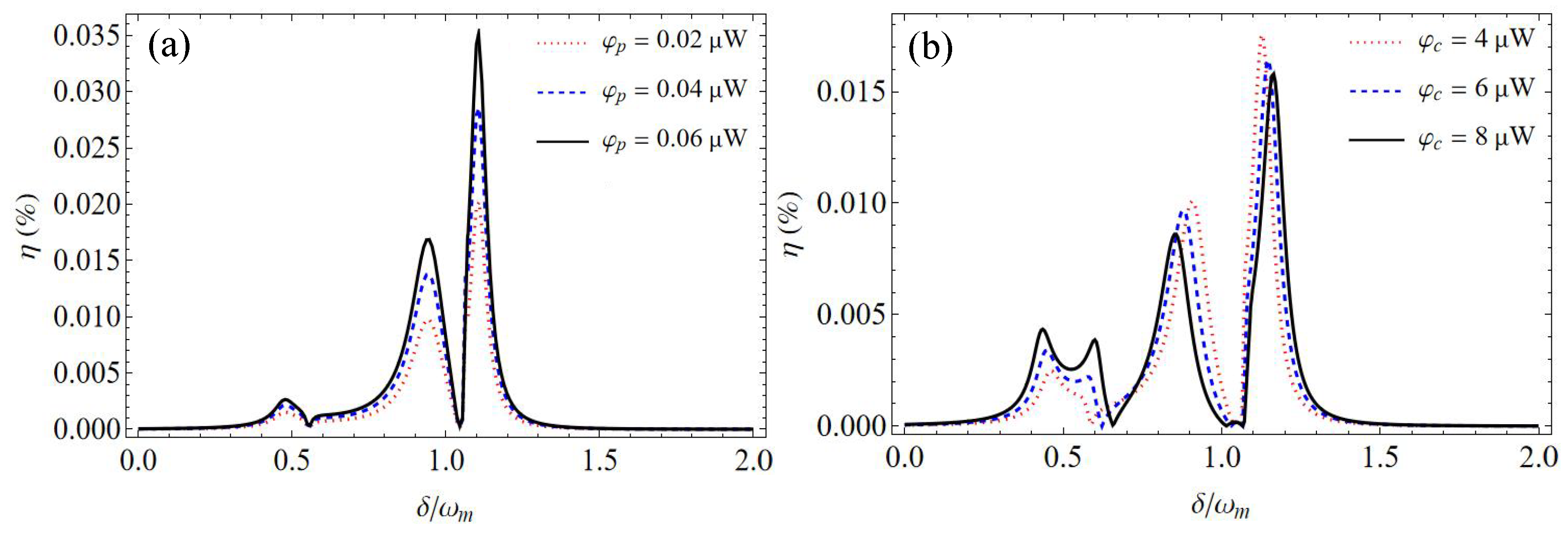
Figure 6.
Group delay as a function of the coupling field power at the resonance with different cavity decay rates for the proposed coupled optomechanical cavity system with (a) both the cavity a and cavity b, and (b) only cavity a. Here, , and the mechanical nonlinearity strength is N/m2.
Figure 6.
Group delay as a function of the coupling field power at the resonance with different cavity decay rates for the proposed coupled optomechanical cavity system with (a) both the cavity a and cavity b, and (b) only cavity a. Here, , and the mechanical nonlinearity strength is N/m2.

Disclaimer/Publisher’s Note: The statements, opinions and data contained in all publications are solely those of the individual author(s) and contributor(s) and not of MDPI and/or the editor(s). MDPI and/or the editor(s) disclaim responsibility for any injury to people or property resulting from any ideas, methods, instructions or products referred to in the content. |
© 2024 by the authors. Licensee MDPI, Basel, Switzerland. This article is an open access article distributed under the terms and conditions of the Creative Commons Attribution (CC BY) license (https://creativecommons.org/licenses/by/4.0/).
Share and Cite
MDPI and ACS Style
Zhao, Q.; He, Y.; Yang, Y.; Zhang, H.; Xu, Y. Second-Order Sidebands and Group Delays in Coupled Optomechanical Cavity System with a Cubic Nonlinear Harmonic Oscillator. Photonics 2024, 11, 256. https://doi.org/10.3390/photonics11030256
AMA Style
Zhao Q, He Y, Yang Y, Zhang H, Xu Y. Second-Order Sidebands and Group Delays in Coupled Optomechanical Cavity System with a Cubic Nonlinear Harmonic Oscillator. Photonics. 2024; 11(3):256. https://doi.org/10.3390/photonics11030256
Chicago/Turabian StyleZhao, Qiwen, Ying He, Yanfang Yang, Huifang Zhang, and Yi Xu. 2024. "Second-Order Sidebands and Group Delays in Coupled Optomechanical Cavity System with a Cubic Nonlinear Harmonic Oscillator" Photonics 11, no. 3: 256. https://doi.org/10.3390/photonics11030256
Note that from the first issue of 2016, this journal uses article numbers instead of page numbers. See further details here.