Multi-Mode Long-Wavelength GaAs/AlGaAs Quantum Well Infrared Photodetectors for Circular Polarization Detection

1
Key Laboratory of Polarized Materials and Devices (MOE), Department of Electronics, East China Normal University, Shanghai 200241, China
2
Shanghai Key Laboratory of Multidimensional Information Processing, East China Normal University, Shanghai 200241, China
*
Author to whom correspondence should be addressed.
Photonics 2024, 11(4), 285; https://doi.org/10.3390/photonics11040285
Submission received: 28 February 2024
/
Revised: 18 March 2024
/
Accepted: 19 March 2024
/
Published: 22 March 2024
(This article belongs to the Special Issue Advanced Photonic Sensing and Measurement II)
Abstract
:We present an integrated device combining a double L-shaped chiral metasurface with long-wavelength GaAs/AlGaAs quantum well infrared photodetectors (QWIPs), achieving a circular polarized extinction ratio (CPER) as high as 45 in the long-wavelength infrared range of 7–9 μm. The unit of the chiral metasurface array consists of two structurally identical L-shaped gold structures with central symmetry. The CPER of the double L-shaped QWIPs is 14 times higher than that of a single L-shaped QWIP. The device operates in three modes within the detection band: the microcavity mode, the surface plasmon polariton (SPP) mode, and the hybrid mode. The double L-shaped chiral structure selects and reflects a small portion of left-handed circularly polarized light (LCP), while the majority enters the device and excites SPP modes with the bottom gold grating layer, leading to an absorption enhancement. In contrast, right-handed circularly polarized light (RCP) is mostly reflected with limited excitation of SPP waves. QWIPs exhibit a peak absorption of 0.8 and a coupling efficiency of 2700% in the active region of the quantum well due to the combined effects of the microcavity and SPP modes, in which the SPP mode plays a dominant role. The proposed device maintains high circular polarization discrimination capability under large incident angles and can be applied in spectral imaging.
1. Introduction
Polarization detection can enable the accurate identification of targets in complex backgrounds by obtaining their unique polarization signatures and has been applied in various fields [1,2,3]. To determine the polarization direction of light, circular dichroism (CD) is utilized, which refers to the difference in absorption between the two spin states of circularly polarized light (CPL). However, traditional infrared polarization devices require complex optical systems designed in front of focal plane arrays to obtain polarization information. These devices suffer from drawbacks such as complex manufacturing processes, high costs, redundancy in components, and large volume [4,5]. Quantum well infrared photodetectors (QWIPs) are low-cost infrared detectors known for their fast response, high sensitivity, tunable detection wavelengths, and ease of manufacturing focal plane arrays [6]. However, QWIPs operate based on subband transitions; thus, they are incapable of absorbing infrared light incident perpendicular to their surface, leading to lower quantum efficiency and hindering their development [7].
With increasing demands for polarization detection devices combining miniaturization and high performance, the integration of chiral metasurfaces with QWIPs offers a promising solution [8,9]. By designing structures of integrated chiral metasurface, QWIPs can distinguish between left-handed circularly polarized light (LCP) and right-handed circularly polarized light (RCP) based on different absorption rates and coupling efficiencies, exhibiting excellent circular polarization discrimination capabilities [10,11,12].
In this paper, we present a double L-shaped chiral metasurface-enhanced long-wavelength GaAs/AlGaAs QWIP that achieves a high circular polarization extinction ratio (CPER) up to 45 in the long-wavelength infrared range of 7–9 μm. Here, CPER represents the ratio of coupling efficiency [13] under LCP light to that under RCP light. The chiral structure employs a special double L design that exhibits a CPER 14 times higher than that of a single L structure. Within the detection wavelength range, the device operates in three modes: the microcavity mode, the surface plasmon polariton (SPP) mode, and the hybrid mode. The device achieves a peak absorption of 0.8 and a coupling efficiency of 2700% in the quantum well active region at 7.9 μm due to the combined effects of the microcavity and SPP modes, where the SPP mode plays a dominant role. The double L-shaped structure enhances the circular polarization discrimination capability of QWIPs and can maintain high performance, even in large incident angles.
2. Materials and Methods
Figure 1a–c sequentially illustrates the front view with an energy band diagram, a three-dimensional view, and a top view of the long-wavelength GaAs/AlGaAs QWIPs. The quantum well region consists of 10 periods of Al0.27Ga0.73As/GaAs single quantum wells. This material was employed in the research conducted by Jeong in 2005 [14], with the experimental devices operating in the wavelength region around 8 μm. The author has verified that reliable etching depth can be achieved for this material using wet etching methods in experiment. In our QWIPs, the quantum well has a width of 4.8 nm and a barrier width of 50 nm. The energy difference between the ground state energy level E1 and the first excited state energy level E2 for the inter-subband transition is 153 meV. The active region thickness is h3 = 0.6 μm, and the thickness of the bottom and top contact layers is h1 = h4 = 1.1 μm. The contact layer is composed of GaAs doped with Si at a concentration of 1 × 1018 cm−3. The gold stripe grating has a width of s = 0.5 μm and a thickness of h2 = 0.2 μm. The unit cell of the chiral metasurface array is composed of two structurally identical L-shaped gold structures with central symmetry. The unit cell period is Px = Py = 2.5 μm. The double L-shaped structure has a thickness of h5 = 0.2 μm, a width of a = 0.4 μm, a short side length of b = 1 μm, a long side length of c = 1.8 μm, and a separation distance of d = 0.8 μm.
The fabrication of the proposed chiral metasurface-enhanced QWIPs has been demonstrated to be feasible in previous works, where they are hybridized with a fanout circuit through standard flip-chip bonding processes [15]. Initially, dielectric layers are grown on GaAs wafers by molecular beam epitaxy (MBE). Subsequently, wet etching is employed to obtain photosensitive mesas, controlling the mesa depth to reach the top contact layer. Inductive coupled plasma etching is used to etch the bottom contact layer. Then, Au is deposited via electron-beam evaporation to form gold stripe grating and a metal reflection layer. Finally, the double L-shaped metal array can be formed through electron-beam evaporation and lift-off processes.
In this study, the Finite-Difference Time-Domain (FDTD) method was used for calculations. The relative permittivity of gold was obtained by the Drude model [16]:
In the equation, ω represents the frequency of the incident wave, ωp = 1.37 × 10¹⁶ rad/s is the plasma frequency, and ωτ = 4.65 × 10¹³ rad/s is the damping constant of gold.
The quantum well active region is an anisotropic material, and its dielectric constant can be represented as diag(εx, εy, εz), where εx and εy follow the material model of GaAs, as shown in the following equation [17]:
In this equation, ε∞ = 11 represents the high-frequency dielectric constant, fL = 8.757 THz represents the longitudinal optical phonon frequency, and fT = 8.056 THz represents the transverse optical phonon frequency. γT = 72 GHz is the phonon damping constant.
In the z-direction, the equation is given as follows:
where fw represents the peak frequency of the response, while γw = 0.05fw corresponds to the damping factor [18]. ε′ denotes the real part of the complex permittivity at the peak wavelength, which is typically assigned a value of 0.5 [19].
The coupling efficiency (CE) of the active region in the quantum wells structure can be calculated using the following equation [13]:
The equation includes E0 as the initial electric field and Ez as the electric field component in the z-direction. In this study, CPER represents the ratio of coupling efficiency between LCP light and RCP light. A higher value of CPER indicates better circular polarization detection performance of the detector.
3. Results and Discussion
Figure 2 shows the real and imaginary parts of the relative permittivity in the z-direction for the active region of the designed quantum well structure. Figure 3a depicts the absorption spectrum of the long-wavelength GaAs/AlGaAs QWIPs, where the black line represents the LCP light source and the red line represents the RCP light source. Three peaks are observed at wavelengths of 7.5 μm, 7.9 μm, and 8.0 μm, corresponding to the microcavity mode [20,21], the SPP mode [22,23], and a hybrid mode [24] of the two. In the SPP mode at 7.9 μm, the maximum absorption for LCP light source is 0.8, while the absorption for RCP light source is only 0.25. Across all three operating modes, the device exhibits significantly higher absorption for LCP light sources compared to RCP light sources. Figure 3b displays the coupling efficiency of the active region of the quantum well as a function of wavelength. When the LCP light source is incident, the coupling efficiency reaches 2700% at 7.9 μm and 870% at 8.0 μm. On the other hand, when the RCP light source is incident, the coupling efficiency at 7.9 μm and 8.0 μm is 60% and 540%, respectively. Figure 3c represents the CPER of this QWIP device with a maximum value of 45 at 7.9 μm.
Figure 3d–f show the |Ez|/|E0| (where Ez represents the electric field component in the z-direction and E0 represents the initial electric field) under LCP light illumination for the three operating modes. This is the xoz cross-section at y = 0, and the z-axis coordinates are zero on the upper surface of the bottom gold base. When the incident light passes through the top chiral metasurface layer, the microcavity mode is excited. Selected by the chiral structure, most of the RCP light is reflected, while a significant amount of LCP light transmits into the QWIPs and excites the SPP mode in the bottom gold stripe grating layer, where it is subsequently absorbed. The electric field enhancement of the microcavity mode is mainly concentrated at the top of the device, while the SPP mode exhibits enhanced electric fields over the entire semiconductor layer. Although the hybrid mode is a combination of the two, the excited electric field is weaker and primarily concentrated on the metal surface. Among the three operating modes, the dominant mode is the SPP mode. Under the SPP mode, the maximum enhancement of |Ez|/|E0| is 8.7 times with a higher amplitude and a broader range compared to the other modes, which is consistent with the higher absorption rate observed in Figure 3a for the SPP mode.
Figure 3g–i show the |EZ/E0| in xoz cross-section (y = 0) under three operating modes when RCP light is incident, setting the upper surface of the bottom gold base as the coordinate zero plane. In the microcavity mode at 7.5 μm, although the electric field enhancement amplitude of RCP light is smaller than that of LCP light, its radiation range is wider, resulting in higher overall absorption of the QWIPs, consistent with the results in Figure 3a. After passing through the top double L-shaped chiral structure, circularly polarized light of different handedness experiences different phase shifts. LCP light effectively excites SPP waves, enhancing the localized electric field, while SPP waves excited by RCP light are suppressed. At 7.9 μm and 8.1 μm, the electric field enhancement of RCP light is smaller than that of LCP light. With the combined effects of the top chiral metasurface and the bottom gold grating, the QWIPs can absorb most of the LCP light and a small amount of RCP light. The significant difference between the two results in a remarkable CPER of up to 45, demonstrating the device’s capability to effectively discriminate the handedness of circularly polarized light.
Due to the dominant role of SPP waves excited by the bottom gold stripe grating in the three operating modes, this study investigates the influence of the grating width (s) and thickness (h2) on the device performance. As shown in Figure 4a,b, we examine the relationship between the coupling efficiency (CE) and the response wavelength for different grating widths (s). When RCP light is incident, the CE initially decreases and then increases at the SPP wave response wavelength of 7.9 μm as s varies from 0.3 μm to 0.5 μm, reaching a local minimum at s = 0.5 μm. When LCP light is incident, the CE reaches a local maximum at s = 0.5 μm. It can be observed that at s = 0.5 μm, the SPP effect is suppressed under RCP light and enhanced under LCP light, resulting in a significant difference in CE between the two polarizations. Therefore, the QWIPs exhibits the ability to distinguish the rotational direction of circularly polarized light. Due to the unchanged parameters of the top double L-shaped chiral structures, the response wavelength and intensity of the microcavity effect excited at 8.1 μm tend to stabilize, regardless of whether it is RCP light or LCP light. From Figure 4c, it can be visually observed that the CPER reaches its maximum value at s = 0.5 μm. It should be noted that when s is between 0.3 μm and 0.4 μm, the CPER value between 7.6 μm and 8 μm is less than 1, indicating that under this condition, the CE for RCP light is stronger than that for LCP light.
Figure 5 illustrates the impact of different grating thicknesses (h2) on the QWIPs. As shown in Figure 5a,b, under RCP light incidence, the CE initially decreases and then increases at the SPP wave response wavelength of 7.9 μm as h2 varies from 0.1 μm to 0.3 μm, reaching a local minimum at h2 = 0.2 μm. Under LCP light incidence, CE maintains a relatively high value in the range of h2 = 0.2–0.3 μm. When h2 is less than 0.2 μm, CE rapidly decays, resulting in weaker CE for LCP light compared to RCP light, which is consistent with the results in Figure 5c. The device achieves the maximum CPER when h2 = 0.2 μm. In addition to exciting SPP waves on the surface of the gold grating, the incident light also generates transverse diffracted light and reflected light, leading to interference phenomena [25]. When h2 and s are small, the destructive interference caused by LCP light weakens the SPP effect, while the constructive interference caused by RCP light enhances the SPP effect, resulting in a CPER value less than 1. Changes in the grating structure parameters can affect the excitation of the SPP effect, making the selection of appropriate values for s and h2 crucial for device performance.
In this study, the impact of L-shaped structures on CPER was investigated through a comparison of individual L-shaped structures, L1 and L2, as well as the double L-shaped structure. The coupling efficiency curves for L1 and L2 structures are depicted in Figure 6a,b. Due to their central symmetry, the coupling efficiency curves of L1 and L2 structures exhibit similarities. At a wavelength of 7.9 μm, the coupling efficiency (CE) for LCP light is 2400%, while the CE for RCP light is 1060%. Figure 6c presents a comparison of the CPER between the double L-shaped structure and the single L-shaped structures. The illustration shows the coupling efficiency of the double L-shaped structure. In comparison to the single L-shaped structures, the double L-shaped structure does not exhibit a significant enhancement in the CE for LCP light. However, it significantly suppresses the CE for RCP light. The maximum CPER for the single L-shaped structure is only 3.2, whereas the CPER for the double L-shaped structure is 14 times higher than that of the single L-shaped structures. These findings indicate that double L-shaped long-wavelength GaAs/AlGaAs QWIPs can effectively improve CPER and enhance the circular polarization detection capabilities of the device and be applied in medical in spectral imaging [26].
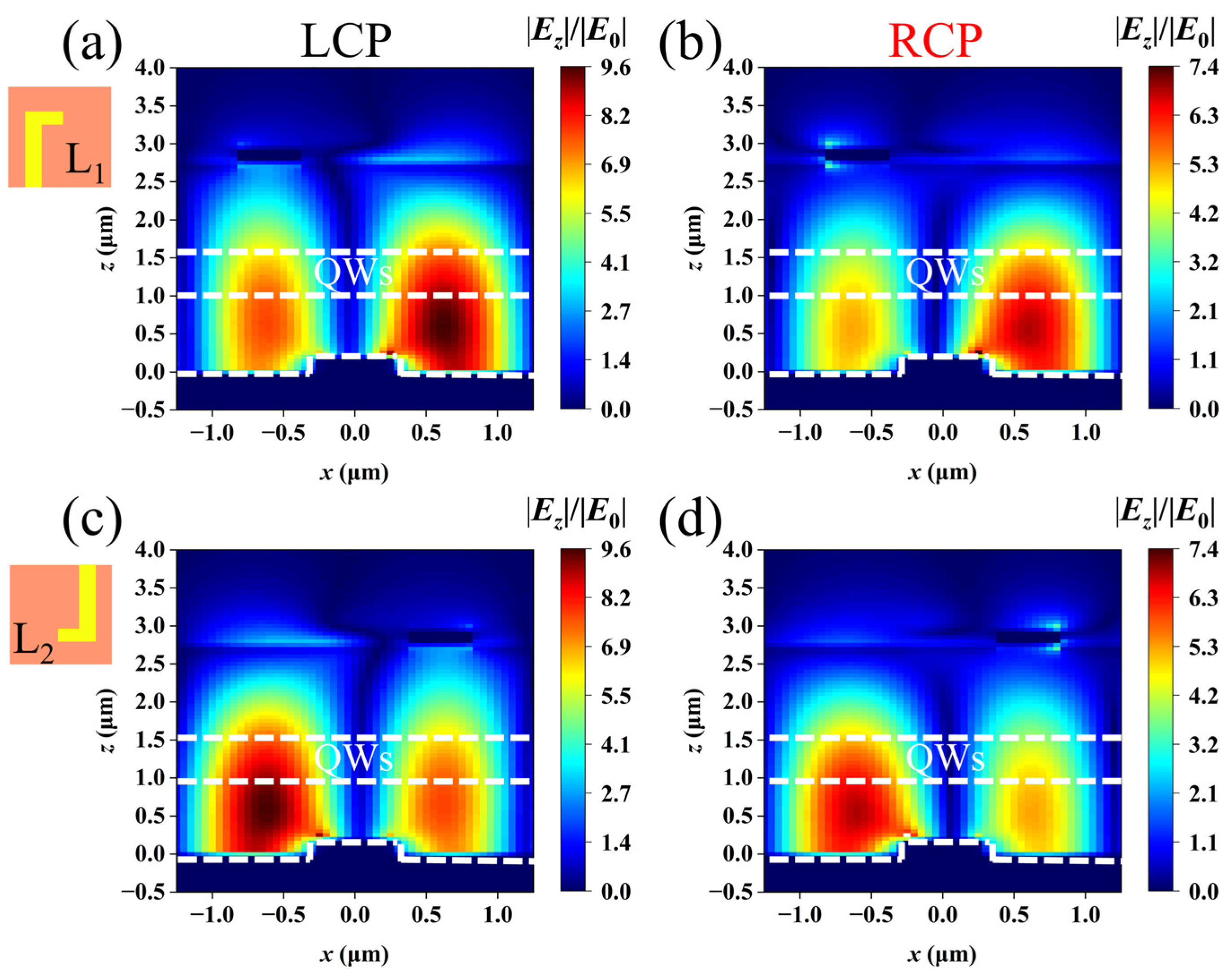
Subsequently, we analyzed the electric field distribution of the single L-shaped structure. Figure 7a and Figure 7b, respectively, present the |Ez|/|E0| of the L1 structure under LCP and RCP light at the peak wavelength of 7.9 μm in xoz plane. The maximum enhancement of |Ez|/|E0| for the LCP incident reaches 9.6 times, surpassing the 8.7 times observed for the double L-shaped structure in Figure 3c. This is attributed to a considerable portion of incident light directly transmitting into the cavity through the uncovered top contact layer by the L-shaped structure, thereby enhancing the local field. However, this portion of incident light is not converted by the top chiral metasurface and the excited SPP effect is limited, resulting in an overall coupling efficiency lower than that of the double L-shaped structure. This also explains why the peak coupling efficiency in Figure 6a,b is lower than 2500%. In Figure 7b, the maximum enhancement of |Ez|/|E0| caused by the SPP waves reaches 7.4 times, which is weaker than that of LCP light. This confirms that the single L-shaped structure also possesses a certain ability to discriminate the rotation direction of circularly polarized light, although with a smaller difference between the LCP and RCP light compared to the double L-shaped structure. This explains why the CPER of the single L-shaped structure is lower than that of the double L-shaped structure in Figure 6c.
The |Ez|/|E0| values of the L2 structure under LCP and RCP light at the peak wavelength of 7.9 μm, as shown in Figure 7c,d, are consistent with the enhancement amplitudes in Figure 7a,b due to the central symmetry between L1 and L2 structure. However, the excitation position of the SPP mode is different: for L1, it is on the right (left) side of the unit, while for L2, it is on the left (right) side of the unit under LCP (RCP) light. This is because, as mentioned earlier, the incident light is transmitted through the top contact layer, not covered by the metal stripes. The mirrored symmetric electric field distribution also explains why the coupling efficiency curves of L1 and L2 in Figure 6a,b are consistent. Therefore, through a comparative study of single L-shaped and double L-shaped structures, we can observe that the performance of the double L-shaped structure is superior than that of the single L-shaped structure in terms of the coupling efficiency and circular polarization discrimination capability.
In order to investigate the circular polarization selectivity of double L-shaped chiral structures, we manipulated the position of the top double L-shaped structure by symmetrically flipping it about the x-axis, thereby modifying the device’s target polarization to RCP light. Figure 8a illustrates the absorption spectrum of the flipped device, with an inset schematic of the right-handed chiral double L-shaped structure targeted towards RCP light. The numerical values of absorption peaks, peak wavelengths, and peak absorption ratios remain consistent with the results in Figure 3a. However, RCP light plays a dominant role rather than LCP light. Figure 8b and Figure 8c, respectively, demonstrate the coupling efficiency curve and the CPER of the right-handed chiral double L-shaped structure. At the peak wavelength of 7.9 μm, the coupling efficiency under RCP light hits 2700%, which is significantly higher than the 60% under LCP light. Similarly, at the wavelength of 8.1 μm, the coupling efficiency of RCP light surpasses that of LCP light. This stands in stark contrast to the results in Figure 3b. The peak CPER in Figure 8c is consistent with that in Figure 3c; however, the CPER here is obtained by calculating the ratio of coupling efficiencies between RCP and LCP light. These results confirm that this design can achieve free selection of detecting the target rotation of circularly polarized light by altering the layout of the double L structure, thereby exhibiting wide applicability.
In the application of QWIPs, it is essential to evaluate the performance of chiral metasurfaces with various incident angles, including coupling efficiency and CPER. Investigating the device performance under different incident angles allows for the assessment of angle independence, thereby providing guidance for the design and optimization in practical applications. Figure 9a depicts the diagram of infrared light under an incident angle, and φ represents the angle between the incident light and the z-axis. Figure 9b demonstrates the CPER of the device under different incident angles ranging from 0° to 75°. It is observed that when the incident angle increases, the CPER slightly decreases. This is because an inclined incidence weakens the excitation of the SPP effect in the double L structure. Even under the incident angle of 75°, the CPER hits above 36, indicating that the device maintains high circular polarization selectivity under large incident angles. The results demonstrate that the device’s angular stability is minimally affected by different incident angles.
In addition, we calculated the coupling efficiency of the device under different incident angles ranging from 0° to 75°, as illustrated in Figure 10a,b. For LCP light, the coupling efficiency significantly decreases with an increasing incident angle. When the incident angle φ = 75°, the coupling efficiency decreases to only 780%. However, when incident angles φ < 60°, the coupling efficiency remains at a relatively high level, exceeding 1000%. This indicates that the device maintains good coupling efficiency over a wide range of operating angles, demonstrating excellent angle independence. In contrast, under an RCP infrared incident, the polarization selectivity of the bottom gold stripe grating suppresses the excitation of SPP modes, resulting in generally lower coupling efficiency. Under normal incidence, the peak coupling efficiency under RCP light incidence is much lower than that under LCP light incidence. As the incident angle gradually increases, the coupling efficiency of the device continuously decreases. When the incident angle φ = 75°, the coupling efficiency drops less than 200%. The big difference in the coupling efficiency between LCP and RCP light confirms that the device has high circular polarization discrimination capability, which is consistent with the CPER results in Figure 9b.
4. Conclusions
To summarize, we present a kind of long-wavelength GaAs/AlGaAs QWIP based on a double L-shaped chiral metasurface. The detector can operate on a microcavity mode, an SPP mode, and a hybrid mode. Our research results demonstrate that this integrated detector can reach a CPER as high as 45, an absorption of 0.8, and a coupling efficiency of 2700% at 7.9 μm, attributable to the combined effects of the microcavity and SPP modes, with the SPP mode playing a more dominant role. Compared with the single L-shaped device, the double L-shaped structure can significantly improve the CPER, enabling better discrimination of the rotational direction of circularly polarized light. The device proposed in this paper integrates circular polarization detection capability into GaAs/AlGaAs QWIPs and has excellent angle independence, making it applicable in spectral imaging.
Author Contributions
In this collaborative effort, the concept was jointly developed by J.F., H.J. and D.X. The numerical simulations were executed by J.F., while the data analysis was the collective effort of J.F. and J.Z. The design of the device structure was further refined with the assistance of H.J., J.Z. and D.X. A comprehensive discussion of the project was facilitated by the active participation of all authors, ensuring a holistic approach to the research. The manuscript was primarily written by J.F., with significant contributions from each member of the team, embodying a collaborative spirit. All authors have read and agreed to the published version of the manuscript.
Funding
National Natural Science Foundation of China (61991444); Science and Technology Commission of Shanghai Municipality (22DZ2229004).
Institutional Review Board Statement
Not applicable.
Informed Consent Statement
Not applicable.
Data Availability Statement
Data underlying the results presented in this paper are not publicly available at this time but may be obtained from the corresponding author upon reasonable request.
Conflicts of Interest
The authors declare no conflicts of interest.
References
- Hong, G.L.; Wang, Q.; Kong, W.; Wu, J.C. Analysis of Symmetry of Lidar for Atmospheric Pressure Detection. Infrared 2018, 39, 14–20. [Google Scholar]
- Tyo, J.S.; Goldstein, D.L.; Chenault, D.B.; Shaw, J.A. Review of passive imaging polarimetry for remote sensing applications. Appl. Opt. 2006, 45, 5453–5469. [Google Scholar] [CrossRef] [PubMed]
- Chenault, D.B.; Pezzaniti, J.L. Response of spin to chiral orbit and phonon in organic chiral ferrimagnetic crystals. ACS Nano 2022, 16, 13049–13056. [Google Scholar]
- Wang, S.-W.; Chien, C.-H.; Wang, C.-L.; Wu, R.-B. A circular polarizer designed with a dielectric septum loading. IEEE Trans. Microw. Theory Tech. 2004, 52, 1719–1723. [Google Scholar] [CrossRef]
- Hong, Q.; Wu, T.X.; Zhu, X.; Lu, R.; Wu, S.-T. Designs of wide-view and broadband circular polarizers. Opt. Express 2005, 13, 8318–8331. [Google Scholar] [CrossRef] [PubMed]
- Rogalski, A.; Antoszewski, J.; Faraone, L. Third-generation infrared photodetector arrays. J. Appl. Phys. 2009, 105, 091101. [Google Scholar] [CrossRef]
- Fu, Y.; Willander, M.; Lu, W.; Xu, W. Optical coupling in quantum well infrared photodetector by diffraction grating. J. Appl. Phys. 1998, 84, 5750–5755. [Google Scholar] [CrossRef]
- Li, L.; Wang, J.; Kang, L.; Liu, W.; Yu, L.; Zheng, B.; Werner, D.H.; Lan, S.; Shi, Y. Monolithic full-stokes near-infrared polarimetry with chiral plasmonic metasurface integrated graphene–silicon photodetector. ACS Nano 2020, 14, 16634–16642. [Google Scholar] [CrossRef]
- Jiang, Q.; Du, B.; Jiang, M.; Liu, D.; Liu, Z.; Li, B.; Liu, Z.; Lin, F.; Zhu, X.; Fang, Z. Ultrathin circular polarimeter based on chiral plasmonic metasurface and monolayer mose 2. Nanoscale 2020, 12, 5906–5913. [Google Scholar] [CrossRef]
- Liu, C.; Zuo, X.; Xu, S.; Wang, L.; Xiong, D. High circular polarization recognition quantum well infrared photodetector based on a chiral metamaterial microcavity. J. Opt. Soc. Am. B 2022, 39, 1520–1527. [Google Scholar] [CrossRef]
- Chu, Z.; Zhou, J.; Dai, X.; Li, F.; Lan, M.; Ji, Z.; Lu, W.; Chen, X. Circular polarization discrimination enhanced by anisotropic media. Adv. Opt. Mater. 2020, 8, 1901800. [Google Scholar] [CrossRef]
- Shen, J.; Zhu, T.; Zhou, J.; Chu, Z.; Ren, X.; Deng, J.; Dai, X.; Li, F.; Wang, B.; Chen, X.; et al. High-discrimination circular polarization detection based on dielectric-metal-hybrid chiral metamirror integrated quantum well infrared photodetectors. Sensors 2022, 23, 168. [Google Scholar] [CrossRef] [PubMed]
- Li, L.; Xiong, D.; Tang, Z.; Wen, J.; Li, N.; Chen, P.; Zhu, Z. High efficiency optical coupling in long wavelength quantum cascade infrared detector via quasi-one-dimensional grating plasmonic micro-cavity. J. Appl. Phys. 2017, 121, 083102. [Google Scholar] [CrossRef]
- Jeong, H. Fabrication of quantum well infrared photodetectors using chemically wet-etched grid nanostructures. Jpn. J. Appl. Phys. 2005, 44, 1123. [Google Scholar] [CrossRef]
- Jing, Y.; Li, Z.; Li, Q.; Chen, X.; Chen, P.; Wang, H.; Li, M.; Lu, W. Pixel-level plasmonic microcavity infrared photodetector. Sci. Rep. 2016, 6, 25849. [Google Scholar] [CrossRef]
- Ordal, M.A.; Long, L.L.; Bell, R.J.; Bell, S.E.; Bell, R.R.; Alexander, R.W.; Ward, C.A. Optical properties of the metals al, co, cu, au, fe, pb, ni, pd, pt, ag, ti, and w in the infrared and far infrared. Appl. Opt. 1983, 22, 1099–1119. [Google Scholar] [CrossRef]
- Schumann, P., Jr.; Phillips, R. Comparison of classical approximations to free carrier absorption in semiconductors. Solid-State Electron. 1967, 10, 943–948. [Google Scholar] [CrossRef]
- Weber, E.R.; Willardson, R.K.; Liu, H.; Capasso, F. Intersubband Transitions in Quantum Wells: Physics and Device Applications; Academic Press: Cambridge, MA, USA, 1999. [Google Scholar]
- Zhao, F.; Zhang, C.; Chang, H.; Hu, X. Design of plasmonic perfect absorbers for quantum-well infrared photodetection. Plasmonics 2014, 9, 1397–1400. [Google Scholar] [CrossRef]
- Chen, Y.N.; Todorov, Y.; Askenazi, B.; Vasanelli, A.; Biasiol, G.; Colombelli, R.; Sirtori, C. Antenna-coupled microcavities for enhanced infrared photodetection. Appl. Phys. Lett. 2014, 104, 031113. [Google Scholar] [CrossRef]
- Jiang, X.-Y.; Liu, W.-W.; Li, T.-X.; Xia, H.; Deng, W.-J.; Yu, L.; Li, Y.-Y.; Lu, W. Enhanced absorption of infrared light for quantum wells in coupled pillarcavity arrays. Opt. Express 2023, 31, 7090–7102. [Google Scholar]
- Maier, S.A. Plasmonics: Fundamentals and Applications; Springer: New York, NY, USA, 2007; Volume 1, p. 245. [Google Scholar]
- Ding, J.; Chen, X.; Li, Q.; Zhen, H.; Jing, Y.; Wang, H.; Lu, W. The enhanced infrared absorption of quantum well infrared photodetector based on a hybrid structure of periodic gold stripes overlaid with a gold film. Opt. Commun. 2014, 328, 91–95. [Google Scholar] [CrossRef]
- Liu, L.; Chen, Y.; Huang, Z.; Du, W.; Zhan, P.; Wang, Z. Highly efficient metallic optical incouplers for quantum well infrared photodetectors. Sci. Rep. 2016, 6, 30414. [Google Scholar] [CrossRef] [PubMed]
- Zheng, Y.; Chen, P.; Ding, J.; Yang, H.; Nie, X.; Zhou, X.; Chen, X.; Lu, W. High intersubband absorption in long-wave quantum well infrared photodetector based on waveguide resonance. J. Phys. D Appl. Phys. 2018, 51, 225105. [Google Scholar] [CrossRef]
- Watremez, X.; Marblé, A.; Baron, T.; Marcarian, X.; Dubucq, D.; Donnat, L.; Cazes, L.; Foucher, P.-Y.; Danno, R.; Elie, D.; et al. Remote sensing technologies for detecting, visualizing and quantifying gas leaks. In Proceedings of the SPE International Conference and Exhibition on Health, Safety, Environment, and Sustainability, Abu Dhabi, United Arab Emirates, 16–18 April 2018. [Google Scholar]
Figure 1.
The schematic diagram of the integrated long-wavelength GaAs/AlGaAs QWIPs. (a) Front view of the device with energy band diagram; (b) three-dimensional structure of the QWIPs; (c) top view of the QWIPs.
Figure 1.
The schematic diagram of the integrated long-wavelength GaAs/AlGaAs QWIPs. (a) Front view of the device with energy band diagram; (b) three-dimensional structure of the QWIPs; (c) top view of the QWIPs.

Figure 2.
The real and imaginary parts of the relative permittivity for the quantum wells.

Figure 3.
(a) Absorption spectrum of the device; (b) variation of coupling efficiency with wavelength; (c) CPER of the device; (d–f) |Ez|/|E0| of LCP light at 7.5 μm, 7.9 μm. and 8.0 μm wavelengths, respectively; (g–i) |Ez|/|E0| of RCP light at 7.5 μm, 7.9 μm, and 8.0 μm wavelengths, respectively.
Figure 3.
(a) Absorption spectrum of the device; (b) variation of coupling efficiency with wavelength; (c) CPER of the device; (d–f) |Ez|/|E0| of LCP light at 7.5 μm, 7.9 μm. and 8.0 μm wavelengths, respectively; (g–i) |Ez|/|E0| of RCP light at 7.5 μm, 7.9 μm, and 8.0 μm wavelengths, respectively.

Figure 4.
Effect of changing the grating width s: (a) diagram of CE and wavelength under RCP light; (b) diagram of CE and wavelength under LCP light; (c) diagram between CPER and wavelength.
Figure 4.
Effect of changing the grating width s: (a) diagram of CE and wavelength under RCP light; (b) diagram of CE and wavelength under LCP light; (c) diagram between CPER and wavelength.

Figure 5.
Effect of changing the grating thickness h2: (a) diagram of CE and wavelength under RCP light; (b) diagram of CE and wavelength under LCP light; (c) diagram between CPER and wavelength.
Figure 5.
Effect of changing the grating thickness h2: (a) diagram of CE and wavelength under RCP light; (b) diagram of CE and wavelength under LCP light; (c) diagram between CPER and wavelength.

Figure 6.
(a,b) Variation of coupling efficiency with wavelength for individual L-shaped structures (L1 and L2); (c) comparison of CPER between double L-shaped structure and single L-shaped structure. The illustration shows the coupling efficiency of the double L structure.
Figure 6.
(a,b) Variation of coupling efficiency with wavelength for individual L-shaped structures (L1 and L2); (c) comparison of CPER between double L-shaped structure and single L-shaped structure. The illustration shows the coupling efficiency of the double L structure.

Figure 7.
(a,b): |Ez|/|E0| of the L1 structures at 7.9 μm under LCP and RCP light, respectively, (c,d): |Ez|/|E0| of the L2 structures at 7.9 μm under LCP and RCP light, respectively.
Figure 7.
(a,b): |Ez|/|E0| of the L1 structures at 7.9 μm under LCP and RCP light, respectively, (c,d): |Ez|/|E0| of the L2 structures at 7.9 μm under LCP and RCP light, respectively.

Figure 8.
Right-handed chiral device targeted towards RCP light. (a) Absorption spectrum with inset schematic of the right-handed chiral double L-shaped chiral metasurface structure under LCP and RCP light; (b) coupling efficiency of device under LCP and RCP light; (c) the CPER of QWIPs.
Figure 8.
Right-handed chiral device targeted towards RCP light. (a) Absorption spectrum with inset schematic of the right-handed chiral double L-shaped chiral metasurface structure under LCP and RCP light; (b) coupling efficiency of device under LCP and RCP light; (c) the CPER of QWIPs.

Figure 9.
(a) Diagram of incidence angle of infrared light. (b) CPER under different incidence angles.
Figure 9.
(a) Diagram of incidence angle of infrared light. (b) CPER under different incidence angles.

Figure 10.
Angular stability of device. (a) Coupling efficiency of device under LCP light. (b) Coupling efficiency of device under RCP light.
Figure 10.
Angular stability of device. (a) Coupling efficiency of device under LCP light. (b) Coupling efficiency of device under RCP light.

Disclaimer/Publisher’s Note: The statements, opinions and data contained in all publications are solely those of the individual author(s) and contributor(s) and not of MDPI and/or the editor(s). MDPI and/or the editor(s) disclaim responsibility for any injury to people or property resulting from any ideas, methods, instructions or products referred to in the content. |
© 2024 by the authors. Licensee MDPI, Basel, Switzerland. This article is an open access article distributed under the terms and conditions of the Creative Commons Attribution (CC BY) license (https://creativecommons.org/licenses/by/4.0/).
Share and Cite
MDPI and ACS Style
Feng, J.; Jiang, H.; Zhao, J.; Xiong, D. Multi-Mode Long-Wavelength GaAs/AlGaAs Quantum Well Infrared Photodetectors for Circular Polarization Detection. Photonics 2024, 11, 285. https://doi.org/10.3390/photonics11040285
AMA Style
Feng J, Jiang H, Zhao J, Xiong D. Multi-Mode Long-Wavelength GaAs/AlGaAs Quantum Well Infrared Photodetectors for Circular Polarization Detection. Photonics. 2024; 11(4):285. https://doi.org/10.3390/photonics11040285
Chicago/Turabian StyleFeng, Jianlin, Hengrui Jiang, Jun Zhao, and Dayuan Xiong. 2024. "Multi-Mode Long-Wavelength GaAs/AlGaAs Quantum Well Infrared Photodetectors for Circular Polarization Detection" Photonics 11, no. 4: 285. https://doi.org/10.3390/photonics11040285
Note that from the first issue of 2016, this journal uses article numbers instead of page numbers. See further details here.