Amplified Nonreciprocal Reflection in a Uniform Atomic Medium with the Help of Spontaneous Emissions
by
Xinyu Lin
1, 
Xinfu Zheng
1,
Yue Geng
1,
Guanrong Li
1,
Qiongyi Xu
1,
Jinhui Wu
2,
Dong Yan
1,* and
Hong Yang
1,* 1
School of Physics and Electronic Engineering, Hainan Normal University, Haikou 571158, China
2
Center for Quantum Sciences and School of Physics, Northeast Normal University, Changchun 130024, China
*
Authors to whom correspondence should be addressed.
Photonics 2024, 11(4), 389; https://doi.org/10.3390/photonics11040389
Submission received: 22 March 2024
/
Revised: 15 April 2024
/
Accepted: 18 April 2024
/
Published: 22 April 2024
(This article belongs to the Special Issue Optical Quantum System)
Abstract
:It is important to elaborate on versatile strategies for achieving the perfect nonreciprocal reflection amplification, which is the key technology of high-quality nonreciprocal photonic devices. In this work, we ingeniously design a coherent four-level N-type atomic system to harness the nonreciprocal light amplification, in which the uniform distribution of atoms is driven by two strong coupling fields and a weak probe field. In our regime, the strength of the two control fields is designed with linear variation along the x direction to destroy the spatial symmetry of the probe susceptibility, leading to the nonreciprocity of the reflection. In particular, the closed-loop transitions to amplify the probe field are due to the combined effect of the control fields and spontaneous emissions. The numerical simulation indicates that the perfect nonreciprocal reflection amplification can be realized and modulated by the appropriate settings of the control fields and the detuning, . Our results will open a new route toward harnessing nonreciprocity, which can provide more convenience and possibilities in experimental realization.
1. Introduction
Reciprocal optical responses need to be broken if a source has to be isolated from one side or is unwanted. Thus, nonreciprocal optical responses have been widely studied, especially magnetic-free optical nonreciprocity for its potential applications in optical communications and technology [1,2,3,4,5]. Optical diodes and chip isolators based on magnetic-free optical nonreciprocity [6,7,8,9] do not need bulky magnets and are thus compatible with integrated circuit technology [10,11]. A number of schemes based on different physical principles have been proposed that avoid the need for the integration of magneto-optical elements. For example, the nonreciprocal quantum optical system induced by the thermal motion of atoms [12,13], the optomechanical system operating on a few photons or single-photon bands in one-dimensional coupled-resonator optical waveguides [14,15,16,17,18,19,20], and moving atomic lattices [21,22], even without broken parity or time-reversal symmetry to demonstrate chirality, an asymmetric property widely found in nature [23]. Some of the above schemes have been experimentally verified. In addition, most, though still far from practical realization, include periodic structures with spatial asymmetry [24,25], a parity-time (PT) symmetric or antisymmetric system with standing-wave coupling fields based on time-reversal symmetry breaking [26,27,28]. Owing to the complex atom-light coupling configuration, precise light-field arrangement in space, and many other factors, the implementations of these schemes are confronted with significant challenges.
In order to avoid difficulties in most systems, research on optical nonreciprocity has shifted toward uniform atomic systems. Recently, perfectly asymmetric reflection has been achieved in a homogeneous continuous medium, with a refractive index of the plane electromagnetic wave obeying the spatial Kramers–Kronig (KK) relation [29,30,31,32,33,34]. Based on the KK relation, many efficient schemes of controlled unidirectional reflection in cold atoms have been proposed through suitable design of controlled Rydberg atoms or the linear variation of coupling field intensities [35,36,37], which is more simple and controllable in experiments. Generally, the reflectivity is usually very low in a uniform atomic system.
Nonreciprocal amplification is essential in communication and signal processing, offering a means to protect the signal source from extraneous noise. Nonreciprocal amplification has been designed in hot atom systems [38], cavity optomechanical systems [39,40,41,42], and reservoir engineering [43]. In particular, unidirectional lasing has been proposed in many systems, e.g., Taiji micro-ring resonators [44], optomechanical and spinning resonators [45], and PT-symmetric systems [46]. We are devoted to studying simple systems and have realized unidirectional reflection amplification in a uniform cold atomic system, in which the amplification of the probe reflection is based on the four-wave mixing resonance and the nonreciprocity of right- and left-side reflections arising from the linear modulation of the coupling intensity [47].
The efficient coupling between four waves demands not only energy conservation but also momentum conservation, which requires precise design of coherent beams to meet phase matching. In order to seek a more simple model, we propose a four-level N-type atomic system driven by two strong coupling fields and one probe field, which utilizes spontaneous emissions and the linear variation of the coupling field to realize amplified nonreciprocal reflections with atoms homogeneously distributed. This paper is organized as follows. Section 2 is devoted to the theoretical description of this system, including the fixed atomic system of the probe gain and the equations for calculating the probe susceptibility, the left- and right-side reflectivities, and the corresponding contrast. Section 3 discusses how to modulate the nonreciprocal reflection of the amplified probe field by the linear variation of the coupling fields and the coupling detuning. Section 4 gives the conclusions.
2. Theoretical Model and Equations
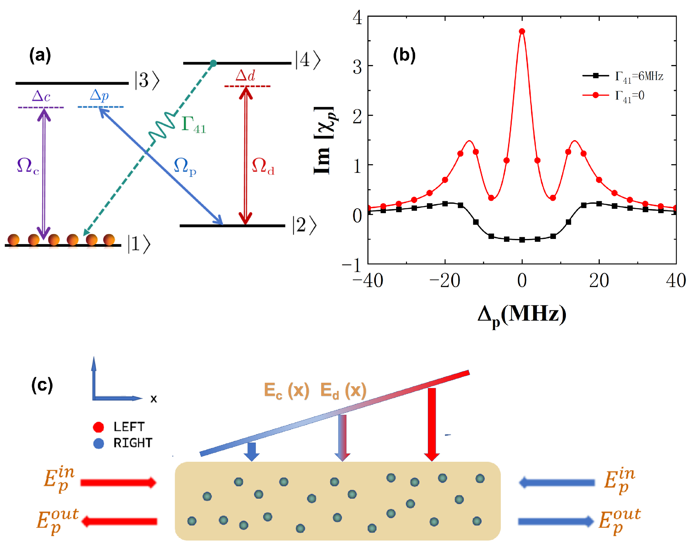
The schematic of our approach to realize nonreciprocal amplification is depicted in Figure 1a. The cold 87Rb atoms are driven into a four-level N-type system by two strong coupling fields and one probe field. The two coupling fields of the Rabi frequencies (detunings), () and (), drive the dipole-allowed transitions → and → , respectively. The probe field of the Rabi frequency (detuning), (), drives the dipole-allowed transition ↔ . The matrix element denotes the dipole moment for the transition from to . and ( and ) denote the spontaneous decay rates of the atoms transitioning from level () to levels and , respectively. Figure 1b shows the imaginary part of the probe susceptibility vs. the detuning, , with and without considering the spontaneous decay rate from level to level . Figure 1c displays the homogeneous distribution of atoms with the probe light traveling along the x-axis and the control fields traveling along the vertical x-axis. It is worth noting that we assume that the intensities of the control fields are linearly varying along the x direction, e.g., by a neutral density filter. Thus, the Rabi frequencies of the coupling can be expressed as and .
Then, based on vectors , , , and , with the electric-dipole and rotating-wave approximations, the atom-field Hamiltonian interaction in matrix form can be written as
The multi-level coherent atomic system satisfies the density operator motion equation, , where the first term on the right represents the reversible processes originating from the coherent driving fields, while the second term represents the irreversible processes originating from the spontaneous emissions. We introduce Equation (1) into the density operator motion equation and obtain the following density matrix equations:
According to the definition, element is the product of the probability amplitude of the population between states and , which indicates the state of coherence. Additionally, denotes the complex coherence dephasing rate on the transition from to , with population decay rates of and , where , 2, 3 and 4 describe the inevitable dissipation within the system, and . The above equations are constrained by , the conjugate conditions , and the steady-state condition . Under the steady-state condition , we can obtain , which is governed by the probe detuning, , and position x by numerical solution.
Finally, we can obtain the complex susceptibility of the probe field in this as follows:
where Re and Im represent the real and imaginary parts of the susceptibility, with the atomic density as a constant, corresponding to the dispersion and absorption lines of the probe beam. is the dielectric constant in vacuum and the complex refractive index .
The reflection and transmission properties of the probe field can be effectively characterized by a unimodular transfer matrix [48]. The probe susceptibility varies with position x, which leads to spatial variations in the refractive index, . Thus, we need to divide the whole sample, with length L, into sufficient thin layers (S thin layers) so that each layer can be regarded as homogeneous, with an identical thickness of . The transfer matrix of a single layer, where , can be expressed as
where the corresponding right and left reflections and transmission-complex amplitudes, and , respectively, are determined by the complex refractive index, . After that, we can write the total transfer matrices of j layers as
Note that is multiplied from left to right by layers, and is multiplied from right to left. Thus, the reflectivity of two probe fields at the jth layer, incident from the left side and right side, are given by
where and only at the ends of the sample, with a sample length of . The spatial symmetry of the susceptibility is destroyed due to the linear variation of the coupling field intensities, which leads to the nonreciprocity of the left-side and right-side reflections. This asymmetric reflection can be expressed by the contrast factor as follows:
An important figure of merit is to check the nonreciprocal reflection. We can easily determine from this factor that if , the left- and right-side reflections are nonreciprocal. And, when , we can realize unidirectional reflection.
3. Results and Discussion
In this section, we examine and discuss the nonreciprocal reflection amplification in the ingeniously designed N-type coherent atomic system. We first analyze the synchronous linear variation in the strength of two coupling fields for and . The right- and left-side reflections are plotted in Figure 2a,b with population decay rates of 6 MHz and , respectively. It is clear that there is a large region of the nonreciprocal reflection amplification corresponding to a high platform of contrast over 95% [see Figure 2c] when the transition from level to level is dipole-allowed. However, with the same parameters, the nonreciprocal reflection cannot be amplified under the condition that the transition from level to level is dipole-forbidden, corresponding to low and disordered contrast [see Figure 2d]. The physical insight is that the probe beam should be amplified in a closed-loop transition due to the presence of , as shown in Figure 1b. Specifically, as shown in Figure 1a, the atoms can be transferred from level to level by the coupling field, , and the spontaneous emission to level emits a photon with the same frequency as the probe field, . The atoms can then be transferred to level with the help of the coupling field, , along with the spontaneous emission to level . And, the nonreciprocal reflection can be achieved by simple adjustment of linear changes in the coupling field to destroy the spatial symmetry of the susceptibility.
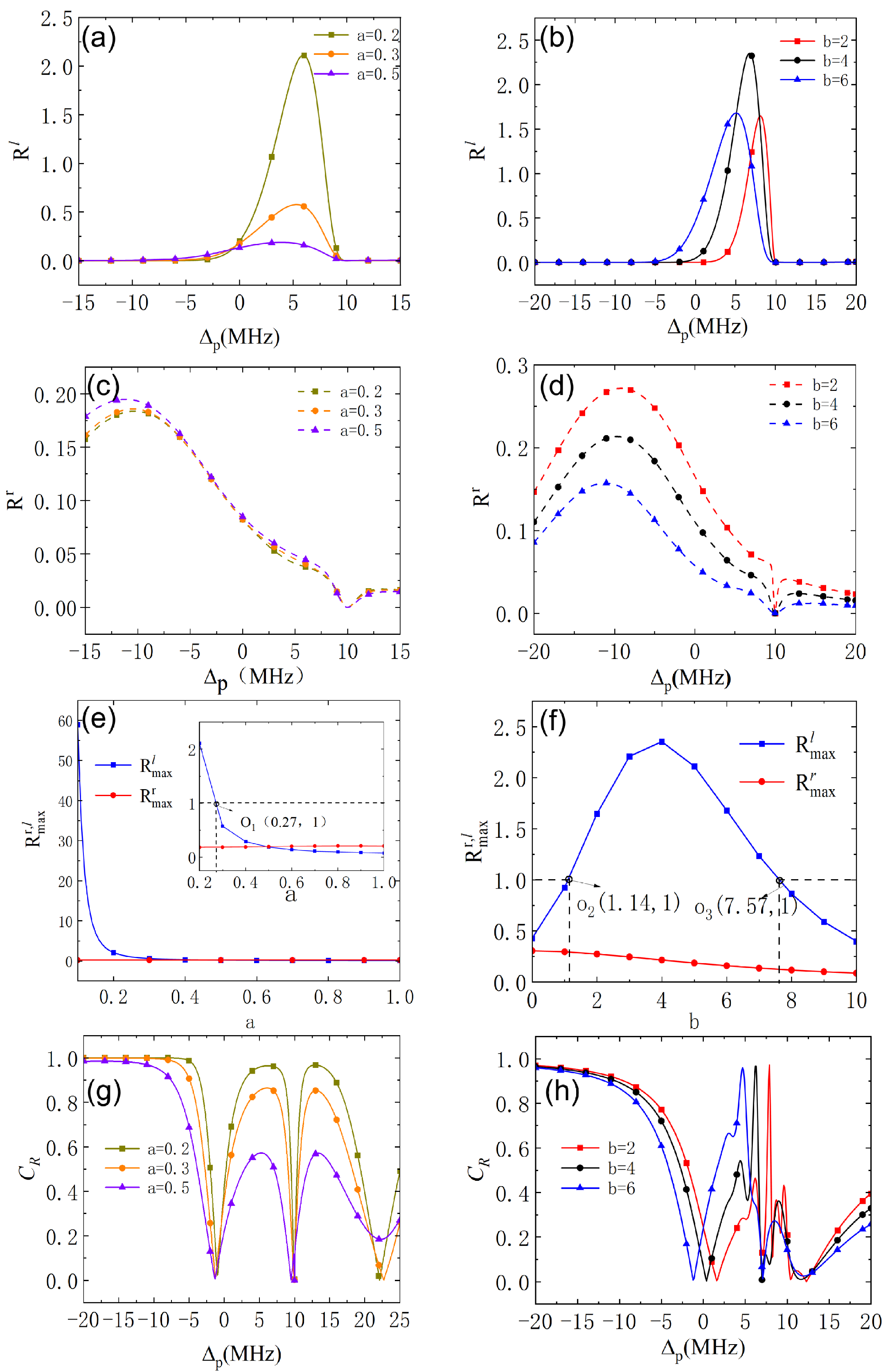
Next, we check the behavior of the nonreciprocal reflection with different linear variations in the strength of the coupling fields. As shown in Figure 3a,c, the right- and left-side reflections are nonreciprocal across a large frequency range, MHz), with varying slopes, a, and the right reflection band with rather low reflectivity is not sensitive to a. However, the left reflectivity decreases significantly with increasing a, corresponding to the rapidly reduced contrast, C [see Figure 3g]. To further investigate the best experimental parameters for the nonreciprocal reflection, we plot the maximum of the right and left reflectivities ( and ) varying with the slope, a, in Figure 3e. It is easy to see that is almost lower than , and decreases remarkably with the increased a. When , is already lower than . Especially, can be amplified until , and is well suppressed. It is of special interest to examine another parameter, b, which determines the linear variation of the coupling fields. It is clearly shown in Figure 3b,d that the height and position of the nonreciprocal reflection band can be modulated by varying b and the corresponding contrast, C [see Figure 3h]. Figure 3f further shows that the maximum of the left-side reflectivity, , first increases and then decreases with b. It can be amplified within the range and reach its maximum at . However, the maximum of the right-side reflectivity, , decreases with increased b and can drop below within the amplified region of . The physical insight is that the strength of the coupling field is too weak to induce quantum interference on the left side of the medium; however, on the right side of the medium, the rapidly increasing coupling field leads to the disruption of quantum interference. Thus, we choose and to check the characteristics of the nonreciprocal reflection amplification.
It is also interesting to investigate the nonreciprocal reflection with the linear modulation of only one coupling field, while the strength of another coupling field does not vary with position x (with the optimal parameters and ). In Figure 4a,b, it is obvious that the height and position of the high reflection band, , are very sensitive to the strength of the control fields, whereas the low reflection band, , is robust to the strength of the control fields. Specifically, is amplified more obviously for the linear variation of the control field than the linear variation of the control field , corresponding to the lower value of [compared in Figure 4c,d]. In order to check the specific impact of the control fields, we examine Figure 4e,f. It can be seen that the maximum of the left reflectivity, , first increases and then decreases with the increased coupling field when the strength of the coupling field is linearly varying. When the strength of the coupling field is linearly varying, the maximum of increases with the increased coupling field (when MHz). And, the maximum reflectivity, , is still robust and low. It can be concluded that the nonreciprocal reflection can be well amplified and modulated by the appropriate settings of the control fields.
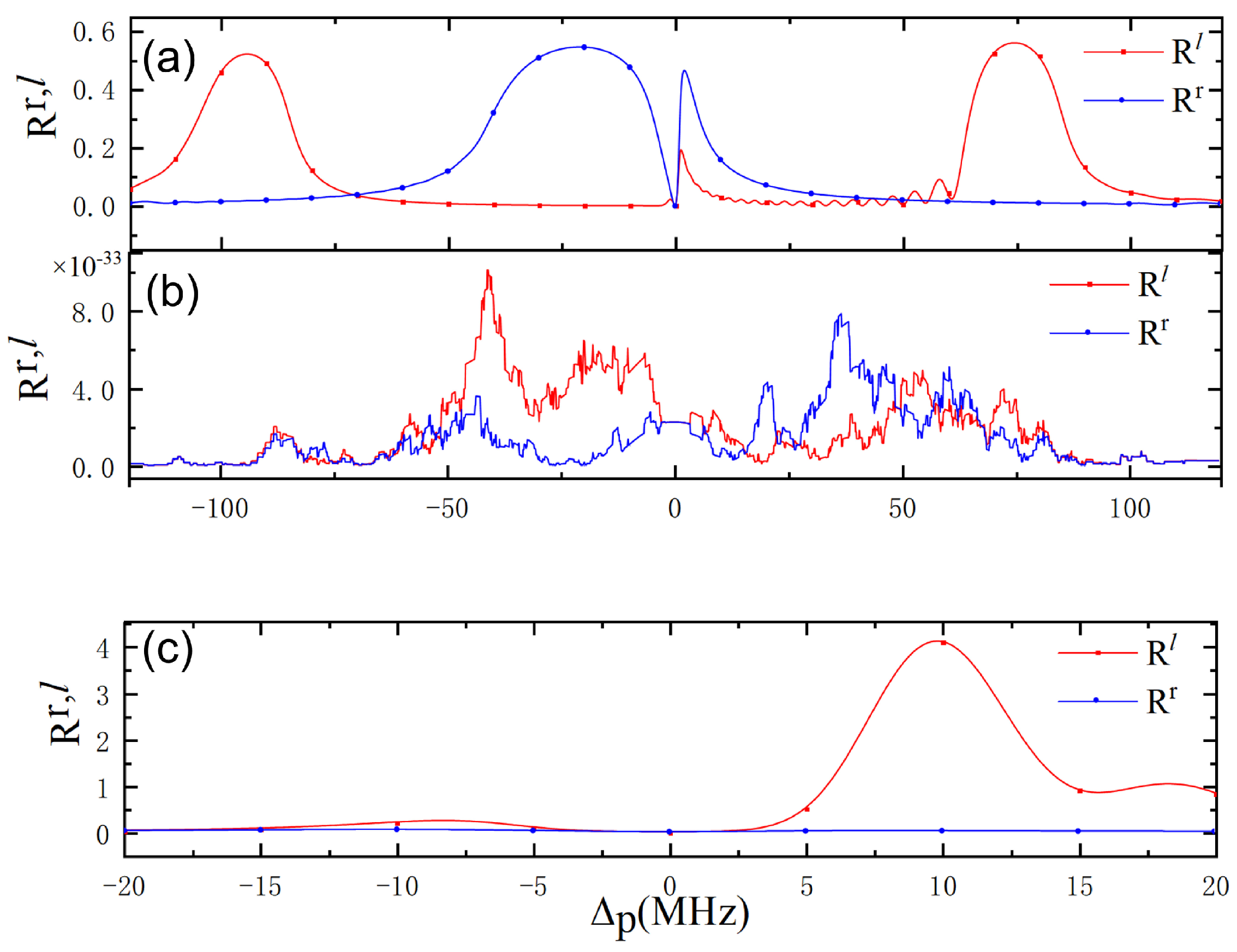
It is of special interest to check the behavior of the amplified nonreciprocal reflection with one control field closed and compare it with the case of the common linear modulation of two control fields, as shown in Figure 5. When , the N-type degenerates into a -type. There is a wide nonreciprocal reflection region () around the resonance of the probe field (except for the resonance point due to the strong transmission based on electromagnetically induced transparency) and two wide nonreciprocal reflection regions () located at large detunings, but the reflection band cannot be amplified, as clearly shown in Figure 5a. When , the N-type degenerates into a V-type, and there are two nonreciprocal reflection bands, but the right- and left-side reflectivities are rather low [see Figure 5b]. In Figure 5c, there is an almost perfect amplified nonreciprocal reflection band located in the frequency range MHz, 15 MHz). Thus, it can seen that the appropriate design of a coherent atomic system is key to achieving nonreciprocal reflection amplification, in addition to the linear modulation of the coupling field.
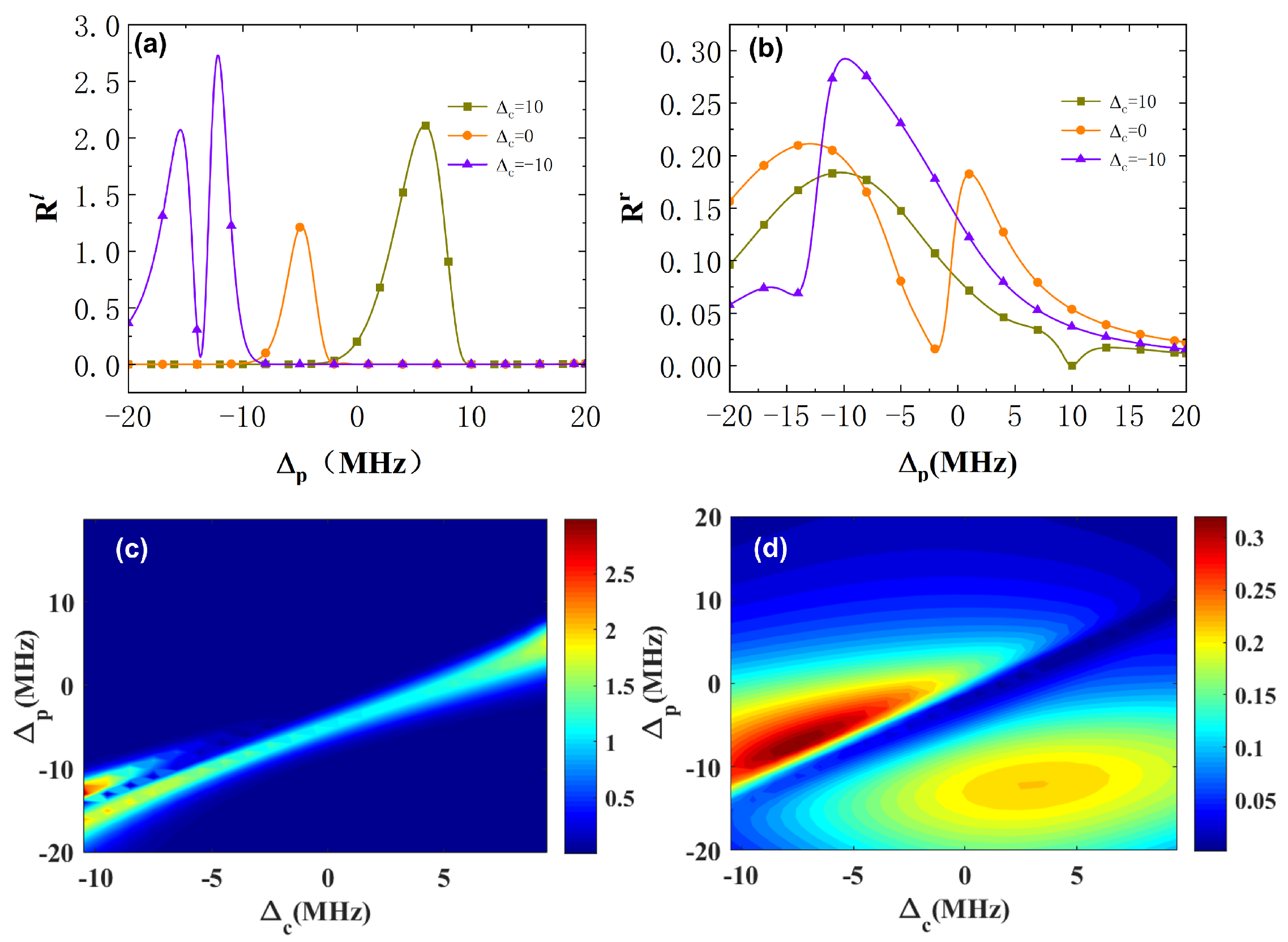
Last but not least, we then discuss the modulation of the nonreciprocal reflection amplification by the coupling detuning, . As can be seen from the results in Figure 6a,b, the frequency region of the amplified reflection band shifts with the detuning, , and the low reflectivity, , cannot form a bandgap. Further, we plot the right− and left−side reflectivities vs. and in Figure 6c,d. It is noteworthy that the strong nonreciprocity of the reflection appearing in the region , especially where the perfect nonreciprocal reflection amplification can be realized when MHz. Based on this, we can modulate the nonreciprocal reflection amplification freely by modulating .
4. Conclusions
In this paper, homogeneous distributed cold atoms arranged in a four-level N configuration are exploited to achieve nonreciprocal reflection amplification. Here, the two control fields can be linearly modulated to break the spatial symmetry of the probe susceptibility, which directly leads to the nonreciprocity of the right and left reflectivities. It is worth noting that the amplified reflection band can be achieved in the probe gain region due to the presence of spontaneous emission decay rates constructing closed-loop transitions. The numerical results show that the amplified nonreciprocal reflection band (the contrast can almost reach 1) can be modulated freely by designing the linear variation of the control fields and detunings, such as the height, the position of the amplified nonreciprocal reflection band, and even the switch between a single-color and two-color bandgap. Thus, it can be concluded that our system is rather versatile, promising to explore the amplified perfect nonreciprocal reflection. This simple and effective scheme not only amplifies the nonreciprocal reflections but also avoids many significant challenges in experiments, e.g., the complex atom-light coupling configuration, precise light-field arrangement in space, momentum conservation and phase matching, and many other factors. Therefore, our regime has potential applications in developing high-performance nonreciprocal photonic devices.
Author Contributions
Conceptualization, H.Y. and J.W.; methodology, H.Y.; software, X.L., Y.G. and G.L.; validation, X.Z. and X.L.; formal analysis, H.Y., J.W. and D.Y.; investigation, H.Y. and D.Y.; resources, X.L., Q.X. and X.Z.; data curation, X.L.; writing—original draft preparation, H.Y.; writing—review and editing, H.Y.; visualization, H.Y.; supervision, H.Y., J.W. and D.Y. All authors have read and agreed to the published version of the manuscript.
Funding
This work was supported by the Hainan Provincial Natural Science Foundation of China (Grant Nos. 121RC539, 2019RC190, and 121MS033) and the National Natural Science Foundation of China (Grant Nos. 12204137, 12126314, 12126351, and 11861031). This project was also supported by the specific research fund of The Innovation Platform for Academicians of Hainan Province (Grant Nos. YSPTZX202215 and YSPTZX202207), the Hainan Provincial Banyan Tree Foundation (Grant Nos. RSYH20231165828X and RSYH20231165827X), and the Key Laboratory of Laser Technology and Optoelectronic Functional Materials of Hainan Province.
Data Availability Statement
The data presented in this study are available on reasonable request from the corresponding authors.
Conflicts of Interest
The authors declare no conflict of interest.
References
- Hu, Y.-Q.; Qi, Y.-H.; You, Y.; Zhang, S.-C.; Lin, G.-W.; Li, X.-L.; Gong, J.-B.; Gong, S.-Q.; Niu, Y.-P. Passive nonlinear optical isolators by passing dynamic reciprocity. Phys. Rev. A 2021, 16, 014046. [Google Scholar]
- KIttlaus, E.A.; Otterstrom, N.T.; Kharel, P.; Gertler, S.; Rakich, P.T. Non-reciprocal interband Brillouin modulation. Nat. Photon. 2018, 12, 613. [Google Scholar]
- Fan, S.; Shi, Y.; Lin, Q. Nonreciprocal Photonics without Magneto-Optics. IEEE Antennas Wirel. Propag. Lett. 2018, 17, 1948. [Google Scholar]
- Sounas, D.L.; Alu, A. Non-reciprocal photonics based on time modulation. Nat. Photon. 2017, 11, 774. [Google Scholar]
- Xia, K.-Y.; Lu, G.-W.; Lin, G.-W.; Cheng, Y.-Q.; Niu, Y.-P.; Gong, S.-Q.; Twamley, J. Reversible nonmagnetic single-photon isolation using unbalanced quantum coupling. Phys. Rev. A 2014, 90, 043802. [Google Scholar]
- Hu, Y.-Q.; Zhang, S.-C.; Qi, Y.-H.; Lin, G.-W.; Niu, Y.-P.; Gong, S.-Q. Multiwavelength magnetic-free optical isolator by optical pumping in warm atoms. Phys. Rev. Lett. 2019, 12, 054004. [Google Scholar]
- Shi, Y.; Yu, Z.-F.; Fan, S.-H. Limitations of nonlinear optical isolators due to dynamic reciprocity. Nat. Photon. 2015, 9, 388. [Google Scholar]
- Mailis, S. On-chip non-magnetic optical isolator. Nat. Photon. 2021, 5, 794. [Google Scholar]
- Xue, M.; Tong, H.; Dong, H.; Wang, M. Saturated Gain-Induced Non-Reciprocal Transmission and Broadband On-Chip Optical Isolator. Photonics 2024, 11, 261. [Google Scholar] [CrossRef]
- Jalas, D.; Petrov, A.; Eich, M.; Freude, W.; Fan, S.; Yu, Z.; Baets, R.; Popović, M.; Melloni, A.; Joannopoulos, J.D.; et al. What is- and what is not- an optical isolator. Nat. Photon. 2013, 7, 579. [Google Scholar]
- Shen, H.-Z.; Wang, Q.; Wang, J.; Yi, X.-X. Nonreciprocal unconventional photon blockade in a driven dissipative cavity with parametric amplification. Phys. Rev. A 2020, 101, 013826. [Google Scholar] [CrossRef]
- Zhang, S.-C.; Hu, Y.-Q.; Lin, G.-W.; Niu, Y.-P.; Xia, K.-Y.; Gong, J.-B.; Gong, S.-Q. Thermal-motion-induced non-reciprocal quantum optical system. Nat. Photon. 2018, 12, 744. [Google Scholar]
- Dong, M.-X.; Xia, K.-Y.; Zhang, W.-H.; Yu, Y.-C.; Ye, Y.-H.; Li, E.-Z.; Zeng, L.; Ding, D.-S.; Shi, B.-S.; Guo, G.-C.; et al. All-optical reversible single-photon isolation at room temperature. Sci. Adv. 2021, 7, eabe8924. [Google Scholar] [PubMed]
- Yang, H.; Qin, G.-Q.; Zhang, H.; Mao, X.; Wang, M.; Long, G.-L. Multimode interference induced optical nonreciprocity and routing in an optical microcavity. Ann. Der Phys. 2021, 533, 2000506. [Google Scholar]
- Yang, P.-F.; Xia, X.-W.; He, H.; Li, S.-K.; Han, X.; Zhang, P.; Li, G.; Zhang, P.-F.; Xu, J.-P.; Yang, Y.-P.; et al. Realization of nonlinear optical nonreciprocity on a few-photon level based on atoms strongly coupled to an asymmetric cavity. Phys. Rev. Lett. 2019, 123, 233604. [Google Scholar] [PubMed]
- Huang, R.; Miranowicz, A.; Liao, J.Q.; Nori, F.; Jing, H. Nonreciprocal photon blockade. Phys. Rev. Lett. 2018, 121, 153601. [Google Scholar] [PubMed]
- Shen, Z.; Zhang, Y.-L.; Chen, Y.; Zou, C.-L.; Xiao, Y.-F.; Zou, X.-B.; Sun, F.-W.; Guo, G.-C.; Dong, C.-H. Experimental realization of optomechanically induced non-reciprocity. Nat. Photon. 2016, 10, 657. [Google Scholar]
- Tang, L.; Tang, J.-S.; Chen, M.-Y.; Nori, F.; Xiao, M.; Xia, K.-Y. Quantum squeezing induced optical nonreciprocity. Phys. Rev. Lett. 2022, 128, 083604. [Google Scholar] [PubMed]
- Tang, J.-S.; Nie, W.; Tang, L.; Chen, M.-Y.; Su, X.; Lu, Y.-Q.; Nori, F.; Xia, K.-Y. Nonreciprocal Single-Photon Band Structure. Phys. Rev. Lett. 2022, 128, 203602. [Google Scholar]
- Ji, X.; Pan, P.; Huang, S.; Chen, A. Optical Nonreciprocity in Double Optomechanical Systems with Quadratic Coupling. Photonics 2022, 9, 728. [Google Scholar] [CrossRef]
- Wang, D.-W.; Zhou, H.-T.; Guo, M.-J.; Zhang, J.-X.; Evers, J.; Zhu, S.-Y. Optical Diode Made from a Moving Photonic Crystal. Phys. Rev. Lett. 2013, 110, 093901. [Google Scholar] [PubMed]
- Horsley, S.-A.-R.; Wu, J.-H.; Artoni, M.; La Rocca, G.-C. Dynamically induced two-color nonreciprocity in a tripod system of a moving atomic lattice. Phys. Rev. Lett. 2013, 110, 223602. [Google Scholar] [CrossRef] [PubMed]
- Cao, Q.-T.; Wang, H.-M.; Dong, C.-H.; Jing, H.; Liu, R.-S.; Chen, X.; Ge, L.; Gong, Q.-H.; Xiao, Y.-F. Experimental demonstration of spontaneous chirality in a nonlinear microresonator. Phys. Rev. Lett. 2017, 118, 033901. [Google Scholar] [PubMed]
- Wang, Q.; Xu, F.; Yu, Z.; Qian, X.; Hu, X.; Lu, Y.; Wang, H.-T. A bidirectional tunable optical diode based on periodically poled LiNbO3. Opt. Express 2010, 18, 7340–7346. [Google Scholar] [CrossRef] [PubMed]
- Miroshnichenko, A.E.; Brasselet, E.; Kivshar, Y.S. Reversible optical nonreciprocity in periodic structures with liquid crystals. Appl. Phys. Lett. 2010, 96, 063302. [Google Scholar]
- Wu, J.-H.; Artoni, M.; La Rocca, G.-C. Perfect absorption and no reflection in disordered photonic crystals. Phys. Rev. A 2017, 95, 053862. [Google Scholar]
- Tian, S.-C.; Wan, R.-G.; Wang, L.-J.; Shu, S.-L.; Lu, H.; Zhang, X.; Tong, C.-Z.; Feng, J.-L.; Xiao, M.; Wang, L.-J. Asymmetric light diffraction of two-dimensional electromagnetically induced grating with PT symmetry in asymmetric double quantum wells. Opt. Express 2018, 26, 32918. [Google Scholar] [PubMed]
- Wu, J.-H.; Artoni, M.; La Rocca, G.-C. Non-Hermitian degeneracies and unidirectional reflectionless atomic lattices. Phys. Rev. Lett. 2014, 113, 123004. [Google Scholar] [CrossRef] [PubMed]
- Horsley, S.-A.-R.; Longhi, S. Spatiotemporal deforma-tions of reflectionless potentials. Phys. Rev. A 2017, 96, 023841. [Google Scholar]
- Horsley, S.-A.-R.; Artoni, M.; La Rocca, G.-C. Spatial Kramers–Kronig relations and the reflection of waves. Nat. Photon. 2015, 9, 436. [Google Scholar]
- Baek, Y.; Park, Y. Intensity-based holographic imaging via space-domain Kramers-Kronig relations. Nat. Photon. 2021, 15, 354–360. [Google Scholar]
- Lee, C.; Baek, Y.; Hugonnet, H.; Park, Y. Single-shot wide-field topography measurement using spectrally multiplexed reflection intensity holography via space-domain Kramers-Kronig relations. Opt. Lett. 2022, 47, 1025–1208. [Google Scholar] [PubMed]
- Li, Q.; Luo, Y.; Liu, D.; Gao, Y.; Zhang, J.; Ran, L.; Ye, D.-X. A miniaturized anechoic chamber: Omnidirectional impedance matching based on truncated spatial Kramers-Kronig medium. Adv. Opt. Mater. 2022, 10, 2200381. [Google Scholar]
- Jiang, W.; Ma, Y.-G.; Yuan, J.; Yin, G.; Wu, W.-H.; He, S.-L. Deformable broadband metamaterial absorbers engineered with an analytical spatial Kramers-Kronig permittivity profile. Laser Photonics Rev. 2017, 11, 1600253. [Google Scholar]
- Zheng, D.-D.; Zhang, Y.; Liu, Y.-M.; Zhang, X.-J.; Wu, J.-H. Spatial Kramers-Kronig relation and unidirectional light reflection induced by Rydberg interactions. Phys. Rev. A 2023, 107, 013704. [Google Scholar]
- Zhang, Y.; Wu, J.-H.; Artoni, M.; La Rocca, G.-C. Controlled unidirectional reflection in cold atoms via the spatial kramers-kronig relation. Opt. Express 2021, 29, 5890–5900. [Google Scholar] [PubMed]
- Pei, X.-S.; Zhang, H.-X.; Pan, M.-M.; Geng, Y.; Li, T.-M.; Yang, H. Two-color unidirectional reflections by modulating the spatial susceptibility in a homogeneous atomic medium. Opt. Express 2023, 31, 14694. [Google Scholar] [PubMed]
- Lin, G.-W.; Zhang, S.-C.; Hu, Y.-Q.; Niu, Y.-P.; Gong, J.-B.; Gong, S.-Q. Nonreciprocal Amplification with Four-Level Hot Atoms. Phys. Rev. Lett. 2019, 123, 033902. [Google Scholar]
- Fang, K.; Luo, J.; Metelmann, A.; Matheny, M.H.; Marquardt, F.; Clerk, A.A.; Painter, O. Generalized non-reciprocity in an optomechanical circuit via synthetic magnetism and reservoir engineering. Nat. Phys. 2017, 13, 465. [Google Scholar] [CrossRef]
- Shen, Z.; Zhang, Y.-L.; Chen, Y.; Sun, F.-W.; Zou, X.-B.; Guo, G.-C.; Zou, C.-L.; Dong, C.-H. Reconfigurable optomechanical circulator and directional amplifier. Nat. Commun. 2018, 9, 1797. [Google Scholar]
- Song, L.-N.; Zheng, Q.; Xu, X.-W.; Jiang, C.; Li, Y. Optimal unidirectional amplification induced by optical gain in optomechanical systems. Phys. Rev. A 2019, 100, 043835. [Google Scholar]
- Peng, R.; Zhang, W.-Z.; Chao, S.-L.; Zhao, C.-G.; Yang, Z.; Yang, J.-Y.; Zhou, L. Unidirectional amplification in optomechanical system coupling with a structured bath. Opt. Express 2022, 30, 21649–21663. [Google Scholar] [PubMed]
- Abdo, B.; Sliwa, K.; Frunzio, L.; Devoret, M. Directional amplification with a Josephson circuit. Phys. Rev. X 2013, 3, 031001. [Google Scholar]
- de las Heras, A.M.; Carusotto, I. Unidirectional lasing in nonlinear Taiji micro-ring resonators. Phys. Rev. A 2021, 104, 043501. [Google Scholar]
- Jiang, Y.; Maayani, S.; Carmon, T.; Nori, F.; Jing, H. Nonreciprocal Phonon Laser. Phys. Rev. Appl. 2018, 10, 064037. [Google Scholar] [CrossRef]
- Jin, L. Asymmetric lasing at spectral singularities. Phys. Rev. A 2018, 97, 033840. [Google Scholar]
- Geng, Y.; Pei, X.-S.; Li, G.-R.; Lin, X.-Y.; Zhang, H.-X.; Yan, D.; Yang, H. Spatial susceptibility modulation and controlled unidirectional reflection amplification via four-wave mixing. Opt. Express 2023, 31, 38228–38239. [Google Scholar]
- Artoni, M.; La Rocca, G.-C.; Bassani, F. Resonantly absorbing one-dimensional photonic crystals. Phys. Rev. E 2005, 72, 046604. [Google Scholar]
Figure 1.
(a) Energy- level diagram of a closed-loop four-level N-type atomic system driven by a weak probe field and two strong coupling fields with the help of the spontaneous emission decay rate, ; (b) The probe susceptibility vs. the detuning, , with and without spontaneous decay rates of MHz (black solid line with squares) and (red solid line with circles); (c) Diagram of the homogeneous atomic medium illuminated by two coupling fields, and , along the vertical x axis, with a probe field traveling along the x direction. The other parameters are the same as in Figure 2.

Figure 2.
(a,b) The reflectivities of the left side, (red solid line with stars), and right side, (blue solid line with squares), vs. the detuning, . The corresponding contrast factor vs. the detuning, , in (c,d), with different spontaneous decay rates of MHz in (a,c) and in (b,d). The other parameters are cm−3, MHz, , , , , , , C·m, and MHz.

Figure 3.
(a,c) The reflectivities of the left side, , and right side, , vs. the detuning, , with different slopes, a, and the corresponding contrast in (g); (e) The maximum reflectivities of the left side, , and right side, , vs. the slope, a; (b,d) The reflectivities of the left side, , and right side, , vs. the detuning, , with varying b, and the corresponding contrast in (h); (f) The maximum reflectivities of the left side, , and right side, , vs. b. The other parameters are the same as in Figure 2.

Figure 4.
(a,c) The reflectivities of the left side, , and right side, , vs. the detuning, , with MHz, 10 MHz, and 15 MHz; (e) The maximum reflectivities of the left side, , and right side, , vs. the coupling field, , with the linear variation of the coupling field ; (b,d) The reflectivities of the left side, , and right side, , vs. the detuning, , with MHz, 15 MHz, and 20 MHz; (f) The maximum reflectivities of the left side, , and right side, , vs. the coupling field, , with the linear variation of the control field . The other parameters are the same as in Figure 2.

Figure 5.
The reflectivities of the left side, , and right side, , vs. the detuning, , with closed and in (a), with closed and in (b), and with in (c). The other parameters are the same as in Figure 2.
Figure 5.
The reflectivities of the left side, , and right side, , vs. the detuning, , with closed and in (a), with closed and in (b), and with in (c). The other parameters are the same as in Figure 2.

Figure 6.
(a,b) The reflectivities of the left side, , and right side, , vs. the detuning, , corresponding to the coupling detunings MHz, 0, and −10 MHz; (c,d) The reflectivities of the left side, , and right side, , vs. the detunings and , respectively, with linear variation of the coupling field and the constant coupling field MHz. The other parameters are the same as in Figure 2.

Disclaimer/Publisher’s Note: The statements, opinions and data contained in all publications are solely those of the individual author(s) and contributor(s) and not of MDPI and/or the editor(s). MDPI and/or the editor(s) disclaim responsibility for any injury to people or property resulting from any ideas, methods, instructions or products referred to in the content. |
© 2024 by the authors. Licensee MDPI, Basel, Switzerland. This article is an open access article distributed under the terms and conditions of the Creative Commons Attribution (CC BY) license (https://creativecommons.org/licenses/by/4.0/).
Share and Cite
MDPI and ACS Style
Lin, X.; Zheng, X.; Geng, Y.; Li, G.; Xu, Q.; Wu, J.; Yan, D.; Yang, H. Amplified Nonreciprocal Reflection in a Uniform Atomic Medium with the Help of Spontaneous Emissions. Photonics 2024, 11, 389. https://doi.org/10.3390/photonics11040389
AMA Style
Lin X, Zheng X, Geng Y, Li G, Xu Q, Wu J, Yan D, Yang H. Amplified Nonreciprocal Reflection in a Uniform Atomic Medium with the Help of Spontaneous Emissions. Photonics. 2024; 11(4):389. https://doi.org/10.3390/photonics11040389
Chicago/Turabian StyleLin, Xinyu, Xinfu Zheng, Yue Geng, Guanrong Li, Qiongyi Xu, Jinhui Wu, Dong Yan, and Hong Yang. 2024. "Amplified Nonreciprocal Reflection in a Uniform Atomic Medium with the Help of Spontaneous Emissions" Photonics 11, no. 4: 389. https://doi.org/10.3390/photonics11040389
Note that from the first issue of 2016, this journal uses article numbers instead of page numbers. See further details here.