Article

Design of a Label-Free, Distributed Bragg Grating Resonator Based Dielectric Waveguide Biosensor

1
Laboratory of Biosensors and Bioelectronics (LBB), Swiss Federal Institute of Technology ETH, Gloriastrasse 35, Zürich CH-8092, Switzerland
2
CSEM Centre Suisse d'Electronique et de Microtechnique SA, Bahnhofstrasse 1, Landquart CH-7302, Switzerland
3
Optics Balzers AG, Neugrüt 35, Balzers FL-9496, Liechtenstein
4
University of Applied Sciences and Technology NTB, Werdenbergstrasse 4, Buchs CH-9470, Switzerland
5
CSEM Centre Suisse d'Electronique et de Microtechnique SA, Rue Jaquet-Droz 1, Neuchâtel CH-2002, Switzerland
*
Author to whom correspondence should be addressed.
Photonics 2015, 2(1), 124-138; https://doi.org/10.3390/photonics2010124
Submission received: 24 December 2014 / Accepted: 22 January 2015 / Published: 29 January 2015

Abstract

:
In this work, we present a resonant, dielectric waveguide device based on distributed Bragg gratings for label-free biosensing applications. The refractive index sensitive optical transducer aims at improving the performance of planar waveguide grating sensor systems with limited Q-factor and dynamic range by combing the advantages of resonant cavities, such as a multitude of resonance peaks with high finesse, with the manageable complexity of waveguide grating couplers. The general sensor concept is introduced and supported by theoretical considerations as well as numerical simulations based on Coupled Mode Theory. In contrast to a single Bragg grating reflector, the presented Fabry-Pérot type distributed Bragg resonator exhibits an extended measurement range as well as relaxed fabrication tolerances. The resulting, relatively simple sensor structure can be fabricated with standard lithographic means and is independent of expensive light-sources and/or detectors, making an affordable but sensitive device, potentially suitable for point-of-care applications.

Graphical Abstract

1. Introduction

Biosensors are widely used in various fields such as pharmaceutical industry, healthcare, biotechnology, food, feed and environmental monitoring to detect the interaction, presence and concentration of (bio)molecules and exist in numerous configurations. Dielectric waveguide based sensors represent a subgroup of highly sensitive optical transducer elements, mainly applied for label-free biosensing [1,2,3,4]. Compared to labeled methods, such as fluorescent based sensing methods, in label-free detection the molecules do not have to be functionalized with a marker element, which is a benefit since the functionalization with fluorescent labels can be expensive, laborious and can alter the structure and hence the molecules’ characteristics. Yet still, in general, label-free methods are less sensitive than labeled ones [5].
To overcome this disadvantage, many promising and highly sensitive interferometers as well as resonator based integrated optical transducers have been presented to increase the sensitivity and lower the limit of detection of label-free devices. Countless examples can be found in [6,7,8,9,10]. Sophisticated micro-sphere, disc and ring resonator sensors with low limit of detection (LoD) and high quality factors (Q-factor) have been realized but seem not to be suitable for volume production due to their high level of complexity regarding fabrication and light coupling. In contrast, grating based waveguide sensors can be batch produced by standard lithographic means and light can easily be coupled via the diffractive grating itself, but exhibit lower Q-factors and therefore higher LoD [11]. In this work, we introduce a distributed Bragg grating resonator waveguide biosensor, combining the simplicity of grating couplers with a high finesse and extended dynamic range of resonant cavities. Compared to fiber Bragg gratings (FBG), the presented planar structure can be fabricated as well as read-out in parallel at a higher integration density, important drivers regarding price and multiplexing.

1.1. Background and Motivation

In its simplest configuration, a planar waveguide sensor has a three layer structure with a high refractive index film F between the optically less dense supporting substrate S and the investigated cover medium C. The high refractive dielectric waveguide film acts as a conduit of the propagating light by means of total internal reflection. Light will be guided if the propagating mode fulfills the following condition [12]:
2 k h f n f 2 n e f f 2 + φ f c + φ f s = 2 π m w g
where k = 2π⁄λ is the wavenumber, λ the wavelength of the propagating light, hf and nf the waveguide film height and refractive index, respectively, the effective refractive index neff, which is defined as neff = c/vp with vp denoting the phase velocity of the guided mode and c the vacuum speed of light, φfc and φfs the Fresnel reflection phase shifts at the film-cover and film-substrate interface, respectively, and the waveguide mode number mwg. Depending on the waveguide configuration, only a discrete number of guided modes mwg = 0,1,2,… is supported within the structure. For single-mode waveguides, the right-hand side of Equation (1) reduces to zero. As the Fresnel reflections phase shifts φfc and φfs differ for transverse electric (TE) and transverse magnetic (TM) waves, neff is polarization dependent and is directly proportional to the propagation constant of the guided mode. Due to the mode overlap (evanescent field) of the propagating light into the cover and substrate in close proximity to the waveguide interface, any refractive index change at the sensor surface alters the phase velocity of the guided mode and therefore neff, which can be detected by optical transducers as described below.
In the case of a waveguide grating coupler, a periodically corrugated grating region in the waveguide can be used as a light coupling region, for both in and out-coupling from the waveguide (Figure 1). This coupling region is very sensitive to refractive index changes and is often used as a sensor [13]. Changes in the cover refractive index nc in close proximity to the sensor surface, e.g., by the adsorption of (bio)molecules with unequal refractive index than the displaced aqueous medium, alter the effective refractive index neff. Since the coupling condition is defined as
n c / s   s i n ( θ c ) = n e f f m g λ Λ
with the grating period Λ, grating diffraction order mg and nc/s the refractive indices of the cover or substrate, respectively, depending on which side of the waveguide is considered, any changes in neff can be monitored by changes in the coupling angle Δθc or a wavelength shift Δλshift [13]. Various interrogation schemes for waveguide grating sensors have been reported based on angular as well as spectral detuning.
While Equation (2) holds true for infinitely extended and shallow gratings illuminated by a perfect plane wave, actual sensors with finite grating depth and length exhibit broadened resonances and therefore a limited Q-factor [14,15]. For these finite structures, an effective grating length Leff can be defined, which is inversely proportional to the spectral broadening δ λ F W H M C G of the resonance peak of waveguide grating couplers [15,16]:
δ λ F W H M C G = λ Λ π 1 L e f f
The resulting resonance curve with a finite width can, for instance, be interrogated by a narrowband, vertical cavity surface emitting laser diode (VCSEL) by constantly tuning the wavelength of the in-coupled light and subsequent out-coupling via a second grating onto a photosensitive detector, as applied in [17] (Figure 1). Due to the VCSEL’s limited tuning range ΔλVCSEL of approximately 2 nm, the measurement range is also limited within rather narrow bounds, often not sufficient for the detection of larger refractive index shifts, such as caused by larger molecules or sandwich immunoassays.
Figure 1. Schematic representation of a wavelength interrogated waveguide grating coupler and the associated sensing principle: a coherent beam is coupled into the waveguide F via a first grating with period Λ and length Lin and coupled out of the latter via a subsequent grating (left). The resonance condition is interrogated via spectral tuning of the light source and monitoring of the corresponding intensity of the out-coupled light. Refractive index changes Δnc in the cover medium C lead to a shift of the resonance curve by Δλshift. Vertical cavity surface emitting laser (VCSEL) interrogated waveguide grating couplers exhibit a limited spectral width δ λ F W H M C G as well as a limited measurement range (right).
Photonics 02 00124 g001
An approach to overcome the first limitation of waveguide grating couplers, namely the limited finesse, is to decouple the angular contribution of the resonance condition from the spectral, e.g., by Bragg gratings. Planar Bragg grating waveguide sensors possess an analogous structure, but instead of coupling light in or out of the waveguide, a certain spectral region of the propagating mode will be reflected within the waveguide, again depending on neff [18]. The refractive index changes, induced by the quantity to be measured, can be monitored either by the wavelength shift of the entire stop-band or a sharp fringe at its edge by measuring the reflected or transmitted light [19]. Spectral interrogation of such a structure can again be accomplished either by a wide-tunable laser and a photodiode or a broad-band light source in combination with a spectrum analyzer. The downside of both approaches is the relatively high initial costs for abovementioned equipment, a hurdle for point-of-care or handheld devices. Even though the tunable light source could consist of an inexpensive VCSEL, its limited tuning range would require stringent manufacturing tolerances to the sensor to ensure spectral overlap of the laser’s tuning range and the Bragg grating's stop-band edges.
Here, we present the concept and numerical simulations of a Fabry-Pérot type distributed Bragg resonator (DBR) waveguide biosensor with a multitude of high-Q resonance peaks within a broad stop-band. As we shall show, the additional resonance peaks, with free spectral range smaller than the tuning range of the laser, ease the manufacturing tolerances, decrease production costs and increase the dynamic range of the sensor element. The optical transducer is designed as such that no additional effort is required to directly replace the sensor chip of current wavelength interrogated waveguide grating sensors and hereby improving the overall system performance.

2. Sensor Elements and Design Considerations
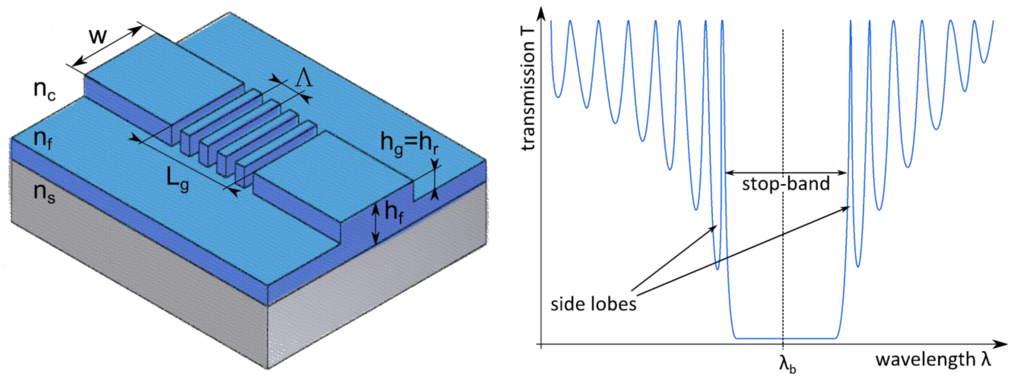
The proposed sensor consists of a light source, a waveguide, two grating couplers, a Fabry-Pérot resonator between two Bragg grating reflectors (DBR’s) and finally a photosensitive detector (Figure 2). A similar, silicon-based structure has been introduced by Grieco et al. as a bistable optical element [20], but not for sensing purposes. Hereinafter, only the DBR sensor and its elements are described in more detail, since the coupling gratings do not act as the sensitive elements but only facilitate the coupling of the light into the waveguide. Despite the increased sensor performance, the structure can be fabricated by the same, standard lithographic means as applied for waveguide grating couplers, which is described in more detail in [17]. The design is driven by considering a tunable VCSEL as interrogating light source.
Figure 2. Schematic representation of the sensor (top and side view), comprising a coherent source (S), coupling gratings (CG), Bragg gratings (BG), a resonator (R) and a detector (D).
Photonics 02 00124 g002

2.1. Bragg grating

Fiber Bragg gratings are optical elements with spatially, periodically varying refractive indices and are extensively used in telecommunication, but also as temperature, strain, pressure, current and (bio)chemical sensors [21]. Said variation of the effective refractive index can be accomplished, e.g., by direct writing of photo-induced, local refractive index changes or waveguide surface. Bragg gratings are not limited to optical fibers but can also be integrated in planar waveguide structures a at a high integration density. Contrary to grating couplers, Bragg gratings back-reflect a certain wavelength within the waveguide instead of coupling it in our out. This so-called Bragg wavelength λb is defined as [18]:
q b λ b = 2 n e f f Λ
where qb accounts for the Bragg order (for sensing applications, usually qb = 1). Effective refractive index changes ∆neff can therefore directly be measured by a Bragg wavelength shift ∆λb. A schematic illustration of such a device and a typical transmission spectrum with Bragg wavelength λb, stop-band and its side lobes is depicted in Figure 3.
Figure 3. Schematic representation of the considered, planar waveguide based Bragg grating reflector (left) with the rib width w and height hr, substrate, film and cover refractive indices ns, nf, nc, grating length Lg, period Λ and depth hg, respectively. A typical transmission spectrum of a Bragg reflector at Bragg wavelength λb is plotted on the right-hand side, highlighting the stop-band and its side lobes.
Photonics 02 00124 g003
As mentioned in the introduction, to measure refractive index shifts, the interrogation of the entire stop-band requires relatively costly equipment or entails stringent manufacturing tolerances to design the sensor as such that the interrogation laser’s wavelength matches the Bragg wavelength respectively the edge of the first side lobe of the gratings spectral response. The proposed structure thus envisages the implementation of a subsequent, secondary Bragg grating, hereby forming an optical cavity or Fabry-Pérot resonator.

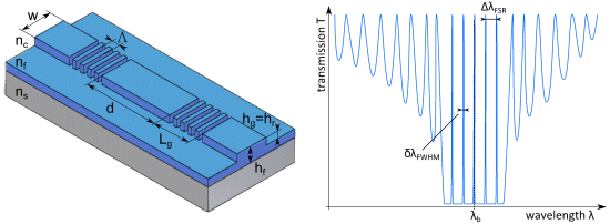
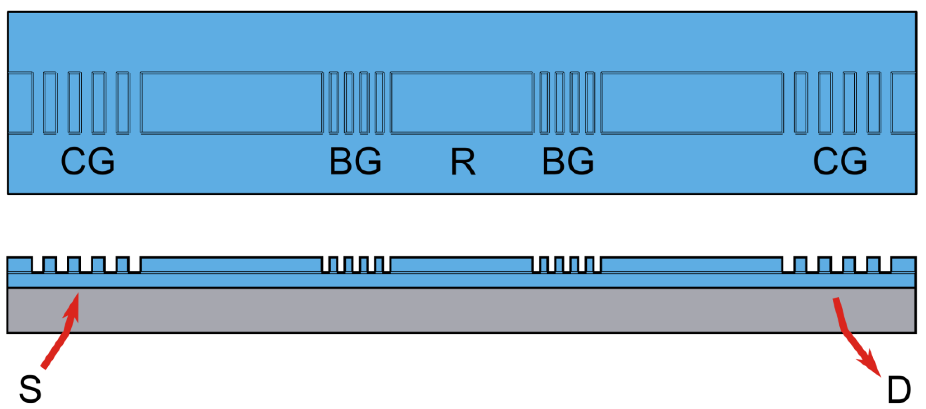
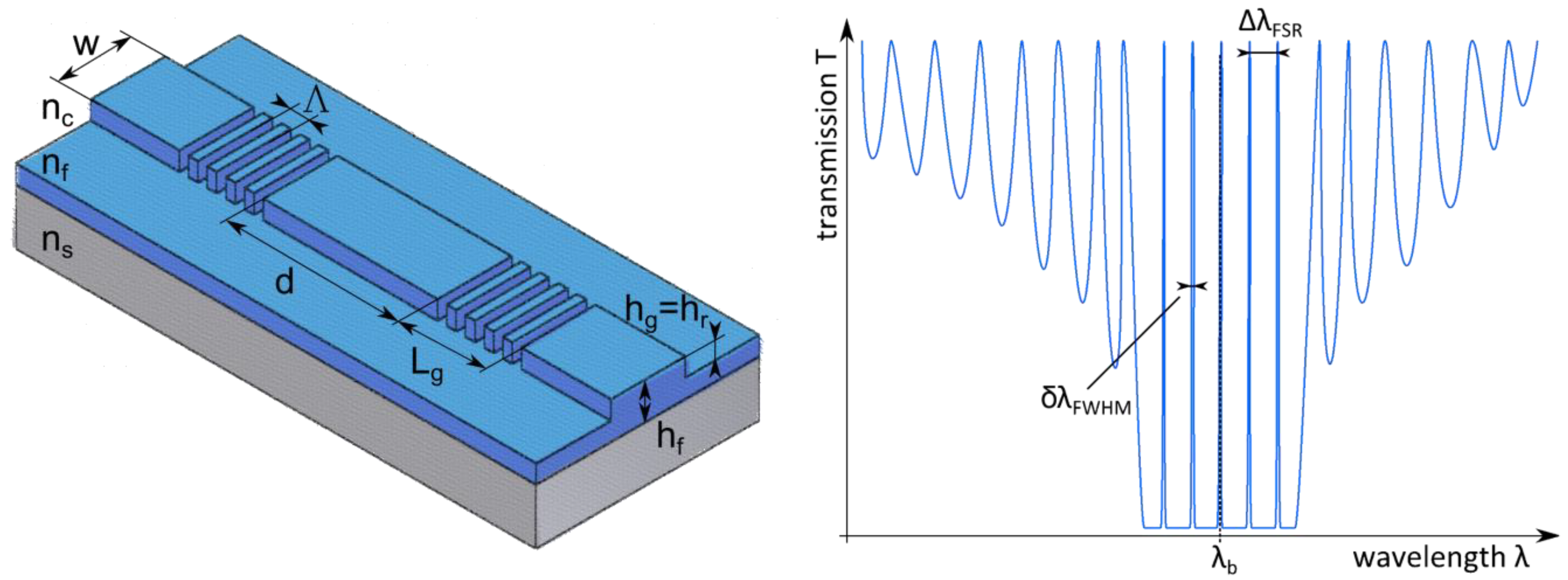
2.2. Fabry-Pérot Resonator

A Fabry-Pérot resonator is an optical oscillator and consists of two spaced reflectors [22]. In the proposed sensor design, the reflectors comprise of corrugated Bragg gratings and the resonator in between of an unstructured waveguide (Figure 4). Due to the high reflectivity of the reflectors, incident light is reflected forwards and backwards within the resonator, thereby creating a stationary wave within the cavity which gives rise to a multitude of resonance peaks within the stop band. The spectral distance between the resonance peaks is called free spectral range (FSR) and the spectral width of the peak can be express via the full width at half maximum (FWHM). The resonator’s FSR and FWHM can be calculated as follows:
Δ λ F S R = λ 0 2 n e f f r   d
δ λ F W H M F P = λ 0 2 π n e f f r   d 1 R R
with the resonator’s effective refractive index n e f f r .
A characteristic value of a resonator is its finesse , which is defined as the quotient of the abovementioned FSR between the resonance peaks and the FWHM of the latter.
= Δ φ F S R δ φ F W H M = Δ λ F S R δ λ F W H M = π R 1 R
Whereas the finesse describes times the number of back and forth reflections within the resonator cavity, the quality factor or Q-factor represents the optical energy stored in the device, particularly times the ratio of the stored over the dissipated energy per round-trip of the oscillating mode and is defined as the resonance wavelength λm of the corresponding mode m divided by its resonance width:
Q = λ m δ λ m
For high sensor performances and low LoDs, high Q-factors are favored since resonant modes with narrower linewidth are more efficient in filtering spectral noise [23]. According to White et al., the standard deviation of the resulting spectral variation σ can be approximated by:
σ δ λ F W H M 4.5 ( S N R 0.25 )
with the signal-to-noise ratio (SNR) of the resonance peak. Still, the smallest detectable wavelength shift Δλmin and therefore the experimental LoD is depending on the measurement setup, e.g., its spectral resolution and thermal stability, as explained in more detail in the subsequent section and in [23]. A thoroughly elaborated contribution on the LoD can be found in [24].
Figure 4. Schematic representation of the introduced, planar waveguide based Bragg grating resonator structure (left) with the resonator length d, rib width w and height hr, substrate, film and cover refractive indices ns, nf, nc, grating length Lg, period Λ and depth hg, respectively. The desired transmission spectrum of the Bragg grating resonator at Bragg wavelength λb is illustrated on the right-hand side, highlighting the free spectral range ΔλFSR and full width at half maximum (FWHM) δλFWHM.
Photonics 02 00124 g004
Compared to a waveguide grating coupler or a single Bragg grating reflector, the implementation of a second grating and the formation of an optical cavity have the advantage to introduce a multitude of resonance peaks with a high finesse within the stop-band of the Bragg grating (Figure 4). The FSR of said peaks can easily be defined by the resonator length (Equation (5)). Preferably, the FSR should be smaller than the tunable range of the interrogating laser source. Additionally, the Q-factor of the cavity can easily be tuned via the Bragg grating length, as evinced by Equations (6) and (8).

2.3. Sensor Sensitivity

The goal is to design a sensor with maximal sensitivity but small FWHM. As described by Ciminelli et al. [6], the minimal detectable bulk refractive index change Δnmin is
Δ n m i n = m 2 d ( n e f f n c ) 1 Δ λ m i n
and for surface sensing, the minimal detectable mass ΔMmin, where M=ρAt, ρ the surface mass density, A the sensor surface area and the adsorbed molecule layer thickness t,
Δ M m i n = ρ A m 2 d ( n e f f t ) 1 Δ λ m i n
Since the ratio m/2d is constant at a given wavelength, the minimal detectable refractive index change Δnmin is independent of the resonator length d due to the linear scaling with the cavity mode order m [25]. On the other hand, the minimal detectable mass ΔMmin depends on the sensing area A. Therefore, the smaller the sensing area A and hence the resonator length d of the device, the smaller the minimal detectable mass ΔMmin.
Nonetheless, to ensure overlap of the device spectrum with the tuning range of the proposed interrogating VCSEL laser ΔλVCSEL and considering Equations (5) and (11), the optimal resonator length dopt is given by
d o p t = λ b 2 2 n e f f r Δ λ V C S E L
Together with Equations (9)–(11) it becomes evident that a low LoD is the result of the combination of large wavelength shifts Δλshift per cover refractive index change ∆nc (or more general the sensitivity S = Δλ⁄∆nc ) in combination with a small FWHM. The higher the sensitivity and the Q-factor, the lower the LoD. In order to compare the different designs, the figure of merit (FoM) value can be calculated with
F o M = Δ λ s h i f t Δ n c δ λ F W H M   F P   =   S δ λ F W H M   F P
High FoMs lead to lower LoDs since smaller spectral shifts can be detected due to the narrow linewidth [6,23]. The LoD can be expressed as the ratio between the sensor resolution R and its sensitivity S:
L o D =   R S
Whereas the sensitivity S is an inherent property of the sensor chip itself, the resolution R highly depends on the interrogating reader platform and its individual noise contributions, such as spectral variations induced due to amplitude noise (Equation (9)), temperature induced noise as well as the finite spectral resolution of the detector [23]. Since the presented optical transducer is designed to be interrogated by the same measurement platform as the waveguide grating coupler introduced in [17], therefore with identical thermal and detector noise contributions, the improved finesse directly lowers the spectral variation and hence the LoD of the sensor system.
In general, the complexity as well as the demands on fabrication tolerances and light sources increase with increasing Q-factors. With the proposed DBR approach and a FSR in the range of a cost effective light source, this issues can be overcome, although the fabrication of the devices is not more demanding than for waveguide grating couplers.

3. Methods

Based on the aforementioned statements and considering state-of-the-art, high volume manufacturing capabilities, commercially available VCSEL lasers and dielectric waveguide materials, the DBR sensor design has been optimized by numerical simulations using Coupled Mode Theory (CMT(using the RSoftTM module GratingMODTM from Synopsys® (Mountain View, United States))) [26]. The input parameters for the calculation of the envisaged design were a VCSEL laser at 850 nm central emission wavelength, with a bandwidth δλVCSEL of 100 MHz and a laser tuning range ΔλVCSEL of 2 nm, a glass substrate with a refractive index of ns = 1.5156 (Schott D263®eco, Schott AG, Mainz, Germany), a tantalum-pentoxide Ta2O5 waveguide film with a refractive index of nf = 2.097 (Optics Balzers AG, Balzers, Liechtenstein) and a cover refractive index of nc = 1.329 [27], assuming an aqueous cover solution, all at 850 nm. All dielectric materials were considered to be lossless media. The choice of materials and the related refractive indices are based on the waveguide grating coupler described in [17], a standard product of the co-authoring company Optics Balzers, to directly compare its performance with the investigated, novel structure. Besides Ta2O5 and amongst others, suitable waveguide materials would include titanium-dioxide TiO2, silicon nitride Si3N4 or silicon. The sensitivity towards homogeneous sensing of the devices was evaluated by numerically increasing the cover refractive index ∆nc by 0.005 and investigating the magnitude of the corresponding spectral shift ∆λshift.

4. Results

4.1. Sensitivity and Figure of Merit

A standard waveguide grating coupler as described in [17] with a film thickness hf of 150 nm, refractive indices as abovementioned in chapter 3 and listed in Table 1 and a grating period Λ of 360 nm illuminated at 850 nm (TM polarization) has been simulated. The spectral shift due to a cover refractive index increase ∆nc by 0.005 resulted in ∆λshift = 379 pm. Therefore, together with a spectral width (Equation (3)) of δ λ F W H M C G = 108 pm, the FoM for this waveguide grating coupler is approximately 702.
Subsequently, considering the aforementioned design criteria and the configuration depicted in Figure 3, a rib-waveguide based single-mode TM structure with a single Bragg grating with its central wavelength at 850 nm was simulated, resulting in a grating period Λ of 274.5 nm. The remaining parameters of the sensor design a result of a multi-parameter scan and are listed in Table 1 and illustrated in Figure 3. The presented sensor design underlines the basic concept and does not claim to be most sensitive configuration. The resulting transmission spectrum of the single Bragg grating reflector sensor for two different cover refractive indices is shown in Figure 5 (left). Increasing the cover refractive index ∆nc by 0.005 resulted in a calculated shift ∆λshift of the first stop-band edge peak of 512.9 pm. With a spectral side lobe peak-width δλFWHM of 346.2 pm, the presented design exhibits a simulated FoM of 296. The result has been validated by numerically confirming the measurements from Pham et al. [19], whose presented device possesses (based on our calculations) a FoM of 730, therefore a similar FoM as for waveguide grating couplers.
Table 1. Input Parameters for Simulation of the BG Reflector and Resonator.
ParameterSymbolBG ReflectorBG Resonator
Rib widthw1 µm1 µm
Rib heighthr40 nm40 nm
Waveguide thicknesshf160 nm160 nm
Grating lengthLg100 µm2 × 50 µm
Grating widthw1 µm1 µm
Grating depthhg40 nm40 nm
Grating periodΛ274.5 nm272 nm
Resonator lengthd-100 µm
Refractive index of substratens1.51561.5156
Refractive index of waveguidenf2.0972.097
Refractive index of cover (water)nc1.3291.329
Refractive index change of coverΔnc0.0050.005
The next step was then to introduce a second Bragg grating to form a resonant cavity, whereas the resonator length d was given by Equation (12), while keeping all the other parameters fixed to the one of the previous model with only a single Bragg reflector. The outcome of the simulation can be seen in Figure 5 (right). As desired, the device's spectral response reveals the additional, high-Q resonance peaks within the stop-band with a FSR ΔλFSR of 1.96 ± 0.02 nm, which is smaller than tuning range ΔλVCSEL of the laser as desired, and a FWHM δλFWHM down to 3.9 pm for the central peak. The shift of the resonance peaks due to the raise of cover refractive index ∆nc of 0.005 was calculated to be 624.2 pm. Hence, the resulting FoM of the proposed resonant design is approximately 32’010.
Figure 5. Calculated transmission spectra of the Bragg grating reflector (left) and Bragg grating resonator (right) structure and the associated spectral shift due to a cover refractive index change ∆nc of 0.005 (blue, solid line: nc = 1.329, red, dashed line: nc = 1.335).
Photonics 02 00124 g005

4.2. Measurement Range and Fabrication Tolerances

Besides the higher FoM due to the increased finesse and sensitivity for the resonator compared to the single reflector design, the additional resonance peaks within the stop-band help, on the one hand, to bridge the 2 nm tuning range of the VCSEL laser and therefore increase the transducers dynamic range (Figure 6). On the other hand, fabrication tolerances of the sensor chip can be eased since any of the resonance peaks can be present within the tuning range of the VCSEL laser and not strictly the one of side lobes of the stop band, as it is the case for the single reflector. This not only affects the chip but also the VCSEL tolerances due to a relatively large batch to batch variation regarding the central emission wavelength.
The theoretical dynamic range regarding cover refractive index of the Bragg grating reflector has been calculated to span from ∆nc = 1.329 – 1.347 = 0.018. At any higher or lower cover refractive index, the edge of the stop-band is out of the tuning range of the considered laser diode. In the case of the proposed Bragg grating resonator, an adjacent resonance peak will appear in the wavelength range under investigation as soon as the first one is about to leave the latter. Due to this feature, the dynamic range towards cover refractive index reaches from ∆nc = 1.305 – 1.400 = 0.095, or 528% of the single Bragg reflector.
Regarding the fabrication tolerances of the Bragg grating reflector, the film thickness hf for instance needs to be within a narrow and for volume production critical window of 160 nm to 164 nm or within 4 nm, if all the other parameters are regarded as constant and exact. Not only the waveguide thickness, but also its refractive index nf is subject to some batch to batch variation. For the Bragg reflector type, the acceptable film refractive index ranges from 2.097 to 2.102 and needs to be therefore within rather demanding 0.005. For the Bragg grating resonator, a traceable resonance peak would still be within the detection window even if the film thickness hf varies between 157.5 nm to 175.0 nm or within 17.5 nm or if the film refractive index spans from 2.084 to 2.102 or within 0.018. The same holds true for the Bragg grating period. With a fabrication tolerance of ±0.2nm for the grating period Λ by interference lithography, the calculated grating period Λ of 274.5 nm as listed in Table 1 for the Bragg grating reflector would require to be within a challenging range of 0.6 nm to ensure the presence of a stop-band side lobe within the interrogation spectrum of the laser source. Due to the multiple, traceable peaks of the resonant Bragg grating sensor, the tolerance for the grating period Λ could be relaxed to 2.8 nm.
Figure 6. The additional resonance peaks within the stop-band help to bridge the 2 nm tuning range of the VCSEL laser ∆λVCSEL increase the transducers dynamic range and ease the fabrication tolerances. Whereas large spectral shifts ∆λshift may not be measured with the Bragg grating reflector since the peak shifts out of the detection window (left), an adjacent peak appears in the lasers’ tuning range in case of the Bragg grating resonator (right).
Photonics 02 00124 g006

5. Discussion

The goal of the present study was to introduce and simulate a Bragg grating based waveguide biosensor with manageable fabrication efforts and independence of expensive interrogation equipment by formation of a resonant cavity. The numerical results clearly support the envisaged sensor features, namely a multitude of resonant cavity modes with a higher finesse and sensitivity then waveguide grating couplers in combination with a smaller FSR than the tuning range of the laser. The extended dynamic range of the sensor can be regarded as an additional benefit, as an adjacent resonance peak will appear in the tuning range of the laser if the monitored peak shifts out of the latter due to a significant refractive index change (Figure 6). Additionally, besides the abundance of tunable VCSEL lasers at 850 nm, interrogation at shorter wavelengths (850 nm instead of 1550 nm like Pham et al. [19]) benefit from an increased surface to bulk sensitivity ratio [28].
Compared to other resonant devices, not only fabrication but also light coupling is rather easy and therefore suitable to substitute current waveguide grating coupler chips in wavelength interrogated sensing systems. Furthermore, due to its linear structure, the waveguide is not subject to neither bending losses and nor to any bus waveguide noise. Nonetheless, high quality monomode waveguides will be crucial since losses due to scattering as well as absorption might lower the device's Q-factor and hence its FoM.

6. Conclusion

The concept, design and numerical simulations of a label-free, distributed Bragg grating resonator biosensor have been introduced. With the disclosed structure, certain shortcomings such as limited dynamic range and finesse, e.g., for waveguide grating couplers, or stringent fabrication tolerances for high-Q waveguide based sensors can be avoided, which is a result of a linear; distributed Bragg grating based resonator structure with a multitude of narrow resonance peaks with extended measurement range. Standard lithographic means for sensor production as well as independence of expensive light-sources and/or detectors make up an interesting concept for an affordable but sensitive device, and are also potentially suitable for point-of-care applications.

Author Contributions

The presented work is a product of the intellectual environment of the whole team and all members have contributed in various degrees to the conducted research. Florian Kehl conceived the initial sensor concept and wrote the manuscript, David Bischof and Mirjad Keka jointly performed the numerical simulations of the devices, whereas Markus Michler and Ross Stanley contributed to the work through their scientific expertise and by critically reviewing its content.

Acknowledgments

Financial support by the Swiss Commission for Technology and Innovation (CTI) is gratefully acknowledged (CTI project No 13865.2 PFNM-NM).

Conflict of Interest

The authors declare no conflict of interest.

References

  1. Cooper, M.A. Optical Biosensors in drug discovery. Nat. Rev. Drug Discov. 2002, 1, 515–528. [Google Scholar] [CrossRef]
  2. Pasche, S.; Wenger, B.; Ischer, R.; Giazzon, M.; Angeloni, S.; Voirin, G. Integrated optical biosensor for in-line monitoring of cell cultures. Biosens. Bioelectron. 2010, 26, 1478–1485. [Google Scholar] [CrossRef] [PubMed]
  3. Bier, F.F.; Schmid, R.D. Real time analysis of competitive binding using grating coupler immunosensors for pesticide detection. Biosens. Bioelectron. 1994, 9, 125–130. [Google Scholar] [CrossRef]
  4. Vörös, J.; Graf, R.; Kenausis, G.L.; Bruinink, A.; Mayer, J.; Textor, M.; Wintermantel, E.; Spencer, N.D. Feasibility study of an online toxicological sensor based on the optical waveguide technique. Biosens. Bioelectron. 2000, 15, 423–429. [Google Scholar] [CrossRef] [PubMed]
  5. Matthew, A. Cooper. In Label-Free Biosensors: Techniques and Applications; Cambridge University Press: Cambridge, UK, 2009. [Google Scholar]
  6. Ciminelli, C.; Campanella, C.M.; Dell’Olio, F.; Campanella, C.E.; Armenise, M.N. Label-free optical resonant sensors for biochemical applications. Prog. Quantum Electron. 2013, 37, 51–107. [Google Scholar] [CrossRef]
  7. Schmitt, K.; Oehse, K.; Sulz, G.; Hoffmann, C. Evanescent field sensors based on tantalum pentoxide waveguides–a review. Sensors 2008, 8, 711–738. [Google Scholar] [CrossRef]
  8. Kozma, P.; Kehl, F.; Ehrentreich-Förster, E.; Stamm, C.; Bier, F.F. Integrated planar optical waveguide interferometer biosensors: A comparative review. Biosens. Bioelectron. 2014, 58, 287–307. [Google Scholar] [CrossRef] [PubMed]
  9. Estevez, M.C.; Alvarez, M.; Lechuga, L.M. Integrated optical devices for lab‐on‐a‐chip biosensing applications. Laser Photon. Rev. 2012, 6, 463–487. [Google Scholar] [CrossRef] [Green Version]
  10. Vahala, K.J. Optical microcavities. Nature 2003, 424, 839–846. [Google Scholar] [CrossRef] [PubMed]
  11. Wang, Q.; Zhang, D.; Wang, Z.; Huang, Y. Optimizing the quality factor of a wideband guided-mode resonance biosensor. Appl. Phys. A 2014, 117, 553–556. [Google Scholar] [CrossRef]
  12. Tamir, T. Guided-Wave Optoelectronics; Springer-Verlag: Berlin, Germany, 1988. [Google Scholar]
  13. Nellen, P.M.; Tiefenthaler, K.; Lukosz, W. Integrated optical input grating couplers as biochemical sensors. Sens. Actuators 1988, 15, 285–295. [Google Scholar] [CrossRef]
  14. Kunz, R.E.; Dübendorfer, J.; Morf, R.H. Finite grating depth effects for integrated optical sensors with high sensitivity. Biosens. Bioelectron. 1996, 11, 653–667. [Google Scholar] [CrossRef]
  15. Brazas, J.C.; Li, L. Analysis of input-grating couplers having finite lengths. Appl. Opt. 1995, 34, 3786–3792. [Google Scholar] [CrossRef] [PubMed]
  16. Norton, S.M.; Erdogan, T.; Morris, G.M. Coupled-mode theory of resonant-grating filters. JOSA A 1997, 14, 629–639. [Google Scholar] [CrossRef]
  17. Cottier, K.; Wiki, M.; Voirin, G.; Gao, H.; Kunz, R.E. Label-free highly sensitive detection of (small) molecules by wavelength interrogation of integrated optical chips. Sens. Actuators B: Chem. 2003, 91, 241–251. [Google Scholar] [CrossRef]
  18. Hill, K.O.; Meltz, G. Fiber Bragg grating technology fundamentals and overview. J. Lightwave Technol. 1997, 15, 1263–1276. [Google Scholar] [CrossRef]
  19. Pham, S.V.; Dijkstra, M.; Hollink, A.J.F.; Kauppinen, L.J.; de Ridder, R.M.; Pollnau, M.; Lambeck, P.V.; Hoekstra, H.J.W.M. On-chip bulk-index concentration and direct, label-free protein sensing utilizing an optical grated-waveguide cavity. Sens. Actuators B: Chem. 2012, 174, 602–608. [Google Scholar] [CrossRef]
  20. Grieco, A.; Slutsky, B.; Tan, D.T.; Zamek, S.; Nezhad, M.P.; Fainman, Y. Optical bistability in a silicon waveguide distributed Bragg reflector Fabry–Perot resonator. J. Lightwave Technol. 2012, 30, 2352–2355. [Google Scholar] [CrossRef]
  21. Lee, B. Review of the present status of optical fiber sensors. Optic. Fiber Technol. 2003, 9, 57–79. [Google Scholar] [CrossRef]
  22. Vaughan, M. The Fabry-Perot Interferometer: History, Theory, Practice and Applications; CRC press: Boca Raton, USA, 1989. [Google Scholar]
  23. White, I.M.; Fan, X. On the performance quantification of resonant refractive index sensors. Opt. Express 2008, 16, 1020–1028. [Google Scholar] [CrossRef] [PubMed]
  24. Loock, H.P.; Wentzell, P.D. Detection limits of chemical sensors: Applications and misapplications. Sens. Actuators B: Chem. 2012, 173, 157–163. [Google Scholar] [CrossRef]
  25. De Vos, K.; Bartolozzi, I.; Schacht, E.; Bienstman, P.; Baets, R. Silicon-on-Insulator microring resonator for sensitive and label-free biosensing. Opt. Express 2007, 15, 7610–7615. [Google Scholar] [CrossRef] [PubMed]
  26. Huang, W.P. Coupled-mode theory for optical waveguides: An overview. JOSA A 1994, 11, 963–983. [Google Scholar] [CrossRef]
  27. Hale, G.M.; Querry, M.R. Optical constants of water in the 200-nm to 200-µm wavelength region. Appl. Opt. 1973, 12, 555–563. [Google Scholar] [CrossRef] [PubMed]
  28. Ganesh, N.; Block, I.D.; Cunningham, B.T. Near ultraviolet-wavelength photonic-crystal biosensor with enhanced surface-to-bulk sensitivity ratio. Appl. Phys. Lett. 2006, 89, 023901. [Google Scholar] [CrossRef]

