Improved Magneto-Optic Surface Plasmon Resonance Biosensors


1
Department of Electrical Engineering & Computer Science, York University, Toronto, ON M3J 1P3, Canada
2
Department of Physics and Astronomy, York University, Toronto, ON M3J 1P3, Canada
3
GEM Systems Inc., Markham, ON L3R 5H6, Canada
*
Author to whom correspondence should be addressed.
Photonics 2018, 5(3), 15; https://doi.org/10.3390/photonics5030015
Submission received: 11 April 2018
/
Revised: 10 June 2018
/
Accepted: 20 June 2018
/
Published: 22 June 2018
(This article belongs to the Special Issue Biomedical Photonics Advances)
Abstract
:The magneto-optic (MO) characteristics and sensing performance of noble metal (Ag, Au, Cu) or transition metal (Fe, Ni, Co) single layers and Ag/Co or Au/Co bilayers have been studied and compared in both the standard plasmonic and MO plasmonic configurations at two different wavelengths (632.8 nm and 785 nm) and in two different sensing media (air and water). The sensing performance is found to be medium-specific and lower in biosensor-relevant water-based media. The sensitivities of MO-SPR sensors is found to be superior to SPR sensors in all cases. This enhancement in sensitivity means the detection limit of this class of transducers can be substantially improved by tuning Au/Co layer thickness, wavelength, and incident angle of optical radiation. The optimized bilayer showed an enhancement in sensitivity by over 30× in air and 9× in water as compared to the conventional Au SPR configuration. Notably, the best performance is 3× above that of MO-SPR sensors coupled to a photonic crystal previously reported in the literature and is found when the ferromagnetic layer is furthest from the sensing medium, as opposed to typical MO-SPR configurations. This proposed structure is attractive for next-generation biosensors.

1. Introduction
Most metals and their alloys and multilayers support surface plasmons (SP) when in contact with dielectrics such as gases (air, He, etc.), liquids (water, saliva, etc.), or solids (glass, etc.) [1,2,3,4]. One necessary condition to generate a surface plasmon is a change in sign in the real part of the dielectric function at the interface. Surface plasmons can be excited by electromagnetic radiation—when the radiation frequency matches that of the surface plasmons, a resonance condition takes place, known as surface plasmon resonance (SPR). Besides the need to match the frequency/wavelength, the excitation condition needs a suitable geometry to match the momentum. This matching condition can be achieved using appropriately designed excitation platforms such as the Kretschmann [5], Otto [6], and grating coupler [7] geometries. The Kretschmann geometry is commonly used for exciting SPRs due to its simplicity in terms of fabrication, assembly, and handling purposes. Since SPRs are localized to an interface and are associated with evanescent, exponentially decaying electromagnetic fields, their propagation is very sensitive to the dielectric environment near the interface. This feature makes SPR transducers particularly well suited for the detection of subtle changes in refractive index in the dielectric medium above the metal layer. For biosensing, this translates to the possibility of detecting the changes in refractive index associated with the binding or reaction of biomolecules with suitable receptors present on the metal surface.
Nanoscale layers of noble/ferromagnetic metals support surface plasmons when in contact with a dielectric, and their excitations leading to resonance [8,9,10]. Under externally applied magnetic fields, ferromagnetic layers can be readily used to tune SPRs, as the dielectric tensor of the ferromagnet changes as function of the applied magnetic field. Additionally, the magnitude of the magneto-optic Kerr effect increases substantially under SP resonance conditions, leading to a magneto-optic SPR (MO-SPR) sensor that has higher sensitivity than its SPR counterpart [11,12,13,14,15,16,17,18,19,20]. Hence ferromagnetic multilayers can be employed as transducers for sensing biological specimens [8,11,15,19,21,22]. Their importance stems not only from the fact that they support SPRs but because of the possibility of combining and optimizing these structures in various combinations, compositions, and thicknesses to tune and enhance the sensitivity of the sensor.
Over the last decade, several kinds of surface plasmon resonance configurations have been proposed for biosensing [11,23,24]. The uniqueness of these sensing platforms includes label-free biosensing, fast response leading to real time detection of molecular interaction kinetics, high sensitivity, and the possibility of developing automated data acquisition and processing systems. Despite all these advantages and the current presence of commercialized biosensing systems for drug discovery, plasmonic based sensing platforms still possess several challenges, limiting their practical applications. These challenges include: degradation of the sensor surface because of the difficulty of removing adsorbed materials and damaging the sensor surface during surface cleaning. Additionally, the SPR performance has been optimized but is not sufficient for applications such as early disease detection or broad-spectrum screening, as the samples are either very dilute or have low volume. The sensitivity performance not only depends intrinsically on the sensor characteristic but is also a function of bio-layer thickness and type of receptor/molecule interaction exploited.
The sensitivity of the biosensor can be defined in different ways, depending generally on the sensor response characteristics or mode of excitation [25]. Commonly, SPR biosensors are benchmarked through their angular sensitivity, where the shift of the resonant angle of incidence provides a measurement of molecular binding events onto the sensor surface [11,23,26]. The molecular binding gives rise to a change in the effective index of refraction in the medium near the sensor surface, which in turn affects the SPR resonance angle. To decouple the optical activity of the molecular interactions from the sensor intrinsic performance, a practical sensitivity metric relates changes in resonance angle to changes in refractive index units (RIU) in the sensing medium. Likewise, sensitivity of the MO-SPR based biosensors can also be defined in different ways [19,21], but these typically differ from those associated with SPR sensors due to the different sensing mechanism. Due to the various ways to characterize both types of biosensors, direct comparison of the performance of SPR and MO-SPR based sensors can be limited. Here we adopt new sensitivity metrics that can be used to compare SPR and MO-SPR sensor performance directly and independently of the biomolecular interaction. More details on sensitivity metrics are given in Section 3.
The detection limit, which is defined as, D = σ/S, where σ is the standard deviation of the noise of the sensor and S is the sensitivity of the sensor, can be strongly enhanced through various modulation and detection techniques. These include modulating the wavelength and angle of incidence of the probe light, as well as amplitude and phase modulation [23]. In MO-SPR sensors an externally applied magnetic field, H, is modulated to enhance D [8,14,27,28].
Traditional SPR sensors are based on Au and Ag layers due to their low propagation losses, leading to narrow resonance linewidths. The detection limit for this kind of sensing platform is 10−4 to 10−6 RIU (depending on wavelength and if modulation approaches are employed) [23], where the sensitivity depends on two factors: the slope of the measured SPR spectra and shift of the curve with refractive index. Magnetic multilayer structures can be employed as transducer to tune MO activity in the SPR configuration [12,29]. The introduction of the ferromagnetic layer (e.g., Co) leads to an increase in the MO activity. However, this leads to a decrease in sensitivity of the sensor due to increased propagation losses. The challenge is to optimize between MO activity and SPR linewidth to obtain an MO-SPR response that is superior to SPR. Furthermore, MO-SPR sensors have shown very promising detection limits when combined with photonic crystals to enhance their performance, theoretically as low as 7 × 10⁻⁸ RIU in the optimal condition [12].
We have recently reported microstructure and magneto-optic SPR of nano-scale Co/Ag and Co/Au multilayers [22,30]. This work models thicker (up to 50 nm) noble metals Au, Ag, and Cu and their combination with thicker (up to 8 nm) ferromagnetic Fe, Co, and Ni layers in an SPR transducer configuration to study the effect of Co layer thickness to achieve optimal MO-SPR configuration. Both variations in optical excitation wavelength and probed medium (air and water, the latter being more relevant to biosensing applications) are taken into consideration in the analysis. We show that the optimized sensor configuration leads to a detection limit below that of state-of-the-art sensors. Notably, the optimal configurations shown here are different than those previously reported, in that they include the ferromagnetic layer far from the sensing surface, rather than within 10 nm from the surface as in most MO-SPR studies [12,31,32].
2. Materials and Methods
A transfer-matrix formalism was used in Lumerical FDTD to model the excitation of surface plasmons. The MO effects for ferromagnetic materials were modeled by finite off-diagonal components of the complex permittivity tensor [11]. The magneto-optic coefficients were set to zero in the absence of an applied magnetic field and set to literature values under the influence of a saturating magnetic field [31]. The various dimensional and optical parameters used in the calculations are given in Table 1.
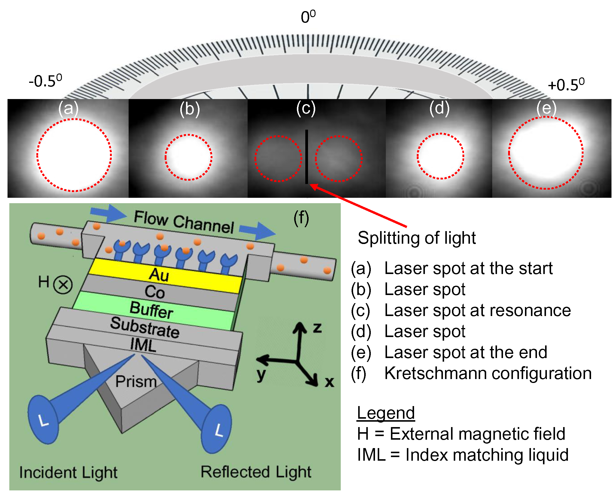
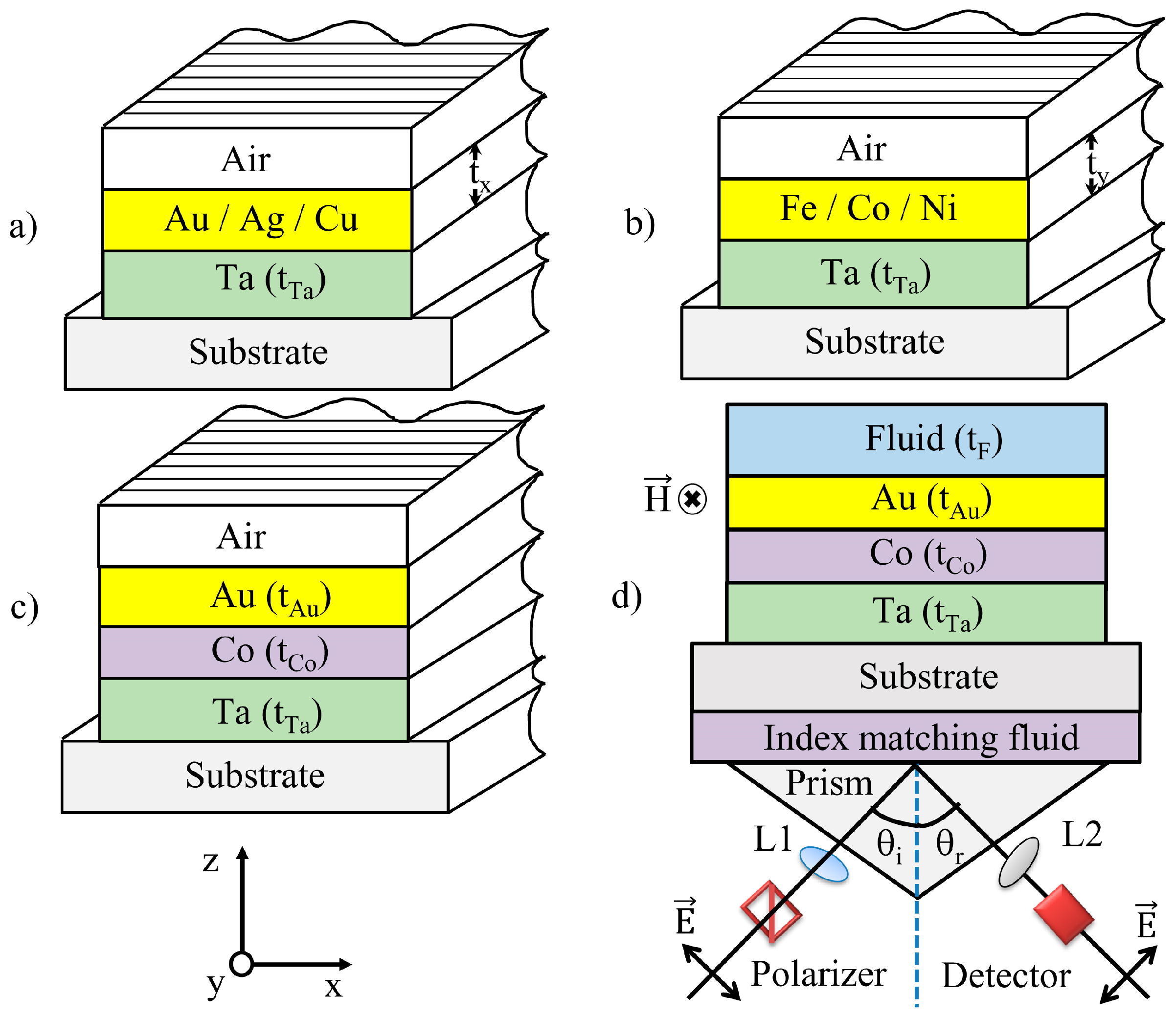
Figure 1a–d show schematics of four typical SPR transducer configurations modeled in this study and how they are considered in a system inclusive of sample and detection system. The first two structures (a,b) consist of single layers of noble metals Au, Ag or Cu (tAu,Ag,Cu = 35 nm) or single layers of ferromagnets Co, Fe, Ni (tCo,Fe,Ni = 8 nm). The last two structures (c,d) consist of bilayers of Co (tCo) and Au (tAu) with gas (air, Helium) or liquid (water, methanol) as the medium being probed, respectively. The detection configuration is also shown in (d) (Kretschmann configuration). For the study of the Co/Ag or Co/Cu systems, the Au (tAu) layers in (c,d) were replaced by Ag (tAg) or Cu (tCu) while keeping all other parameters unchanged.
The substrate considered was BK-7 glass. In each case, Ta, with tTa = 2 nm was included in the model, given that an adhesion layer is typically needed during film deposition. An index matching liquid was also considered between the substrate and prism. In the case of Co (tCo = 8 nm)/Au (tAu = 35) bilayer, the 35 nm Au layer also plays the role of a capping layer, in addition to a sensing layer. It should be noted that, for practical considerations such as corrosion resistance, a capping layer is required on top of metals such as Ag, Cu, Co, Fe and Ni, however the capping layer physically separates the medium to be probed from the SPR wave, and thus may pose further implementation challenges. Such capping layer would also need to be compatible with the chemistry used for binding bioreceptors.
The effect of tCo and tAu,Ag on the sensor signal was studied in the range of 0–10 and 30–100 nm, respectively, with the aim of achieving improved sensitivity, and by doing so the device performance characteristics were optimized. We would like to point out that these structures differ from those typically presented in the literature in three ways. First, they include an adhesion layer (in this case Ta) to explicitly consider any losses that will incur by the presence of a layer often necessary to fabricate the sensors. Secondly, the MO-SPR bilayers in Figure 1c,d have a thick noble metal layer on the sensing side, rather than the thick noble metal layer being on the substrate side. Thirdly, the ferromagnetic layer is not located between two noble metal layers, only one noble metal layer is present.
The wavelengths studied here are 632.8 and 785 nm, two common wavelengths for plasmonics, given the low losses incurred in the near infrared for plasmonic metals. Higher wavelengths typically lead to higher losses and, additionally, lower wavelengths lead to cross-over of the real part of the dielectric permittivity to positive values, where plasmon resonance no longer takes place.
In practical implementations, the sensor is configured as represented in Figure 1d. When a p-polarized light beam is directed onto it, the reflected light Rp will show a characteristic behavior as a function of incidence angle. At the critical angle of incidence and above it, all the incident photons get reflected, a process called attenuated total reflection [33]. The critical angle is wavelength, layer thickness, and material dependent. Past the critical angle, the Rp decreases and a sharp dip is observed when the conditions for SPR are established. It is at this angle at which the surface plasmon absorbs maximum energy from the incident electromagnetic field, creating a resonance condition.
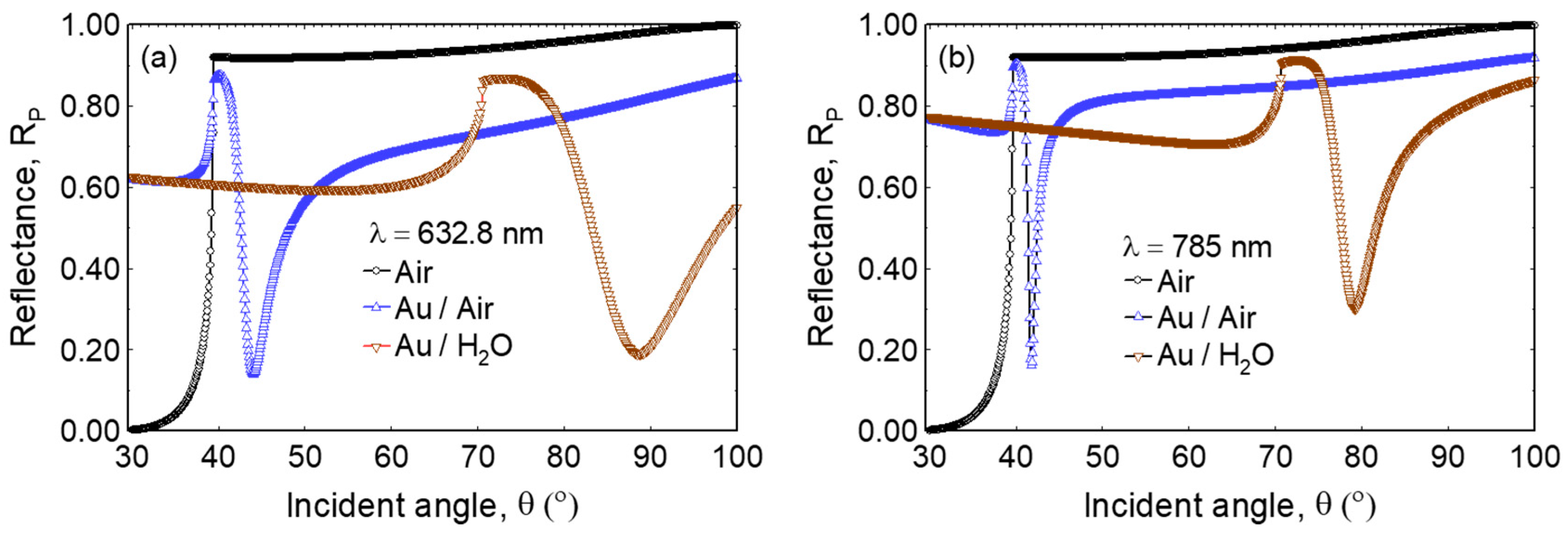
Figure 2 shows angle and wavelength dependent reflectivity profiles at (a) λ = 632.8 nm and (b) λ = 785 nm in the absence of Au, as compared to the Au SPR sensor configuration of Figure 1a. As shown by the black symbols, no SPR excitation is observed when light is incident into dielectric media, such as the glass/air interface, i.e., when there is no Au. Here the intensity of the reflected light approaches the critical angle, θc at which the incoming optical radiation is strongly reflected. The magnitude of Rp is zero near 30°, the Brewster angle. Due to the insertion loss, the magnitude of Rp is always below unity for all conditions.
Considering Au on the same substrate, above the critical angle the intensity for reflected p-polarized light significantly decreases with the increase in θ (shown in blue for air and red for water media). A dip is observed in the spectra around an incident angle of 43.8° (for air) and 88.4° (for water) at λ = 632.8 nm (Figure 2a) and 41.9° (for air) and 79.6° (for water) at λ = 785 nm (Figure 2b), suggesting that incident photons are being absorbed by the freely oscillating electrons of the metal on its surface, and this angle is λ dependent. This condition is regarded as the resonance condition at which surface plasmons on the sensor surface are excited. As shown by the red symbols, a shift in the resonance dip is observed when water replaces the air sensing medium. In each case, the reduced Rp is due to the establishment of SPR, and the shift of reflectance is due to the refractive index change between water and air.
In biosensing applications, depending on the sample type, the detection takes place only within a few nanometers to micrometer range from the sensor surface, where the molecular binding takes place. Note that the SPR evanescent waves have a skin depth of ~250 nm in water. Thus, the SPR angular shift depends on the thickness of the air or liquid sample being probed. In this work, we model the sample medium to be thick enough so that our metrics are not affected by finite layer thickness, allowing a direct comparison of sensor sensitivity between gas and liquid media.
3. SPR and Magneto-Optic SPR Fundamentals
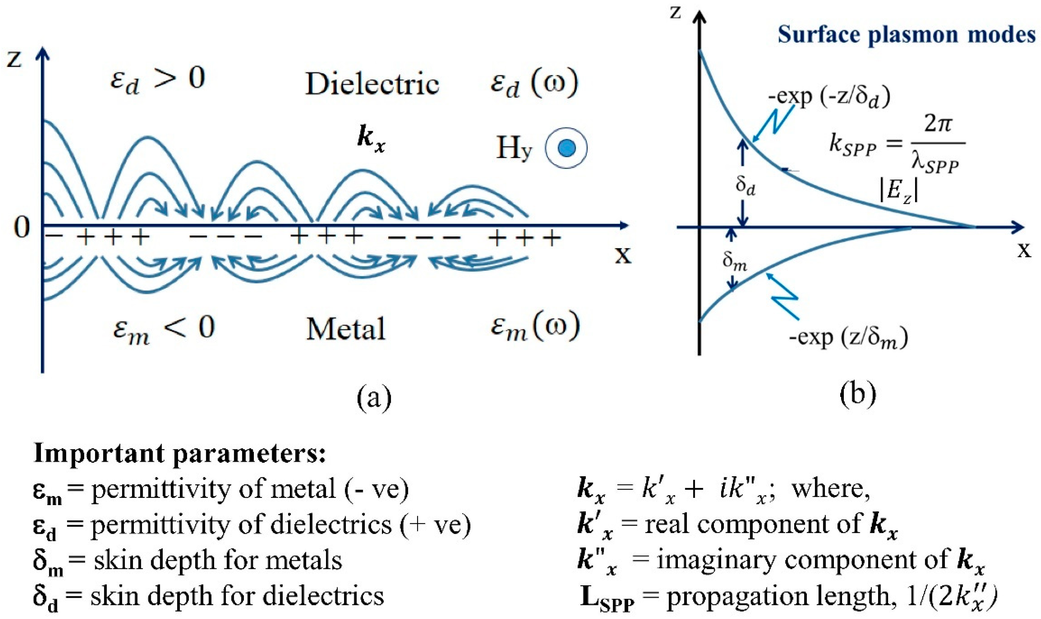
At the interface between the materials with negative and positive permittivities, which is the case for metal and dielectric layers, an incident electromagnetic (EM) radiation produces oscillations of the electron plasma on the metallic surface that in turn generate confined two-dimensional transverse EM waves at the interface. As shown in Figure 3, these waves, called surface plasmon polaritons (SPPs), are evanescent EM waves that decay exponentially in the direction perpendicular to the interface (z-axis) and practically vanish at both sides (±z-axes) of the interface.
The resonance for surface plasmons requires a light with a p-polarized component (the electric field, E, has the form Ep + Es, where Ep is in the plane of incidence (xz-plane, in Figure 1d and Es perpendicular to the plane of incidence) with a wave number k equal to that of SPPs, kSPP (dispersion equation)
where is the angular frequency, c is the speed of light, and and are the dielectric permittivity and magnetic permeability functions of the dielectric and metal materials, respectively.
The Kretschmann configuration allows for the light dispersion relation to intersect that of the SPP waves, where at resonance a sharp decrease in the reflected intensity takes place at an angle, θSPR, given as
where is the permittivity of the prism. Given that kSPP is very sensitive to the change of and of the materials, the fundamental detection principle of SPR sensors relies on the change of θSPR with respect to the permittivity (or the refractive index) of the dielectric material (usually gas or liquid containing an agent that drives the change of refractive index, such as bio-sample in water). Assuming that , , and are fixed, the reflectivity of the p-polarized light is a two-dimensional function of θ and , Rp (θ, ). As seen in Figure 2, at a minimum reflectivity, Rp we have . This implies that Rp is a function of and the ratio is required to be as large as possible for a high sensitive SPR sensor, which is challenging in practice. Given the shape of the Rp curve with respect to θ, the ratio that is clearly large is near θSPR. This ratio is what magneto-optic SPR (MO-SPR) sensors exploit to obtain high sensitivity. By applying a varying external H field, parallel to the metal-dielectric layer interface, but perpendicular to the incident plane, as shown in Figure 1d, the magneto-optic (MO) Kerr effect is induced and causes a modulation in kSPP and, therefore, a modulation in θSPR. The variation of Rp with and without H can be expressed as
By normalizing with respect to , we get,
In addition to eliminating the noise caused by fluctuations in the intensity of the incident radiation source, the ratio is more sensitive to the changes of than . This allows MO-SPR sensors to have a high resolution and improve the signal-to-noise-ratio (SNR) over conventional SPR sensors. This ratio is further normalized by the refractive index change and the sensitivity is expressed in 1/RIU units, where RIU stands for refractive index unit.
To directly compare the performance of SPR and MO-SPR sensors, we use sensitivity metrics that benchmark the performance of the sensors in terms of the measured quantities (reflected light intensity) in the conditions the sensors are operated, as follows.
For SPR sensors, sensitivity (%/RIU) is defined as [22]
where A and B denote the reflected intensity for two different media whose refractive indices vary by . The change in detected reflectivity is expressed in % by normalizing it to , which is the magnitude of reflected intensity at an incident angle , where its first derivative is maximized. This definition naturally relates to the conditions in which the sensor is operated, that is at an incidence angle where the sensor response is maximized. This definition also avoids obtaining diverging results, since the value for is never zero. Specifically, this avoids normalizing by the value of reflectivity at resonance, which is close to zero in optimal SPR sensors.
For the MO-SPR sensors, the sensitivity (%/RIU) is similarly defined as
where and ) are the change in reflectivity due to modulating H field for two different media A and B. The difference is normalized by where is the maximum for the first derivative . In addition, in this case, the values never diverge. We note that these two definitions are directly relatable, as they express the percentage change in the observable quantity (light intensity for SPR and H-field-modulated light intensity for MO-SPR) with respect to changes in refractive index () in the medium. In the following work, sensitivities calculated in air medium are obtained by comparing the calculated reflectivity curves for air and Helium gases, and for calculations in water medium the comparison is made between water and methanol liquids.
4. Results and Discussion
Reflectance characteristics of SPR and MO-SPR supporting platforms consisting of single noble and ferromagnetic layers and Cu/Co, Ag/Co, Au/Co bilayers have been compared in terms of sensitivity of the transducer.
4.1. SPR Response in Non-Magnetic Layer Configuration (Ag, Au, Cu)
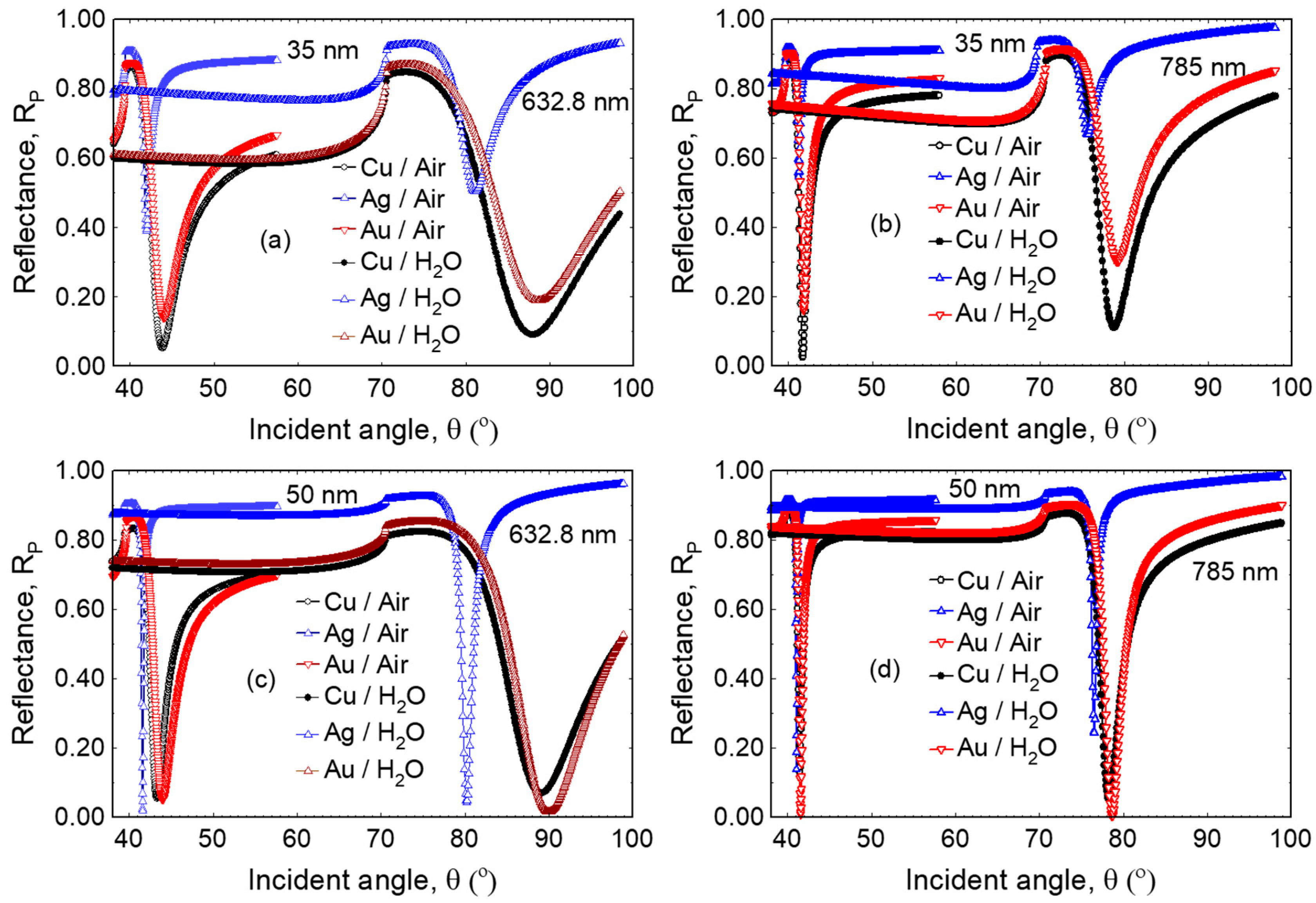
Figure 4 shows excitation angle dependent reflectivity profiles for three different transducers at 632.8 nm and 785 nm for air and water media, consisting of thin films of noble metals Cu, Ag, and Au, each with 35 nm (a,b) and 50 nm thickness (c,d). As shown in Figure 4a, Cu and Au showed a reflectivity minimum in gas medium of about 0.05 and 0.13, respectively when excited with an optical radiation of 632.8 nm, while Ag showed a minimum reflectivity of around 0.4. It is to be noted that the SPR for Ag was excited at lower angle of incidence of about 42° at this wavelength, whereas Au and Cu were excited at around 44°.
In the case of water as the probing medium, the minimum reflectivity is significantly shifted towards higher angles. SPR for Ag is again excited at a slightly lower angle of incidence around 80° where as Cu and Au were excited around 88°. The SPR curves are broader with respect to SPR curves in gas medium. On the other hand, at the excitation wavelength of 785 nm these same transducer configurations are excited at different angles of incidence and the peak width also narrowed significantly compared to the excitation wavelength of 632.8 nm, owing to lower optical losses at this wavelength (see, Figure 4b). Comparision of the sensitivities of these transducers are given in Table 2 and Table 3.
Figure 4c,d shows reflectivity profiles as function of angle of incidence for two different transducers consisting of thin films of noble metals Cu, Au and Ag, but with the metal thickness increased to 50 nm. The increased thickness leads to a reduction in reflectivity minima, and the peak width for both Ag and Au also narrowed significantly. The improvements in the SPR resonance as function of thickness and wavelength can both be linked to the evanescent wave penetration depth, which is given by . By increasing the film thickness, the SPR improved as the evanescent waves did not get perturbed by the finite thickness of the film. Similarly, at 785 nm, where the real part of the dielectric permittivity increases and the penetration depth decreases, the SPR evanescent waves experience less perturbations as compared to the case at 632.8 nm. Although Ag shows sharper SPR resonances it is not the best material for sensing applications as its surface can react and oxidize quickly. This can be mitigated with a thin dielectric protective layer.
4.2. SPR Response in Magnetic Layer Configuration (Fe, Co, Ni)
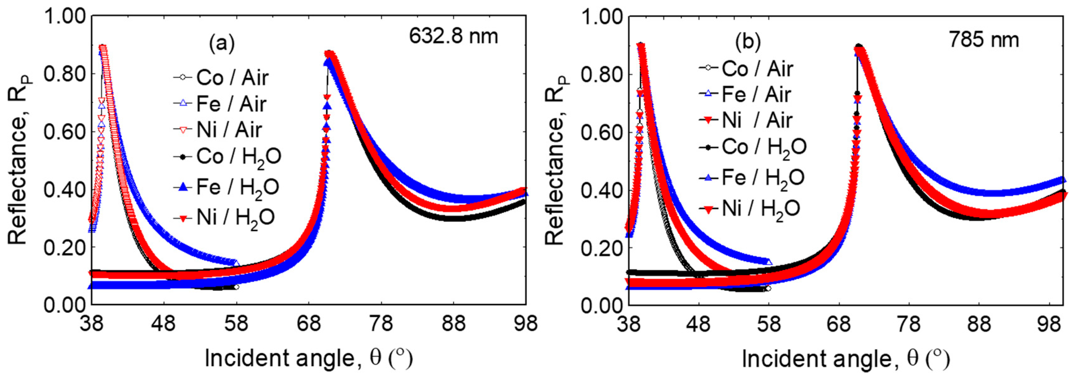
Figure 5 shows reflectivity profiles as function of angle of incidence for transducers consisting of single ferromagnetic layers. Fe, Co, and Ni layers support surface plasmons and they can be employed to control and tune magneto-optical effect. As shown in the figure, the reflectivity profile is very different from that of noble metals. Unlike Figure 4, no sharp reflectivity dip is observed in this case, but the SP response is instead very broad, with a minimum at or above 55° for air and 85° for water. On the contrary, these configurations showed sharp reflectivity peaks near an incident angle of 40° for air and 70° for water at the onset of total internal reflection. As shown in the figure, there is a dependence on the dielectric environment, particularly at the sharp onset of total internal reflection [22] that is not generally reported, which can also be used for sensing applications.
4.3. SPR Response in Non-Magnetic/Ferromagnetic Bilayer Configuration
As described above, several thin film configurations support excitation of surface plasmons leading to resonance. In all cases, the change of the dielectric medium is related to a change in angle of excitation corresponding to reflectivity minimum.
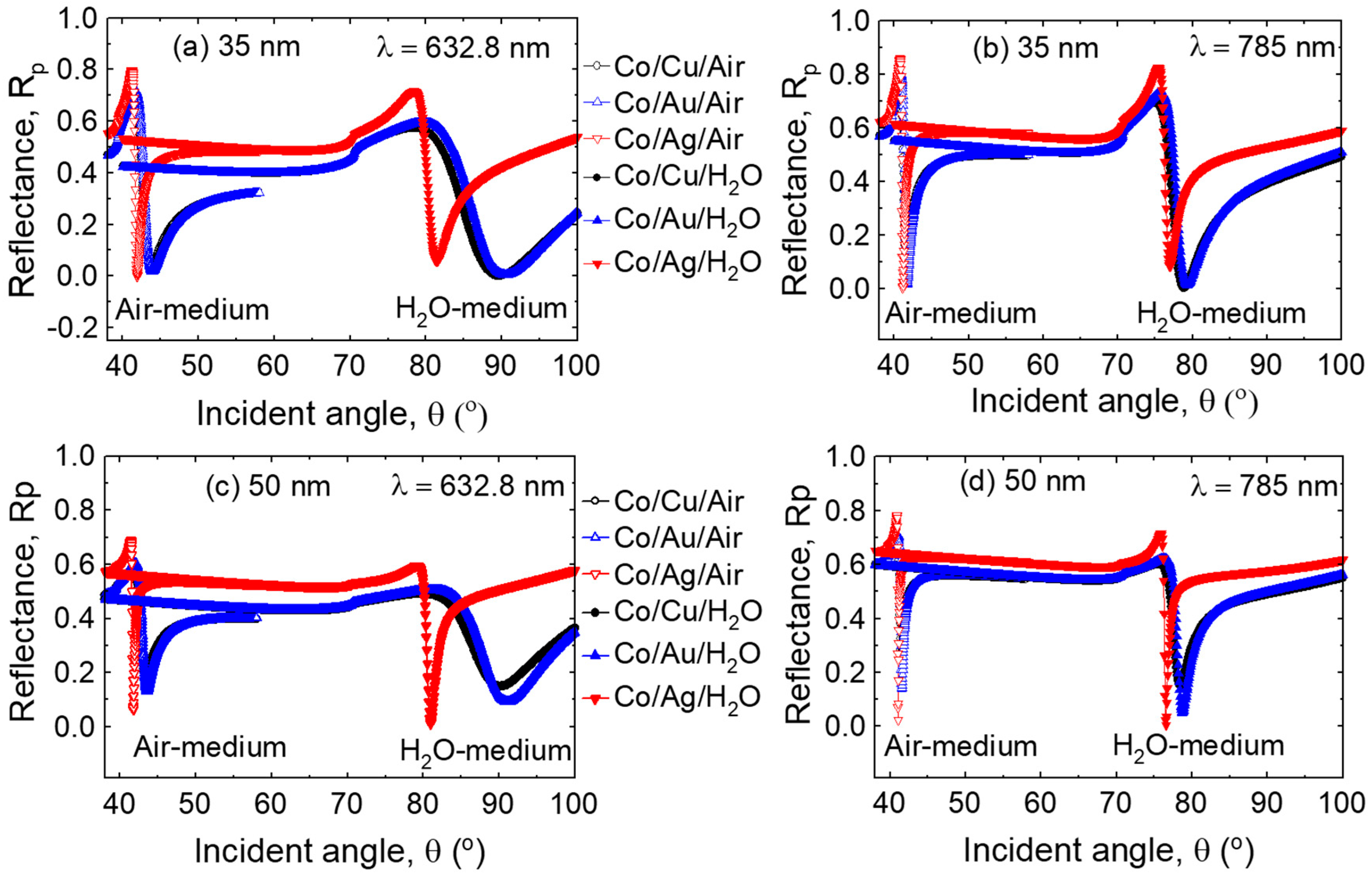
Figure 6a,b show reflectivity profiles of Co/Cu, Co/Ag, and Co/Au bilayers, consisting of a single ferromagnetic 8 nm Co layer on 35 or 50 nm of Cu or Au or Ag. All three transition metals support strong surface plasmons and the Co layer can be employed to control and tune the magneto-optical effect (see below). However, the sharpness and position of reflectivity minima are different with respect to those in Figure 4. These results suggest that spectroscopic and angular position of the SP resonance depend strongly on the bilayer configuration and optical properties of constituent layers. Not surprisingly, the addition of Co leads to optical absorption losses (lower overall reflectivity). The peak width for both Co/Cu, Co/Au, and Co/Ag bilayers still maintain a narrow characteristic, particularly at the excitation wavelength of 785 nm.
Figure 6c,d show reflectivity profiles of Co/Cu, Co/Au, and Co/Ag bilayers, consisting of a single ferromagnetic Co layer on Cu or Au or Ag with 50 nm thickness each. Note the resonance curves, especially for Ag. Despite the addition of Co layer, the resonances here are comparable to those obtained for similar noble metal thicknesses in Figure 4c,d, which is not what would be expected by adding a lossy material such as Co. Evidently, the addition of the Co layer is helpful in increasing the sharpness of the SPR by providing an overall thicker metal layer, reducing interface losses, without greately broadening the SPR resonance, as the Co layer is added away from the Au/air interface where the SP waves are mostly localized. While the angular interrogation method can still be employed for sensing as in typical SPR applications, these multilayers allow us to investigate reflecitivity changes due to a modulating magnetic field, ΔRp. We discuss this further in the next section.
4.4. MO-SPR in Non-Magnetic/Ferromagnetic Bilayer Configuration
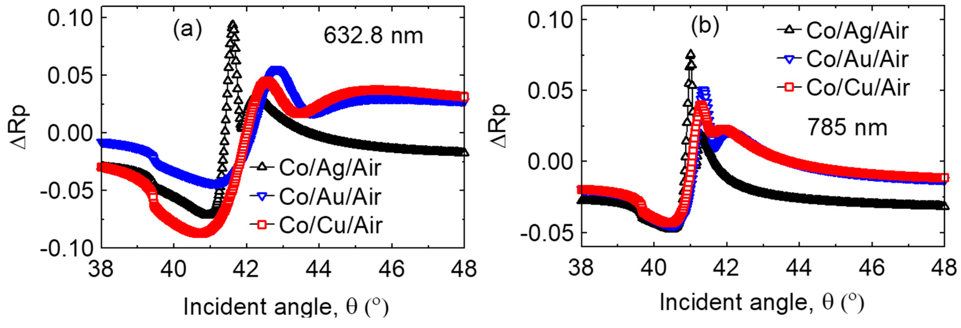
Figure 7 shows a comparison of magneto-optic Kerr effect produced by Co/Ag, Co/Au, and Co/Cu bilayers at the wavelength of 632.8 nm (a) and 785 nm (b) for air as the sensing medium. As shown, the bilayers displayed enhanced magneto-optic Kerr reflectivity at 632.8 nm in spite of the larger off-diagonal component of the dielectric tensor at 785 nm. Figure 8 shows a similar comparison for the water sensing medium. As in the air medium in Figure 7, these bilayers displayed enhanced magneto optic Kerr reflectivity at 632.8 nm. It is interesting to note also that the Kerr response is larger in water medium. These comparisons highlight the need to model the sensor performance at the wavelength and medium of interest. In order to compare the performance of these MO-SPR sensors to the SPR counterparts, we will present the sensitivities next.
4.5. Sensitivity Comparisons for SPR and MO-SPR Configurations
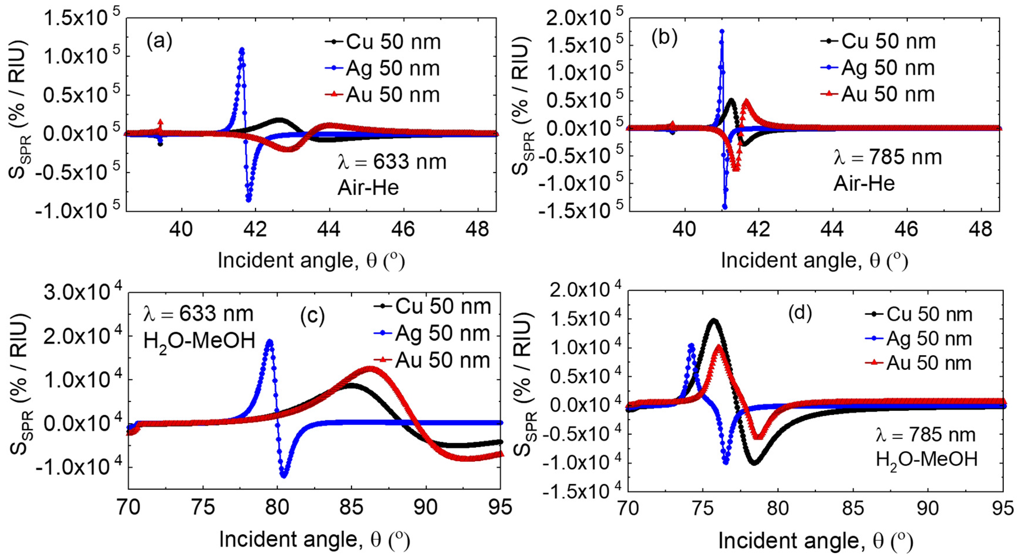
Figure 9 shows sensitivity comparisions between Cu, Ag, and Au based SPR sensors when the sensing medium undergoes refractive index transitions in the (a,b) air-based and (c,d) water-based media. Note that unlike the Kerr response alone, the sensitivity is improved at 785 nm when operating in air medium, but improved at 632.8 nm when operating in water medium. At either wavelength, operating in air medium has an improved response with respect to water medium, which is an important consideration for biosensing. Note that in comparing the sensitivities among SPR and MO-SPR structures, we have chosen 50 nm thick layers for the SPR structures, as these are found to have better performance, while the MO-SPR structures have only 35 nm thick noble metal layers.
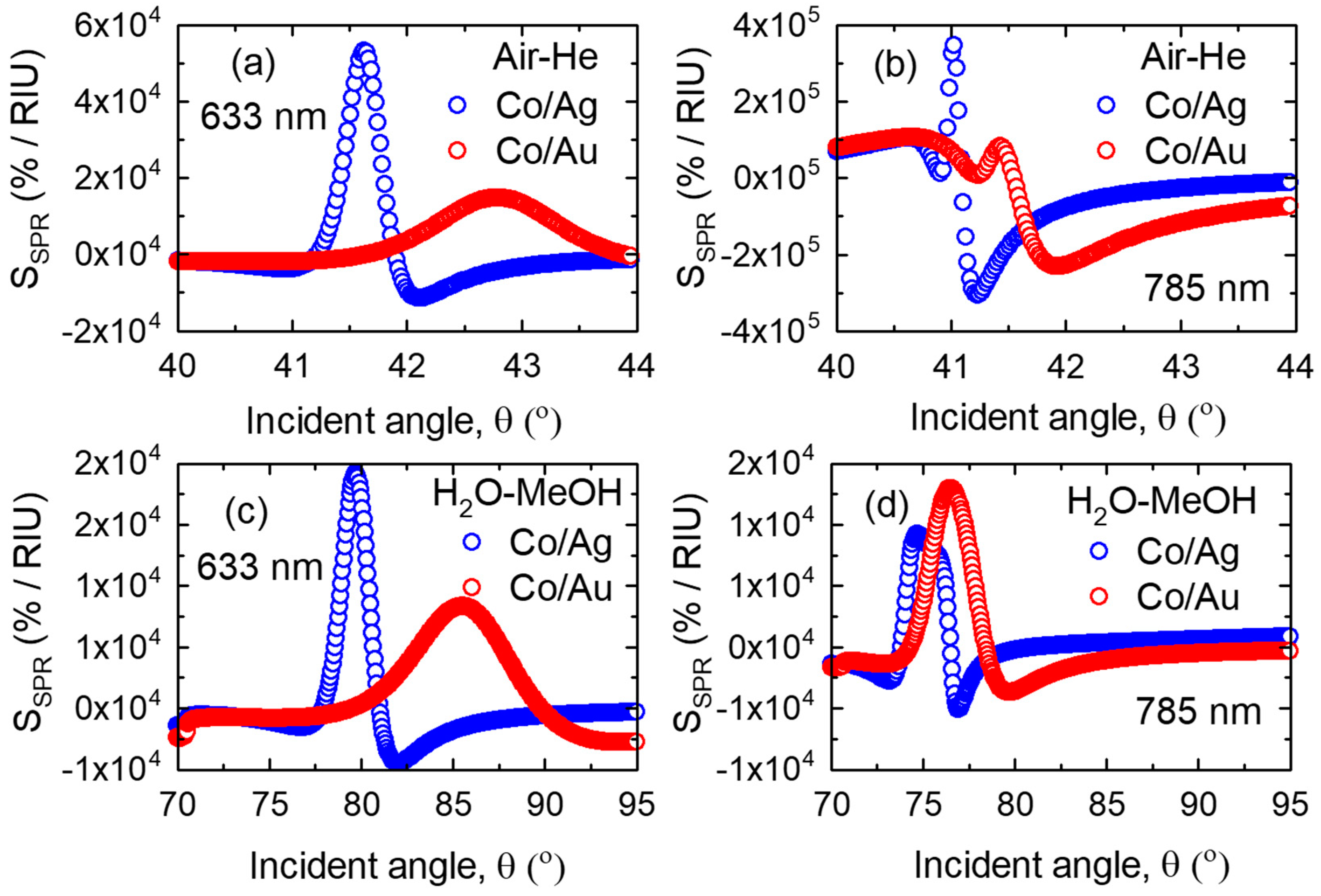
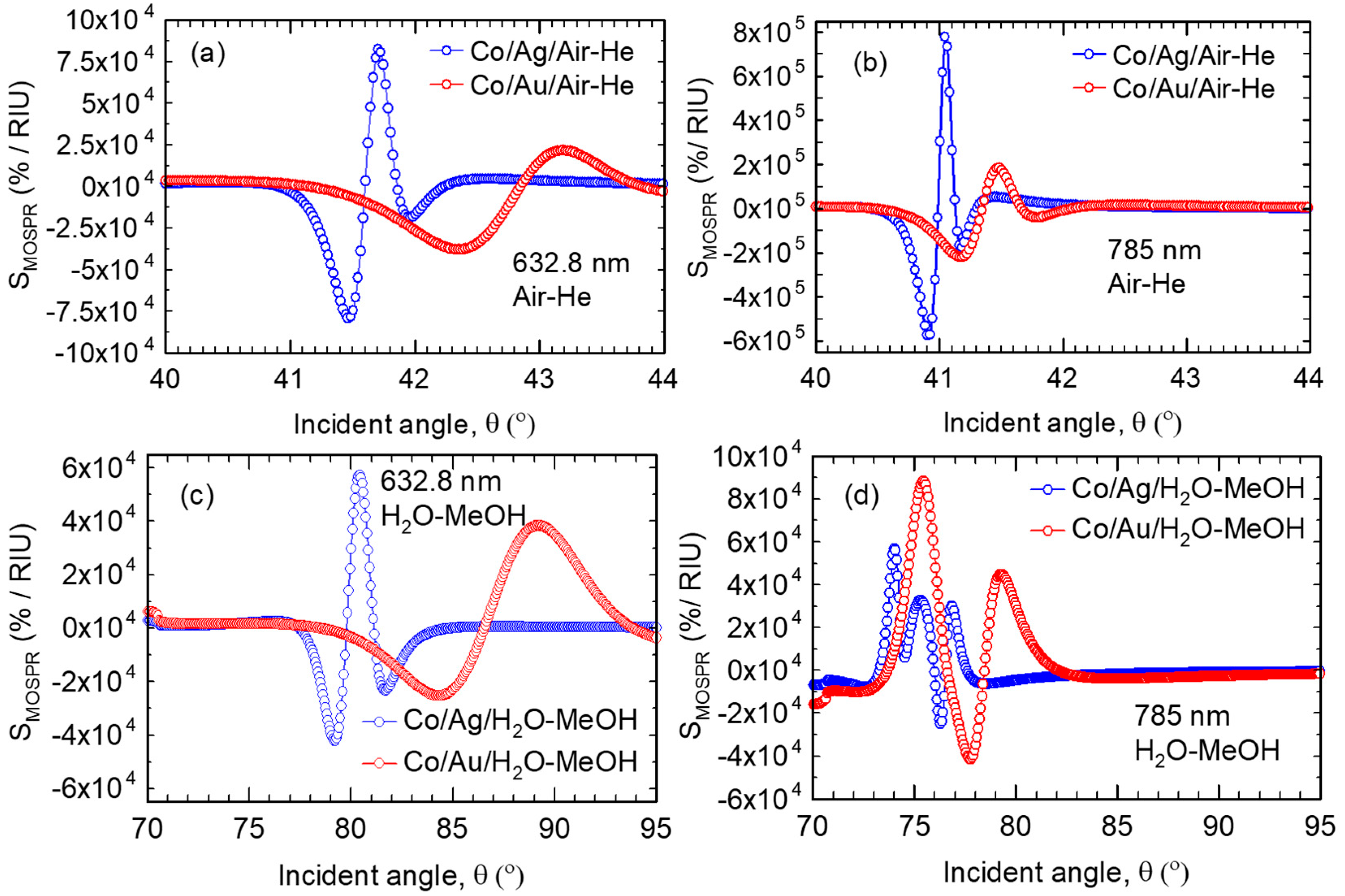
In Figure 10, the SPR sensitivities are compared for Co/Ag and Co/Au bilayers at two different wavelengths, whereas in Figure 11 the MO-SPR sensitivities are compared for the same bilayers. In practically all cases, introducing the Co deteriorated the SPR performance, but the MO-SPR response showed an overall much higher sensitivity as compared to any of the SPR configurations, highlighting the usefulness of MO effect in improving sensors’ sensitivity.
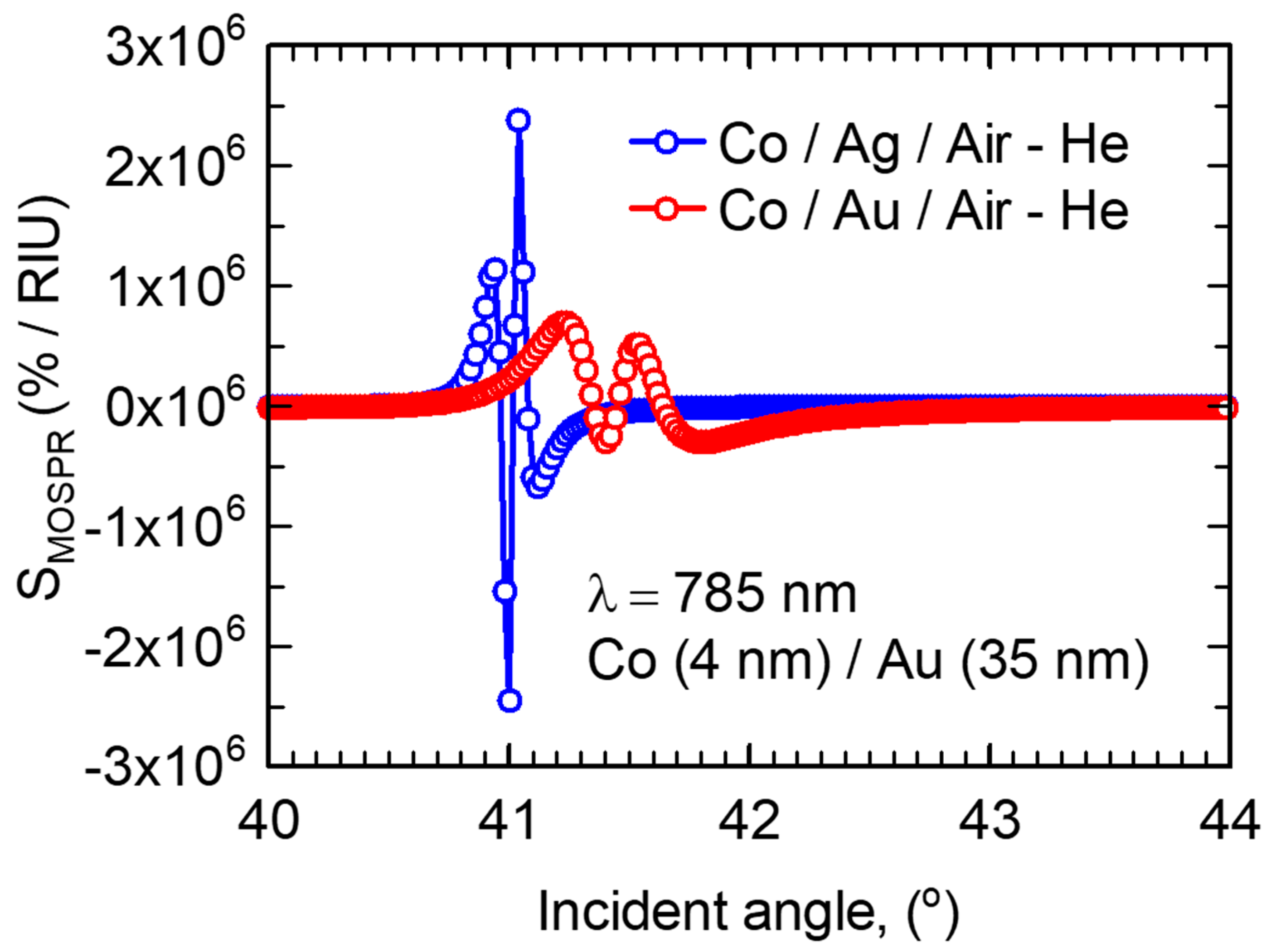
For air medium, the sensitivity of the Co/Ag MO-SPR sensor at 785 nm in Figure 11b is improved by a factor of 4.6× as compared to the best SPR sensor (Ag at 785 nm), and a similar improvement is seen for the Co/Au MO-SPR sensor with respect to Au SPR sensors. For water medium, the sensitivity of the MO-SPR sensors show similar improvements compared to SPR mode. Given that Co is a lossy material, in Figure 12 we show how the MO-SPR performance is further improved by reducing the layer thickness to 4 nm. We note that the optimal MO-SPR sensor in Figure 12 is over 13× more sensitive than the best SPR single-layer Ag sensor in this work, and over 30× more sensitive than Au SPR sensors that are typical of state-of-the-art SPR sensors in air (Figure 9b). Considering that the peak sensitivity found here for the optimal MO-SPR sensor of 2.5 × 10⁶ %/RIU is given by a relative signal strength of 2.5 × 10⁴ RIU−1, we can estimate the detection limit D based on the reported detection noise of σ = 5 × 10⁻⁴ for this type of measurements [12]. We obtain D = 2 × 10⁻⁸ RIU, an improvement of over an order of magnitude with respect to currently available SPR sensors, which have D~10−4 to 10−7 RIU [12,23]. We note that this detection limit is a more than a three-times improvement over the reported theoretical response of MO-SPR sensors coupled to a photonic crystal [12]. The actual detection limit may differ from the estimate above, as the detection noise is dependent on the detection scheme.
The marked difference in the sensitivities obtained for air versus water media highlights that this class of sensors require layer thickness optimization and performance evaluation according to the application envisioned. For example, for gas sensing, as seen in Table 2, a MO-SPR sensor structure based on a Ag layer would be preferred, whereas, as seen in Table 3, for water-based sensing, a MO-SPR sensor structure based on a Au layer would yield higher sensitivity. In general, we find that for a given sensor structure, the sensitivity is a non-linear function of the operating wavelength, sensing medium refractive index, and refractive index change being sensed. Typically, operating at longer wavelengths, in low refractive index media and sensing small deviations in refractive index yields higher sensitivities. The trend relating to operating wavelength simply follows the optical losses of the metallic layers. The dependence on sensing medium reflects the smaller resonance linewidths achieved at lower incidence angles, yielding larger response slopes (see for example Figure 2). Small resonance linewidths also lead to the trend of reduced sensitivities for larger changes in sensed refractive index, since the shifts of the response curves as function of refractive index lead to a saturating behavior of the reflectivity.
5. Conclusions
We studied a series of noble and ferromagnetic metals, and Co/Ag and Co/Au sensor configurations and investigated the SPR and MO-SPR characteristics. We defined sensitivity metrics that can be applied consistently for comparisons between SPR and MO-SPR sensors. The Au SPR sensing configurations showed refractive index detection limits of 7 × 10⁻⁷ RIU, comparable with commercial sensors. An improvement in reflectivity minimum is seen with changing SPR configuration by adding a ferromagnetic layer below the noble metal, but this is attributed solely to lower losses associated with increasing the film thickness, similarly to what can be obtained by simply increasing the noble metal thickness alone. Using MO-SPR detection in bilayer configurations, where the slope of the responses produced by an external modulated magnetic field is sharper, the sensitivity of the sensor is amplified significantly, with a detection limit of 2 × 10⁻⁸ RIU for Ag/Co bilayer, an improvement of over 30× compared to typical SPR sensors and 3× over optimized MO-SPR sensors coupled to a photonic crystal. Experimental work on the sensing performance of the single layer and bilayer structures in the SPR and MO-SPR transducing configurations is currently ongoing.
Author Contributions
C.R. conceived and designed the experiment, and performed simulations. C.R. and S.P. analyzed the data. C.R. and S.P. wrote the paper. All authors read and approved the manuscript.
Acknowledgments
The authors acknowledge York University, GEM Systems Inc., CMC Microsystems, and MITACS Canada for providing financial support for this work.
Conflicts of Interest
The authors declare no conflict of interest.
References
- Maier, S.A. Plasmonics: Fundamentals and Applications; Springer Science & Business Media: Berlin/Heidelberg, Germany, 2007. [Google Scholar]
- Nagata, K.; Handa, H. Real-Time Analysis of Biomolecular Interactions (Applications of Biacore); Springer: New York, NY, USA, 2000. [Google Scholar]
- Sharma, A.; Tomar, M.; Gupta, V. Room temperature trace level detection of NO2 gas using SnO2 modified carbon nanotubes based sensor. J. Mater. Chem. 2012, 22, 23608–23616. [Google Scholar] [CrossRef]
- Huang, Q.; Zeng, D.; Li, H.; Xie, C. Room temperature formaldehyde sensors with enhanced performance, fast response and recovery based on zinc oxide quantum dots/graphene nanocomposites. Nanoscale 2012, 4, 5651–5658. [Google Scholar] [CrossRef] [PubMed]
- Kretschmann, E. The angular dependence and the polarisation of light emitted by surface plasmons on metals due to roughness. Opt. Commun. 1972, 5, 331–336. [Google Scholar] [CrossRef]
- Otto, A. Excitation of nonradiative surface plasma waves in silver by the method of frustrated total reflection. Z. Phys. A Hadrons Nucl. 1968, 216, 398–410. [Google Scholar] [CrossRef]
- Dakss, M.; Kuhn, L.; Heidrich, P.; Scott, B. Grating coupler for efficient excitation of optical guided waves in thin films. Appl. Phys. Lett. 1970, 16, 523–525. [Google Scholar] [CrossRef]
- Rizal, C.; Niraula, B.; Lee, H. Bio-Magnetoplasmonics, Emerging Biomedical Technologies and Beyond. J. Nanomed. Res. 2016, 3, 00059. [Google Scholar] [CrossRef]
- Bonanni, V.; Bonetti, S.; Pakizeh, T.; Pirzadeh, Z.; Chen, J.; Noguis, J.; Vavassori, P.; Hillenbrand, R.; Ãkerman, J.; Dmitriev, A. Designer magnetoplasmonics with nickel nanoferromagnets. Nano Lett. 2011, 11, 5333–5338. [Google Scholar] [CrossRef] [PubMed]
- Brolo, A.G. Plasmonics for future biosensors. Nat. Photonics 2012, 6, 709–713. [Google Scholar] [CrossRef]
- Armelles, G.; Cebollada, A.; Garcia-Martan, A.; Gonzalez, M.U. Magnetoplasmonics: Combining Magnetic and Plasmonic Functionalities. Adv. Opt. Mater. 2013, 1, 2–21. [Google Scholar] [CrossRef]
- Ignatyeva, D.O.; Knyazev, G.A.; Kapralov, P.O.; Dietler, G.; Sekatskii, S.K.; Belotelov, V.I. Magneto-optical plasmonic heterostructure with ultranarrow resonance for sensing applications. Sci. Rep. 2016, 6, 28077. [Google Scholar] [CrossRef] [PubMed]
- Jain, P.K.; Xiao, Y.; Walsworth, R.; Cohen, A.E. Surface plasmon resonance enhanced magneto-optics (SuPREMO): Faraday rotation enhancement in gold-coated iron oxide nanocrystals. Nano Lett. 2009, 9, 1644–1650. [Google Scholar] [CrossRef] [PubMed]
- Lodewijks, K.; Maccaferri, N.; Pakizeh, T.; Dumas, R.K.; Zubritskaya, I.; Ãkerman, J.; Vavassori, P.; Dmitriev, A. Magnetoplasmonic design rules for active magneto-optics. Nano Lett. 2014, 14, 7207–7214. [Google Scholar] [CrossRef] [PubMed]
- Manera, M.G.; Ferreiro-Vila, E.A.; Garcia-Martin, J.M.; Garcia-Martin, A.; Rella, R. Enhanced antibody recognition with a magneto-optic surface plasmon resonance (MO-SPR) sensor. Biosens. Bioelectron. 2014, 58, 114–120. [Google Scholar] [CrossRef] [PubMed] [Green Version]
- Newman, D.M.; Wears, M.L.; Matelon, R.J.; Hooper, I.R. Magneto-optic behaviour in the presence of surface plasmons. J. Phys. Condens. Matter 2008, 20, 345230. [Google Scholar] [CrossRef] [Green Version]
- Papaioannou, E.T.; Karoutsos, V.; Angelakeris, M.; Valassiades, O.; Fumagalli, P.; Flevaris, N.K.; Poulopoulos, P. Magnetic, magneto-optic and magnetotransport properties of nanocrystalline Co/Au multilayers with ultrathin Au interlayers. J. Nanosci. Nanotechnol. 2008, 8, 4323–4327. [Google Scholar] [CrossRef] [PubMed]
- Schubert, M.; Tiwald, T.E.; Woollam, J.A. Explicit solutions for the optical properties of arbitrary magneto-optic materials in generalized ellipsometry. Appl. Opt. 1999, 38, 177–187. [Google Scholar] [CrossRef] [PubMed]
- Sepúlveda, B.; Calle, A.; Lechuga, L.M.; Armelles, G. Highly sensitive detection of biomolecules with the magneto-optic surface-plasmon-resonance sensor. Opt. Lett. 2006, 31, 1085–1087. [Google Scholar] [CrossRef] [PubMed]
- Zvezdin, A.K.; Kotov, V.A. Modern Magnetooptics and Magnetooptical Materials; CRC Press: Boca Raton, FL, USA, 1997. [Google Scholar]
- Regatos, D.; Sepúlveda, B.; Fariña, D.; Carrascosa, L.G.; Lechuga, L.M. Suitable combination of noble/ferromagnetic metal multilayers for enhanced magneto-plasmonic biosensing. Opt. Express 2011, 19, 8336–8346. [Google Scholar] [CrossRef] [PubMed]
- Rizal, C.; Pisana, S.; Hrvoic, I.; Fullerton, E. Microstructure and magneto-optical surface plasmon resonance of Co/Au multilayers. J. Phys. Commun. 2018, 2, 055010. [Google Scholar] [CrossRef] [Green Version]
- Piliarik, M.; Homola, J. Surface plasmon resonance (SPR) sensors: Approaching their limits? Opt. Express 2009, 17, 16505–16517. [Google Scholar] [CrossRef] [PubMed]
- Wang, T.-J.; Lee, K.-H.; Chen, T.-T. Sensitivity enhancement of magneto-optic surface plasmon resonance sensors with noble/ferromagnetic metal heterostructure. Laser Phys. 2014, 24, 036001. [Google Scholar] [CrossRef]
- D’Amico, A.; Di Natale, C. A contribution on some basic definitions of sensors properties. IEEE Sens. J. 2001, 1, 183–190. [Google Scholar] [CrossRef]
- Schasfoort, R.B.M.; Tudos, A.J. Handbook of Surface Plasmon Resonance; Royal Society of Chemistry: London, UK, 2008. [Google Scholar]
- Maksymov, I.S. Magneto-plasmonics and resonant interaction of light with dynamic magnetisation in metallic and all-magneto-dielectric nanostructures. Nanomaterials 2015, 5, 577–613. [Google Scholar] [CrossRef] [PubMed]
- Temnov, V.V. Ultrafast acousto-magneto-plasmonics. Nat. Photonics 2012, 6, 728–736. [Google Scholar] [CrossRef] [Green Version]
- Vila, E.-F.; Bendana Sueiro, X.M.; Gonzalez-Diaz, J.B.; Garcia-Martin, A.; Garcia-Martin, J.M.; Cebollada Navarro, A.; Armelles Reig, G.; Meneses Rodriguez, D.; Sandoval, E.M. Surface plasmon resonance effects in the magneto-optical activity of Ag/Co/Ag trilayers. IEEE Trans. Magn. 2008, 44, 3303–3306. [Google Scholar] [CrossRef] [Green Version]
- Rizal, C.; Fullerton, E. Perpendicular magnetic anisotropy and microstructure properties of nanoscale Co/Au multilayers. J. Phys. D Appl. Phys. 2017, 50, 355002. [Google Scholar] [CrossRef]
- González-Díaz, J.; Sepúlveda, B.; García-Martín, A.; Armelles, G. Cobalt dependence of the magneto-optical response in magnetoplasmonic nanodisks. Appl. Phys. Lett. 2010, 97, 043114. [Google Scholar] [CrossRef] [Green Version]
- Pellegrini, G.; Mattei, G. High-performance magneto-optic surface plasmon resonance sensor design: An optimization approach. Plasmonics 2014, 9, 1457–1462. [Google Scholar] [CrossRef]
- Robertson, W.M.; Fullerton, E. Reexamination of the surface-plasma-wave technique for determining the dielectric constant and thickness of metal films. J. Opt. Soc. Am. B 1989, 6, 1584–1589. [Google Scholar] [CrossRef]
Figure 1.
(a–d) Four different sensor configurations consisting of the following: substrate (BK-7 glass), buffer layer (Ta), and sensor layers tx in (a), where tx denotes thickness of noble metals Au, Ag, Cu and ty in (b) denotes thickness of ferromagnetic Fe, Co, Ni. The probed sample medium in (a–c) is a gas, and tF in (d) denotes the thickness of the probed fluid. Notations in (d): L1, L2 denote lenses, and and denote incident and reflected angles of the optical radiation, respectively. and vectors denote the p-polarized electric field of the light radiation and externally applied magnetic field in the transverse direction, respectively.

Figure 2.
Reflectance, Rp vs. incident angle, θ at (a) λ = 632.8 nm and (b) λ = 785 nm in the absence of Au, and for the Au SPR sensors with air and water as sample media. The Au layer thickness is 35 nm. The resonance peak minima shifted towards higher angles indicating that the resonance peak is highly sensitive to change in refractive index of the medium at the metal-dielectric interface.

Figure 3.
SPR Waves (a) SPR propagating along the interface between metal and dielectric material and (b) Field magnitude across the interface and normal to propagation direction. Hy denotes the direction of applied magnetic field acting along the y-axis (parallel to metal-dielectric interface) for the magneto-optic SPR effect.

Figure 4.
(a,b) Reflectivity profiles as function of angle of incidence for Cu, Au, and Ag metallic films and at excitation wavelength of (a,c) λ = 632.8 nm and (b,d) λ = 785 nm. The thickness of the metal layer in (a,b) is 35 nm, and in (c,d) is 50 nm.
Figure 4.
(a,b) Reflectivity profiles as function of angle of incidence for Cu, Au, and Ag metallic films and at excitation wavelength of (a,c) λ = 632.8 nm and (b,d) λ = 785 nm. The thickness of the metal layer in (a,b) is 35 nm, and in (c,d) is 50 nm.

Figure 5.
(a,b) Reflectivity profiles as function of angle of incidence for ferromagnetic metals (Fe, Co, Ni) in air and water media at (a) λ = 632.8 nm and (b) λ = 785 nm. In all cases, the thickness of each layer is kept at 8 nm.
Figure 5.
(a,b) Reflectivity profiles as function of angle of incidence for ferromagnetic metals (Fe, Co, Ni) in air and water media at (a) λ = 632.8 nm and (b) λ = 785 nm. In all cases, the thickness of each layer is kept at 8 nm.

Figure 6.
Reflectivity profiles as function of angle of incidence for ferromagnetic multilayers with tCo = 8 nm and tCu,Au,Ag = 35 nm (a,b) and tCu,Au,Ag = 50 nm (c,d) with air and water media excited at (a,c) λ = 632.8 nm and (b,d) λ = 785 nm.
Figure 6.
Reflectivity profiles as function of angle of incidence for ferromagnetic multilayers with tCo = 8 nm and tCu,Au,Ag = 35 nm (a,b) and tCu,Au,Ag = 50 nm (c,d) with air and water media excited at (a,c) λ = 632.8 nm and (b,d) λ = 785 nm.

Figure 7.
ΔRp calculated for Co/Ag, Co/Au, and Co/Cu bilayers at (a) λ = 632.8 nm and (b) λ = 785 nm in air medium. Thickness of Co is kept at 8 nm and tAg, tAu, and tCu were each 35 nm. ΔRp is caculated as Rp(H) − Rp(0).
Figure 7.
ΔRp calculated for Co/Ag, Co/Au, and Co/Cu bilayers at (a) λ = 632.8 nm and (b) λ = 785 nm in air medium. Thickness of Co is kept at 8 nm and tAg, tAu, and tCu were each 35 nm. ΔRp is caculated as Rp(H) − Rp(0).

Figure 8.
ΔRp calculated for Co/Ag, Co/Au, and Co/Cu bilayers at (a) λ = 632.8 nm and (b) λ = 785 nm in water medium. Thickness of Co is kept at 8 nm and tAg, tAu and tCu were each 35 nm. ΔRp is calculated as Rp(H) − Rp(0).
Figure 8.
ΔRp calculated for Co/Ag, Co/Au, and Co/Cu bilayers at (a) λ = 632.8 nm and (b) λ = 785 nm in water medium. Thickness of Co is kept at 8 nm and tAg, tAu and tCu were each 35 nm. ΔRp is calculated as Rp(H) − Rp(0).
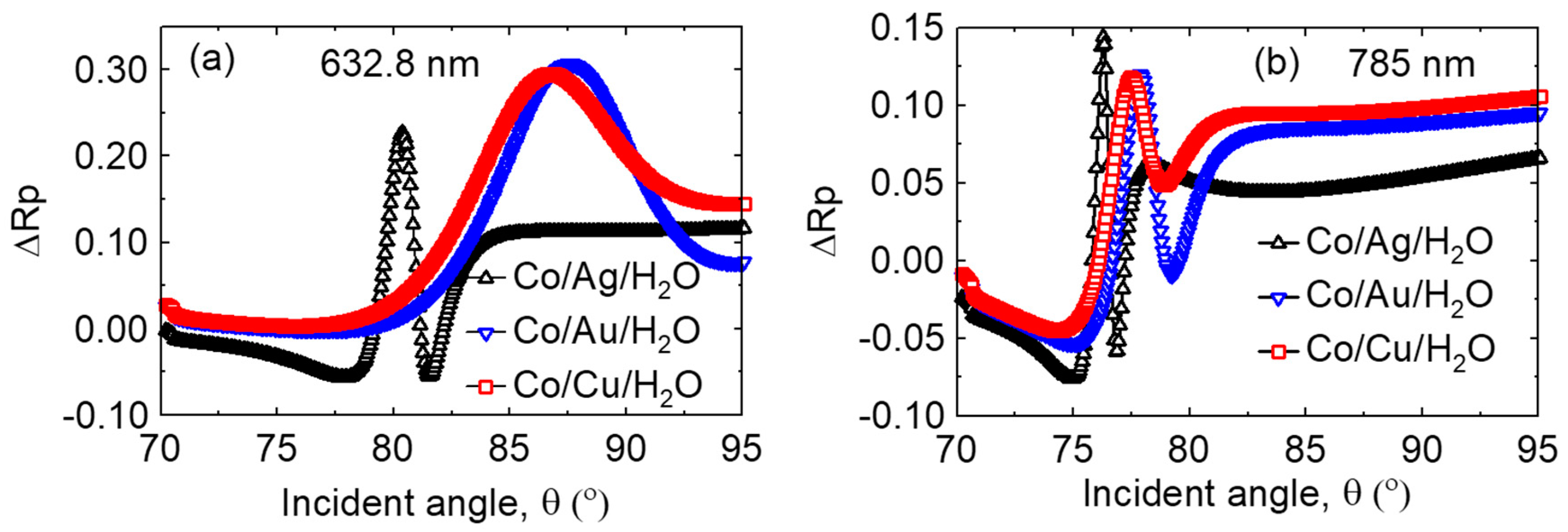
Figure 9.
The SPR sensitivity with (a,b) air–He transitions and (c,d) water–methanol transitions in the sensing medium at (a,c) λ = 632.8 nm and (b,d) 785 nm.
Figure 9.
The SPR sensitivity with (a,b) air–He transitions and (c,d) water–methanol transitions in the sensing medium at (a,c) λ = 632.8 nm and (b,d) 785 nm.

Figure 10.
The SPR sensitivity comparision for Co/Ag and Co/Au bilayers at two different wavelengths. (a,b) air–He and (c,d) water–methanol media. The thickness of Co is kept at 8 nm and Ag and Au are 35 nm each.
Figure 10.
The SPR sensitivity comparision for Co/Ag and Co/Au bilayers at two different wavelengths. (a,b) air–He and (c,d) water–methanol media. The thickness of Co is kept at 8 nm and Ag and Au are 35 nm each.

Figure 11.
The MO-SPR sensitivity comparision for Co/Ag and Co/Au multilayers at two different wavelengths. (a,b) air–He and (c,d) water–methanol media. The thickness of Co is kept at 8 nm and Ag and Au 35 nm each.
Figure 11.
The MO-SPR sensitivity comparision for Co/Ag and Co/Au multilayers at two different wavelengths. (a,b) air–He and (c,d) water–methanol media. The thickness of Co is kept at 8 nm and Ag and Au 35 nm each.

Figure 12.
The MO-SPR sensitivity comparision for Co/Ag and Co/Au multilayers at 785 nm in air medium. The thickness of the Co is reduced to 4 nm, whereas Ag and Au are kept at 35 nm each.
Figure 12.
The MO-SPR sensitivity comparision for Co/Ag and Co/Au multilayers at 785 nm in air medium. The thickness of the Co is reduced to 4 nm, whereas Ag and Au are kept at 35 nm each.


Table 1.
Optical and geometrical parameters of sensor configurations at λ = 632.8 nm and 785 nm. εmo denotes the magneto-optical component of dielectric function. εmo for Co was obtained from [31].
Table 1.
Optical and geometrical parameters of sensor configurations at λ = 632.8 nm and 785 nm. εmo denotes the magneto-optical component of dielectric function. εmo for Co was obtained from [31].
| Material | Thickness t (nm) | Permittivity, ε; εmo at λ = 632.8 nm | Permittivity, ε; εmo at λ = 785 nm |
|---|---|---|---|
| Substrate/BK-7 | 1.3 mm | 2.2940 | 2.2813 |
| BK-7 Prism | - | 2.2940 | 2.2813 |
| Index match Liquid | - | 2.2940 | 2.2813 |
| Au | 35/50 | −11.127 + j1.3268 | −22.855 + j1.4245 |
| Ag | 35/50 | −18.228 + j0.48198 | −29.789 + j0.37611 |
| Cu | 35/50 | −11.560 + j1.8393 | −23.893 + j2.4365 |
| Co | 4/8 | −12.475 + j18.451; −0.65 + j0.0005 | −16.493 + j23.377; −0.85 + j0.0006 |
| Fe | 8 | −1.0366 + j17.771 | −2.0612 + j21.601 |
| Ni | 8 | −12.944 + j16.363 | −6.5092 + j24.811 |
| Ta | 2 | −31.101 + 12.005 | −50.104 + j14.240 |
| He | - | 1.0000698 | 1.0000696 |
| Air | - | 1.000553 | 1.0005502 |
| Methanol | - | 1.759 | 1.7296 |
| Water | - | 1.7734 | 1.7678 |
Table 2.
Comparison of SPR and MO-SPR sensitivity (air–He media).
| Material | SPR Sensitivity (632.8 nm) | MO-SPR Sensitivity (632.8 nm) | SPR Sensitivity (785 nm) | MOSPR Sensitivity (785 nm) |
|---|---|---|---|---|
| Cu(50) | 2.0 × 10⁴ | - | 5.0 × 10⁴ | - |
| Ag(50) | 1.1 × 10⁵ | - | 1.8 × 10⁵ | - |
| Au(50) | 2.5 × 10⁴ | - | 7.5 × 10⁴ | - |
| Co(8)/Ag(35) | 5.2 × 10⁴ | 8.0 × 10⁴ | 3.3 × 10⁵ | 8.0 × 10⁵ |
| Co(8)/Au(35) | 1.6 × 10⁴ | 4.0 × 10⁴ | 2.1 × 10⁵ | 2.2 × 10⁵ |
| Co(4)/Ag(35) | - | - | - | 2.5 × 10⁶ |
| Co(4)/Au(35) | - | - | - | 5.7 × 10⁵ |
Table 3.
Comparison of SPR and MO-SPR sensitivity (water–methanol media).
| Material | SPR Sensitivity (632.8 nm) | MOSPR Sensitivty (632.8 nm) | SPR Sensitivity (785 nm) | MOSPR Sensitivty (785 nm) |
|---|---|---|---|---|
| Cu(50) | 7.0 × 10³ | - | 1.5 × 10⁴ | - |
| Ag(50) | 1.9 × 10⁴ | - | 1.1 × 10⁴ | - |
| Au(50) | 1.3 × 10⁴ | - | 1.1 × 10⁴ | - |
| Co(8)/Ag(35) | 1.9 × 10⁴ | 5.6 × 10⁴ | 9.0 × 10³ | 5.7 × 10⁴ |
| Co(8)/Au(35) | 8.0 × 10³ | 3.7 × 10⁴ | 1.3 × 10⁴ | 9.0 × 10⁴ |
© 2018 by the authors. Licensee MDPI, Basel, Switzerland. This article is an open access article distributed under the terms and conditions of the Creative Commons Attribution (CC BY) license (http://creativecommons.org/licenses/by/4.0/).
Share and Cite
MDPI and ACS Style
Rizal, C.; Pisana, S.; Hrvoic, I. Improved Magneto-Optic Surface Plasmon Resonance Biosensors. Photonics 2018, 5, 15. https://doi.org/10.3390/photonics5030015
AMA Style
Rizal C, Pisana S, Hrvoic I. Improved Magneto-Optic Surface Plasmon Resonance Biosensors. Photonics. 2018; 5(3):15. https://doi.org/10.3390/photonics5030015
Chicago/Turabian StyleRizal, Conrad, Simone Pisana, and Ivan Hrvoic. 2018. "Improved Magneto-Optic Surface Plasmon Resonance Biosensors" Photonics 5, no. 3: 15. https://doi.org/10.3390/photonics5030015
Note that from the first issue of 2016, this journal uses article numbers instead of page numbers. See further details here.