1. Introduction
Warehouse scale data centers (DCs) host several hundreds of thousands of servers and other equipment, spreading across thousands of racks that are interconnected by an underlying intra-data center network (intra-DCN) architecture. Such architectures should be highly scalable, upgradable, energy efficient, and extremely cost-effective [
1]. Nowadays, most intra-DCNs are based on scale-up hierarchical designs (e.g., fat-tree [
2] and butterfly [
3]) which suffer from oversubscription, lack of fault tolerance, expensive layer-2/3 switches/routers, weak re-configurability, and poor scalability when traffic increases. New architectures (e.g., based on modular designs) have been recently proposed addressing these issues [
4]. However, the proposed solutions impose other challenges that demand low-cost/low-power dynamic re-configurability and seamless scalability [
5].
Optical fibers and fiber-pigtailed transceivers are the key elements in constructing traditional DCNs. Millions of meters of fiber are required, forming an extremely complex cabling system that is difficult to manage [
6], with the choice of cabling architecture greatly influencing the throughput, scalability, and energy efficiency management of a DC [
6,
7]. Although the cabling problem is still underestimated, when the scaling and cost of large infrastructures is under consideration, recent studies have started paying attention to its side effects. For instance, it was shown that the mass of long cables between the switches causes great difficulties in system maintenance [
5]. When the network connection changes or line failure occurs, the system upgrading becomes extremely complicated. IBM also reported that the dense cabling will affect the heat dissipation due to the fact that airflow is obstructed [
8], while HP reported that mapping a logical topology with servers, switches, and links onto a physical space with racks and cable trays such that the cable costs are minimized is a non-deterministic polynomial-time hard (NP-hard) problem [
9].
At the same time, the traditional way of designing DCNs, through the use of electrical packet switches in a multitier topology, has a fundamental weakness, namely that it has to be decided in advance whether to provide overprovisioned or oversubscribed interconnects between top of rack (ToR) switches. The former choice is quite expensive, whilst the latter leads to poor performance when congestion emerges. Recent work suggests the augmentation of oversubscribed networks with reconfigurable schemes on top of the electrically-switched network, using 60 GHz RF wireless [
10], optical switching [
11] and Free Space Optics (FSO) [
12].
Wireless intra-DCN interconnection solutions (based either on radio or optical frequencies), have been proposed to deal with the cabling problem [
13], and can simultaneously address the over-provisioning problem by offering topology re-configurability. One of the most promising wireless approaches is free space optics, which can support the dynamic change of capacity between pairs of ToRs in the short-term and to enable the realization of a DCN with all its inter-rack links being flexible and wireless in the mid-term. In addition to the above-mentioned advantages, FSO can benefit from vast license-free spectrum (≅400 THz) with extremely small footprint, while guaranteeing high data rates compared to RF links [
12,
14]. Additionally, by proper design of DCs and circumventing intermediate routers and removing cables, power consumption can be substantially reduced [
12].
In [
15], a novel FSO solution for intra-DCNs, utilizing 2D optical beam steering (OBS) for the transmitter, and high bandwidth wide-area photodiode arrays for the receiver, was proposed and analyzed. In the present work, we extend the contributions presented in [
15], providing more results and implementation details. More specifically we provide a possible implementations for a lens optical system that could increase the optical power reaching the receiver. We include more results regarding the system’s power budget and include more information about potential networking schemes that could incorporate the proposed transceivers, and explore intra-cluster connectivity scenarios that could provide increased inter-rack coverage, and finally we explore a scenario for direct, single-hop blade-to-blade communication among different racks that is a significant step towards disaggregation.
The proposed interconnection solution can support radical change in intra-DCN topologies, enabling random graph topologies. Such an architecture can be supported by a new-breed of FSO nodes utilizing novel transceivers, which can be developed on a photonic integrated circuit (PIC), offering a significant reduction in the cost, footprint, and switching speed. Thus, the proposed FSO interconnects could form the basis of a reconfigurable intra-DCN that could fulfil the properties of seamless operation, high connectivity (direct communication from a rack to many others) and agility in terms of the reconfiguration time.
2. Al Properties of the Proposed Optical Beam Steering
Current systems that incorporate beam steering include the use of micro-electromechanical mirrors and liquid-crystal-based spatial light modulators, with the tuning speed limited to the millisecond range [
16]. Conceptually, the most straightforward approach to providing beam steering in two dimensions is to use a 2D array of coherent emitters so that each can be controlled in terms of the output phase. Initial work in this field focused on 1D arrays fabricated in InP and silicon photonic technology [
17]. Even though thermo-optic phase tuning was used, its bandwidth still outperformed liquid-crystal technology by two orders of magnitude. A more elegant approach, in our opinion, is to realize the full 2D emitter array on a single PIC. High contrast silicon photonics is well suited for this, making use of vertical grating couplers. A 64 × 64 array consisting of a total of 4096 emitters was developed where no active beam shaping and steering was possible [
18]. A second category of 2D OBS machines is the one utilizing tunable lasers. This configuration severely decreases the complexity of the control electronics required for 2D steering. Using the hybrid integration of silicon and InP technology, the laser source can be integrated on the same PIC. Full 2D OBS was achieved with a 32-channel hybrid silicon PIC that includes a tunable laser among other components [
19].
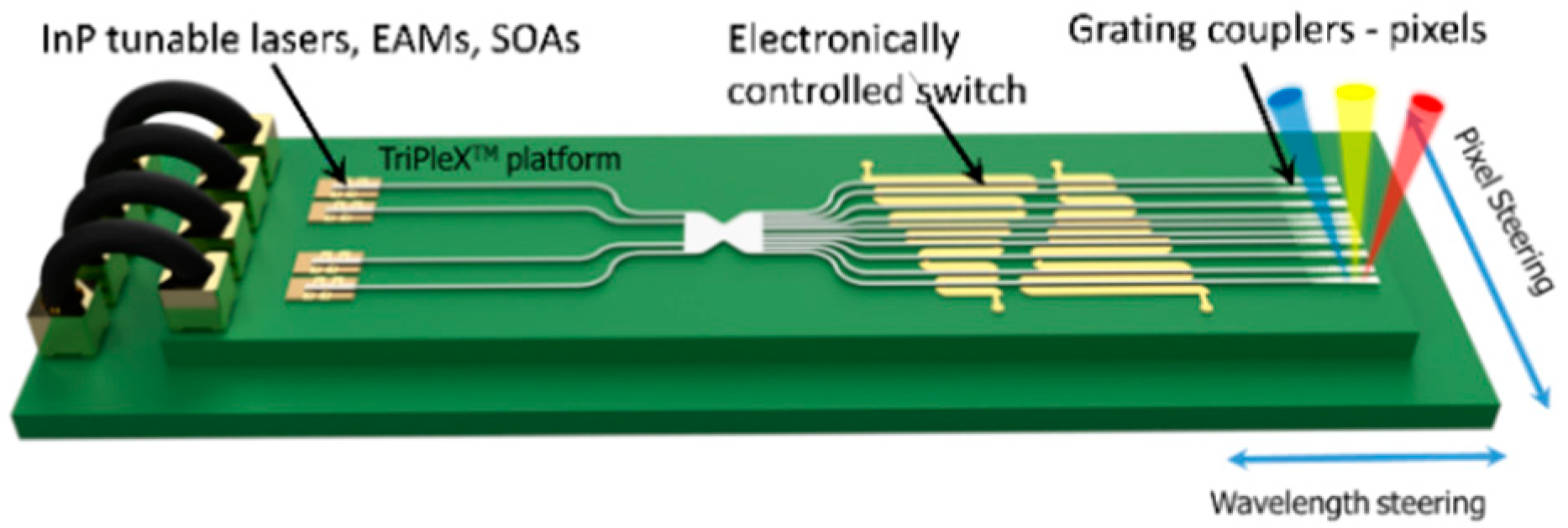
Here, we propose a new class of transmitters relying on PICs offering a fast and large field-of-view OBS for intra-DCN. The transmitter PIC can be based on the hybrid integration of InP elements (i.e., lasers, modulators, amplifiers) on a TriPleX™ platform [
17], as can be seen in
Figure 1. TriPleX waveguides form a new class of integrated-optical planar lightwave circuits using low-cost, CMOS-compatible fabrication equipment.
2.1. Optical Beam Steering Technologies at the Transmitter Side
The OBS is accomplished using two mechanisms. The first mechanism is wavelength tuning. According to calculations, a wide angle of 20° could be achieved using 80 nm wavelength tuning, incorporating one or more tunable laser sources in the vertical direction. In the horizontal direction, the technology could provide similar range with the use of a high number of pixels and phase shifters relying on piezoelectric transducers (PZT) with sub-μW power consumption and ns response time [
20], thus complying with the low energy consumption and low latency requirements of DCNs. The available technology promises the fabrication of up to 1000 pixels with an inter-pixel distance of 20 μm. By using stress-optic tuning with PZT the power consumption will be reduced by a factor of 1000 compared to thermo-optic technologies.
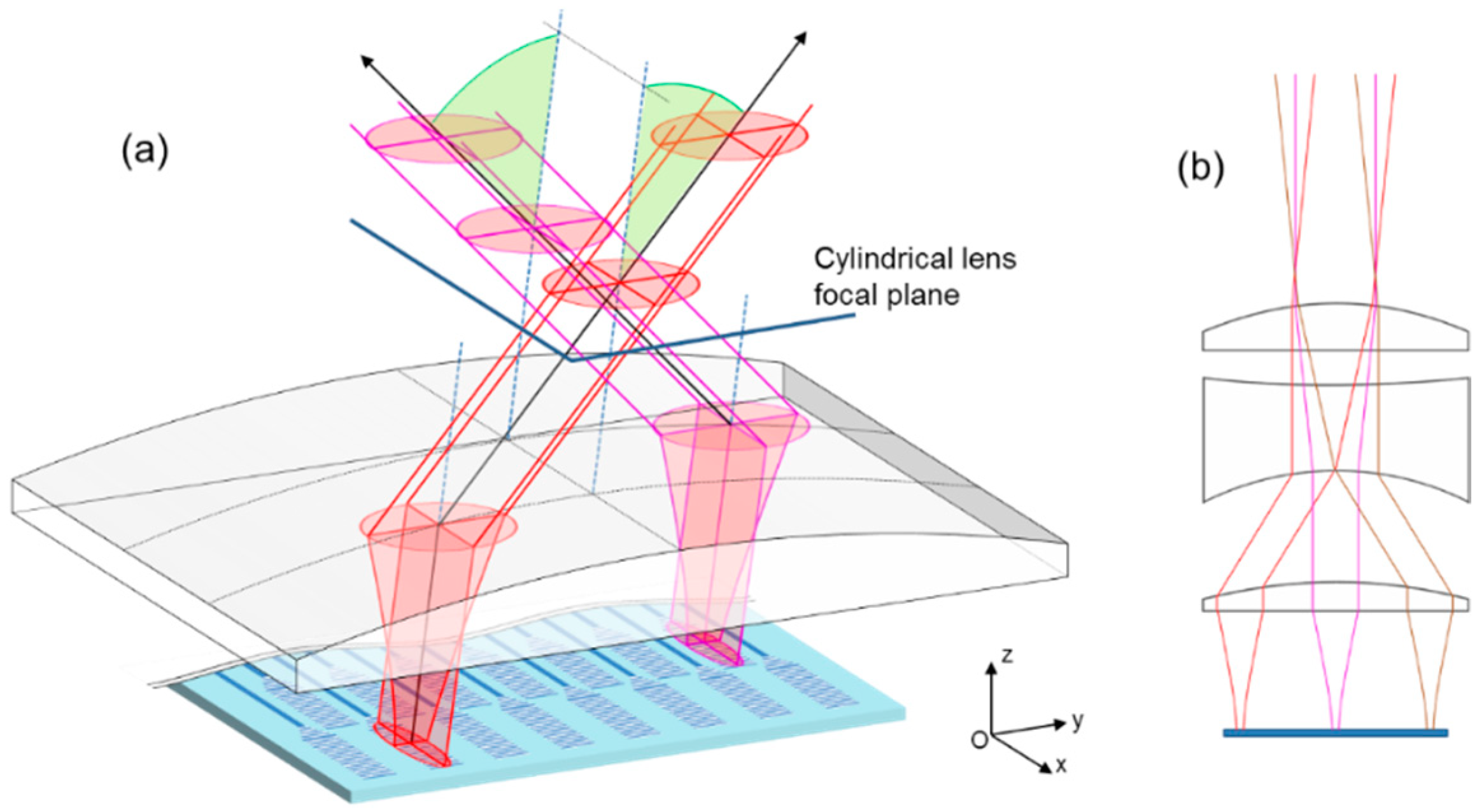
Each pixel is a grating coupler that emits elliptical light beams, with a therefore different divergence in the “vertical” direction (wavelength steering direction) and in the “horizontal” direction (pixel steering direction). Even if the divergence is small, it affects the propagation properties of the beams, thus beam collimation is a prerequisite for the implementation of a practical link with reach exceeding 10 m. A beam size (waist) in the order of a few mm is required to preserve the beam collimated for more than 20 m. In the vertical direction, the divergence is defined by the length and strength of the grating. A length of 2 mm guarantees sub-degree divergence. To control the divergence in the horizontal direction, a lensing system that relies on the use of a cylindrical lens in front of the chip could be incorporated, as is depicted in
Figure 2. In the reception, even if collimated, the beam will have a diameter of a few mm. Hence, a 2D photodiode array should be utilized in order to collect as much as possible of the optical power of the emitted light, as described in detail in the following section.
The radius of the free space beam will vary according to the well-known expression [
21]:
where
is the Rayleigh length, λ is the wavelength, and
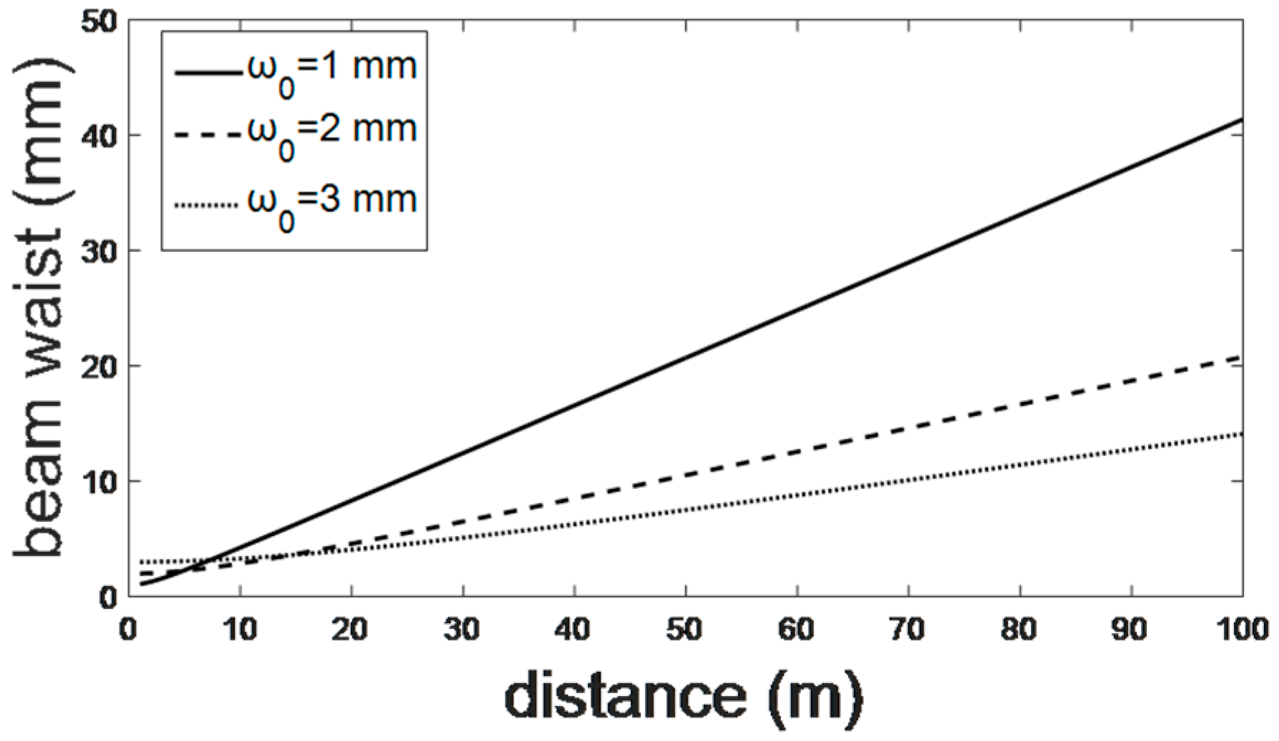
is the beam waist. A typical value of the waist of the beam emitted by the grating coupler is 10 μm. Thus, if a focal length (distance between the grating couplers and the cylindrical lens) of 80 mm is considered, the waist of the collimated beam will be close to 3 mm for a transmitted wavelength of 1.3 μm. Based on (1) and considering that the radius of the beam emitted by the transmitter will be in the order of a few mm, we estimate the radius of the beam as a function of distance for three beam waist values (
Figure 3). It seems that a beam of 3 mm waist could be preserved relatively collimated for more than 30 m. In order to support longer distances, a larger initial beam waist is required.
2.2. Optical Beam Steering Technologies on the Receiver Side
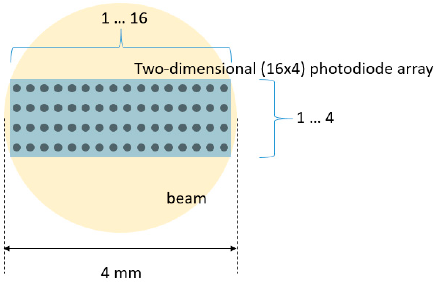
On the receiver side, the solution of a 2D photo diode (PD) array that will combine the high rate performance and the large field of view is proposed. For the bandwidth of 20–25 GHz that is targeted for modern intra-DCN interconnects targeting 100 Gb/s speeds, each single photodiode aperture is as small as 20–25 µm, thus making efficient optical coupling to the largely expanded beam substantially challenging. The PD array at the receiver site will have to contain a large number of single photodiode elements in order to detect a reasonable amount of power. Based on the specifications of commercially available PD arrays [
22], a linear 25 GHz photodiode array featuring integrated lenses, so as to enlarge the aperture per PD to 50 μm, could be used in order to substantially extend the detection area. The lens pitch center-to-center can be as small as 250 µm. With 16 apertures lined up, this would result in a linear PD array chip width of 4 mm (see
Figure 4) corresponding more or less to the beam diameter at the receiver site for moderate distances (<40 m) (see
Figure 3).
With the use of a cylindrical lens in front of the 2D PD array, the amount of power concentrated on the receiver could be substantially increased. If no lens is considered in front of the 2D PD array, then the amount of the detected optical power is the ratio of the detection area over the beam cross-section. Almost 86% of the emitted optical power is contained within a circle of radius
r = ω(
z) if a Gaussian beam is considered. Each photodiode element is hence considered to be a circular detection area with a diameter of around
dPD = 50 µm. The percentage of power reaching its element is equal to (
dPD2/
dbeam2).
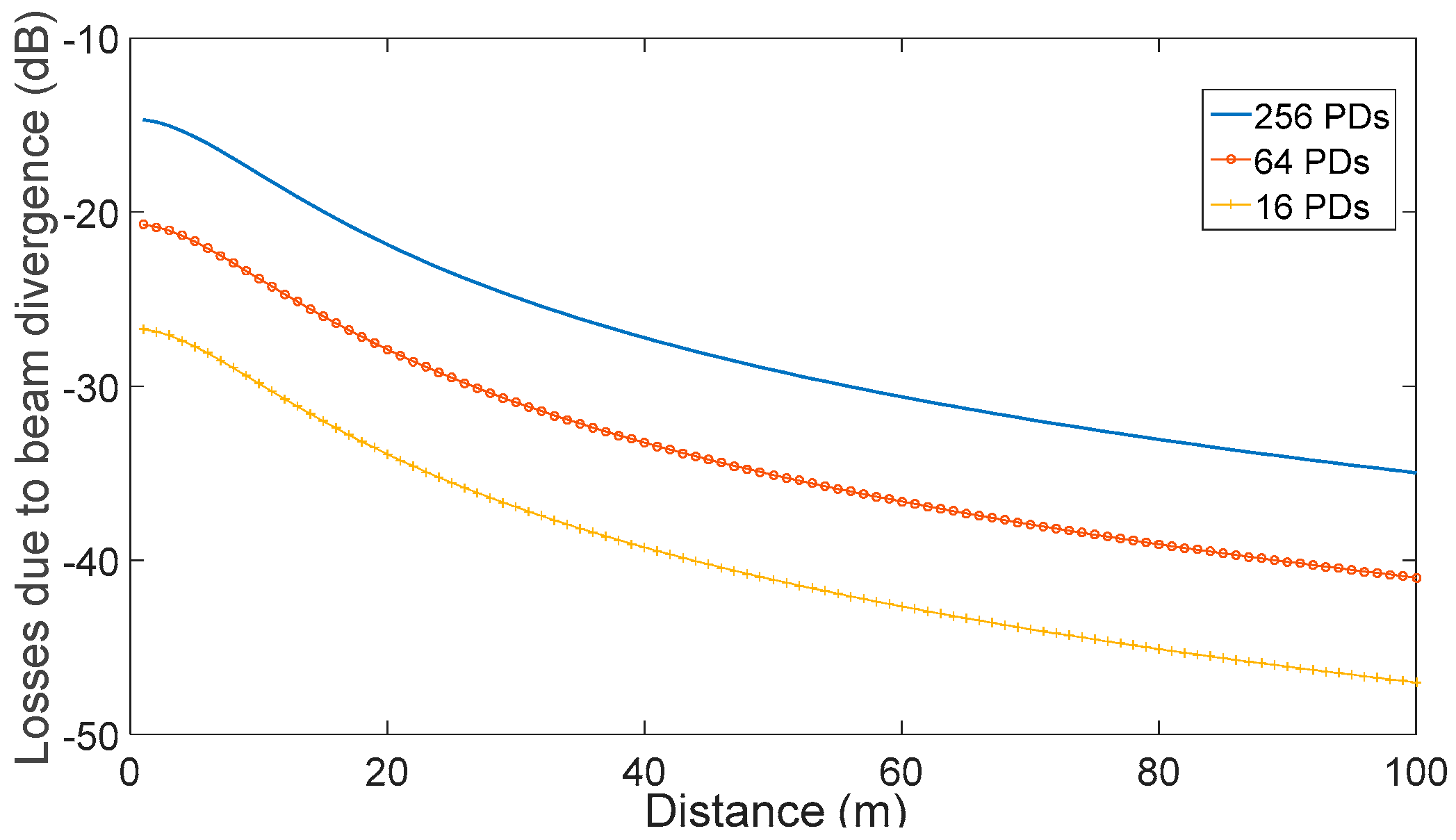
Figure 5 shows the optical losses due to the partial coverage of the PD array by the transmitted beam.
It can be seen that the 2D PD arrays could detect the transmitted signal with losses, due to the high beam cross-section compared to the PD array area, varying from 15 to 25 dB as a function of the number of PDs in the array. The losses also vary with distance due to the broadening of the beam waist, as depicted in
Figure 3. The losses increase by 20 dB after 100 m of propagation and could be less than 25 dB, provided that the distances are shorter than 20 m, the initial beam waist is above 2 mm, and 2D arrays of at least 64 PDs are considered. The amount of 25 dB losses is marginally acceptable as it will be explained in the next paragraph.
2.3. Power Budget
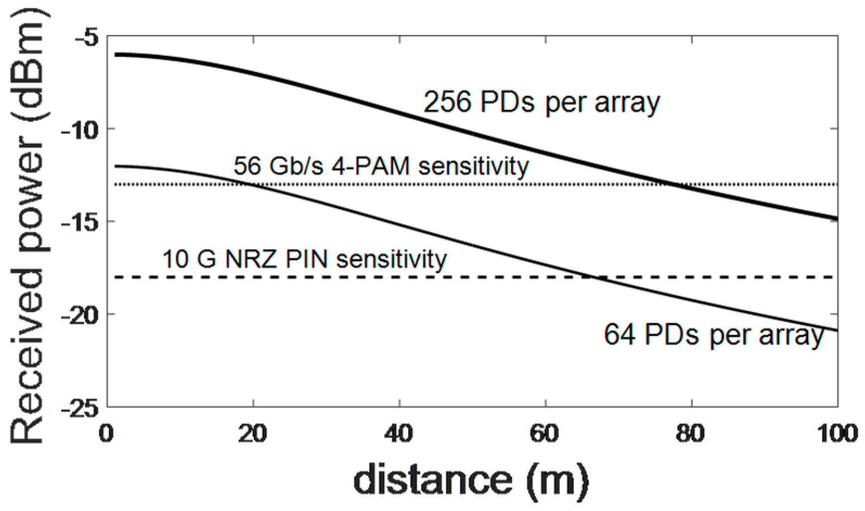
The transmitter could emit 5 dBm out of the chip in order to support longer reach transmission. Assuming an extra lens in front of the 2D array that will roughly improve the detectivity by 5–10 dB (not the same effect for all steering angles), the detected power could scale with distance according to the formula P
REC = P
TRANS + G
CL −
BD, where P
REC is the overall received power, P
TRANS is the transmitted power, G
CL is the gain offered by the use of the lens in front of the 2D array, (~10 dB), L
BD is the loss due to partial coverage and beam divergence already presented in
Figure 5. The results are depicted in
Figure 6 for an initial beam waist equal to 3 mm. We can see that for moderate distances (<50 m), the system could support high bit rate operation (50 Gb/s), and for all distances 10 Gb/s (even 25 Gb/s PAM-4) is feasible especially if avalanche PDs with a sensitivity lower than −20 dBm are considered in the array. Additionally, the distance and the baud rate could be increased if a powerful Forward Error Correction (FEC) is employed, however with a proportional increase of the cost and the complexity. Another way to increase both figures is the utilization of shorter wavelengths (800 nm), which have a higher Rayleigh length.
The transmission losses due to atmospheric absorption are not expected to be more than 1 dB, as the attenuation coefficient for infrared wavelengths in clear weather conditions is less than 0.5 dB/km. An open issue is the effect of DCN conditions on the transmission properties of the optical wireless links, however, this would require detailed investigation and is beyond the scope of this paper. The proposed FSO node has enhanced accuracy and reliability compared to [
12,
14], as it does not include moving objects/mirrors to re-direct the beam.
3. Inter-Data Center Networking Scheme and Results
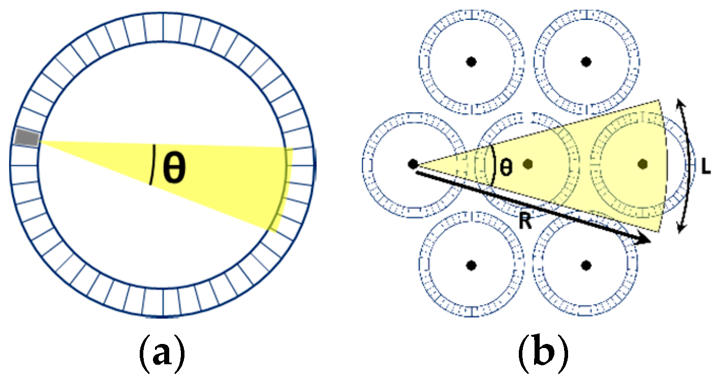
In this section we demonstrate a DCN architecture that could efficiently incorporate the aforementioned devices. With proper DC rack orientation, the transmitter and receiver can have direct line of sight (LoS). We propose a cylindrically shaped cluster with the racks placed on the cluster’s border, as shown in
Figure 7a,b, thus increasing the number of direct inter-rack FSO links.
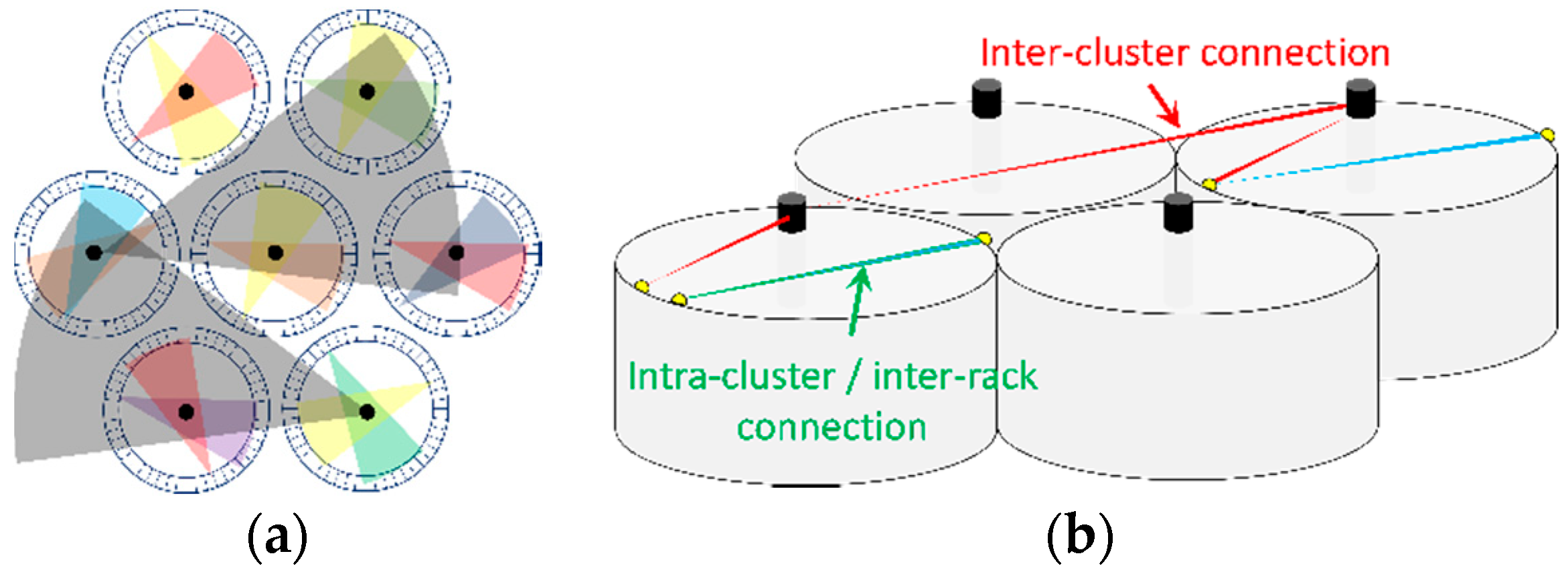
Figure 7b shows a cluster hosting 48 racks (universal standard racks with 50 cm width are considered). The coverage of OBS elements is determined by the steering angle (θ) and the diameter of the cylinder (R). Increasing the number of elements or the tuning range would increase the steering angle. ToR switches will be tier-2 for this architecture. On the other hand, tier-1 switches equipped with FSO transceivers, placed in the center of each cluster (specified with black dot), are utilized for inter-cluster connectivity, as shown in
Figure 8b.
Tier-1 FSO nodes will be placed at a greater height compared to the ToR tier-2 FSO nodes, in order to have direct LoS. Due to 2D OBS capability, tier-2 FSO nodes can communicate using certain wavelengths, while different wavelengths can be exploited for inter-cluster connectivity. The proposed solution will heavily reduce the number of required switches/routers compared to fiber-based solutions [
7]. We present the results on the coverage potential of the proposed FSO nodes considering different practically possible values for the steering angle (10°–20°) and the distance the beam can travel (25 m–100 m). Regarding the cluster size, we assumed two alternatives, hosting 36 or 48 racks. Assuming realistic size racks, we obtain the number of direct inter-cluster and intra-cluster connections that the FSO nodes can establish. The numbers obtained rely on the fact that there is direct LoS between each pair of tier-1 (for inter-cluster) and each pair of tier-2 (inter-rack) FSO nodes. In
Table 1, we present the coverage for inter-cluster FSO nodes, while the inter-rack coverage is summarized in
Table 2. The presented numbers can be increased if spatial multiplexing is employed by using more than one transceiver, positioned in a proper configuration so as to enlarge the field of view of each node. For instance, three transmitters positioned in a row in the inter-cluster communication scenario depicted in
Figure 7b, equivalently to what mobile communications traditionally do using multiple directional antennas to achieve 360-degree coverage, would increase the steering angle to 3θ and would allow all-to-all single-hop communication at the tier-1 level.
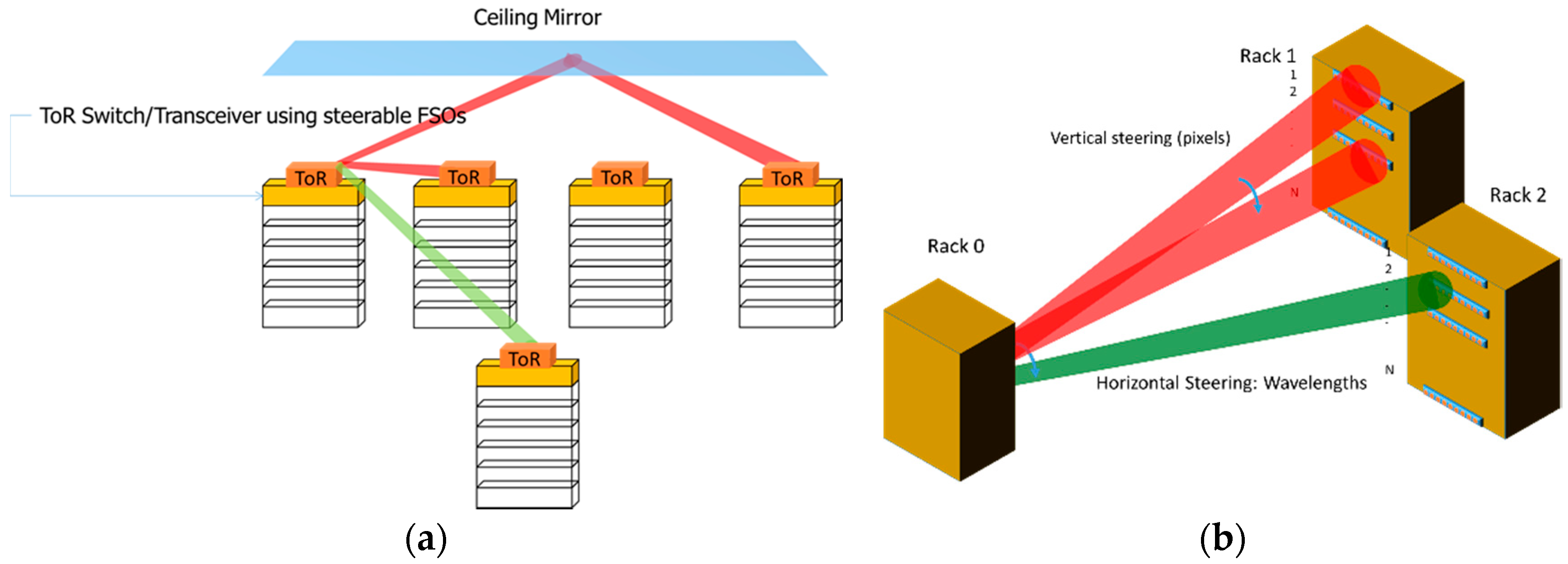
Although the inter-cluster coverage is remarkable, the intra-cluster connectivity suffers from the limited steering angle, which can be alleviated exploiting proper mirrors [
12] as depicted in
Figure 9a. Moreover, the 2D steering capability can be exploited so as to allow for direct, single-hop blade-to-blade communication among different racks. The transceiver of each blade selects the rack using horizontal steering and can select the blade belonging to this rack through vertical steering (see
Figure 9b), enabling flat disaggregated DCN architectures [
23]. Due to the high level of direct inter- and intra-cluster connectivity and ultra-fast optical switching capability envisioned in the solution, the DCN topology can be intelligently re-configured, adapting to rapid traffic changes. Note that the specific devices are able to support radical change in the intra-DCN architecture, enabling random graph topologies which have proved to be more scalable and flexible [
24].

 ,
, 


