Identifying the Contribution of Carrier Shot Noise and Random Carrier Recombination to Excess Frequency Noise in Tunable Lasers


Radio and Optical Communications Research Laboratory, School of Electronic Engineering, Dublin City University, Glasnevin Dublin 9, Ireland
*
Author to whom correspondence should be addressed.
Photonics 2019, 6(1), 4; https://doi.org/10.3390/photonics6010004
Submission received: 30 October 2018
/
Revised: 13 December 2018
/
Accepted: 23 December 2018
/
Published: 5 January 2019
(This article belongs to the Special Issue Lightwave Communications and Optical Networks)
Abstract
:Tunable lasers are necessary devices for modern-day telecommunications and sensing systems. Tunable lasers based on altering the refractive index of the tuning sections of distributed Bragg reflectors (DBR) by varying the injected electrical current show significantly more instantaneous random changes in the instantaneous lasing frequency (or excess FM-noise) compared to non-tunable distributed feedback lasers. We identifies shot noise and random carrier recombination as being the culprits of the excess FM-noise of DBR lasers, and demonstrated this by invoking detailed analytical and numerical analyses of the stochastic carrier fluctuations in the tuning sections, as well as a simplified quasi-static laser tuning model to convert the carrier fluctuations into random instantaneous fluctuations. We found that the spectral density of the FM-noise was mostly in the range 0.5 MHz–10 MHz, and this is in agreement with many independently published results. Our analytical treatment allowed us to conclude that it would be advantageous to reduce the refractive index dependence on the carriers in order to reduce the excess FM-noise while still maintaining the tuning functionality. The simplified numerical model allowed us to create a system simulator to help further develop signal processing techniques to counteract against these instantaneous laser frequency fluctuations.
1. Introduction
Tunable lasers are vital components within every transponder of modern coherent optical communications systems [1,2,3,4,5,6,7,8,9,10,11,12,13,14,15,16,17,18,19].To date, narrow linewidth tunable lasers, with linewidths ~100 kHz based on thermally tuned external cavity lasers, are the tunable laser technology that dominates the market for systems with line rates of 100 Gbit/s, 400 Gbit/s and beyond [7]. The reliance on thermal tuning makes these lasers unsuitable for sub-microsecond wavelength tuning times, as demanded by state-of-the-art transponders for the next-generation passive optical networks (NG-PON2) [2,8]. While NG-PON2 standards aim to deliver line rates of 10 Gbit/s per user, per wavelength, given the rapid rise in data consumption by users and the internet of things, data communication rates will need to increase in excess of 10 Gbit/s per user, with ultra-fast wavelength tuning of the laser transmitters to unused channel slots to maximise the available transmission capacity. Passively tuned, monolithic tunable lasers based on distributed Bragg reflectors (DBR) have been shown to perform wavelength switching at nanosecond switching times [3,4,5,6,13,14,15,16,17]. One issue that needs to be addressed when using DBR-style lasers is the excess FM-noise [18,19,20,21,22]. Excess frequency noise in tunable semiconductor lasers is visible in random frequency drifts of the lasing output. This effect has been described as excess frequency noise, 1/f–noise [15,19], filtered-FM-noise [16,18], and carrier noise [20]. For the purposes of this paper we shall refer to this noise as excess FM-noise, because this noise is in addition to the usual Schawlow–Townes–Henry phase noise present in all semiconductor lasers [23]. For communication systems that employ such tunable lasers, the digital signal processing in the receiver needs to account for the instantaneous frequency drifts that occur on microsecond timescales. Adopting second-order phase-locked loops [19] or employing doubly differential phase encoding [17] can overcome the random frequency offsets caused by the excess FM-noise of DBR-style tunable lasers.
Despite the numerous observations of this excess frequency noise, the spectral profile of this frequency noise follows the same dynamics as the modulation capabilities of the tunable passive sections. We have postulated this in previous work, and attributed contributions from shot noise and dynamic carrier generation to this excess FM-noise [18]. Apart from a detailed simulation work that includes shot noise and random carrier generation [20], to date there has been no explicit confirmation that quantifies the contribution from carrier recombination and shot noise to the FM-noise of tunable lasers. “Shot noise” refers to the randomness of the electronic current arising from the discreetness of electronic charge, and “random carrier recombination” refers to random recombination of electrons and holes within the laser waveguide.
In this study, we quantified the contribution from current shot noise and carrier recombination in the passive tuning sections to the FM-noise of tunable lasers. We numerically solved for the carrier density rate equation in the passive tuning sections, and invoked quasi-static laser dynamics to transform the calculated carrier noise fluctuations into FM-noise spectral density (SD) calculations. We show that the calculated value of the FM-noise SD agreed very well with the many independent measurements of the excess FM-noise in DBR-style lasers [15,16,18,19,20]. We used our analysis to find the laser parameters, both material and physical, that can be used to minimize excess FM-noise. Most of the dependent factors are deep-rooted in nature and thus unchangeable, though we found that while the shot noise increased proportionally to the injected current, the FM-noise increased proportionally to the square of the refractive index dependence on carrier density. Hence, it is possible to lower the excess FM-noise by choosing a laser material with smaller differential refractive index dependence on carrier density while maintaining the overall tuning capability. Our methods show how to numerically reproduce these random instantaneous frequency fluctuations, allowing us to create a system simulator to rapidly test signal processing concepts in order to use these lasers in high-capacity optical communication systems.
2. Theory
We will first briefly review and define the tuning mechanism of tunable DBR-style lasers. More comprehensive explanations can be found in [3,4,5,6]. We concentrate on lasers with a single DBR grating in this paper, though the analysis contained within this paper applies equally to other tunable lasers with sampled DBR gratings that provide for an extended wavelength tuning range exceeding 40 nm [3]. A typical DBR laser structure is shown in Figure 1a. Independent amounts of current are pumped into the different sections. The gain section provides the optical gain and thus invokes the overall lasing action. The current in the other two sections only varies the refractive index (and loss) of those sections, that allow for the laser to be tuned. Figure 1b depicts the tuning mechanism. There are many allowable longitudinal modes determined by the effective length of the device, and the DBR grating section selects a single lasing longitudinal mode, and the phase (tuning) section provides for small tuning of the laser wavelength by adjusting the overall optical length of the device.
Preliminary to the FM-noise analysis, we provide a brief overview of the FM-noise of semiconductor lasers. There is an equivalence between laser linewidth and FM-noise SD, as explained thoroughly in [24]. A purely Lorentzian lineshape corresponds to a flat FM-noise spectral density, whose constant value is proportional to the ‘3 dB linewidth’ [24]. To convert between FM-noise SD and ‘3 dB linewidth’, one needs to multiply the FM-noise by 2π [24]. Due to the common usage of ‘3 dB linewidth’ throughout the photonics community, we chose to scale all of our calculations for FM-noise SD by 2π. Unless stated otherwise, all of the values for the FM-noise SD in this paper are scaled by 2π. Concentrating on evaluating the FM-noise SD allows us to clearly distinguish between the various independent contributions to the laser phase noise. A general expression of the FM-noise spectral density of these DBR lasers is given by [18]:
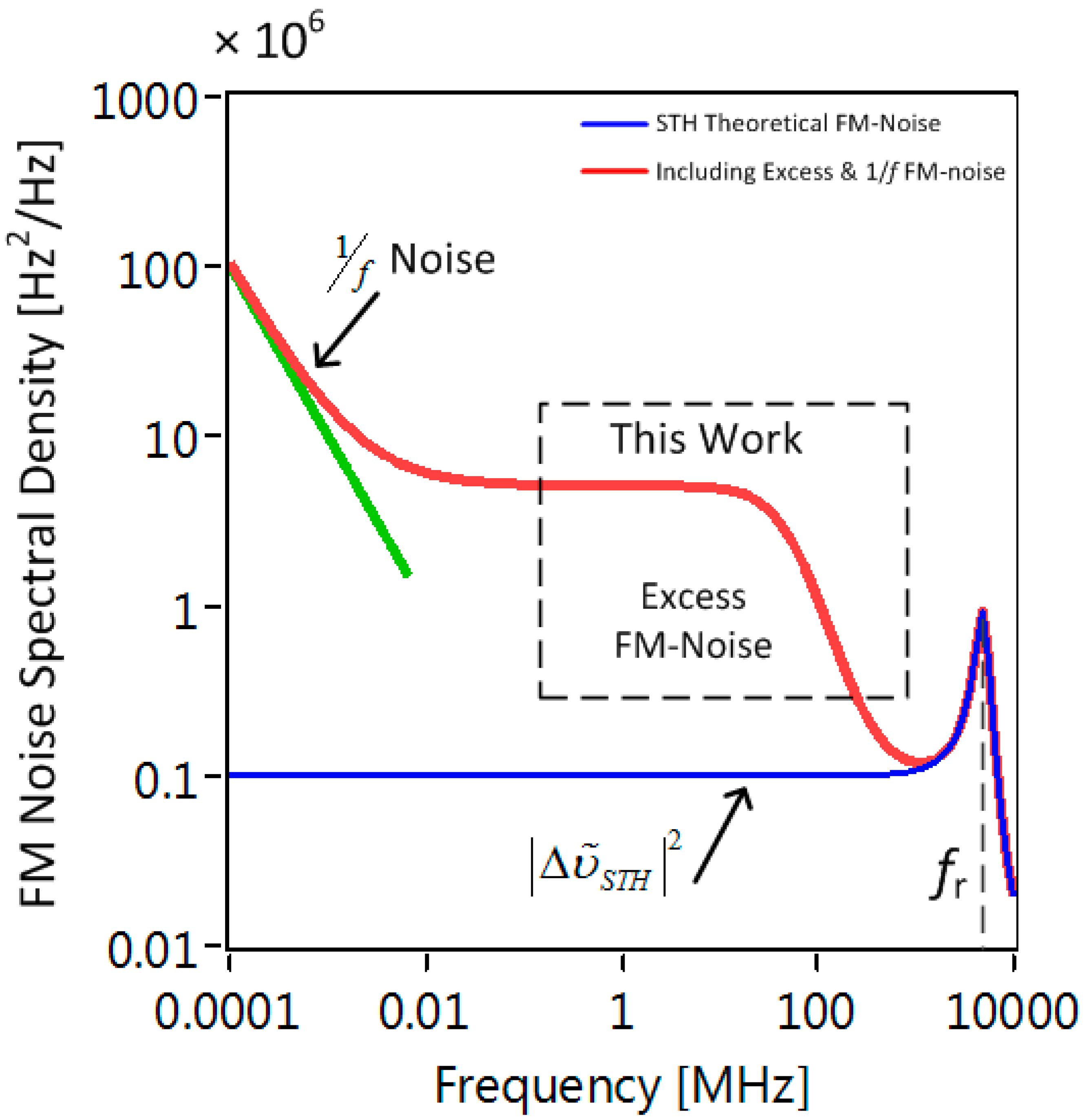
We plotted an exemplar curve using this expression in Figure 2. The first term on the right hand side of (1) is the usual ‘3 dB linewidth’, combined with the relaxation of semiconductor lasers as derived by Henry in [23]. A plot of this first term is given by the blue curve in Figure 2. As the name implies, FM-noise SD is analogous to power spectral density, hence the appearance of the terms in (1). Therefore, the units for FM-noise spectral density conveniently happen to be Hz, though to maintain consistency throughout this paper where we will be analytically solving stochastic differential equations with Langevin contributions, we refer to these SD quantities as . is the FM-noise spectral density that would be interpreted as the “Schawlow–Townes–Henry” or “3 dB linewidth” [23], fr is the relaxation oscillation frequency, and Γ is the damping rate of the relaxation oscillation. Typically, semiconductor lasers are under-damped, hence the peak in the FM-noise SD plot. αH is Henry’s linewidth enhancement factor. The second term on the RHS of (1) describes the excess FM-noise or filtered FM-noise, and has a low-pass type response with cut-off frequency corresponding to the modulation dynamics of the passive tuning section [18,25,26]. It is this type of FM-noise that we are studying in this paper. The third term represents the typical 1/f noise, which is prevalent at low frequencies and is caused by 1/f noise on the drive currents and environmental factors [21,22]. This type of noise depends on the environmental and operating conditions, therefore the value of κ is merely for illustrative purposes. A plot of the full expression in (1) is given by the red curve, showing the excess FM-noise as well as the typical FM-noise of semiconductor lasers. The presence of the excess FM-noise term is typical of DBR-style lasers because the carrier density needed to tune the lasers remains unclamped, and hence carrier density noise transfers directly to the instantaneous frequency noise of the lasers [3,18]. Now that we have given a brief overview of the tuning mechanism and FM-noise characterization, we will numerate the contribution of shot noise to excess FM-noise of DBR-style lasers.
In order to determine the FM-noise, we first need to determine the carrier dynamics. The rate equation describing carrier density dynamics in a passive section is described as:
where is the carrier density, is the injected current, is quantum of electronic charge, is the volume of the region that confines the carriers in the laser, represents the carrier recombination rate, and represents stochastic carrier recombination. can be written as the sum of linear, bimolecular, and Auger recombination terms:
The shot noise term is contained within , and we write , with representing the DC current, and representing the shot noise. By definition for shot noise, the autocorrelation is:
and the corresponding power spectral density is:
We approached the analysis by regarding that the system in (2) has reached a quasi-steady state with in response to the applied DC current . Therefore, is the solution of:
Applying a small-signal analysis of (2), with , we obtain:
We define the carrier lifetime as:
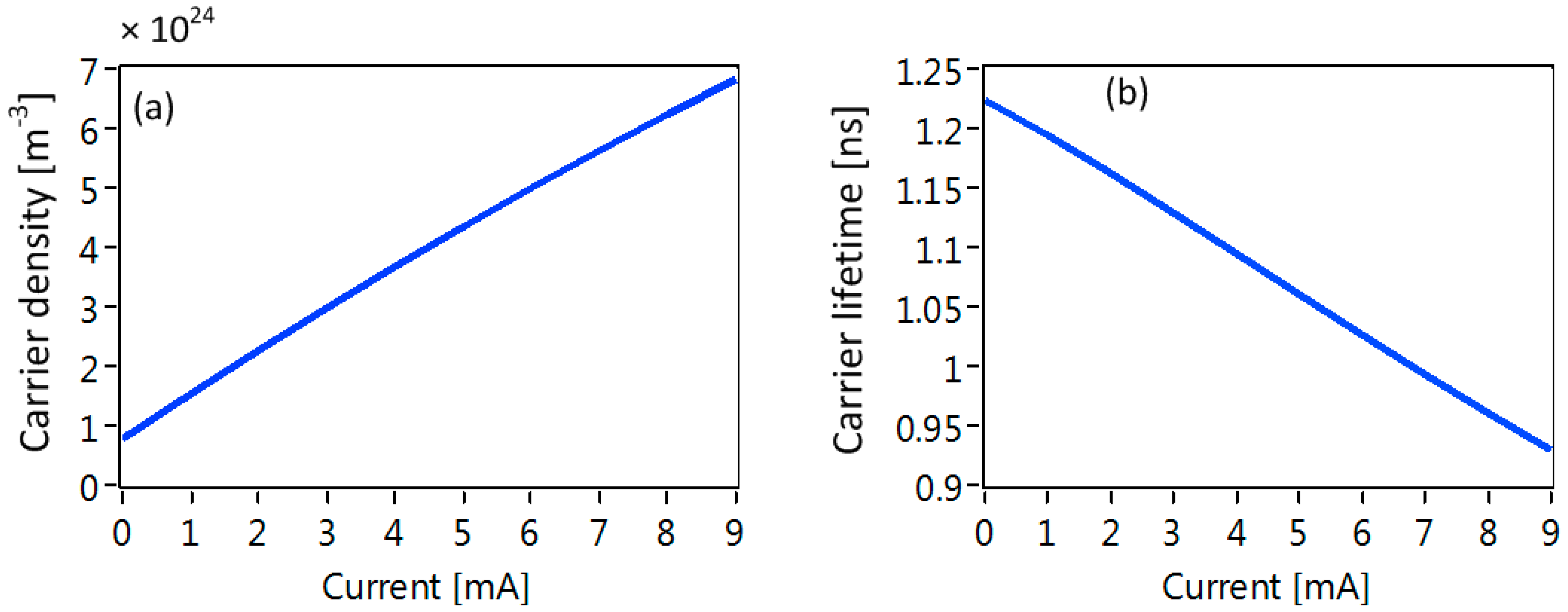
Plots of the steady state level of carrier density and carrier lifetime with respect to the bias current are shown in Figure 3 to reveal the sub-linear behavior of the static carrier density with respect to the bias current and the decrease in carrier lifetime with increasing bias current. The first and last terms on the right hand side of (7) describe the shot noise and random carrier recombination terms. The carrier recombination is considered to be a Markov process, with . The ratio of the magnitudes of the shot noise and dynamic carrier recombination terms is , and was found to be equal in the magnitude of the Langevin term for the shot noise contribution , using the relation in (6).
Assuming that the current noise and carrier recombination have zero correlation, we may add their power spectral densities. Taking the Fourier transform of (7) and calculating the power spectral density, we obtain:
At low frequencies for which , the power spectral density of the carrier fluctuation is:
In order to relate carrier density changes to instantaneous changes in the lasing frequency, we write [3]:
with denoting the lasing frequency and nT denoting the refractive index of the tuning section. We have already described Δn due to the shot noise. To estimate for dυT/dnT, we can approximate the lasing frequency if we know the longitudinal mode spacing and longitudinal mode number. Ignoring dispersion in the frequency dependence of the refractive index, the lasing frequency is an integer multiple of the free spectral range (FSR), υL = mΔυFSR. ΔυFSR is related to the length and refractive index of the laser, and invoking an approximation in [5], we write:
where and are the equivalent refractive index and length of the laser gain and DBR sections. For the tuning section (subscripted by ), is the refractive index and is the length of the tuning section. Using the parameters given in Table 1, we estimate that = 42 GHz. Given a lasing frequency of ~193 THz, we estimate to be of the order of 4096. We can now estimate for using (12) as:
To calculate , we first invoke the Drude model for the refractive index of a free-carrier plasma [3]:
with being the equivalent effective mass of electrons and holes in the InGaAsP region and being the permittivity of free space. In addition to the free carrier plasma, the contribution due to band filling increases the change in refractive index by a factor of = 2 [3]. Therefore, assuming that the group refractive index equals the refractive index, we can write:
For this paper, we set = 1. Nonetheless, this factor is material-dependent, and setting = 1 allows us to set an easily scalable benchmark for the FM-noise SD arising from shot noise. We can now estimate the low frequency portion of the FM-noise spectral density :
The value for the FM-noise SD is straight-forward to calculate and can be estimated using the laser parameters and physical constants listed in Table 1.
3. Results
We create values for using (2). First, we solved for in (6) for a given value of bias current . Then, we created two uncorrelated zero-mean, unity-variance waveforms, with values taken from a Gaussian distribution to create and the shot noise . We took one of the random waveforms and scaled by to create the random carrier recombination, and created the shot noise term using the other random waveform and scaling by , where is the time step used to numerically solve (2). In all our simulations, = 10 ps unless otherwise stated. Once the simulation reached quasi-steady state, i.e., when (6) was fulfilled, we gathered the waveform for and extracted the random part . We calculated for ten different values of bias current applied to the tuning (phase) section, with the current values ranging from 1 to 10 mA. We calculated the spectral density of the carrier fluctuations by taking the squared magnitude of the resulting fast Fourier transforms (FFT) of and scaling by the spectral width of the frequency bins in the FFT.
First, we calculated the SD of the carrier fluctuations and plotted each value of the current in Figure 4. The SD plots were averaged 1000 times for each value of injected current, and every simulation run used different uncorrelated numerical sources for and . The calculated values for the SDs matched exactly with those given by the analytical formula for spectral density of the carrier noise in (10). Note that the roll-off in the FM-noise was due to the equivalent low-pass filtering effect due to the limited carrier dynamics [25,26], with maximum frequency limited to 100 MHz. The horizontal lines in Figure 4 are just a guide to show that the calculated and analytical values match. We then converted the carrier fluctuations to a laser frequency variation using (11).
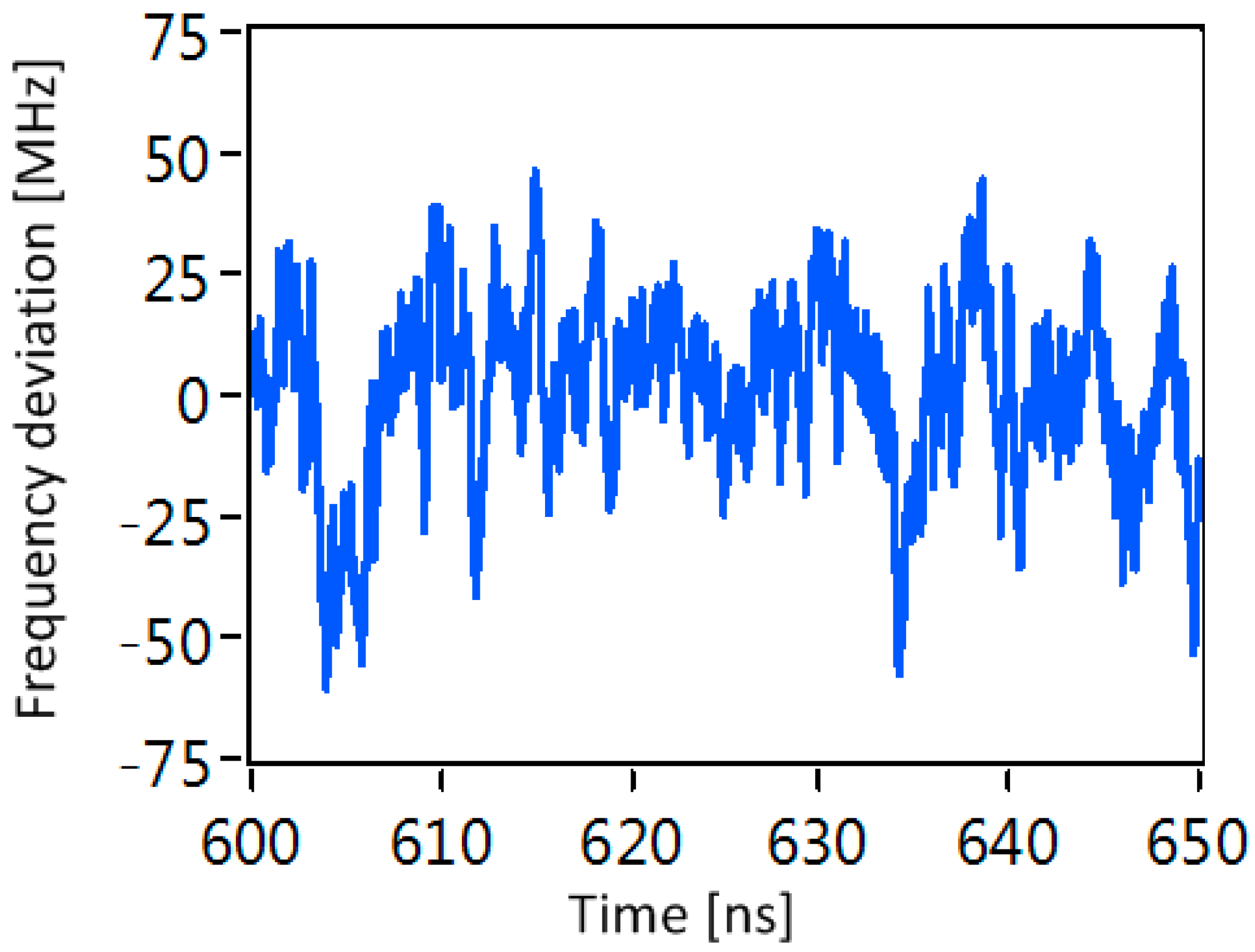
The corresponding FM-noise SD plots are shown in Figure 5. For the parameters and operating conditions used in this paper, we found that the value for the FM-noise ranged from 2.3 MHz to 14.5 MHz, and these values were commensurate with experimental values for the FM-noise SD of this effect varying from 1 MHz to 15 MHz [15,16,18,19], and around 10 MHz from the full simulation [20]. For completeness, we show the instantaneous frequency change of the laser over a 50 ns window in Figure 6. There are implications arising from the large instantaneous frequency shifts: For communication systems, these frequency shifts are directly translated to frequency offsets between the signal and local oscillator laser in the receiver. The frequency offsets add additional unwanted phase shifts from symbol to symbol, and these phase shifts need to be tracked so that they can be eliminated digitally in the receiver. A tuned second-order phase-locked loop [15] or use of modulation formats based on doubly differential phase shift keying alleviates the frequency offsets [17].
From our simple analysis, we can deduce that shot noise from the bias currents is responsible for the excess FM-noise in tunable lasers. Once this had been verified, we were able to explore the implications of this finding by investigating the available options to reduce excess FM-noise in tunable lasers.
4. Implications
The simple analysis in the previous section allows us to explore how to minimise the FM-noise in tunable lasers. The primary goal of a tunable laser is to be able to tune the lasing frequency of the laser by one whole FSR. Therefore, our figure of merit for each laser is to establish the current needed to tune that laser by one whole FSR. The carrier density required to tune the laser by one FSR using (11) and (12) is:
where is the carrier density required to tune the laser by one whole FSR. Approximating using (13) gives:
and using:
We obtain a relation for :
The FM-noise SD at this value of injected current is calculated via (16). Using this value for , inserting for the constituent terms and simplifying gives:
where is the cross-sectional area of the laser waveguide section. Interestingly, this result becomes independent of the length of the tuning section if one assumes that . However, the length of the tuning section may play a role in determining , because is carrier density-dependent. Equation (21) can be simplified further by noting that the lasing wavelength . Then, (21) can be written as:
This result implies that in order to decrease the FM-noise SD of a tunable laser, one must decrease the carrier lifetime, increase the device area, reduce and increase the length of the laser. The carrier lifetime is bias-dependent, with the lifetime shortening as the bias is increased (see Figure 3b). Hence, the cut-off frequency increases and thus the laser experiences more rapid frequency fluctuations, which will have implications at the receiver of a communications system, with the receiver needing to account for faster (albeit smaller) fluctuations of the lasing frequency. Increasing the lateral area of the guided mode requires that care is taken to avoid two or more resonant axial modes to be guided along the structure. Decreasing dn/dN may seem counter-intuitive due to the increased shot noise arising from the extra current needed to obtain an increased value of ΔNFSR. However, since the FM-noise SD depends on I0 and the dependency on the refractive index is (dn/dN)2, it is advantageous to allow an increase in the bias current while enjoying a decrease in the overall FM-noise, though larger input currents will heat up the device more and consideration needs to be given to the contribution of thermal tuning, which counteracts against carrier tuning [25,27]. The only physical parameter that can decrease the in (15) is the effective mass of electrons . This is far from trivial to accomplish, but may be realised through judicious bandgap engineering.
5. Discussion and Conclusions
We have explored the explicit contribution played by shot noise in the excess FM-noise of tunable lasers. Using simple dynamic equations and a quasi-static laser model, we have shown that calculated excess FM-noise for tunable lasers is commensurate with published results. All the published results give values for this excess FM-noise within the range from 1 to 10 MHz. In order to minimise the excess FM-noise, the potential options include increasing the active area slightly, or trying to increase the effective mass of electrons in the tuning sections through bandgap engineering. Our simple numerical approach to generating random frequency fluctuations in the tunable lasers allows for facile incorporation into a much larger communication system level simulator.
Author Contributions
S.O.D.: devised the research plan and implemented the software codes to generate the carrier noise and convert to laser frequency noise. Y.L.: analyzing the results and writing of the paper. L.B.: Funding acquisition, analyzing the results and writing of the manuscript.
Funding
This work was funded through Science Foundation Ireland (12/RC2776) and Enterprise Ireland (IR/2016/0034).
Acknowledgments
The authors are grateful to the anonymous reviewers for their explanation of carrier recovery processes that helped to improve this paper.
Conflicts of Interest
The authors declare no conflicts of interest.
References
- Kikuchi, K. Fundamentals of Coherent Optical Fiber Communications. J. Lightw. Technol. 2016, 34, 157–179. [Google Scholar] [CrossRef]
- ITU-T G.989.1 Next Generation PON 2 Specification; ITU-T: Geneva, Switzerland, 2013.
- Buus, J.; Amann, M.-C.; Blumenthal, D.J. Tunable Laser Diodes and Related Optical Sources, 2nd ed.; Wiley/SPIE Press/IEEE Press: Hoboken, NJ, USA, 2005; ISBN 0-471-20816-7. [Google Scholar]
- Coldren, L. Monolithic tunable diode lasers. IEEE J. Sel. Top. Quantum Electron. 2000, 6, 988–999. [Google Scholar] [CrossRef]
- Coldren, L.A.; Corzine, S.W.; Masanovic, M.L. Diode Lasers Photonic Integrated Circuits; Wiley: Hoboken, NJ, USA, 2012; ISBN 978-0-470-48412-8. [Google Scholar]
- Morthier, G.; Vankwikelberge, P. Handbook of Distributed Feedback Laser Diodes, 2nd ed.; Artech House: Norwood, MA, USA, 2013; ISBN 978-1-608807-701-4. [Google Scholar]
- Daiber, A. Narrow-linewidth tunable external cavity laser for coherent communication. In Proceedings of the 2014 IEEE Photonics Conference, San Diego, CA, USA, 12–16 October 2014. [Google Scholar]
- Zhao, H.; Hu, S.; Zhao, J.; Zhu, Y.; Yu, Y.; Barry, L.P. Chirp-Compensated DBR Lasers for TWDM-PON Applications. IEEE Photonics J. 2015, 7, 7900809. [Google Scholar] [CrossRef]
- Ward, A.; Robbins, D.; Busico, G.; Barton, E.; Ponnampalam, L.; Duck, J.; Whitbread, N.; Williams, P.; Reid, D.; Carter, A.; et al. Widely tunable DS-DBR laser with monolithically integrated SOA: design and performance. IEEE J Sel. Top. Quantum Electron. 2005, 11, 149–156. [Google Scholar] [CrossRef]
- Wesström, J.-O.; Sarlet, G.; Hammerfeldt, S.; Lundqvist, L.; Szabo, P.; Rigole, P.-J. State-of-the-art performance of widely tunable modulated grating Y-branch lasers. In Proceedings of the Optical Fiber Communication Conference, Los Angeles, CA, USA, 22 February 2004. [Google Scholar]
- O’Dowd, R.; O’Duill, S.; Mulvihill, G.; O’Gorman, N.; Yu, Y. Frequency plan and wavelength switching limits for widely tunable semiconductor transmitters. IEEE J. Sel. Top. Quantum Electron. 2001, 7, 259–269. [Google Scholar] [CrossRef]
- Yu, Y.; O’Dowd, R. Influence of mode competition on the fast wavelength switching of an SG-DBR laser. J. Lightw. Technol. 2002, 20, 700–704. [Google Scholar]
- Connolly, E.; Smyth, F.; Mishra, A.K.; Kaszubowska-Anandarajah, A.; Barry, L.P. Cross-Channel Interference Due to Wavelength Drift of Tunable Lasers in DWDM Networks. IEEE Photonics Technol. Lett. 2007, 19, 616–618. [Google Scholar] [CrossRef] [Green Version]
- Browning, C.; Shi, K.; Ellis, A.D.; Barry, L.P. Optical Burst-Switched SSB-OFDM Using a Fast Switching SG-DBR Laser. J. Opt. Commun. Netw. 2013, 5, 994–1000. [Google Scholar] [CrossRef]
- Huynh, T.N.; Nguyen, A.T.; Ng, W.-C.; Nguyen, L.; Rusch, L.A.; Barry, L.P. BER Performance of Coherent Optical Communications Systems Employing Monolithic Tunable Lasers with Excess Phase Noise. J. Lightw. Technol. 2014, 32, 1973–1980. [Google Scholar] [CrossRef]
- Maher, R.; Savory, S.J.; Thomsen, B.C. Fast Wavelength Switching Transceiver for a Virtualized Coherent Optical Network. J. Lightw. Technol. 2015, 33, 1007–1013. [Google Scholar] [CrossRef]
- Walsh, A.J.; Mountjoy, J.; Shams, H.; Fagan, A.; Ellis, A.D.; Barry, L.P. Highly Robust Dual-Polarization Doubly Differential PSK Coherent Optical Packet Receiver for Energy Efficient Reconfigurable Networks. J. Lightw. Technol. 2015, 33, 5218–5226. [Google Scholar] [CrossRef]
- Huynh, T.N.; Dúill, S.P.Ó.; Nguyen, L.; Rusch, L.A.; Barry, L.P. Simple analytical model for low-frequency frequency-modulation noise of monolithic tunable lasers. Appl. Opt. 2014, 53, 830–835. [Google Scholar] [CrossRef] [PubMed]
- Huynh, T.N.; Nguyen, L.; Barry, L.P. Phase Noise Characterization of SGDBR Lasers Using Phase Modulation Detection Method with Delayed Self-Heterodyne Measurements. J. Lightw. Technol. 2013, 31, 1300–1308. [Google Scholar] [CrossRef]
- Liu, F.; Lin, Y.; Liu, Y.; Anthur, A.P.; Yu, Y.; Barry, L.P. Investigation into the Phase Noise of Modulated Grating Y-Branch Lasers. IEEE J. Sel. Top. Quantum Electron. 2017, 23, 1–9. [Google Scholar] [CrossRef]
- Amann, M.-C.; Hakimi, R.; Borchert, B.; Illek, S. Linewidth broadening by 1/f noise in wavelength-tunable laser diodes. Appl. Phys. Lett. 1997, 70, 1512–1514. [Google Scholar] [CrossRef]
- Duan, G.; Gallion, P. Drive current noise induced linewidth in tunable multielectrode lasers. IEEE Photonics Technol. Lett. 1991, 3, 302–304. [Google Scholar] [CrossRef]
- Henry, C. Theory of the phase noise and power spectrum of a single mode injection laser. IEEE J. Quantum Electron. 1983, 19, 1391–1397. [Google Scholar] [CrossRef]
- Kikuchi, K. Characterization of semiconductor-laser phase noise and estimation of bit-error rate performance with low-speed offline digital coherent receivers. Opt. Express 2012, 20, 5291–5302. [Google Scholar] [CrossRef]
- Yu, Y.; Mulvihill, G.; O’Duill, S.; O’Dowd, R. Performance implications of wide-band lasers for FSK modulation labeling scheme. IEEE Photonics Technol. Lett. 2004, 16, 39–41. [Google Scholar]
- O’Dowd, R.; Yu, Y.; Mulvihill, G.; O’Duill, S.; Morthier, G.; Moeyersoon, B. Transmitters for two-tier optical data-packet labellingin advanced IP networks. IEE Proc. Optoelectron. 2005, 152, 163–169. [Google Scholar] [CrossRef]
- Mulvihill, G.; O’Dowd, R. Thermal transient measurement, modeling, and compensation of a widely tunable laser for an optically switched network. J. Lightw. Technol. 2005, 23, 4101–4109. [Google Scholar] [CrossRef]
Figure 1.
(a) Simplified schematic of a tunable distributed Bragg reflector (DBR) laser. (b) Schematic of the tuning mechanism of DBR lasers.
Figure 1.
(a) Simplified schematic of a tunable distributed Bragg reflector (DBR) laser. (b) Schematic of the tuning mechanism of DBR lasers.

Figure 2.
Typical FM-noise spectral density (SD) profile of tunable lasers. The blue curve represents a theoretical FM-noise SD curve of semiconductor lasers without any 1/f noise nor excess FM-noise. The red curve shows the FM-noise of monolithic tunable lasers. The excess FM-noise portion is indicated, and this is the portion of the FM-noise curve that we concentrate on in this paper. At lower frequencies below 100 kHz, the 1/f FM-noise dominates the FM-noise spectrum. The green line denotes the sole contribution to 1/f FM-noise. Note that the 1/f FM-Noise is added for illustrative purposes and that log scales were used for both axes.

Figure 3.
(a) Calculated static carrier density with respect to injected current. (b) Calculated carrier lifetime with respect to injected current. The values of the laser parameters are listed in Table 1.
Figure 3.
(a) Calculated static carrier density with respect to injected current. (b) Calculated carrier lifetime with respect to injected current. The values of the laser parameters are listed in Table 1.

Figure 4.
Calculated SD of the carrier fluctuations. The bias current increases from 1 to 10 mA. The horizontal lines indicate analytical calculations of the carrier fluctuations SD. Note: log scales used.
Figure 4.
Calculated SD of the carrier fluctuations. The bias current increases from 1 to 10 mA. The horizontal lines indicate analytical calculations of the carrier fluctuations SD. Note: log scales used.

Figure 5.
Excess FM-noise SD calculations corresponding to the carrier fluctuations in Figure 4. The bias current is increased from 1 to 10 mA. Note: log scales used.
Figure 5.
Excess FM-noise SD calculations corresponding to the carrier fluctuations in Figure 4. The bias current is increased from 1 to 10 mA. Note: log scales used.

Figure 6.
Temporal trace of the instantaneous laser frequency fluctuations, with the tuning current set to 10 mA and using the parameters in Table 1. The instantaneous frequency can vary by in excess of 50 MHz.
Figure 6.
Temporal trace of the instantaneous laser frequency fluctuations, with the tuning current set to 10 mA and using the parameters in Table 1. The instantaneous frequency can vary by in excess of 50 MHz.


Table 1.
Laser parameters and physical constants.
| Symbol | Quantity | Value and Units |
|---|---|---|
| A | Shockley–Read–Hall recombination coefficient | 8 × 10⁸ s−1 |
| B | Bimolecular recombination coefficient | 1 × 10⁻¹⁷ m3/s |
| C | Auger recombination coefficient | 1 × 10−41 m6/s |
| e | Quantum of electronic charge | 1.6 × 10⁻¹⁹ C |
| V | Volume of tuning section | 10 × 10−18 m3 |
| neq | Equivalent refractive index of laser other than the tuning section | 3.5 |
| Leq | Equivalent length of laser excluding the tuning section | 1 mm |
| nT | Refractive index of tuning section | 3.5 |
| Strength of 1/f FM noise | 1 × 10¹⁰ s | |
| LT | Length of tuning section | 100 µm |
| Lasing wavelength with nT = 3.5 | 193.00 THz | |
| Equivalent effective mass of electrons in InGaAsP | 0.02 × 9.1 × 10−31 kg | |
| Permittivity of free space | 8.85 × 10⁻¹² F/m | |
| K | Excess refractive index factor | 4 |
© 2019 by the authors. Licensee MDPI, Basel, Switzerland. This article is an open access article distributed under the terms and conditions of the Creative Commons Attribution (CC BY) license (http://creativecommons.org/licenses/by/4.0/).
Share and Cite
MDPI and ACS Style
O’Duill, S.; Lin, Y.; Barry, L. Identifying the Contribution of Carrier Shot Noise and Random Carrier Recombination to Excess Frequency Noise in Tunable Lasers. Photonics 2019, 6, 4. https://doi.org/10.3390/photonics6010004
AMA Style
O’Duill S, Lin Y, Barry L. Identifying the Contribution of Carrier Shot Noise and Random Carrier Recombination to Excess Frequency Noise in Tunable Lasers. Photonics. 2019; 6(1):4. https://doi.org/10.3390/photonics6010004
Chicago/Turabian StyleO’Duill, Sean, Yi Lin, and Liam Barry. 2019. "Identifying the Contribution of Carrier Shot Noise and Random Carrier Recombination to Excess Frequency Noise in Tunable Lasers" Photonics 6, no. 1: 4. https://doi.org/10.3390/photonics6010004
Note that from the first issue of 2016, this journal uses article numbers instead of page numbers. See further details here.