Article

Influence of the Lithium Cation Desolvation Process at the Electrolyte/Electrode Interface on the Performance of Lithium Batteries

by
Olga V. Yarmolenko
1,*,
Guzaliya R. Baymuratova
1,
Kyunsylu G. Khatmullina
1,2,
Galiya Z. Tulibayeva
1,
Alena V. Yudina
1,
Tatiana A. Savinykh
1,
Igor K. Yakushchenko
1,
Pavel A. Troshin
1 and
Alexander F. Shestakov
1,3
1
Federal Research Center of Problems of Chemical Physics and Medicinal Chemistry RAS, 142432 Chernogolovka, Russia
2
Department of Chemistry and Electrochemical Energy, Institute of Energy Efficiency and Hydrogen Technologies (IEEHT), National Research University «Moscow Power Engineering Institute», 111250 Moscow, Russia
3
Faculty of Fundamental Physical and Chemical Engineering, M. V. Lomonosov Moscow State University, 119991 Moscow, Russia
*
Author to whom correspondence should be addressed.
Inorganics 2022, 10(11), 176; https://doi.org/10.3390/inorganics10110176
Submission received: 21 September 2022 / Revised: 18 October 2022 / Accepted: 21 October 2022 / Published: 25 October 2022
(This article belongs to the Special Issue Beyond Lithium-Ion Battery Technology)

Abstract

:
The article considers the effect of the solvate environment of the lithium cation in various aprotic solvents.The redox reactions of electrodes made from a polymeric condensation product of triquinoyl with 1,2,4,5-tetraaminobenzene are studied. A 1 M LiPF6 solution was used as an electrolyte, in either ethylene carbonate/dimethyl carbonate (EC/DMC) or tetraglyme. Based on the electrochemical studies and quantum chemical modeling, it was shown that the desolvation of lithium cations in the tetraglyme-based electrolyte makes it possible to obtain a capacity close to the theoretical one (up to 546 mAh g−1) and only 125 mAh g−1 for the EC/DMC electrolyte. This decrease is due to the fact that the lithium cation adds to the functional groups of the organic material with two dimethyl carbonate molecules, as well as the PF6 anion.

Graphical Abstract

1. Introduction

Lithium-organic power sources are of great interest to developers of new mobile energy sources. Works [1,2,3,4,5,6,7,8,9,10] are devoted to the results of the last 5 years’ development of power sources based on lithium, sodium, and potassium electrochemical systems. Organic electrodes have many advantages over their inorganic counterparts; namely, low cost, environmental friendliness, high stability, and versatility for any ion size.
Lithium-ion batteries are known to use liquid electrolytes that are based on 1 M LiPF6 in a mixture of carbonate solvents [11,12,13]. The main component is ethylene carbonate (EC), which has a high dielectric constant (95.3) and is a constituent of the solid electrolyte interface (SEI) at the anode surface. Since EC exists in a solid state at ambient temperature, alkyl carbonate co-solvents, such as dimethyl carbonate (DMC), can be used.
When developing lithium-organic batteries, researchers also began to use this electrolyte composition. However, testing of cells with this electrolyte have shown that the organic electrode dissolves in carbonate electrolytes during cycling. This drawback should be eliminated with the transition to polymeric organic electrode materials. However, polymeric organic electrodes still show a drop in capacity in carbonate solvents.
Previously, we carried out a comparative study of the stability of the organic lithium battery with the polyimide cathode in two different electrolytes: 1 M LiPF6 in EC/DMC (1:1) and 1 M LiN(SO2CF3)2 in a dioxolane/dimethoxyethane (DOL/DME) (2:1) mixture [14]. In this work, electrochemical impedance spectroscopy showed the difference in the formation of SEI both on the lithium anode and at the cathode electrolyte interface (CEI) on the polyimide cathode. Both layers were much larger in the case of 1 M LiPF6 in EC/DMC (1:1).
As a further step, we continued to study the reason for a decrease in the discharge capacity of organic electrodes in the 1 M LiPF6 in EC/DMC electrolyte. For this purpose, we used an electrolyte based on a solution of LiPF6 in tetraglyme G4 (tetraethylene glycol dimethyl ether, CH3O[CH2CH2O]4CH3) [15,16,17,18]. Since tetraglyme is not a carbonate solvent, it practically does not react with the electrode surface to form SEI and CEI, and this makes it possible to exclude the influence of this process [19]. In addition, tetraglyme has a high boiling point and an enhanced viscosity (Table S1, ESI), and is non-toxic and safer than DMC (flash point 141 °C and 18 °C, respectively). Owing to this, tetraglyme is promising for use in power sources with alkaline metal anodes.
In this research, we used the polymer PTTA, a polymeric condensation product of cyclohexane-1,2,3,4,5,6-hexone (triquinoyl) with benzene-1,2,4,5-tetramine tetrahydrochloride, which was synthesized and studied in detail in [20,21,22].
Previously, in the study of PTTA in lithium cells [20], an unexpectedly strong effect of the addition of 5 wt% benzo-15-crown-5 in 1 M LiPF6 in EC/DMC (1:1 v/v) was found. For example, it was shown in [20] that the discharge capacity of PTTA increased by a factor of 3 (344 mAh g−1) in the presence of only 5 wt% crown ether in the electrolyte composition. It is known that crown ethers can “extract” metal ions from solvate shells of solvents [23,24,25].
Thus, the purpose of this work was to study the effect of the lithium cation desolvation process at the electrolyte/PTTA organic electrode interface on the performance of the electrochemical system. Two compositions were studied as electrolytes: 1 M LiPF6 in EC/DMC (1:1 v/v) and 1 M LiPF6 in tetraglyme.

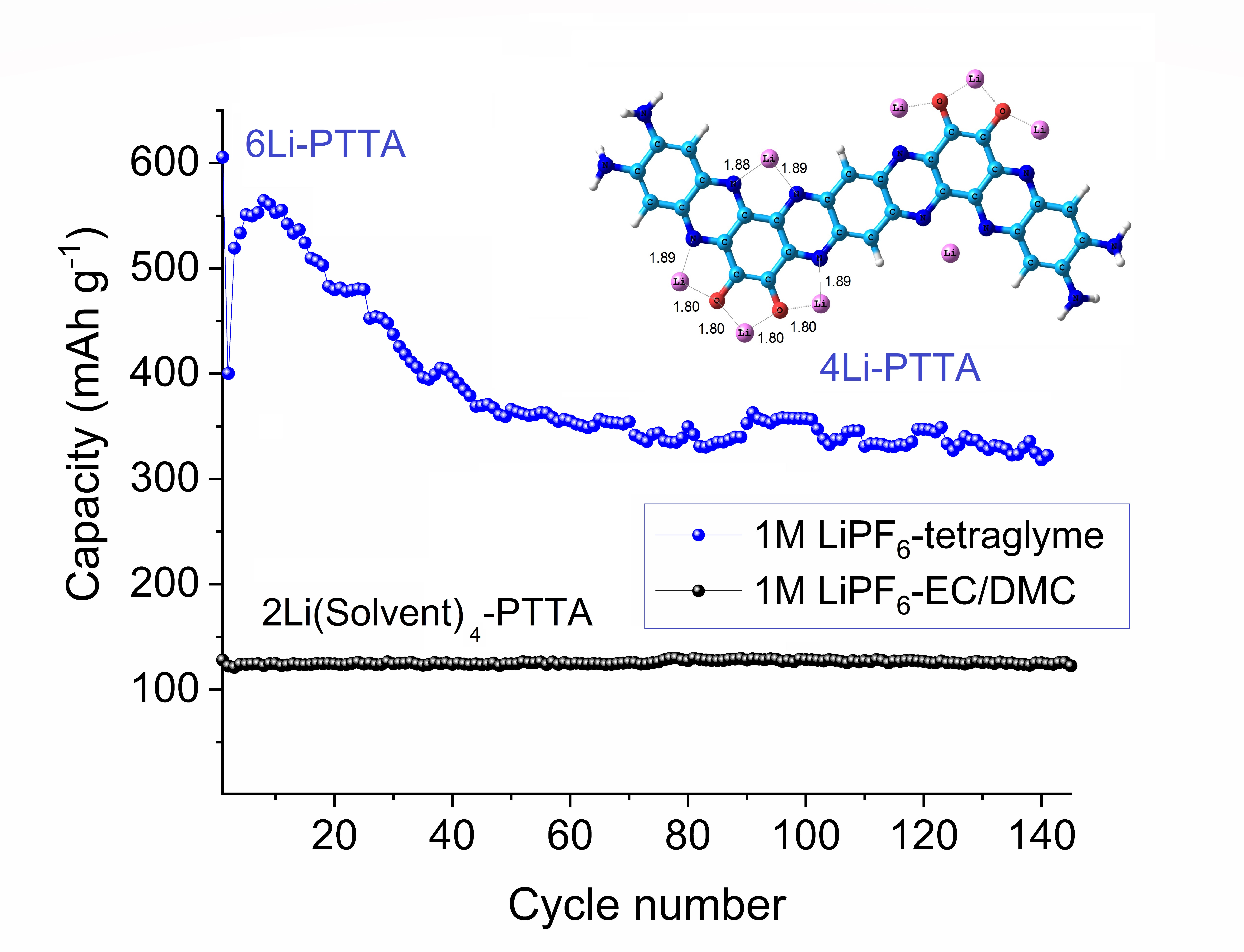
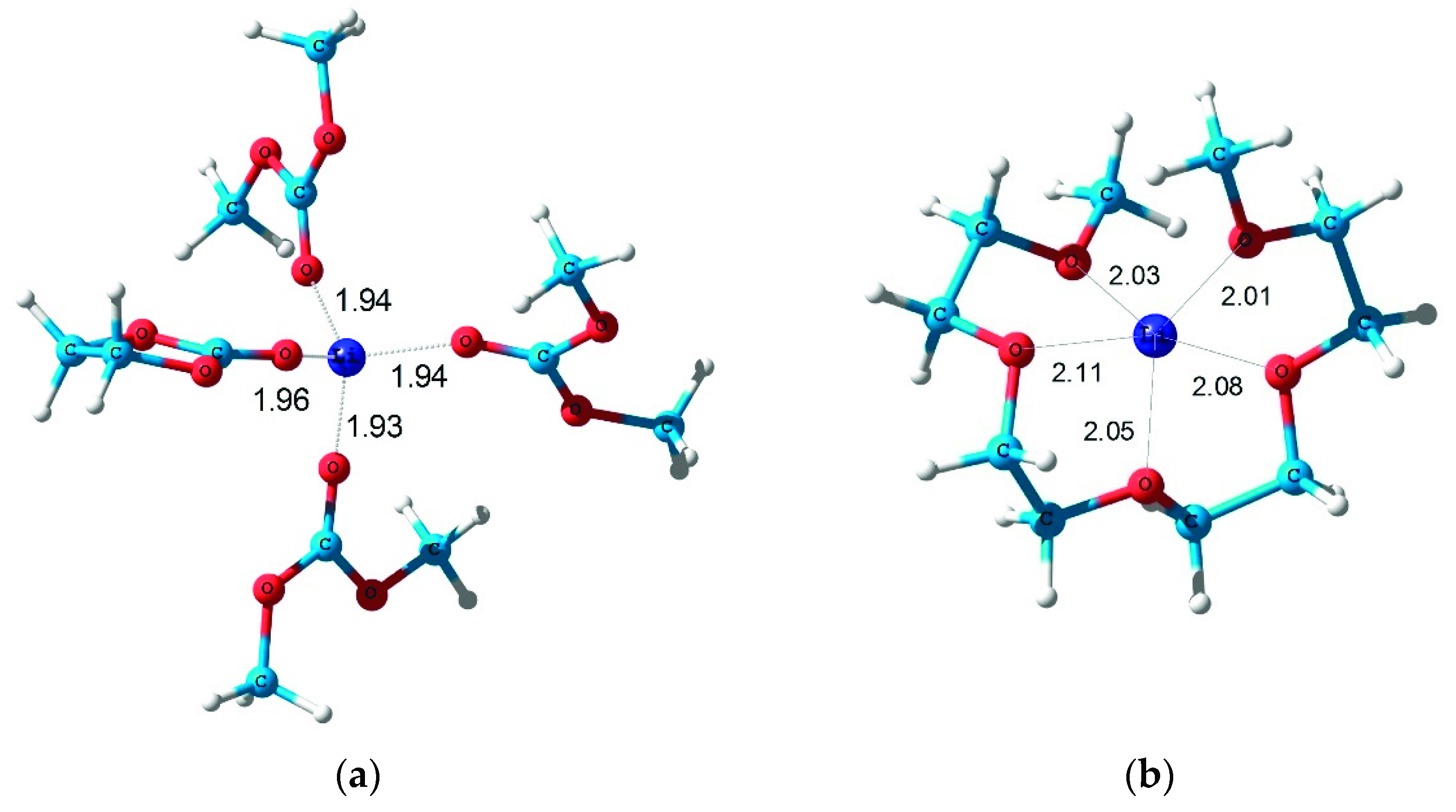
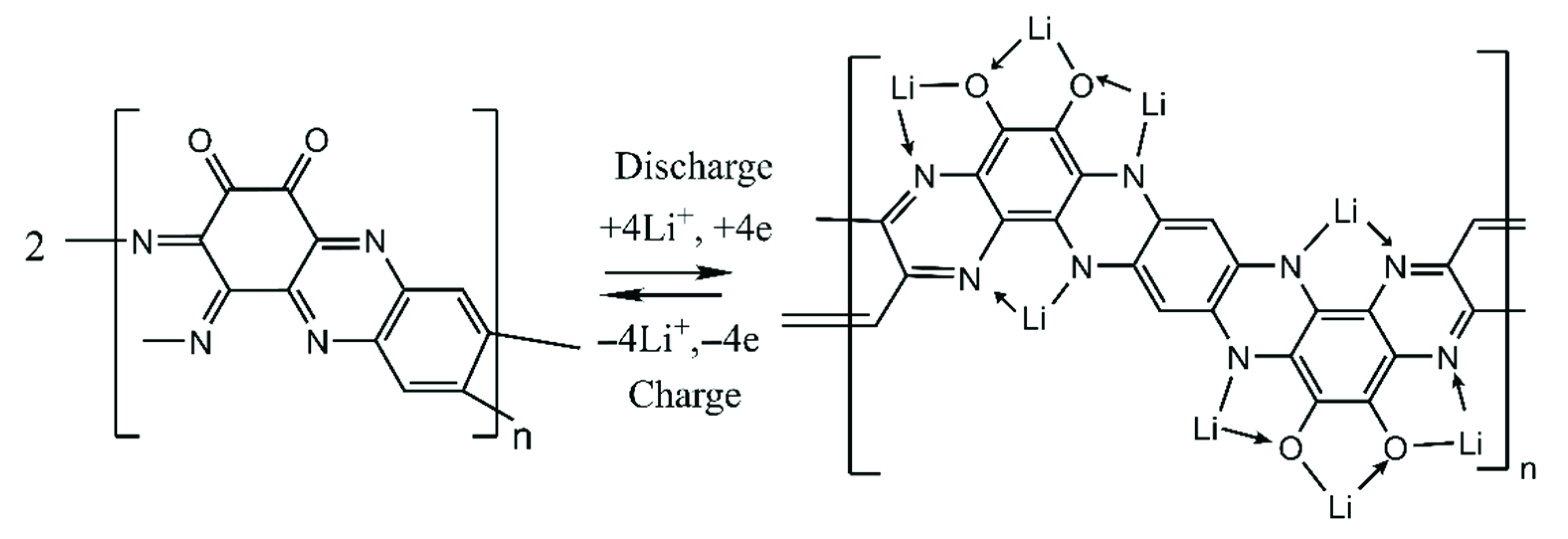
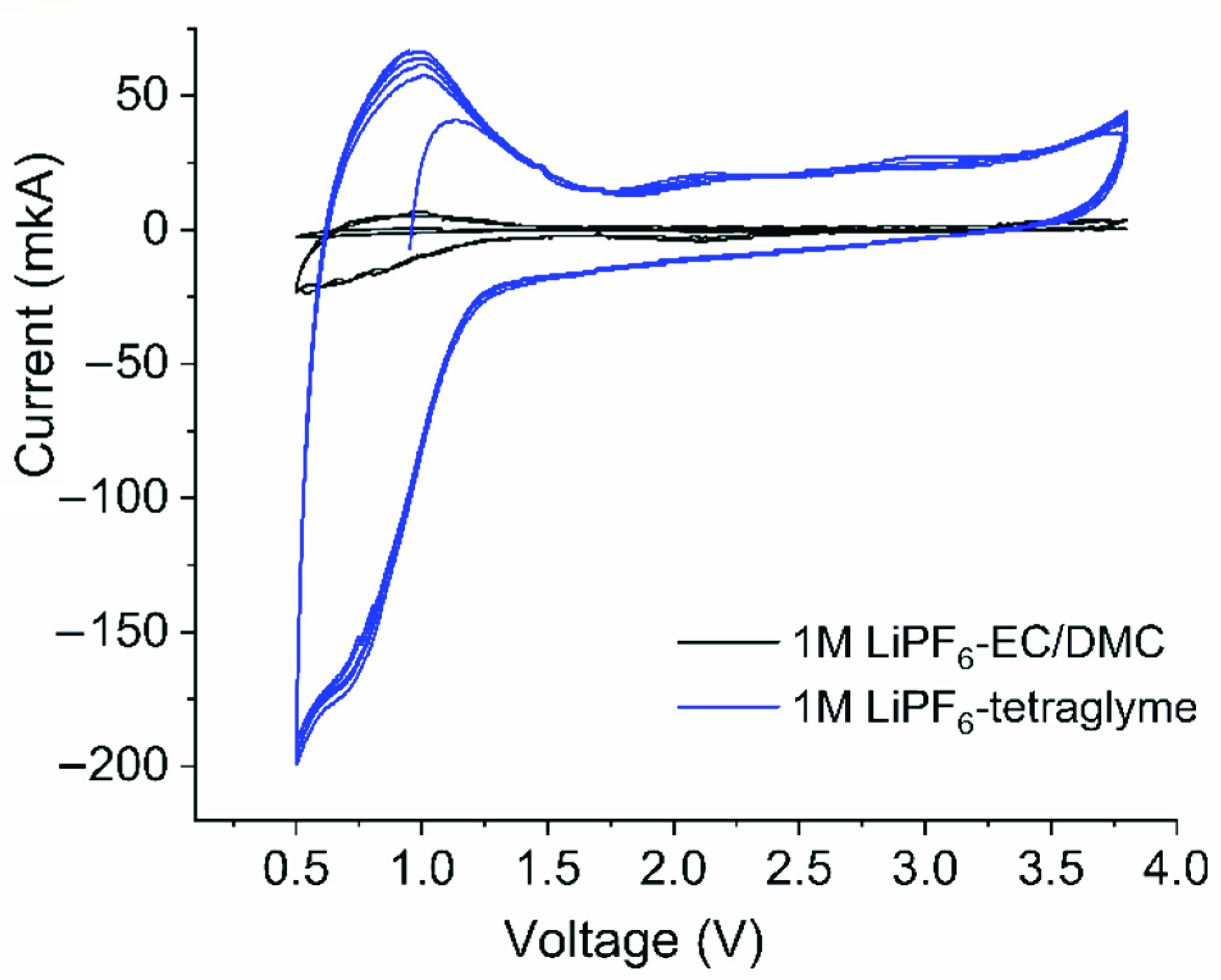
2. Results and Discussions

Figure 1 shows the structures of the solvate complexes of the Li+ cation in the EC/DMC and tetraglyme electrolytes, according to the quantum chemical modeling data. The outer radius of the solvate complexes is 10 Å (Figure 1a) and 5.7 Å (Figure 1b).
The results of the quantum chemical modeling of the complexes with EC/DMC and tetraglyme are consistent with the calculation data of other authors [26,27]. It should be noted that for concentrated solutions (1 M), the solvate shell in the EC/DMC electrolyte consists of only 1 EC molecule and 3 DMC molecules, and only in highly dilute solutions are 2 EC molecules and 2 DMC molecules are coordinated to the lithium ion [26].
Scheme 1 shows the electrochemical redox transformation of PTTA accompanying the charge and discharge of the cell, which follows from the quantum chemical calculations [20].
Figure 2 shows the cyclic voltammetry (CV) results of the Li//PTTA cells with various electrolytes in a voltage range of 0.5–3.8 V vs. Li+/Li.
Figure 2 shows the PTTA characteristic peak in a range of 0.5–1.25 V vs. Li+/Li. This is probably due to the participation of carbon in the redox process, but its function as an electron carrier is more important. If we exclude the cycling range in a range of 0.5–1.25 V, then high organic material capacity values cannot be achieved, and the contribution of the carbon capacity to the total capacity of the electrode material does not exceed 15–20%.
The PTTA polymer has a multistep redox transition in the range from 1.25 to 3.8 V vs. Li+/Li, which does not separate into individual peaks. As shown by the quantum chemical calculations for the oligomer of two units, “theoretical specific stored energies are 2.3, 2.2, 1.9, 1.8, and 1.0 eV per Li atom when 1 to 5 metal atoms are added per unit” [20]. This indicates a possibility of overlapping transitions.
Comparison of the CV of the PTTA electrode in different electrolyte compositions shows that the anodic and cathodic currents for the carbonate composition are practically invisible. In the case of tetraglyme, they reach 200 μA in the anodic region, and the peaks are more reversible.
Consider the first charge-discharge cycle in the Li//PTTA cells with two types of electrolytes (Figure 3).
Figure 3 shows that the processes of cycling Li//PTTA cells with different electrolytes are very different. In the first cycle, the discharge capacity in the EC/DMC electrolyte is about 140 mAh g−1, and that in tetraglyme it is 600 mAh g−1. In the second cycle, they are 130 mAh g−1 and 400 mAh g−1, respectively.
To consider the reasons for the differences in the PTTA behavior in the first cycle in various solvents, consider the interaction of the oligomers with the Li+ solvate complexes, as well as with ion pairs, including the PF6 counterion. The structures of the initial ion pairs [Li+(DMC)4] [PF6] and [Li+G4] [PF6] are shown in Figure S2 (ESI).
Figures S3–S5 (ESI) show the structures of the resulting products after the above structures have interacted with the oligomers of three and four PTTA units (PTTA3 and PTTA4). The calculations of the formation energies of the complexes (PTTA3)3[Li+(DMC)2] [PF6], PTTA4{[Li+(DMC)2] [PF6]}2, and (PTTA3)3 [Li+G4] [PF6] are also given in (Theoretical analysis, ESI). When comparing the interaction energies of the PTTA groups with the solvated Li+ ions in different solvents, it was found that in the case of EC/DMC, the coordination of the lithium ion, which occurs with the loss of a part of the solvated shell, is energetically favorable (Figure 4a and Configuration A). The presence of the PF6 counterion has a slight effect on the energy.
It follows from the performed quantum chemical calculations that the strong chemisorption of the ion pairs on the PTTA units is possible in the case of the EC/DMC electrolyte. Therefore, for the PTTA/EC/DMC-based electrolyte system, the fraction of units of PTTA polymer molecules can be oxidized during the charging process in the first cycle, which is equivalent to the content of the chemisorbed Li+·PF6 ion pairs. In this case, the corresponding amount of solvated lithium ions goes into solution. During the first discharge cycle, the polymer cation-radical centers are first reduced to the neutral state with the anions passing to the solution. Then, the reductive metalation with the intercalation of lithium ions of the solution occurs. During the second charging cycle, only the deintercalation of lithium ions occurs. As a result, the total capacity of the first and second charging cycles is approximately equal to the capacity of the first discharge cycle (Figure 3a).
Then, on the one hand, the reduction of the metal electrode takes place in the discharge cycle. On the other hand, the adsorption of the solvate complex of the lithium ion with tetraglyme on PTTA is energetically unfavorable. Therefore, the first charge cycle in tetraglyme is practically absent and occurs at high potentials, which is apparently due to the oxidation of the organic material of the electrode.
The possibility of achieving a theoretical capacity of 6 Li+ ions per link obviously indicates that their intercalation into the electrode material occurs with the loss of the solvate shell (Figure 4b,c and Configuration B,C). Otherwise, a very strong change of the volume would occur. In practice, lithium ions are placed into the space between the neighboring PTTA chains located at the van der Waals contact, which makes this process reversible. In the calculated structures of dimers [PTTA2(Li4)]2 and [PTTA2(Li6)]2 (see Figure S8, ESI), the distances between the PTTA planes are close to their values in PTTA stacks. However, there is a relative lateral shift of the PTTA2 chains, which is larger at a higher degree of metalation. That is why the 6-electron process is less reversible. The estimated values of specific metalation energies are 1.85 and 1.31 eV, respectively, in the case of 4 and 6 Li atoms per unit, when surrounding effects are taking into account.
To confirm these ideas, we studied the electrode/electrolyte interfaces by staircase potentio-electrochemical impedance spectroscopy (SPEIS) and performed resource tests of the Li//PTTA cells with two types of electrolytes.
The SPEIS results for the Li//PTTA cell with tetraglyme are shown in Figure 5.
Figure 5a shows that during PTTA lithiation, only the process of lithium dissolution (Li°→Li+ + e) is observed on the impedance hodographs, while the PTTA lithiation process is not visible because of the very energy-favorable reaction of lithium atom attachment (Scheme 1).
When PTTA is delithiated (Figure 5b), on the contrary, the process of lithium escape from PTTA is energetically hampered, and the lithium deposition reaction (Li+ + e→Li°) occurs with a lower resistance. Therefore, only the process at the PTTA/electrolyte interface is visible in Figure 5b.
Figure 6 shows the impedance hodographs of the processes of lithiation (Figure 6a) and delithiation (Figure 6b) of the Li//PTTA cells with the carbonate electrolyte. Figure 6 shows that the impedance resistance values of the lithiation and delithiation processes are practically identical. Apparently, both processes proceed with a high and comparable resistance at the electrode/electrolyte interface due to the involvement of the solvate shell (Figure 4a).
Figure 7 shows the life tests of the Li//PTTA cells with two types of electrolytes. The average operating potential of the cells with both electrolyte compositions was 0.88 V vs. Li+/Li.
It can be seen from Figure 7 that for the cell with 1 M LiPF6 in tetraglyme, the discharge capacity is the highest (it reaches a theoretical capacity of 546 mAh g−1 for the 6-electron redox transition). At the same time, a decrease in the discharge capacity is observed from cycle to cycle, while for the EC/DMC, cell the discharge capacity is 125 mAh g−1 and remains stable for 140 charge-discharge cycles.

3. Conclusions

Thus, it has been experimentally shown that for the EC/DMA electrolyte, only some functional groups of the polymer can reversibly be oxidized and reduced (Figure 7).
The lithium cation from tetraglyme enters PTTA without a solvate shell as shown by the SPEIS method (Figure 5). This favors the fact that all six positions of PTTA can be involved in the electrode redox reaction, which is clearly seen in Figure 7. Only the most stable positions for the 4-electron redox transition remain over time.
Based on the experimental studies and quantum chemical modeling, it can be concluded that the process of lithium cation desolvation is one of the most important factors in the efficient performance of the electrochemical system as a whole system.

4. Materials and Methods

4.1. Components of Electrolytes and Electrodes

A 1 M solution of LiPF6 in tetraglyme was used as the electrolyte. Salt LiPF6 (Sigma Aldrich, St Louis, MO, USA; purity 99.99%), tetraglyme (tetraethylene glycol dimethyl ether) (Sigma Aldrich; ≥99% purity), and a 1 M LiPF6 solution in an ethylene carbonate/dimethyl carbonate mixture (1:1 v/v) (Sigma Aldrich) were used. The structures and properties of the studied solvents are shown in Table S1 (ESI).
The conductivity of a 1 M LiPF6 EC/DMC (1:1) electrolyte is 10 mS cm−1 at 20 °C. The electrolyte based on 1 M LiPF6 in tetraglyme has a conductivity of about 2.4 mS cm−1 at room temperature, a viscosity of 14.65 MPa s [28,29], and a wide window of electrochemical stability (4.8 V vs. Li+/Li) [30].
PTTA was synthesized and characterized in [20]. The synthesis of PTTA is shown in Scheme S1, and a brief synthesis procedure is described in ESI.
A dark brown powder of the PTTA polymer consists of globules ranging in size from 100 nm to 1 µm (Figure S2, ESI). The scanning electron microscopy (SEM) images of PTTA were obtained using a ZEISS LEO Supra25 scanning autoemission electron microscope (Carl Zeiss AG, Oberkochen, Germany). The specific surface area of this powder measured in [21] by the Brunauer–Emmett–Teller (BET) method is 27.2 m2 g−1, and the calculated pore volume is 0.14 cm3 g−1.

4.2. Li-Battery Fabrication

The electrochemical performance of PTTA was estimated in the CR2032 coin-type cells. The cathode composition consisted of PTTA (45 wt%), conductive carbon black (Super C65, 50 wt%; Timcal, Bodio, Switzerland), and polyvinylidene difluoride (PVDF) binder (KynarFlex®HSV 900, 5 wt%; Arkema, Colombes, France) [20].
The method for preparing the cathode was given in detail in [20].
The organic cathode, polypropylene separator (Celgard 2325, 25 µm; Celgard, Concord, United States), and lithium anode (Li metal foil, 1 mm) were assembled in coin-type lithium batteries [20] using two types of an electrolyte solution inside an MBraun box (Garching, Germany).

4.3. Li-Battery Testing

To measure the electrochemical impedance of the Li//PTTA cells using staircase potentio-electrochemical impedance spectroscopy (SPEIS), an R-40X potentiostat-galvanostat with an FRA-24M impedance measurement module (Elins, Zelenograd, Russia)was used in a frequency range of 500 kHz–12 Hz with a signal amplitude of 10 mV. The first cycle of SPEIS measurements was carried out from an open circuit voltage (OCV) value of 1.24 V to 0.5 V in 145 mV steps during lithiation (after reaching each step, the voltage was held for 15 min). After the first cycle of measurements, the cell was kept for 2 h. The second cycle of SPEIS measurements was carried out from OCV 1.10 V to 3.8 V with a step of 300 mV during delithiation.
Cyclic voltammograms in Li//PTTA cells were recorded on a P-2X potentiostat (Elins, Zelenograd, Russia) at a sweep rate of 1 mV s−1.
The electrochemical characteristics of the cells were evaluated using a BTS-5V10mA battery analyzer (Neware Technology Ltd., Hong Kong, China) by measuring cyclic voltammetry, cycling at a C/5 value in the range of 0.5–3.8 V.
The value of the charge/discharge current (C was calculated from the theoretical value of the specific capacitance (Ctheor) considering the mass of the active layer on the electrode.
C/n = (Ctheor ∗ mact)/n (mAh)
Ctheor(PTTA) (4e) = 364 mAh/g
Ctheor(PTTA) (6e) = 546 mAh/g

4.4. Quantum Chemical Modeling

The structure of molecular systems was studied using the ab initio Perdew–Burke–Erzernhof (PBE) exchange-correlation functional [31]. Similar results were obtained when using the SBK pseudopotential and the extended basis set H [6s2p/2s1p], C, O [10s7p3d/3s2p1d], Li [10s7p3d/4s3p1d]. The Hirschfeld method [32] was used to calculate atomic charges. The PRIRODA package [33] was used for all the calculations carried out at the Joint Supercomputer Center of the Russian Academy of Sciences.

Supplementary Materials

The following supporting information can be downloaded at: https://www.mdpi.com/article/10.3390/inorganics10110176/s1, Scheme S1: Synthesis of PTTA; Figure S1: SEM images of the as-prepared PTTA powder at various scales: 1 µm (a); 200 nm (b); Table S1: Structures and properties of the investigated solvents; Theoretical analysis; Figure S2: Calculated structures of the ion pairs [Li+(DMC)4] [PF6] (a), [Li+G4] [PF6] (b); Figure S3: Calculated structures of complexes PTTA4[Li+(DMC)2] [PF6] (a); PTTA4[Li+G4] [PF6] (b); Figure S4: Calculated structure of complex PTTA4{[Li+(DMC)2] [PF6]}2; Figure S5: Calculated structures of complexes (PTTA3)3[Li+(DMC)2] [PF6] (a); (PTTA3)3 [Li+G4] [PF6] (b); Table S2: Calculated specific metalation energies ΔEn of PTTA2 oligomer in eV; Figure S6: Calculated structures of the isomers PTTA2(Li)2 with Li atoms coordinated at (N,N) (a); (O,O) (b); (O,N) (c) and (N,O) chelate knot; Figure S7: Calculated structures of PTTA2(Li)4 (a) and PTTA2(Li)6 (b); Figure S8: Calculated structures of dimers [PTTA2(Li4)]2 (a) and [PTTA2(Li6)]2 (b).

Author Contributions

Conceptualization, O.V.Y.; methodology, A.F.S.; validation, G.R.B.; formal analysis, G.Z.T. and T.A.S.; investigation, G.R.B. and I.K.Y.; data curation, K.G.K.; writing–original draft preparation, O.V.Y.; writing–review and editing, A.F.S.; visualization, A.V.Y.; supervision, O.V.Y.; Project administration, A.F.S. and O.V.Y.; Funding Acquisition, P.A.T. All authors have read and agreed to the published version of the manuscript.

Funding

This work was supported by the Ministry of Education and Science of the Russian Federation, project No. AAAA-A19-119071190044-3 (Experiment) and project No. AAAA-A19-119111390022-2 (Quantum chemical modeling).

Data Availability Statement

Conflicts of Interest

The authors declare no conflict of interest.

References

  1. Shea, J.J.; Luo, C. Organic Electrode Materials for Metal Ion Batteries. ACS Appl. Mater. Interfaces 2020, 12, 5361–5380. [Google Scholar] [CrossRef] [PubMed]
  2. Friebe, C.; Lex-Balducci, A.; Schubert, U.S. Sustainable Energy Storage: Recent Trends and Developments toward Fully Organic Batteries. ChemSusChem 2019, 12, 4093–4115. [Google Scholar] [CrossRef] [Green Version]
  3. Oubaha, H.; Gohy, J.; Melinte, S. Carbonyl-Based Π-Conjugated Materials: From Synthesis to Applications in Lithium-Ion Batteries. ChemPlusChem 2019, 84, 1179–1214. [Google Scholar] [CrossRef] [PubMed]
  4. Xu, Y.; Zhou, M.; Lei, Y. Organic Materials for Rechargeable Sodium-Ion Batteries. Mater. Today 2018, 21, 60–78. [Google Scholar] [CrossRef]
  5. Lee, S.; Kwon, G.; Ku, K.; Yoon, K.; Jung, S.-K.; Lim, H.-D.; Kang, K. Recent Progress in Organic Electrodes for Li and Na Rechargeable Batteries. Adv. Mater. 2018, 30, 1704682. [Google Scholar] [CrossRef] [PubMed]
  6. Lu, Y.; Chen, J. Prospects of Organic Electrode Materials for Practical Lithium Batteries. Nat. Rev. Chem. 2020, 4, 127–142. [Google Scholar] [CrossRef]
  7. Liu, Z.; Wang, J.; Lu, B. Plum Pudding Model Inspired KVPO4F@3DC as High-Voltage and Hyperstable Cathode for Potassium Ion Batteries. Sci. Bull. 2020, 65, 1242–1251. [Google Scholar] [CrossRef]
  8. Cai, M.; Zhang, H.; Zhang, Y.; Xiao, B.; Wang, L.; Li, M.; Wu, Y.; Sa, B.; Liao, H.; Zhang, L.; et al. Boosting the Potassium-Ion Storage Performance Enabled by Engineering of Hierarchical MoSSe Nanosheets Modified with Carbon on Porous Carbon Sphere. Sci. Bull. 2022, 67, 933–945. [Google Scholar] [CrossRef]
  9. Liu, Z.; Wang, J.; Jia, X.; Li, W.; Zhang, Q.; Fan, L.; Ding, H.; Yang, H.; Yu, X.; Li, X.; et al. Graphene Armored with a Crystal Carbon Shell for Ultrahigh-Performance Potassium Ion Batteries and Aluminum Batteries. ACS Nano 2019, 13, 10631–10642. [Google Scholar] [CrossRef]
  10. Liu, Z.; Wang, J.; Ding, H.; Chen, S.; Yu, X.; Lu, B. Carbon Nanoscrolls for Aluminum Battery. ACS Nano 2018, 12, 8456–8466. [Google Scholar] [CrossRef]
  11. Li, Q.; Chen, J.; Fan, L.; Kong, X.; Lu, Y. Progress in Electrolytes for Rechargeable Li-Based Batteries and Beyond. Green Energy Environ. 2016, 1, 18–42. [Google Scholar] [CrossRef] [Green Version]
  12. Xu, K. Li-Ion Battery Electrolytes. Nat. Energy 2021, 6, 763. [Google Scholar] [CrossRef]
  13. Flamme, B.; Rodriguez Garcia, G.; Weil, M.; Haddad, M.; Phansavath, P.; Ratovelomanana-Vidal, V.; Chagnes, A. Guidelines to Design Organic Electrolytes for Lithium-Ion Batteries: Environmental Impact, Physicochemical and Electrochemical Properties. Green Chem. 2017, 19, 1828–1849. [Google Scholar] [CrossRef]
  14. Baymuratova, G.R.; Mumyatov, A.V.; Kapaev, R.R.; Troshin, P.A.; Yarmolenko, O.V. The Effect of Electrolyte Composition on the Parameters of Batteries of the Polyimide–Lithium System. Russ. J. Electrochem. 2021, 57, 725–732. [Google Scholar] [CrossRef]
  15. Aguilera, L.; Xiong, S.; Scheers, J.; Matic, A. A Structural Study of LiTFSI–Tetraglyme Mixtures: From Diluted Solutions to Solvated Ionic Liquids. J. Mol. Liq. 2015, 210, 238–242. [Google Scholar] [CrossRef]
  16. Tobishima, S.; Morimoto, H.; Aoki, M.; Saito, Y.; Inose, T.; Fukumoto, T.; Kuryu, T. Glyme-Based Nonaqueous Electrolytes for Rechargeable Lithium Cells. Electrochim. Acta 2004, 49, 979–987. [Google Scholar] [CrossRef]
  17. Henderson, W.A. Glyme−Lithium Salt Phase Behavior. J. Phys. Chem. B 2006, 110, 13177–13183. [Google Scholar] [CrossRef]
  18. Henderson, W.A.; Brooks, N.R.; Young, V.G. Tetraglyme−Li+ Cation Solvate Structures: Models for Amorphous Concentrated Liquid and Polymer Electrolytes (II). Chem. Mater. 2003, 15, 4685–4690. [Google Scholar] [CrossRef]
  19. Di Lecce, D.; Marangon, V.; Jung, H.-G.; Tominaga, Y.; Greenbaum, S.; Hassoun, J. Glyme-Based Electrolytes: Suitable Solutions for next-Generation Lithium Batteries. Green Chem. 2022, 24, 1021–1048. [Google Scholar] [CrossRef]
  20. Baymuratova, G.R.; Khatmullina, K.G.; Yakuschenko, I.K.; Tulibaeva, G.Z.; Savinykh, T.A.; Troshin, P.A.; Shestakov, A.F.; Yarmolenko, O.V. Synthesis and Investigation of a New Organic Electrode Material Based on Condensation Product of Triquinoyl with 1,2,4,5-Tetraaminobenzene. J. Electroanal. Chem. 2021, 889, 115234. [Google Scholar] [CrossRef]
  21. Ramezankhani, V.; Yakuschenko, I.K.; Vasilyev, S.; Savinykh, T.A.; Mumyatov, A.V.; Zhidkov, I.S.; Shchurik, E.V.; Kurmaev, E.Z.; Shestakov, A.F.; Troshin, P.A. High-Capacity Polymer Electrodes for Potassium Batteries. J. Mater. Chem. A 2022, 10, 3044–3050. [Google Scholar] [CrossRef]
  22. Baymuratova, G.R.; Khatmullina, K.G.; Tulibaeva, G.Z.; Yakushenko, I.K.; Troshin, P.A.; Yarmolenko, O.V. Gelled Tetraglyme-Based Electrolyte for Organic Electrode Materials. Russ. Chem. Bull. Int. Ed. 2022, in press. [Google Scholar]
  23. Wang, H.; He, J.; Liu, J.; Qi, S.; Wu, M.; Wen, J.; Chen, Y.; Feng, Y.; Ma, J. Electrolytes Enriched by Crown Ethers for Lithium Metal Batteries. Adv. Funct. Mater. 2021, 31, 2002578. [Google Scholar] [CrossRef]
  24. Ignatova, A.A.; Yarmolenko, O.V.; Tulibaeva, G.Z.; Shestakov, A.F.; Fateev, S.A. Influence of 15-Crown-5 Additive to a Liquid Electrolyte on the Performance of Li/CFx–Systems at Temperatures up to −50 °C. J. Power Sources 2016, 309, 116–121. [Google Scholar] [CrossRef]
  25. Oral, I.; Tamm, S.; Herrmann, C.; Abetz, V. Lithium Selectivity of Crown Ethers: The Effect of Heteroatoms and Cavity Size. Sep. Purif. Technol. 2022, 294, 121142. [Google Scholar] [CrossRef]
  26. Borodin, O.; Olguin, M.; Ganesh, P.; Kent, P.R.C.; Allen, J.L.; Henderson, W.A. Competitive Lithium Solvation of Linear and Cyclic Carbonates from Quantum Chemistry. Phys. Chem. Chem. Phys. 2016, 18, 164–175. [Google Scholar] [CrossRef]
  27. Sun, Y.; Hamada, I. Insight into the Solvation Structure of Tetraglyme-Based Electrolytes via First-Principles Molecular Dynamics Simulation. J. Phys. Chem. B 2018, 122, 10014–10022. [Google Scholar] [CrossRef]
  28. Morales, D.; Ruther, R.E.; Nanda, J.; Greenbaum, S. Ion Transport and Association Study of Glyme-Based Electrolytes with Lithium and Sodium Salts. Electrochim. Acta 2019, 304, 239–245. [Google Scholar] [CrossRef]
  29. Kartal, M.; Alp, A.; Akbulut, H. Electrical Conductivity, Viscosity and Thermal Properties of TEGDME-Based Composite Electrolytes for Lithium-Air Batteries. Acta Phys. Pol. A 2016, 129, 816–818. [Google Scholar] [CrossRef]
  30. Laoire, C.Ó.; Mukerjee, S.; Plichta, E.J.; Hendrickson, M.A.; Abraham, K.M. Rechargeable Lithium/TEGDME-LiPF6∕O2 Battery. J. Electrochem. Soc. 2011, 158, A302. [Google Scholar] [CrossRef]
  31. Perdew, J.P.; Burke, K.; Ernzerhof, M. Generalized Gradient Approximation Made Simple. Phys. Rev. Lett. 1996, 77, 3865–3868. [Google Scholar] [CrossRef] [PubMed]
  32. Hirshfeld, F.L. Bonded-Atom Fragments for Describing Molecular Charge Densities. Theoret. Chim. Acta 1977, 44, 129–138. [Google Scholar] [CrossRef]
  33. Laikov, D.N. Fast Evaluation of Density Functional Exchange-Correlation Terms Using the Expansion of the Electron Density in Auxiliary Basis Sets. Chem. Phys. Lett. 1997, 281, 151–156. [Google Scholar] [CrossRef]
Figure 1. Solvate complexes of Li+ cations in the electrolytes (a) with 1 EC molecule and 3 DMC molecules, (b) with a tetraglyme molecule. Distances are in Å.
Inorganics 10 00176 g001
Scheme 1. Redox transformation of PTTA (4e-redox transitions).
Inorganics 10 00176 sch001
Figure 2. CV of Li//PTTA cells with different electrolytes in a range of 0.5–3.8 V at a rate of 1 mV s−1.
Inorganics 10 00176 g002
Figure 3. Charge and discharge curves of the Li//PTTA cells in a potential range of 0.5–3.8 V at the C/5 current rate: (a) 1 M LiPF6 in EC/DMC (1:1, v/v); (b) 1 M LiPF6 in tetraglyme. The numbers near the curves are the cycle numbers.
Inorganics 10 00176 g003
Figure 4. Calculated structures of complex PTTA4[Li+(DMC)2] (end fragments are omitted) (a) and products of reductive metalation of PTTA2 oligomer with 8 Li atoms (b) and with 12 Li atoms (c). Bond lengths are given in Å.
Inorganics 10 00176 g004
Figure 5. SPEIS hodographs for the Li//PTTA cells with 1 M LiPF6 in tetraglyme: (a) PTTA lithiation process and (b) PTTA delithiation process.
Inorganics 10 00176 g005
Figure 6. SPEIS hodographs for the Li//PTTA cells with 1 M LiPF6 in EC/DMC (1:1): (a) PTTA lithiation process and (b) PTTA delithiation process.
Inorganics 10 00176 g006
Figure 7. Dependences of the discharge capacity of the Li//PTTA cells with different electrolytes on the cycle number in a potential range of 0.5–3.8 V at the C/5 current rate. The structures of Configurations AC are shown in Figure 4.
Inorganics 10 00176 g007
Publisher’s Note: MDPI stays neutral with regard to jurisdictional claims in published maps and institutional affiliations.

