
Nonstoichiometric Strontium Ferromolybdate as an Electrode Material for Solid Oxide Fuel Cells

1
Solid-State Electronics Laboratory, TU Dresden, 01062 Dresden, Germany
2
SSPA “Scientific-Practical Materials Research Centre of NAS of Belarus”, Cryogenic Research Division, 220072 Minsk, Belarus
*
Author to whom correspondence should be addressed.
Inorganics 2022, 10(12), 230; https://doi.org/10.3390/inorganics10120230
Submission received: 19 October 2022
/
Revised: 17 November 2022
/
Accepted: 23 November 2022
/
Published: 29 November 2022
(This article belongs to the Special Issue Mixed Metal Oxides II)
Abstract
:This review is devoted to the application of Sr2FeMoO6−δ (SFM) and Sr2F1.5Mo0.5O6−δ (SF1.5M) in La1−xSrxGa1−yMgyO3−δ (LSGM)-based SOFCs. We consider the most relevant physical properties (crystal structure, thermodynamic stability, iron and molybdenum valence states, oxygen vacancy formation and oxygen non-stoichiometry, electrical conductivity), A- and B-site ion substitution, and the performance of SF1+xM SOFCs (polarization resistance, operation with hydrogen, operation with hydrocarbons and methanol). Their properties can be tailored to a particular application by the substitution of different metal cations into their lattices. SF1+xM materials are excellent catalysts in hydrocarbon oxidation and can prevent carbon deposition due to the ability to exchange lattice oxygen with the gaseous phase. Moreover, they are sulfur tolerant. This opens the way to direct hydrocarbon-fueled SOFCs, eliminating the need for external fuel reforming and sulfur removal components. Such SOFCs can be greatly simplified and operate with much higher overall efficiency, thus contributing to the solution to the lack of energy problem in our modern world.
1. Introduction
Solid oxide fuel cells (SOFCs) convert chemical energy into electrical energy by oxidizing fuel in an electrochemical device. They are considered one of the most important power generation technologies because of their efficiency beyond 60%. SOFCs can utilize a wide variety of fuels, such as H2, natural gas, liquid fuels, biofuels and gasified coal, with a relatively low sensitivity to fuel impurities compared with other types of fuel cells [1,2,3]. Current research focuses on the development of intermediate-temperature solid oxide fuel cells (IT-SOFCs), which are operated within 500–800 °C [4,5]. Lowering the operating temperature of high-temperature SOFCs suppresses component degradation, extends the range of acceptable materials, serves to improve cell durability and reduces the system cost [6]. However, as the temperature is reduced, the catalytic activity of cathode materials is reduced as well, leading to sluggish electrode kinetics for the oxygen reduction reaction and resulting in large interfacial polarization resistances [7]. This represents a barrier to IT-SOFCs’ commercialization.
A SOFC device usually consists of an electrolyte and two porous electrodes, an anode and a cathode. At the cathode, oxygen (O2) is electrochemically reduced to two oxygen ions, O2−. At the anode, O2− reacts with the fuel H2 or hydrocarbons yielding H2O or CO2, respectively, thereby releasing electrons. The electrolyte conducts oxygen ions O2− while its electronic conductivity should be kept as low as possible to prevent leakage currents. Many materials have already been used to make conventional SOFCs, including perovskite-type ABO3 oxides and fluorites [4]. Double perovskites have been the subject of two recent reviews [8,9]. In the case of hydrocarbon fuels, double perovskites have attracted our attention due to the beneficial catalytic activity for methane oxidation reaching 80% at 530 °C [10]. In the following, we use the following notations for chemical elements, which are all introduced by corresponding chemical formulas: B—barium, Ca—calcium, C—cobalt, Ce—cerium, F—iron, G—gallium, Gd—gadolinium, L—lanthanum, Mn—manganum, Mg—magnesium, M—molybdenum, N—niobium, Ni—nickel, O—oxygen, P—praseodym, S—strontium, Sc—scandium, Sm—samarium, Y—yttrium and Z—zirconium. No fractions of the element are given, e.g., B represents Ba2, Ba2−xBax and Ba1−x, and O represents On-δ with n = 2,3,6. Note that we are considering double perovskites A2BB’O6-δ, where the total number of ions at both A-site and B-site should be two.
Recently, a symmetrical SOFC has been reported using La0.75Sr0.25Cr0.5Mn0.5O3−δ (LSCrMnO) as a redox (reduction-oxidation) stable material for both the anode and cathode. A redox-stable cathode is also advantageous for traditional SOFCs since some leakage might occur, and fuel is introduced into the cathode side [11]. In symmetrical SOFCs, sulfur poisoning or coke formation on the surface of the anode is eliminated, reversing fuel gas and air flow. The oxidant (typically air) flushed any sulfur or carbon species absorbed on the electrode, thereby regenerating the electrode from sulfur or coke deactivation. Another advantage of symmetrical SOFCs with redox-stable electrodes is the enhancement of the cathode durability since the O2 partial pressure at the cathode triple phase boundary region can be quite low when SOFCs are operated at a low voltage. Moreover, a redox-stable electrode is a better choice in the case of some leakage [12]. In symmetrical SOFCs, the number of fuel cell components reduces from at least three materials to just two simplifying the production process, reducing manufacturing cost as well as improving thermal compatibility because only one type of interface is present. Nevertheless, materials requirements are much higher since electrodes for symmetrical cells must simultaneously maintain a stable structure and sufficient electrical conductivity in both air and fuel gas atmospheres. Moreover, symmetrical SOFCs provide balanced stresses and, thus, favorable mechanical properties for vibration and thermal cycling.
Typical SOFC cathode materials are transition metal-based perovskites such as La0.8Sr0.2MnO3 (LSMn), La0.8Sr0.2Fe0.8Co0.2O3−δ (LSCF) and Ba0.5Sr0.5Co0.8Fe0.2O3−δ (BSCF) [6]. Commonly, LSMn is applied as a composite with yttria-stabilized zirconia (YSZ) electrolyte. This extends the triple-phase boundary, which is an active site for oxygen reduction and increases ionic conductivity [5,6]. LSMn has a high electrochemical activity for the O2 reduction reaction at high temperatures, good thermal stability and chemical stability, and matches well with the electrolyte. Nevertheless, LSMn is a poor ionic conductor making it not suitable for intermediate-temperature SOFC operation [8]. The reason for this disadvantage is the absence of a sufficient number of oxygen vacancies [6]. Sr2+ doping is carried out at the La3+ site to introduce oxygen vacancies in the parent structure of LaMnO3 due to the charge compensation mechanism [5]. On the other hand, the strontium doping on lanthanum introduces extra holes in the valence band of the p-type material and thus increases electronic conductivity. BSCF is an excellent oxygen permeation membrane material. Despite its excellent electrochemical performance, it has a high thermal expansion coefficient (TEC) of 20 × 10−6 K−1 between 50 and 1000 °C [6]. LSCF does not react with ceria-based electrolytes and shows good electrical conductivity, high oxygen surface exchange coefficient and good oxygen self-diffusion coefficient between 600 and 800 °C. Its TEC may be lowered by A-site deficiency up to 13.8 × 10⁻⁶ K−1 for La0.6Sr0.2Co0.2Fe0.8O3−δ at 700 °C, matching with commonly used electrolytes [6]. Recently, a new cathode material, Ba0.9Co0.7Fe0.2Nb0.1O3−δ (BCFN), was proposed for application with La0.8Sr0.2Ga0.83Mg0.17O3−δ (LSGM) electrolyte in order to increase cathode stability [13]. For application as cobalt-free, redox stable and electrically conductive IT-SOFC interconnector, lanthanum strontium ferrite was doped with Sc yielding La0.6Sr0.4Fe0.9Sc0.1O3−δ (LSFSc0.1) [14]. Moreover, SmBaCo2O5+x (SmBC2) was considered as an IT-SOFC cathode [5]. LSCF and SmBC2 are mixed ionic electronic conductors (MIEC), permitting both oxide ion and electron mobility within the cathode material [4,5,8]. MIECs promote oxygen reduction by enhancing the charge transfer process and expanding the active reaction sites beyond the cathode/electrolyte physical interfaces.
SOFC electrolytes are oxygen ion-conducting ceramics. Yttria-stabilized Y1−xZrxO2−δ, x = 8–10 mol %, YSZ) is the most used SOFC solid electrolyte due to its high chemical stability. It is chemically stable in a wide range of temperatures and oxygen partial pressures and is thermally matched to other SOFC components. However, its ionic conductivity below 800 °C becomes less than 3 × 10⁻² S cm−1 [15]. When the SOFC operating temperature is lowered, an electrolyte material is required which possesses a high enough ionic conductivity. Strontium- and magnesium-doped lanthanum gallate La1−xSrxGa1−yMgyO3 with x = 0.1–0.2, y = 0.13–0.2 (LSGM) exhibits an ionic conductivity of about 8.76 × 10⁻² S cm−1 at 700 °C, negligible electronic conductivity and good chemical stability over a wide range of oxygen partial pressures [16]. Other promising electrolytes for IT-SOFCs are Ce1−xGdxO2−δ, 0.1 < x 0.2, (Gadolinium doped ceria—GDC); Ce1−xLaxO2−δ, x = 0.4, (Lanthanum doped ceria—LDC); and Ce1−xSmxO2−δ, x = 0.2, (Samarium doped ceria—SDC) with conductivity values in the order of a few 10−2 S cm−1 at 700 °C, in some cases slightly higher than LSGM [15]. However, they are mixed ion–electron conductors suffering from a lower open-circuit voltage caused by an electron leakage current. At elevated temperatures above 500 °C, Ce4+ ions can be reduced at the anode to Ce3+ enhancing electronic conductivity and causing additional lattice expansion.
In this work, the considered Sr2Fe1.5Mo0.5O6−δ does not react with SDC even at 1200 °C while the interaction with YSZ electrolyte begins at 1000 °C. In the case of interaction with LSGM, no appreciable shift in the position of the diffraction peaks was observed at different sintering temperatures, and no new diffraction peaks assigned to reaction products were detected, indicating good chemical compatibility between LSGM and Sr2Fe1.5Mo0.5O6−δ, in the studied temperature range between 800 and 1200 °C [17].
The most common anode material is a nickel/yttria-stabilized (Ni-YSZ) cermet, usually in combination with YSZ electrolytes. The nickel provides electronic percolation at typically ~30 vol %. Ni was chosen, instead of Co and noble metals suitable at high temperatures for economic reasons. Moreover, a thick anode NiO-YSZ substrate and a thin YSZ electrolyte can be co-sintered, followed by in situ reductions in nickel oxide. This way, a good interlocking between the anode and electrolyte is achieved. YSZ provides mechanical support for the Ni particles, prevents coarsening of metallic particles, allows ionic transport and increases chemical as well as thermal compatibility with YSZ electrolyte. Ni-YSZ anodes exhibit excellent electrocatalytic properties for operation in H2 fuel [15]. However, they are susceptible to nickel agglomeration, carbon formation and sulfur poisoning, leading to component degradation. Another undesirable feature of Ni-based compounds is redox instability [18]. In order to prevent reactions between a Ni-containing anode and an LSGM electrolyte, a doped ceria-based interlayer, e.g., SDC, should be placed between the Ni-SDC composite anode and the electrolyte [19].
This review is devoted to the application of Sr2FeMoO6−δ (SFM) and Sr2Fe1+xMo0.5O6−δ (SF1+xM) in LSGM-based SOFCs. These materials are stable in both oxidizing and reducing atmospheres enabling the use of both not only as an anode but also as a cathode and also in symmetrical SOFCs. With regard to its cubic structure under SOFC operation conditions, a correct notation would be SrFe1−xMoxO3−δ. However, in order to avoid reader’s confusion, the double perovskite notation Sr2Fe1+xMo1−xO3−δ (SF1+xM) is used throughout this work. We consider the most relevant physical properties (crystal structure, thermodynamic stability, iron and molybdenum valence states, oxygen vacancy formation and oxygen nonstoichiometry, electrical conductivity), A- and B-site ion substitution and the performance of SF1+xM SOFCs (polarization resistance, operation with hydrogen, operation with hydrocarbons and methanol).
2. Sr2Fe1+xMo1−xO6−δ Properties
2.1. Crystal Structure
The Goldschmidt tolerance factor t [20] is an indicator of the stability and distortion of the crystal structure. In the case of a double perovskite, such as Sr2Fe1+xMo1−xO6−δ, an average value of the two B-site radii (2 − x) × rB and x × rB′ should be used, yielding
where rA and rO are the ionic radii of the A-site ion and oxygen, and rBB′ is the average ionic radius of the B-site of an ABO3 perovskite structure. Ionic radii are tabulated for various values of the coordination number, oxidation and spin states [21]. With regard to the Fe3+-Mo5+ fractions considered in Section 2.4 and assuming a high-spin state of Fe, the tolerance factor t amounts to 1.025, 0.971 and 0.940 for the double perovskites Ba2FeMoO6−δ (BFM), SFM and Ca2FeMoO6−δ (CaFM), respectively. The lattice symmetries obtained at room temperature are correspondingly cubic, tetragonal and orthorhombic. Assuming the same mixed valence states as in SFM, the value of t for SF1.5M amounts to 0.955. Taking the Fe2+/Fe3+ and Mo6+/Mo5+ ratios given in [22], the value of t increases slightly to 0.962.
By doping SrFeO3−δ (SFO) with a certain amount of Mo (about 5%, i.e., x = 0.95), doped SF1+xM perovskites can be stabilized in a cubic structure [23,24,25]. The stabilization of the cubic form occurs due to the incorporation of Mo6+, a transition metal with a higher oxidation state than Fe3+ and Fe4+, leading to a filling of oxygen vacancies by oxygen in order to compensate for the high positive charge of Mo ions [23,26]. A cubic structure at SOFC operation temperatures exhibits better oxygen permeability than other structures, such as hexagonal and rhombohedral [27]. Therefore, it is beneficial to preserve the cubic structure of the electrode material after modification by ion substitution or doping.
The crystal structure of SF1.5M at room temperature refined by Rietveld analysis from X-ray and neutron diffraction was attributed to several space groups: Cubic Fm-3m [28,29,30]; cubic Pm-3m with iron and molybdenum disordered on the B-site [25,31]; tetragonal I4/mcm of the tetragonal system [32]; and pseudocubic, orthorhombic Pnma [33]. These structural differences are due to the tilting of BO6 octahedra. Consequently, different space groups are probably due to different synthesis methods of the samples. Variable temperature, powder X-ray diffraction measurements in the temperature range of 25–800 °C revealed a cubic Fm-3m space group without any phase transition [31]. Later, this result was revised, claiming a reversible tetragonal to cubic phase transition occurring between room temperature and 400 °C, both on heating and cooling in either oxygen or hydrogen [32]. A cubic structure was also obtained in SF1.33M [29,34], Sr2Fe1.4Ni0.1Mo0.5O6−δ (SF1.4Ni0.1M) and Sr1.9Fe1.4Ni0.1Mo0.5O6−δ (S1.9F1.4Ni0.1M) [35]. The cubic structure is associated with a structural B-site disorder. Below x = 0.2, the B-site ordering of SF1+xM becomes noticeable, and the crystal structure changes from cubic Fm-3m to tetragonal I4/mmm [28,36].
In SF1.5M, a cubic structure is preserved by A-site substitution of Sr2+ by Ba2+ up to 30% [37] and Sr2+ by Ca2+ up to 30% [38], and B-site substitution of Fe2+/3+ by Co2+/3+ up to 33% [39], Fe2+/Fe3+ by Ni2+ up to 26.6% [40,41], Fe2+/Fe3+ by Nb4+/Nb5+ by 6.7% [30], Fe2+/Fe3+ by Sc3+ up to 13.3% [42] and Mo5+/6+ by Sn2+/4+ up to 100% [43]. Contrarily, at room temperature, Sr2−xCaxFe1.5MoO6−δ (S2−xCxFM), x = 0–0.6, [44] and Sr2Fe1.5Mo0.5−xNbxO6−δ (S2F1.5M0.5−xNx), x = 0–0.2 [45] were assigned to the space group Pnma.
2.2. Thermodynamic Stability
The SrFeO3−δ (SFO) system exists over the oxygen composition range 0.16 ≤ δ ≤ 0 as four distinct compounds with the nominal composition SrnFenO3n−1 (n = 2, 4, 8 and ∞). The end member SrFeO3 (n = ∞) possesses a simple cubic perovskite crystal structure, whereas the oxygen-deficient (n = 2, 4 and 8) members each adopt a different vacancy-ordered perovskite crystal structure [46]. In the brownmillerite phase Sr2Fe2O5 possessing the maximal oxygen nonstoichiometry (δ = 0.5), oxygen long-range ordering results in a regular alternation of layers of corner-connected FeO4 tetrahedra and FeO6 octahedra. The high oxygen non-stoichiometry of SrnFenO3n−1 does not translate into a high oxygen ion conductivity. The formation of ordered oxygen vacancies drastically reduces oxide ion conduction, and oxygen deficiency decreases both mobility and carrier concentration [47]. Thus, only SFO (with n = ∞) is useful for SOFC applications. Under ordinary pressure, SFO is always oxygen-deficient, leading to a composition of samples slowly cooled in the air in the range of SrFeO2.80 to SrFeO2.85 [48].
SFe1+xM is a solid solution of SFO with molybdenum substituting for iron. Double perovskite SFM is thermodynamically unstable in air due to insufficient Mo and Fe solubilities in SrFeO3−δ and SrMoO4 (SMO), respectively [49]. The solubility of SMO in SFO judged from oxygen non-stoichiometry is about 15 to 17 mol % (Sr2Fe1.40Mo0.60O6−δ to Sr2Fe1.32Mo0.68O6−δ) [49,50], that of SFO in SMO amounts to 2.2 mol % [49]. In 1% H2/Ar, this solubility region is increased up to 27 mol % (i.e., up to Sr2Fe0.92Mo1.08O6−δ, including the stoichiometric composition) [51].
SFe1+xM, 0.0 ≤ x ≤ 0.35, decomposes into SMO and SFO already at 850 °C, while a reduction at 800 °C in H2—3 % H2O restores the perovskite phase, whereas SF1.5M was stable after calcining at 1100 °C for 5 h in air [52]. The synthesis of SFe1.5M in the oxidizing environment at 1000 °C was also demonstrated in [12]. On the other hand, SFM could be synthesized only in a reducing environment. According to another report, S2F1.5M may be synthesized in air, while SF1.33M needs a reducing treatment to form the perovskite structure [29]. SF1.5M was found to be stable in H2 up to 1400 °C [12,17] and in CO2 in the studied range of 600–800 °C [17]. These data indicate that the Mo fraction had a significant influence on the stability of SFe1+xM in air.
The solubility of iron-rich composition SFe1.5M is slightly below maximum SMO solubility in the region of its thermodynamic stability both in air and in a reducing atmosphere of 1% H2/Ar [12]. On the other hand, SFe1+xM possesses a cubic structure for 0.2 < x < 1 [31,36,48,53], which in perovskites enhances oxygen permeability [27]. Note that in the compositions range of cubic structures, B-site Fe and Mo ions are highly disordered [31,36], diminishing carrier mobility. This can be overcome by selecting the Mo concentration slightly above the molybdenum percolation threshold in a material exhibiting nanoscale local ordering in a disordered matrix [53]. Experimentally, a percolation threshold value of xp = 0.65 was obtained, while the theoretical value for a homogeneous composite containing randomly oriented spherical fillers of similar size amounts to xp = 0.16 [54]. For ellipsoidal particles, the theoretical xp value will be even lower since ellipsoidal fillers connect with each other more easily.
Substitution of Sr2+ by Ca2+ makes Ca2FeMoO6 (CaFM) thermodynamically more stable than SFM. The pO2-region where CaFM is stable increases from 3.2042 × 10⁻⁹ ≤ pO2 ≤ 1.6059 × 10⁻⁵ Pa for SFM to 3.2042 × 10⁻⁸ ≤ pO2 ≤ 1.2756 × 10⁻⁵ Pa for Ca2FeMoO6−δ [55]. However, CaFM decomposes in nitrogen above 430 °C into CaMnO4 and CaFeO2.5. Therefore, it is incompatible as an anode material in SOFCs.
SFO was observed to be insensitive to water. Alkaline earth metals such as strontium are known to be highly reactive in water-containing atmospheres. As a result, SF1+xM is highly sensitive to water and would decompose into SMO, Sr(OH)2 and FeO with Sr(OH)2, further transforming into SrCO3 by interaction with CO2 [50]. At 800 °C, SF1.5M is stable in water-containing atmospheres. SF1.5M reacts with water at lower temperatures forming SrMo4O13·H2O, Fe3O4, SMO, SrO and hydroxides such as Sr(OH)2. However, the SF1.5M phase was restored upon repeated heating to 800 °C [56]. SOFCs containing SFe1.5M possess chemical stability and reasonable performance at the operating temperature [31]. When the SOFC is cooled down, Sr(OH)2 forms, decreasing the conductivity and catalytic activity. When heated back to the operating temperature, reforming of SFe1.5M does not occur due to the sluggish kinetics of solid-state reactions. Moreover, the decomposition products lead to a local increase in volume. This corresponding increase in volume cannot be accommodated by any other means than cracking, generating cumulative damage during cycling [56].
Partial substitution of Fe2+/Fe3+ by Nb5+ does not affect the formation of the perovskite phase in air. On the other hand, it hinders the reduction of iron to a metallic phase. Thus, SF1.4N0.1M has a more stable structure under a hydrogen atmosphere [30].
2.3. Iron and Molybdenum Valence States
SFO has an anomalous valence state, Fe4+, which does not appear in the simple Fe-O system [48]. With increasing oxygen nonstoichiometry, the formal charge state on Fe changes from Fe4+ in SrFeO3 via a mixture of Fe3+ and Fe4+ to Fe3+ in SrFeO2.5 [46]. Fe4+ reduction is also favored by heating and/or oxygen pressure decrease. At rather small oxygen pressure values, one can expect a partial reduction in both iron and molybdenum with the formation of Fe2+ and Mo5+ cations [23]. Another reason for the disappearance of Fe4+ and the simultaneous increase in the concentration of the larger Fe3+ cations is the incorporation of molybdenum in the crystal lattice. The origin of these effects is the charge compensation of Mo6+ ions via the concentration decrease in Fe4+ with a simultaneous filling of oxygen vacancy sites by oxygen [23,24].
When the Mo content is low, i.e., x of SF1+xM takes a value of about 0.75, Fe is in the Fe3+ oxidation state and Mo adopts a Mo6+ state. With increasing Mo content, both the Fe and Mo cations are both partially reduced, resulting in a mixture of Fe3+, Fe2+, and Mo5+ and Mo6+ [57]. Here, reduction occurs to keep electro-neutrality. As the Fe2+/Fe3+ ratio increases in more Mo-rich compositions, the Mo5+/Mo6+ radio shows a peak in SFe1.5M. A larger fraction of Fe2+ possesses a higher catalytic activity enhancing SOFC performance while the electrical conductivity of SFM decreases [22]. Thus, a balance between the activity, conductivity and stability exists in SFe1.5M. Moreover, SFe1.5M was reported to form the percolation path of the Fe-O-Fe bond for the charge carrier to move through the crystal in both hydrogen and air atmospheres [12].
The equilibrium reaction Fe3+ + Mo5+ ⇔ Fe2+ + Mo6+ is directly related to the resistive properties of SF1+xM [51]. The contributions of the Fe2+–Mo6+ and Fe3+–Mo5+ configurations are quite different among A2FeMoO6−δ compounds. The mixed-valence state involves 21–34% Fe3+ (3d5; S = 5/2)-Mo5+ (4d1; S = 1/2) and 79–66% Fe2+ (3d6; S = 2)-Mo6+ (4d0; S = 0) for SFM [58,59,60,61], about 14% Fe3+-Mo5+ and 86% Fe2+-Mo6+ for BFM [60] and about 40% Fe3-Mo5+ and 60% Fe2+-Mo6+ for CaFM [60]. Thus, as the A-site cation decreases, the valence balance of Fe3++ Mo5+ ⇔ Fe2+ + Mo6+ gradually shifts closer to Fe3+-Mo5+, and the electronic conductivity increases [60]. It was observed that the contribution of the Fe3+-Mo5+ configuration to the XPS spectrum of double-perovskites A2FeMoO6−δ increases with decreasing A-site cation size [60].
An increase in the A-site cation size by substitution of the Sr2+ ion by the larger Ba2+ ion gradually shifts the valence balance of Fe2+/3+-Mo5+/6+ to Fe2+-Mo6+, which would promote B-site ordering [62,63]. On the other hand, barely any changes in Fe2+/Fe3+ and Mo6+/Mo5+ couples were obtained in Sr2−xBaxFe1.5Mo0.5O6−δ, x = 0, 0.2, 0.4, 0.6 (SBxFM) samples [37]. In the latter case, the changes were probably too small to be determined with certainty. Contrarily, Sr2+ substitution by Ca2+ increases the Fe3+/Fe2+ and Mo6+/Mo5+ ratios as a whole associated with a reduction in the δ value, i.e., with a decrease in the oxygen vacancy concentration [44]. A change in the Fe2+-Fe3+ and Mo6+-Mo5+ proportion by Ca-doping was also obtained in SCaxF1.5M [44]. Here, the decrease in Fe2+ with Ca doping correlates with the one Mo5+ and the increase in Fe3+ with Mo6+ since oxygen non-stoichiometry also increases. The valences of Fe and Mo change significantly with temperature. The Fe2+ and Mo5+ content increases with the increase in temperature, influencing the electronic conductivity [31].
At the B-site, Fe2+ substitution by Ni2+ affects the equilibrium between Fe3+/Mo5+ and Fe2+/Mo6+. The ratio of Fe2+/Fe3+ decreases from 1.46 for x = 0 to 0.81 for x = 0.4. The Fe2+/Fe3+ and Mo6+/Mo5+ decrease with Ni fraction, which indicates the amount of Fe3+ and Mo5+ cations increases. The ratios of the Fe2+/Mo6+ and Fe3+/Mo5+ redox couples increase with Ni fraction content as x increases. The optimal ratios are attributed to SF1.4N0.1M, which is directly related to the conductivity [40]. In another report, the Fe2+/Fe3+ ratio of SF1.5−xNixM decreases from 1.22 at x = 0 to 0.97 at x = 0.1 and then increases up to 1.56 at x = 0.3. Similarly, the Mo6+/Mo5+ ratio changes from 1.11 at x = 0 to 0.94 at x = 0.1 and then up to 1.35 at x =0.3. The difference between the total Fe2++Mo6+ and Fe3++Mo5+ becomes the least when x = 0.1 [41]. The contribution of the Fe3++ Mo5+ pair to conductivity was further confirmed by its enhancement in Ni-doped SF1.4Ni0.1M cathodes [40] and anodes [41]. For Sr2Fe1.5Mo0.5−xNbxO6−δ (SF1.5M0.5−xNx), the Fe2+/Fe3+ ratio is nearly constant while the Mo6+/Mo5+ ratio shows a minimum in the range x = 0.10–0.15 coupled with a maximum of the Nb5+/Nb4+ ratio at x = 0.10 [45]. The substitution of the Fe2+/Fe3+-site by high-valence Nb5+ induces an obvious reduction from Fe3+ to Fe2+ to achieve electrical neutrality. The increase in Fe2+ (which has a larger radius) results in an expansion of the crystal cell [30].
2.4. Oxygen Vacancy Formation Energy and Oxygen Non-Stoichiometry
The formation of an oxygen vacancy Ef(VO) can be viewed as a process of breaking metal-oxygen bonds followed by the removal of a neutral oxygen atom and the subsequent redistribution of two extra oxygen electrons into the SFM lattice. Cubic SrFeO3−δ, Ef(VO) exhibits a constant low value (ca. 0.4 eV) for δ < 0.05, increases to ca. 0.5 eV for 0.05 < δ < 0.1, and further increases quickly with concentration when δ > ≈ 0.1 [64]. This increase is attributed to the local charge redistribution after VO formation and to overlapping local lattice transformations. In stoichiometric SFM, first principle DFT (density-functional theory, which is a computational quantum mechanical modeling method used in physics) calculations predict that Ef(VO) along metal–oxygen–metal bonds follows the trend Fe-O-Fe < Fe-O-Mo < Mo-O-Mo. Removing an oxygen atom from Fe-O-Fe costs ∼3.0–3.5 eV, and that from Mo-O-Mo bonds costs ∼4.5–5.0 eV. This is attributed to a much stronger metal–oxide bond of Mo compared to Fe [65]. The Fe−O bonds are easier to break in order to remove oxygen from the lattice to form a vacancy. The formation of an oxygen vacancy consists of not only the removal of a neutral oxygen atom but also the subsequent redistribution of the extra electrons from the oxide ion into the SF1+xM lattice. Therefore, another origin of a low vacancy formation energy is a fully delocalized rearrangement of the extra charge delivered to the lattice upon removal of the neutral oxygen atom. In SF1+xM, a partially occupied band with empty states is formed just above the Fermi level by a strong hybridization of the Fe and O states at the conduction band edge. The excess electrons left by the formation of the vacancy easily occupy just these empty states across the Fermi level. Additionally, this effect provides a high conductivity [33]. In fact, DFT calculations for SFe1.5M confirm that Ef(VO) along Mo-O-Mo bonds is higher than that along Fe-O-Fe bonds at all vacancy concentrations considered. Moreover, Ef(VO) depends on oxygen non-stoichiometry, and it vanishes at δ ≈ 0.1, the value obtained in as-synthesized SFe1.5M material [33]. For Ef(VO) → 0, the oxygen migration barrier height governs oxide ion diffusion in this material. In summary, excess Fe in SF1+xM provides SOFC materials with higher concentrations of oxygen vacancies that facilitate oxide ion diffusion. Oxygen vacancies in SF1.5M are mainly transported along the Fe-O-Fe bonds and not along the Mo-O-Fe and Mo-O-Mo bonds. At the same time, the Fe-O bonds are relatively weak contributors to a high level of oxygen conductivity. The stronger Mo-O bond leads to a decrease in the value δ with the incorporation of Mo [25].
The vacancy formation energy of Co-substituted SF1.5−xCoxM was calculated by means of DFT in [39]. The corresponding values are listed in Table 1. Moreover, Ef(VO) along Fe-VO–Mo is higher than that along Fe-VO-Fe. It is also higher than Ef(VO) along Co-VO-Co and along Fe-VO-Co. Ef(VO) along Fe-VO-Fe exceeds that along Fe-O-Co and all the values of Ef(VO) decrease with increasing Co content. The latter means that vacancies are much easier to form at higher Co content.
DFT usually assumes oxygen-rich conditions where an upper limit of μO is chosen as half of the total energy of a free, isolated O2 molecule in the triplet state at T = 0 K [66]. However, this upper limit can never be realized experimentally. On the other hand, the exact oxygen partial pressures in the fabrication processes of thin-film and bulk samples cannot be determined accurately, but their difference in film and bulk sample fabrication should be rather small. Introducing a combined DFT and thermodynamic model and using a temperature- and partial pressure-dependent value of the oxygen chemical potential, Ef(VO) is reduced from about 4.5 eV in the oxygen-rich limit to about 2.9 eV at pO2 = 2.1 × 10⁴ Pa (corresponding to air) and to about 1.7 eV at pO2 = 10−4 Pa (corresponding to an atmosphere of ultrapure, i.e., 99.999 % Ar at 10 Pa) [67].
The lower E(VO) value in Fe-rich compositions of SF1.5M shifts the homogeneity region to higher values of δ. This is illustrated in Figure 1, which depicts a comparison of the homogeneity regions of both oxygen-deficient SF1.5M and SFM. With the increase in δ, the oxygen permeation and lattice expansion in the reduction atmosphere become much more pronounced [68]. The latter causes larger internal stress to have harmful influences on SOFC operation, such as energy loss, cracking and breakage of the cell.
When summarizing crystal structure, thermodynamic stability, Fe and Mo valence state, and oxygen vacancy formation energy, SF1.5M is a compromise that provides a cubic crystal structure, which generates an electronic structure as well as oxygen vacancies that promote suitable electrical transport properties and catalytic activity in oxidizing and reducing atmospheres. With regard to thermodynamic stability considered above, the ideal Fe to Mo ratio should be around two. The electrocatalytic properties of SF1.5M may be further improved by partial substitution of A-site and B-site ions.
2.5. Electrical Conductivity
SFO exhibits the highest conductivity in a temperature range of 400 to 900 °C. Stoichiometric SrFeO3 obtained by equilibration at high oxygen pressures and below room temperatures possesses a metallic conductivity of about 500 S cm−1 (if not further specified, we consider the following electrical conductivities measured at environmental conditions) [70]. At 500 °C, a maximum conductivity of 181 S cm−1 was obtained [25]. Slight Mo incorporation decreases the conductivity since the reduction of Fe4+ to Fe3+ reduces the number of charge carriers and the hole mobility [24]. The conductivity values at 800 °C drop with increasing Mo fraction from 62 S cm−1 for SF to 22 S cm−1 for SF1.5M [25]. Values reported by other authors for SF1.5M at 800 °C are in the range of 7 to 21 S cm−1 [30,31,35,39,40,44]. The conductivity of SF1.5M is much lower than that of SFM under similar conditions [60]. Here, the difference is a nearly random distribution of Fe and Mo at B-sites in SF1.5M, while the B-site cation distribution in SFM is highly ordered. Ordering of SF1+xM continuously increases in the range of 0.5 > x ≥ 0 [28,36]. However, total B-site ordering requires a thermodynamic equilibrium during synthesis, which in ceramic materials is reached by long-term annealing at 1200 °C [69]. Note that in this work, we disregarded unusually high conductivity data in [12], which do not match with data measured under similar conditions and also with the dependence of the conductivity on the Mo fraction in SF1+xM. A probable reason for the differences could be that the specified Fe fraction does not correspond to the present one.
The low-temperature part of the SF1+xM conductivities up to a transition temperature shifts to higher values with increasing Mo fraction. It is well described by the adiabatic small polaron hopping model [71]:
where Ea is the thermal activation energy. The decrease in conductivity at higher temperatures is related to a decreasing carrier concentration (holes in p-type materials) as the concentration of oxygen vacancies is increased due to the increasing loss of lattice oxygen. The generation of oxygen vacancies and electrons leads to a reduction in cations with high valence states to lower ones by electrons. Consequently, the effective charge carrier concentration will be reduced, causing a subsequent decrease in conductivity [72] and a corresponding decrease in the carrier density in this case [23,24]. This suggests that Mo-doped SFO has a stronger tolerance to reduction. For the same reason, the conductivity of Sr1.9Fe1.4Ni0.1Mo0.5O6 drops below that of Sr2Fe1.5Mo0.5O6 when the temperature increases since the oxygen vacancies are easier formed in Sr1.9Fe1.4Ni0.1Mo0.5O6 [35]. Note that the mobility of holes in SF1+xM decreases in response to a decrease in oxygen content in the lattice or an increase in Mo fraction. The latter effect is explained by the blocking role of Mo6+ ions in the hole transfer via the Fe-O-Fe pathway [53]. Figure 2 illustrates the interplay of small adiabatic polaron hopping conduction at lower temperatures and loss of lattice oxygen at higher temperatures.
Similar behavior of the conductivity with a maximum in the temperature range 400–800 °C was also obtained for Ba substitution of Sr [37,44], Ni substitution of Fe [40], Co substitution of Fe [39,73] and Nd substitution of Mo [45] or of Fe [30]. Here, the low-temperature part was attributed to small adiabatic polaron hopping in [39,44,45,73,74]. Moreover, the temperature-activated behavior of hole mobility in SF1+xM, 0.75 ≤ x ≤ 0.93, was characteristic of the polaron conduction mechanism [53].
Monocrystalline, half-metallic SFM exhibits a low-temperature resistivity ρ of ρ0 = 1.8 × 10⁻⁶ Ω m increasing with temperature as:
with ν = 2 near room temperature and the parameter R2 = 2.16·× 10−11 Ω m K−2 for single crystal SFM [75,76]. The T2 dependence suggests that electron–electron scattering [76,77] or spin-wave scattering [76] dominates the resistivity. At higher temperatures up to the Curie temperature TC, other charge scattering mechanisms appear in perovskite thin films, transforming Equation (3) into
where an l = 2.5 term represents the combination of electron–electron scattering, electron–phonon scattering and electron–magnon scattering [78,79]; an l = 3 term stands for the scattering with anomalous single magnons in half-metallic systems [80]; l = 3.5 with spin-waves at low temperatures [81,82]; an l = 4.5 with electron–magnon scattering derived in the double-exchange theory at low temperatures [83] but experimentally observed at mediate (200–350 K) temperatures [77] or possibly for spin-wave scattering [84]; and l = 5 with acoustic phonons [85]. Additionally, there is a term due to optical phonon scattering:
where ωs is the average frequency of the softest optical mode, which is consistent with small polaron coherent motion involving relaxation [86]. Unfortunately, none of these models fit the experimental data of SFM thin films in the whole temperature range. However, the electron–electron scattering model is appropriate in a broader temperature range [87].
Above room temperature, the conductivity of SFM annealed in a vacuum is separated into three regions: (i) from 300 K up to the Curie temperature of about 405 K, where the electrical resistivity increases with temperature with metallic behavior; (ii) above 405 K up to approximately 590 K, where conductivity decreases with temperature due to a B-site disorder induced weak Anderson localization of the electrical carrier; and (iii) from 590 K up to 900 K, where the material becomes metallic again [88]. Another report on the electrical resistivity of SFM indicates metallic conduction behavior below 150 °C, localization of the carriers in the temperature range of 150–550 °C, and reversion to metallic conduction behavior between 550 and 850 °C [60]. A similar conductivity behavior with a maximum of σ at about 200 °C, far above the Curie temperature of ~60°C [89], was obtained for BFM, while CaFM shows solely metallic behavior in the whole temperature range of 50–850 °C. This correlates with the fraction of Fe2+-Mo6+ pairs discussed above [60]. The metallic resistivity of CaFM follows Equation (3) with ρ0 = 0.65 mΩ cm, ν = 1.41 and Rν = 0.157 µΩ cm T-ν. This can be attributed to an electron scattering process operating from temperatures of the order of the Debye temperature up to the melting point. Here, the resistivity is proportional to the mean squared amplitude of atomic vibrations in the crystals varying with temperature according to a T1.5 power law [90].
On the other hand, a revision of the reported conductivity behavior of SFM and BFM above TC [60,88] shows a convincing fit for the small adiabatic polaron hopping model [71] (cf. Equation (2)). The obtained Ea values are 0.07–0.08 eV for SFM and about 0.13 eV for BFM. They are in the order of the values of other double perovskites compiled in Table 2.
SFO is p-type only under oxidizing conditions (pO2 > 10−6 atm) [53]. In reducing atmospheres, p-type conduction behavior is turned to n-type one. Thereby, the electron mobility is sufficiently lower than that of holes. It increases with rising Mo incorporation while the hole mobility decreases [23,24,53]. As shown above, the latter is explained by a blocking role of Mo6+ ions in the hole transfer via the Fe-O-Fe pathway [53]. The increasing electron mobility, the n-type carrier, is a result of partial molybdenum reduction to Mo5+ under reducing conditions which generates electrons. The Mo5+/Mo6+ ratio shows a peak in SF1.5M [22]. Partial substitution of Fe at the B-site by an ion of a different radius affects the conductivity. In air, the highest conductivity is obtained as a result of substitution when the tolerance factor t adopts the ideal value t = 1 [26]. This was also observed by the substitution of A-site divalent ions by trivalent Nd3+ and Sm3+ in BSCF [92].
SF1.33M shows a metallic behavior from 370 to 830 °C in 3% H2O/H2. At 800 °C, the conductivity amounts to about 16 S cm−1 [34]. A fit to Equation (3) yields ρ(0) = 18.8·mΩ·cm, ν = 1.54 and Rν = 1.482·µQ cm T-ν. Moreover, in these cases, the temperature dependence of conductivity originates in the high-temperature electron scattering process exhibiting a T1.5 power law [90]. Table 3 lists the fits of experimental conductivity behavior of SF1+xM samples possessing metallic conductivity to Equation (3).
At 800 °C and in reducing atmospheres, SF1.5M conductivities of 8 to 40 S cm−1 were obtained [22,29,30,31,41,56,95]. A reason for this data scatter is the strong dependence of the conductivity on the Fe-fraction. For example, it varies from 16 S cm−1 for SF1.4M to 75 S cm-1 for SF1.6M [22]. We attributed this increase to an increase for x < 0.5 in the B-site order of SF1+xM [28,36]. The value of σ increases in strontium deficient Sr1.9Fe1.4Ni0.1Mo0.5O6−δ up to about 29 S cm−1 benefiting from the high conductivity of a cubic Fe-Ni metal alloy formed under reducing conditions [35]. Under reducing conditions, the temperature range of small adiabatic polaron hopping conduction widens to higher temperatures. Table 4 compiles the activation energies of SF1+xM ceramics obtained from experimental data, which are subjected to this conduction process. Ea values are of the order of 0.1 eV with a large scatter attributed to differences in sample synthesis and post-treatment.
Over the temperature range of 50–850 °C, the electrical resistivity of A2FeMoO6−δ in H2 shows a clear increase by several orders of magnitude in the order: CaFM < SFM < BFM [60]. More detailed data were not provided. The conductivity of SFM sintered in 5 % H2/Ar at 1000 °C for 5 h and measured in H2 exhibits a small adiabatic polaron hopping conduction [94].
Under reducing conditions, the conductivity decreases with increasing ion radius of the ion partially substituting Fe in SF. It is maximum in the case of Mo6+ substitution and decreases with the ionic radii of the dopant from 4.5 S cm−1 for Mo-doping to 0.4 S cm−1 for Zr-doping at 800 °C [26].
3. A- and B-Site Substitution
The partial substitution of A and/or B site elements is an effective way to improve the performance of perovskite-type materials. The additional introduction of alkali earth metal elements on the A-site and transition-metal elements on the B-site affects the cation valence and oxygen-vacancy concentration and thus improves the electronic or ionic conductivity of the material as well as its catalytic properties.
3.1. A-Site Substitution
With a decrease in the A-site cation size in A2FeMoO6 (A = Ca, Sr, Ba), the Fe3+/Mo5+ electronic configuration increases resulting in an increase in the electrical conductivity of the material [60]. The thermal expansion coefficient does not change sufficiently with A-site substitution. The best performance of SOFCs with an A2FeMoO6 anode, a power density of 0.584 W cm−2, was obtained for unsubstituted SFM (cf. Table 5) [60]. The change in the Fe2+/Fe3+ and Mo5+/Mo6+ ratios in A-site substituted SFM (cf. Section 2.3) plays an important role in the conduction and electrochemical performance [37,44,60]. When x = 0.2, the conductivity of the SBa0.2F1.5M sample reaches the maximum value of 21.7 S cm−1 at 550–600 °C where the dominant conductivity mechanism changes from small adiabatic polaron hopping to carrier diminution caused by oxygen lattice loss (cf. Section 2.5) [37]. This value is higher than that of the SF1.5M (σ = 15.9 S cm−1) sample [40]. SBa0.2F1.5M shows the lowest cathode polarization resistance and provides at 800 °C with Ni-YSZ anode and a YSZ electrolyte a maximum power density of 1.63 W cm−2 at 800 °C (cf. Table 5) [37].
Partial substitution of Sr2+ by Ca2+ changes the cathode polarization resistance in air, showing the lowest value at x = 0.4 and decreasing the thermal expansion coefficient toward a better thermal match with the electrolyte [44]. On the other hand, the substitution effectively enhances the anode catalytic activities, thereby reducing the anode polarization resistance, especially at lower temperatures [38].
In symmetrical SOFCs, the anode polarization resistances of SCaxFM, x = 0, 0.2, 0.4, 0.6 and electrodes are significantly higher than that of the cathode. It decreases with an increasing value of x, while for the cathode, a minimum at compositions x = 0.2–0.4 occurs [38,44]. The lowest anode polarization resistance of SC0.6M is coupled with slightly higher cathode polarization resistances than those of SF0.4M. SOFC measurements showed the (up until now) highest power densities for symmetrical SC0.6M electrodes and an LSGM electrolyte, 1.06 W cm−2 at 800 °C (cf. Table 5) [38]. The thermal expansion coefficients were found to decrease when increasing the Ca content from 16.33 × 10⁻⁶ K−1 to 15.08 × 10⁻⁶ K−1 when the Ca-substitution increases from 0 to 0.6 [44]. This leads to a better match with LSGM values of 11.5 × 10⁻⁶ K−1 for a wide range of temperatures (from room temperature to 1000 °C) [16]. In summary, the partial substitution of Sr2+ by Ca2+ improves the performance of the cathode of IT-SOFCs (cf. Table 5).
3.2. B-Site Substitution
Iron and cobalt oxides are well known for their excellent catalytic activity. On the other hand, Sr2CoMoO6−δ and Sr2NiMoO6−δ exhibit low resistance to carbonation in the intermediate temperature range of 600–800 °C but are unstable under a reducing atmosphere above 800 °C, decomposing partially into Sr3MoO6 and Co or Ni metals, respectively [17]. Recently, Sr2Fe1.5−xCoxMo0.5O6−δ (SF1+xCxM) [39] and Sr2Fe1.5−xNixMo0.5O6−δ (SF1+xNxM) cathodes [40] have been reported. Both studies demonstrated that partial B-site substitution with transition-metal elements enhances the conductivity and electrochemical performance.
Fe2+/Fe3+ substitution by Co2+/Co3+ in SF1.5−xCoxM improves the conductivity, increases oxygen vacancy concentration and, consequently, enhances the surface exchange kinetics without deteriorating the structural stability. Unfortunately, it also significantly increases the thermal expansion coefficient from 15.8 to 19.8 × 10⁻⁶ K−1[39]. The large TEC of the Co-containing perovskite (~20 × 10−6 K−1) is due to the formation of oxygen vacancies and spin-state transitions associated with Co3+ [102].The temperature dependence of σ shows the typical behavior where the dominant conductivity mechanism changes from small adiabatic polaron hopping to carrier diminution caused by oxygen lattice loss (cf. Section 2.5). For x = 0, the maximum conductivity amounts to about 27 S cm−1 at 645 °C, x = 0.5 to about 59 S cm−1 at 535°C, while for x = 1, it increases to about 118 S cm−1 at 450 °C [39]. The improvement of the surface exchange coefficient by about two orders of magnitude at 750 °C from 2.55 × 10⁻⁵ cm s−1 for x = 0 to 2.20 × 10⁻³ cm s−1 for x = 1.0 was similar to LaCoO3 attributed to electron occupation of the crystal field d state near Fermi level and with the buildup of surface charge so as to enhance the electron transfer between a surface cation and a potentially catalyzed species [6]. Similar to SF1.5M [103], the electrochemical performance of SxF1.4Co0.1M can be further improved by Sr deficiency. Sr-deficiency shrinks the cubic crystal lattice. The TEC value first decreases from 16.40 × 10⁻⁶ K−1 for x = 0 to the minimum of 15.62 × 10⁻⁶ K−1 at x = 1.950 and then increases to 16.16 × 10⁻⁶ K−1 for x = 1.900. The processes of Fe3+ + Mo5+ ⇔ Fe2+ + Mo6+ and Co3+ + Mo5+ ⇔ Co2+ + Mo6+ equilibriums were not obviously affected by increasing the number of Sr-site deficiencies. On the other hand, the conductivity increases slightly up to a maximum of ~27 S cm−1 for S1.95F1.4Co0.1M at 500 °C where the dominant conductivity mechanism changes from small adiabatic polaron hopping to carrier diminution caused by oxygen lattice loss (cf. Section 2.5) and when decreases with increasing x again to S1.9F1.4Co0.1M. An anode-supported single cell with a thin scandia-stabilized yttria (ScSZ) electrolyte film (11 µm) on a Ni-ScSZ anode and a CSO interlayer to the S1.95F1.4Co0.1M cathode showed a Pmax of 1.16 W cm−2 at 800 °C (cf. Table 5) [73].
Active cobalt metal nanoparticles are in situ exsolved in reducing atmosphere from the parent SF1.3Co0.2M. The maximum electrical conductivity in 5 %H2/N2 at 600 °C amounts to 13.9 S cm−1. SOFCs achieved maximum power densities at 850 °C of 1.09, 0.981 and 0.29 W cm−2 when hydrogen, syngas and methane were used as fuel, respectively (cf. Table 5 and Table 6). Continuous operation in hydrogen for 115 hs, in syngas for 190 hs and in methane for 300 hs did not show degradations [74].Substitution of Fe2+/Fe3+ by Co3+ in SFCxM decreases B-site ordering and increases the conductivity monotonically up to a metallic behavior for x ≥ 0.15 with σ ≥ 135 S cm−1. Thereby, the Co ion is in the trivalent, high-spin state [104].
Ni2+ substitutes Fe2+ because the ionic radius of Ni2+(69 pm] [21]) is smaller than that of Fe2+ (78 pm [21]) while larger than Fe3+ (64.5 pm [21]). It promotes oxygen vacancy formation on the SF1.5M surface, which in turn improves the electrochemical performance toward fuel oxidation [105]. The conductivity reaches 60 S cm−1 at 450 °C in air where the dominant conductivity mechanism changes from small adiabatic polaron hopping to carrier diminution caused by oxygen lattice loss (cf. Section 2.5). At the same composition, the lowest cathode polarization occurs, which is only 50 % of the SF1.5M value. The thermal expansion coefficient increases from 15.6 × 10⁻⁶ K−1 to 18.1 × 10⁻⁶ K−1 with x varying from 0.05 to 0.4. This increases the thermal mismatch with the electrolyte. The polarization resistance of an SF1.4Ni0.1M cathode was approximately 50% of that of the SF1.5M cathode. The maximal power density amounts to 1.77 W cm−2 at 800 °C [40], exceeding the improvement achieved by A-site substitution (cf. Table 5). SF1.5−xNixM, after reduction at 750 °C, possesses a single-phase perovskite structure up to x = 0.1. For higher Ni content (x = 0.2 and 0.3), a NiO impurity phase appears, while for x = 0.4, a Sr3FeMoO6.5 phase gives evidence of SF1.5−xNixM decomposition. At 800 °C, Sr3FeMoO6.5 was also formed in the x = 0.1 sample. The conductivity of SF1.4Ni0.1M in H2 monotonously increases in the temperature range 600 to 800 °C reaching a maximum value of 20.6 S cm−1. The minimum anode polarization resistance occurs at the same composition. SOFCs show stable performance for 15 h providing a maximum power density of 0.380 W cm−2 at 750 °C (cf. Table 5) [41]. Thus, similar to a Ni solubility limit of 13 to 18 % in the La0.8Sr0.2Cr1−xNixO3−δ lattice [106], a solubility of ~20% may be considered for SF1.5M [41].
The introduction of a slight Sr-site deficiency favors the metal precipitation in reducing atmospheres. By this way a Ni-Fe alloy phase was created in S1.9F1.4Ni0.1M which improved the catalytic activity, the redox stability and the SOFC maximum power density reaching 0.968 W cm−2 at 800 °C with H2 as a fuel and 0.277 W cm−2 at 800 °C with C3H8 as a fuel (cf. Table 5 and Table 6) [35]. By dispersing a small amount of Ni (~2 wt%) on the SF1.5M ceramic anode, the performance of SOFCs with LSGM as electrolyte and LSCF as a cathode has been significantly improved both in H2 and CH4 as the fuel and ambient air as the oxidant (cf. Table 5 and Table 6). It is very stable when operating with CH4 fuel and provides the highest maximal power density, 0.663 W cm−2, reported for CH4 fuel at 800 °C (Table 6). This way, the carbon formation on the Ni surface can be suppressed by controlling the dispersion and loading of Ni on the SF1.5M anodes [99].
Nb substitutes are either Mo or Fe since the ionic radii of Nb4+ (68 pm [21]) and Nb5+ (64 pm [21]) are only slightly larger than that of Mo5+ (61 pm [21]) and Mo6+ (59 pm [21]) and high-spin Fe3+ (64.5 pm [21]), expanding the lattice [21]. Under reducing conditions, Fe3+ is easily reduced. Here, high-spin Fe3+ (64.5 pm) substitution by Nb5+ increases the stability of SF1.5M. On the other hand, the crystal lattice expands even though the cation size of Nb5+ is smaller than that of Fe3+. This was attributed to the reduction of Fe3+ ions in air Fe3+ to Fe2+ with a larger ion radius (76 pm) in order to achieve electrical neutrality. An increase in the Fe2+ fraction from 36.4% in SF1.5M to 49.5% in SF1.4N0.1M was proved by XRD [30]. Although this is not direct evidence for Fe3+ substitution by Nb4+, we accept this explanation here. Note that for Mo substitution, Nb exhibits lower mixed valences (+4/+5) than that of Mo (+5/+6). When Mo is substituted by Nb, the value of δ increases, demonstrating an increase in the oxygen vacancy concentration. Unfortunately, the thermal expansion coefficient values of SF1.5M0.5−xNx powders increase from 15.6 × 10⁻⁶ K−1 to 16.7 × 10⁻⁶ K−1 when x ranges from 0.05 to 0.20, increasing the thermal mismatch with the electrolyte. The maximum conductivity is obtained for SF1.5M0.4N0.1, amounting to 31 S cm−1 at 550 °C where the dominant conductivity mechanism changes from small adiabatic polaron hopping to carrier diminution caused by oxygen lattice loss (cf. Section 2.5). The same composition exhibits the lowest polarization resistance. The power density of a Ni-YSZ anode-supported SOFC consisting of an SF1.5M0.5−xNx cathode reaches 1.1 W cm−2 at 800 °C (cf. Table 5). No obvious performance degradation is observed over 15 h at 750 °C with wet H2 (3 % H2O) as fuel and ambient air as the oxidant [45]. The electrical conductivities of SF1.4N0.1M increase gradually with temperature up to the maximum value at 600 °C, where the dominant conductivity mechanism changes from small adiabatic polaron hopping to carrier diminution caused by oxygen lattice loss (cf. Section 2.5), and then decreases. At 600 °C, the substitution of 6.7 % Fe2+/Fe3+ by Nb5+ increases the conductivity from 17.62 to 27.61 S cm−1 in air and from 11.11 to 15.86 S cm−1 in 3 %H2O/H2. Furthermore, SFe1.4N0.1M exhibits a lower polarization resistance under both oxidizing and reducing atmospheres. A symmetrical SOFC showed excellent redox stability and provided at 800 °C a maximum power density of 0.531 W cm−2 (cf. Table 5). SFe1.4N0.1M-based SOFCs maintained a stable output over ten redox cycles at 750 °C, while for SF1.5M one, the output declined obviously after seven cycles [30].
An SFM0.8N0.2 anode shows outstanding performances with high resistance against carbon build-up and redox cycling in hydrocarbon fuels. At 800 °C, it shows electrical conductivity of 5.3 S cm−1 in 5% H2 and provides maximum power densities of 0.520 and 0.380 W cm−2 when using H2 and CH4 as the fuel, respectively (cf. Table 5 and Table 6). After six redox cycles, there is no degradation observed in the cell voltage. Under different current loads, the SOFC showed impressive performance stability [96].
Fe2+ (78 pm [21])/Fe3+ (64.5 pm [21]) substitution by Sc3+ (74.5 pm [21]) expands the lattice. Samples of SF1.5−xScxM with x between 0.05 and 0.1 display the same initial cubic perovskite single-phase without no impurity. On the other hand, a Sc2O3 phase is observed when x is further increased up to 0.20. The substitution practically does not change the thermal expansion coefficient. The maximum conductivities of SF1.5M and SF1.45Sc0.05M reach 17 S cm−1 and 27 S cm−1 in the temperature regions of 500–550 °C and 600–650 °C, respectively. The conductivity maximum is caused by a change in the conductivity mechanism from small adiabatic polaron hopping to carrier diminution caused by oxygen lattice loss (cf. Section 2.5). Enhancing the conductivity and oxygen vacancy by Sc3+ at the B-site of SFM promotes the reduction reaction of the adsorbed oxygen atom into an oxygen ion. Here, the dissociation of adsorbed molecular oxygen becomes the rate-limiting step. Ni-YSZ anode supported SOFCs with LSGM as an electrolyte, and an SDC layer at the cathode interface provides 800 °C maximum power densities of 1.23 and 0.91 W cm−2 for SF1.45Sc0.05M and SF1.5M, respectively. No obvious degradation of the SOFC performance occurred in a 100 h test at 750 °C [42].
Sn4+ favors the cubic structure of SrSnO3. During the fabrication of Sr2Fe1.5Mo0.5−xSnxO6−δ, tin adopts both the 2+ and 4+ valence. The substitution of Mo5+/Mo6+ by Sn2+/Sn4+ increases the TEC in the range of 20 °C to 900 °C from 16.26 × 10⁻⁶ to 20.32 × 10⁻⁶ K−1 when x increases from 0 to 0.5 increasing the thermal mismatch with the electrolyte. An electrolyte-supported single cell, consisting of SF1.5M anode, LSGM electrolyte and SF1.5M0.2Sn0.3 cathode, provided a power density of 0.618Wcm−2 at 800 °C which is comparable with the SOFC performance one of the other B-site substitutions but higher than the one of a symmetrical SF1.5M-based cell (cf. [101] and Table 5). No obvious SOFC degradation was observed within the 200 h operation at 800 °C [43].
4. Performance of Sr2Fe1+xMo1−xO6−δ-Based SOFCs
4.1. Polarization Resistance
Polarization resistance (Rp) is the resistance at the interface between the electrodes and the electrolyte. It is caused by the electron transfer resistance and the gas diffusion resistance at the electrodes and reduces the open-circuit voltage of the SOFC. At high temperatures, the oxygen ion transport process is significantly accelerated. Consequently, reducing the SOFC operating temperature decreases the electrode kinetics and results in large interfacial polarization resistances. This effect is most pronounced for the oxygen reduction reaction at the cathode [6]. Thus, Rp is an effective parameter to probe the catalytic activity of SOFC cathode for the oxygen reduction reaction (ORR). The relatively low operation temperature of IT-SOFCs decreases the electrode kinetics and the catalytic activity of the ORR and inhibits the diffusion of oxygen [107]. In this case, the performance of the cathode becomes a limiting factor of IT-SOFC performance. Here, Rp is affected by the generation of oxygen vacancies at the electrode/electrolyte interface region induced by polarization [108], the increased concentration of oxygen vacancies by increasing the Fe/Mo ratio in SF1+xM enhancing catalytic activity, and the sintering temperature [101]. In order to enhance the catalytic activity of the ORR, significant effort has been devoted to studying new cathode materials by metal element substitution or doping while keeping the cubic crystal structure of the SF1+xM materials.
Rp generally varies with oxygen partial pressure. It accounts for a number of physicochemical reactions: (i) molecular oxygen adsorption on the catalyst surface, (ii) dissociation of adsorbed molecular oxygen, (iii) ionization of adsorbed oxygen atom, (iv) migration of oxygen ions to the triple phase boundary (TPB), (v) ionization of oxygen ions at the TPB and (iv) charge transfer at the TPB. Since Rp and oxygen partial pressure are connected by a power law specific for each of the physicochemical reactions, studying the effect of oxygen partial pressure on Rp allows analyzing the total reaction rate-limiting physicochemical reaction [42].
Electrochemical impedance spectroscopy (EIS) is an important diagnostic tool for the evaluation of polarization resistance. However, the impedance spectrum of a SOFC convolutes anode and cathode behavior, even when using reference electrodes. A simple equivalent circuit of a SOFC is a series connection of two constant phase elements CPE in parallel with a resistance R and an ohmic resistance Rohm overall ohmic resistance including the electrolyte resistance, electrode ohmic resistance and lead resistance, i.e., (RHF||CPEHF)-Rohm-(RLF||CPELF) [101,109]. The resistance at the high-frequency RHF is probably associated with the charge-transfer processes, which include the ion-transfer process occurring at the electrode/electrolyte interfaces and the electron-transfer process accompanying the oxygen reduction reaction. The low-frequency part (RLF||CPELF) can be attributed to the diffusion processes, which include the adsorption–desorption of oxygen, oxygen diffusion at the gas–cathode interface and surface diffusion of intermediate oxygen species. The difference between real axes intercepts of the impedance plot represents the polarization resistance Rp = RHF + RLF [109]. This equivalent circuit yields two circular arcs shifted along the ReZ axis by the amount of Rohm. Consequently, the high-frequency intercept on the real axis represents the ohmic resistance of the cell (Rohm). The low-frequency intercept on the real axis represents the total cell resistance (Rtotal). The difference between the two is the electrode polarization resistance (Rp), including the contribution from both the anode and cathode (Figure 3).
Table 7 lists the polarization resistances of operational SOFCs, i.e., including the contribution from both the anode and cathode under their corresponding operational conditions. Values determined under symmetrical atmospheres (without potential chemical gradient) were not considered since the oxygen chemical potential gradient between the cathode and anode of the SOFC and the current across the cell decreased the polarization resistance [17,110]. The lowest Rp value at 800 °C, i.e., 0.152 Ω cm2, was obtained for an SFM-impregnated YSZ anode in an SFM-YSZ/YSZ/YSZ-LSFSc0.1 SOFC configuration [53]. At lower temperatures, the S1.4C0.6F1.5M/LSGM/S1.4C0.6F1.5M SOFC configuration with 35 µm thick electrolytes shows low polarization resistances. Decreasing the electrolyte thickness will further enhance the fuel cell performance [38].
Feeding the SOFC with hydrocarbons increases Rp at 800 °C by about a factor of four [52,74]. A similar value at the same temperature was also found in a (PrBa)0.95(Fe0.9Mo0.1)2O5+δ/LSGM/PrBaCo2O5+δ(PBCO) SOFC configuration when the fuel was switched from H2 to 3% H2O/CH4 [112]. This factor increases with decreasing temperature as a consequence of different activation energies of the involved electrochemical reactions [74].
Generally, the combined area-specific resistivity (ASR) of a SOFC (electrolyte, anode and cathode) should be below 0.5 Ωcm2, ideally approaching 0.1 Ωcm2 to ensure high power densities. Thereby, about 60% is attributed to the electrolyte [1]. Thus, the Rp values listed in Table 7 are still far from the targets.
4.2. Sr2Fe1+xMo1−xO6−δ-Based SOFCs Operated with Hydrogen Fuel
Initially, SF1.33M and SF1.5M were studied as anodes in parallel [29,34]. A single-phase double perovskite of SF1.33M is formed by treatment in a reducing environment at 800 °C. SF1.33M is compatible with LSGM and a ceria interlayer and shows remarkable electrochemical activity, carbon resistance with CH4 as a fuel and sulfur tolerance in 100 ppm H2S/H2 [34]. Contrarily to S2F1.33M, S2F1.5M has already formed a single perovskite phase after the calcination in air. S2F1.33M shows a better single-cell performance than SF1.5M, with H2 and CH4 as fuel attributed to a higher catalytic activity, but it suffers from redox stability [29].
Table 5 compiles the performance of SF1+xM-based SOFCs operated with hydrogen fuel. The maximum power of SOFCs using A2FeMoO6−δ anodes and H2 as fuel increases in the order: CaFM < BFM < SFM. These SOFCs use a thin CSO buffer layer between the electrolyte and anode to prevent the interdiffusion of ionic species. The poor cell performance of the CaFM anode is attributed to its decomposition at high temperatures and the low oxygen vacancy concentration. SFM exhibited a particularly favorable combination of high electrical conductivity, good thermal stability and thermal compatibility, and electrochemical performance [60]. Neither a composition of SF1+xM1−x [29,34,98] nor B-site substitution [96] significantly changes the SOFC performance. Improvement is achieved by dispersing a small amount of Ni (~2 wt%) on the SF1.5M0.5 ceramic anode [99] and for a Sr-deficient anode material [35]. The best performance shows an SF1.4M composition [22], corresponding approximately to the solubility of SMO in SrFeO3−δ in air at 1200 °C [49,50]. Exsoluted Co nanoparticles boost the Pmax value [74].
Concerning application as SOFC cathodes, an increase in performance was achieved by A-site substitution of Sr by Ba [37,44], B-site substitution of Fe by Ni [40], Fe by Sc [42], Fe by Co [74], Mo by Nb [45] and by a Sr deficiency [74]. In the case of nearly symmetrical (one of the electrodes modified) SOFCs, a substantial increase in Pmax can be achieved by the A-site substitution of Sr by Ba at the cathode [38]. A noticeable improvement of Pmax was demonstrated by a direct comparison of SF1.5M and SF1.4N0.1M anodes [30] and by the application of SF1.5M0.2Sn0.3 electrodes [43].
4.3. Sr2Fe1+xMo1−xO6−δ-Based SOFCs Operated with Hydrocarbon Fuel
The intended fuel of a SOFC is hydrogen. In this case, other fuels, such as natural gas and biomethane, should be first converted to hydrogen in the fuel cell’s reformer. With liquid hydrocarbon fueling, SOFCs have essentially the same specific energy as that of the fuel (~1 kWh kg−1) [113]. Currently, most hydrogen is produced from fossil fuels, specifically natural gas. The production of H2 requires additional external processes, e.g., steam-methane reforming or partial catalytic oxidation, water splitting by electrolysis, partial combustion of fuel–air or fuel–oxygen mixtures resulting in hydrogen- and carbon monoxide-rich syngas, as well as membrane separation or preferential oxidation. However, each of these steps requires energy. This decreases the overall system efficiency. On the one hand, SOFCs can oxidize essentially any fuel, from hydrogen to hydrocarbons to even carbon, because the electrolyte transports an oxygen ion, O2−. On the other hand, any available hydrocarbon-based resource (which includes not only fossil fuels but also, potentially, biomass and municipal solid waste) may be considered as a fuel. Double perovskites have attracted attention due to their beneficial catalytic activity for methane oxidation, reaching 80% at 530 °C [10]. An SFM0.8N0.2 anode shows outstanding performances with high resistance against carbon build-up and redox cycling in hydrocarbon fuels [97]. The mixed-valence Mo5+/Mo6+ and Fe3+/Fe4+ couples provide electronic conductivity, and the characteristic high oxygen vacancy concentration, as well as low oxygen ion migration barriers in SFMO, lead to a high ionic conductivity [33]. The ionic conductivity of SFMO is significantly higher than that of the commonly used La0.8Sr0.2MnO3 cathode, and its electrical conductivity in both air and hydrogen environments meets the conductivity requirements for both anodes and cathodes [29]. The anode materials that operate directly with hydrocarbon fuels should be chemically stable in the CO2 atmosphere because this is the main oxidation product formed in the anode compartment. SrF1.5M is stable both under H2 and pure CO2 atmospheres [17]. SOFCs are able to convert the energy stored in any hydrocarbon fuel directly into electricity. However, sulfur species in the available hydrocarbon fuels will unfavorably react with the Ni catalyst in conventional nickel-yttrium-stabilized zirconia (Ni-YSZ) anode, resulting in severe anode sulfur poisoning and, thus, significant cell performance loss. SF1+xM electrodes show an excellent low level of sulfur poisoning [31,95,114]. From all these points of view, half-metallic double-perovskites with a double-exchange conduction mechanism seem to be perfect candidates in fuel cells using hydrocarbons or alcohols as fuel. Table 6 compiles the performance of SF1+xM-based SOFCs operated with hydrogen fuel.
The performance of SF1+xM-based SOFCs with CH4 and methanol as fuels is comparable with the state-of-the-art [115]. For instance, in [116], a novel on-cell micro-reformer, i.e., a noble-metal free NiSn/Al2O3 catalyst embedded Ni foam, was designed for efficient internal reforming of biogas in SOFCs. The NiSn bimetallic alloys were developed and characterized as the potential anode material and biogas reforming catalyst. Sn remained preferentially on the surface of the NiSn alloy to enhance both the carbon deposition resistance and sulfur tolerance NiSn/Al2O3 deposited on Ni foam and functioned as a catalyst layer, which proved with high catalytic activity as well as great stability toward biogas reforming reactions. In the button cell with the configuration NiSn/Al2O3|NiSn–Y0.08Zr0.92O2|Y0.08Zr0.92O2|Y0.08Zr0.92O2–(La0.8Sr0.2)0.95MnO3, the peak power density of 0.946 W/cm2 was achieved at 850 °C with the inlet gas of CH4–CO2–200 ppm H2S, and conversion rate to methane reached around 95% with the discharge current density of 1.25 A/cm2. This performance is comparable with the data in Table 6.
5. Conclusions
In this work, we reviewed the application of Sr2FeMoO6−δ (SFM) and Sr2Fe1−xMo1−xO6−δ (SF1+xM) in LSGM-based SOFCs. These materials are stable in both oxidizing and reducing atmospheres enabling the use of both not only as an anode but also as a cathode and also in symmetrical SOFCs. They provide both electron and ionic conductivity extending the triple phase boundary compared to purely electronic or purely ionic conductors. Their properties can be tailored to a particular application by the substitution of different metal cations into their lattices. SF1+xM materials are excellent catalysts in hydrocarbon oxidation and can prevent carbon deposition due to the ability to exchange lattice oxygen with the gaseous phase. Moreover, they are sulfur tolerant. This opens the way to direct hydrocarbon-fueled SOFCs eliminating the need for external fuel reforming and sulfur removal components. As such, SOFCs can be greatly simplified and operate with much higher overall efficiency, thus contributing to the solution to the lack of energy problem in our modern world.
Nevertheless, there are still some problems that need to be solved for commercial application: (i) A vapor phase deposition technology for SF1+xM deposition with a reproducible composition has to be developed. (ii) The composition of an SF1+xM cathode should be adapted to the used electrolyte. It will be different in the case of LSGM and YSZ electrolytes. (iii) A vapor phase deposition method of porous, composite anode deposition is required. Catalytic properties may be further improved by impregnation and exsolution methods. (iv) An appropriate carrier material of the SOFC thermally matched to the electrodes and the electrolyte must be selected.
Author Contributions
Conceptualization, G.S.; methodology, G.S.; software, E.A.; validation, G.S., and E.A.; formal analysis, E.A.; investigation, E.A.; resources, G.S.; data curation, E.A.; writing—original draft preparation, G.S.; writing—review and editing, E.A.; visualization, E.A.; supervision, G.S.; project administration, G.S.; funding acquisition, G.S. All authors have read and agreed to the published version of the manuscript.
Funding
This research was funded by the European Union within the scope of the European project H2020-MSCA-RISE-2017-778308–SPINMULTIFILM.
Institutional Review Board Statement
Not applicable.
Informed Consent Statement
Not applicable.
Data Availability Statement
The original contributions presented in the study are included in the article; further inquiries can be directed to the corresponding author.
Acknowledgments
The authors have benefited from comments and valuable discussions with N. Sobolev (University Aveiro).
Conflicts of Interest
The authors declare no conflict of interest.
References
- Steele, B.C.H.; Heinzel, A. Materials for Fuel-Cell Technologies. Nature 2001, 414, 345–352. [Google Scholar] [CrossRef] [PubMed]
- Minh, N.Q. Solid Oxide Fuel Cell Technology—Features and Applications. Solid State Ion. 2004, 174, 271–277. [Google Scholar] [CrossRef]
- Cai, W.; Zhou, Q.; Xie, Y.; Liu, J.; Long, G.; Cheng, S.; Liu, M. A Direct Carbon Solid Oxide Fuel Cell Operated on a Plant Derived Biofuel with Natural Catalyst. Appl. Energy 2016, 179, 1232–1241. [Google Scholar] [CrossRef] [Green Version]
- Hussain, S.; Yangping, L. Review of Solid Oxide Fuel Cell Materials: Cathode, Anode, and Electrolyte. Energy Transit. 2020, 4, 113–126. [Google Scholar] [CrossRef]
- Ndubuisi, A.; Abouali, S.; Singh, K.; Thangadurai, V. Recent Advances, Practical Challenges, and Perspectives of Intermediate Temperature Solid Oxide Fuel Cell Cathodes. J. Mater. Chem. A 2022, 10, 2196–2227. [Google Scholar] [CrossRef]
- Sun, C.; Hui, R.; Roller, J. Cathode Materials for Solid Oxide Fuel Cells: A Review. J. Solid State Electrochem. 2010, 14, 1125–1144. [Google Scholar] [CrossRef]
- Muñoz-García, A.B.; Pavone, M.; Ritzmann, A.M.; Carter, E.A. Oxide Ion Transport in Sr2Fe1.5Mo0.5O6−δ, a Mixed Ion-Electron Conductor: New Insights from First Principles Modeling. Phys. Chem. Chem. Phys. 2013, 15, 6250–6259. [Google Scholar] [CrossRef]
- Afroze, S.; Karim, A.H.; Cheok, Q.; Eriksson, S.; Azad, A.K. Latest Development of Double Perovskite Electrode Materials for Solid Oxide Fuel Cells: A Review. Front. Energy 2019, 13, 770–797. [Google Scholar] [CrossRef]
- Skutina, L.; Filonova, E.; Medvedev, D.; Maignan, A. Undoped Sr2MMoO6 Double Perovskite Molybdates (M = Ni, Mg, Fe) as Promising Anode Materials for Solid Oxide Fuel Cells. Materials 2021, 14, 1715. [Google Scholar] [CrossRef] [PubMed]
- Falcón, H.; Barbero, J.A.; Araujo, G.; Casais, M.T.; Martínez-Lope, M.J.; Alonso, J.A.; Fierro, J.L.G. Double Perovskite Oxides A2FeMoO6−δ (A=Ca, Sr and Ba) as Catalysts for Methane Combustion. Appl. Catal. B Environ. 2004, 53, 37–45. [Google Scholar] [CrossRef]
- Bastidas, D.M.; Tao, S.; Irvine, J.T.S. A Symmetrical Solid Oxide Fuel Cell Demonstrating Redox Stable Perovskite Electrodes. J. Mater. Chem. 2006, 16, 1603–1605. [Google Scholar] [CrossRef]
- Liu, Q.; Dong, X.; Xiao, G.; Zhao, F.; Chen, F. A Novel Electrode Material for Symmetrical SOFCs. Adv. Mater. 2010, 22, 5478–5482. [Google Scholar] [CrossRef] [PubMed]
- Yang, Z.; Yang, C.; Jin, C.; Han, M.; Chen, F. Ba0.9Co0.7Fe0.2Nb0.1O3−δ as Cathode Material for Intermediate Temperature Solid Oxide Fuel Cells. Electrochem. Commun. 2011, 13, 882–885. [Google Scholar] [CrossRef]
- Choi, H.J.; Kwak, M.; Kim, T.W.; Seo, D.W.; Woo, S.K.; Kim, S.D. Redox Stability of La0.6Sr0.4Fe1−xScxO3−δ for Tubular Solid Oxide Cells Interconnector. Ceram. Int. 2017, 43, 7929–7934. [Google Scholar] [CrossRef]
- Marinha, D.; Dessemond, L.; Djurado, E. Comprehensive Review of Current Developments in IT-SOFCs. Curr. Inorg. Chem. 2013, 3, 2–22. [Google Scholar] [CrossRef]
- Morales, M.; Roa, J.J.; Tartaj, J.; Segarra, M. A Review of Doped Lanthanum Gallates as Electrolytes for Intermediate Temperature Solid Oxides Fuel Cells: From Materials Processing to Electrical and Thermo-Mechanical Properties. J. Eur. Ceram. Soc. 2016, 36, 1–16. [Google Scholar] [CrossRef]
- Dos Santos-Gómez, L.; León-Reina, L.; Porras-Vázquez, J.M.; Losilla, E.R.; Marrero-López, D. Chemical Stability and Compatibility of Double Perovskite Anode Materials for SOFCs. Solid State Ion. 2013, 239, 1–7. [Google Scholar] [CrossRef]
- da Silva, F.S.; de Souza, T.M. Novel Materials for Solid Oxide Fuel Cell Technologies: A Literature Review. Int. J. Hydrog. Energy 2017, 42, 26020–26036. [Google Scholar] [CrossRef] [Green Version]
- Huang, K.; Tichy, R.; Goodenough, J.B.; Milliken, C. Superior Perovskite Oxide-Ion Conductor; Strontium- and Magnesium-Doped LaGaO3: III, Performance Tests of Single Ceramic Fuel Cells. J. Am. Ceram. Soc. 1998, 81, 2581–2585. [Google Scholar] [CrossRef]
- Goldschmidt, V.M. Die Gesetze Der Krystallochemie. Naturwissenschaften 1926, 14, 477–485. [Google Scholar] [CrossRef]
- Shannon, R.D. Revised Effective Ionic Radii and Systematic Studies of Interatomic Distances in Halides and Chalcogenides. Acta Crystallogr. Sect. A 1976, 32, 751–767. [Google Scholar] [CrossRef]
- Li, H.; Zhao, Y.; Wang, Y.; Li, Y. Sr2Fe2-XMoxO6-δ Perovskite as an Anode in a Solid Oxide Fuel Cell: Effect of the Substitution Ratio. Catal. Today 2016, 259, 417–422. [Google Scholar] [CrossRef] [Green Version]
- Markov, A.A.; Savinskaya, O.A.; Patrakeev, M.V.; Nemudry, A.P.; Leonidov, I.A.; Pavlyukhin, Y.T.; Ishchenko, A.V.; Kozhevnikov, V.L. Structural Features, Nonstoichiometry and High-Temperature Transport in SrFe1−xMoxO3−δ. J. Solid State Chem. 2009, 182, 799–806. [Google Scholar] [CrossRef]
- Markov, A.A.; Leonidov, I.A.; Patrakeev, M.V.; Kozhevnikov, V.L.; Savinskaya, O.A.; Ancharova, U.V.; Nemudry, A.P. Structural Stability and Electrical Transport in SrFe1−xMoxO3−δ. Solid State Ion. 2008, 179, 1050–1053. [Google Scholar] [CrossRef]
- Xiao, G.; Liu, Q.; Wang, S.; Komvokis, V.G.; Amiridis, M.D.; Heyden, A.; Ma, S.; Chen, F. Synthesis and Characterization of Mo-Doped SrFeO3−δ as Cathode Materials for Solid Oxide Fuel Cells. J. Power Sources 2012, 202, 63–69. [Google Scholar] [CrossRef]
- Fernández-Ropero, A.J.; Porras-Vázquez, J.M.; Cabeza, A.; Slater, P.R.; Marrero-López, D.; Losilla, E.R. High Valence Transition Metal Doped Strontium Ferrites for Electrode Materials in Symmetrical SOFCs. J. Power Sources 2014, 249, 405–413. [Google Scholar] [CrossRef] [Green Version]
- Liang, F.; Partovi, K.; Jiang, H.; Luo, H.; Caro, J. B-Site La-Doped BaFe0.95-xLaxZr0.05O3−δ Perovskite-Type Membranes for Oxygen Separation. J. Mater. Chem. A 2013, 1, 746–751. [Google Scholar] [CrossRef]
- Liu, G.Y.; Rao, G.H.; Feng, X.M.; Yang, H.F.; Ouyang, Z.W.; Liu, W.F.; Liang, J.K. Structural Transition and Atomic Ordering in the Non-Stoichiometric Double Perovskite Sr2FexMo2−xO6. J. Alloys Compd. 2003, 353, 42–47. [Google Scholar] [CrossRef]
- Xiao, G.; Liu, Q.; Nuansaeng, S.; Chen, F. Sr2Fe1+xMo1−xO6−δ as Anode Materials for Solid Oxide Fuel Cells. ECS Trans. 2012, 45, 355–362. [Google Scholar] [CrossRef]
- Gou, M.; Ren, R.; Sun, W.; Xu, C.; Meng, X.; Wang, Z.; Qiao, J.; Sun, K. Nb-Doped Sr2Fe1.5Mo0.5O6−δ Electrode with Enhanced Stability and Electrochemical Performance for Symmetrical Solid Oxide Fuel Cells. Ceram. Int. 2019, 45, 15696–15704. [Google Scholar] [CrossRef]
- Liu, Q.; Bugaris, D.E.; Xiao, G.; Chmara, M.; Ma, S.; Zur Loye, H.C.; Amiridis, M.D.; Chen, F. Sr2Fe1.5Mo0.5O6−δ as a Regenerative Anode for Solid Oxide Fuel Cells. J. Power Sources 2011, 196, 9148–9153. [Google Scholar] [CrossRef]
- Bugaris, D.E.; Hodges, J.P.; Huq, A.; Chance, W.M.; Heyden, A.; Chen, F.; Loye, H.C. Zur Investigation of the High-Temperature Redox Chemistry of Sr2Fe1.5Mo0.5O6−δ via in Situ Neutron Diffraction. J. Mater. Chem. A 2014, 2, 4045–4054. [Google Scholar] [CrossRef] [Green Version]
- Muñoz-García, A.B.; Bugaris, D.E.; Pavone, M.; Hodges, J.P.; Huq, A.; Chen, F.; Zur Loye, H.C.; Carter, E.A. Unveiling Structure-Property Relationships in Sr2Fe1.5Mo0.5O6−δ, an Electrode Material for Symmetric Solid Oxide Fuel Cells. J. Am. Chem. Soc. 2012, 134, 6826–6833. [Google Scholar] [CrossRef]
- Xiao, G.; Liu, Q.; Dong, X.; Huang, K.; Chen, F. Sr2Fe4/3Mo2/3O6 as Anodes for Solid Oxide Fuel Cells. J. Power Sources 2010, 195, 8071–8074. [Google Scholar] [CrossRef]
- Xiao, G.; Wang, S.; Lin, Y.; Chen, F. Ni-Doped Sr2Fe1.5Mo0.5O6 as Anode Materials for Solid Oxide Fuel Cells. ECS Trans. 2013, 58, 255–264. [Google Scholar] [CrossRef]
- Liu, G.Y.; Rao, G.H.; Feng, X.M.; Yang, H.F.; Ouyang, Z.W.; Liu, W.F.; Liang, J.K. Atomic Ordering and Magnetic Properties of Non-Stoichiometric Double-Perovskite Sr2FexMo2−xO6. J. Phys. Condens. Matter 2003, 15, 2053–2060. [Google Scholar] [CrossRef]
- Dai, N.; Wang, Z.; Jiang, T.; Feng, J.; Sun, W.; Qiao, J.; Rooney, D.; Sun, K. A New Family of Barium-Doped Sr2Fe1.5Mo0.5O6−δ Perovskites for Application in Intermediate Temperature Solid Oxide Fuel Cells. J. Power Sources 2014, 268, 176–182. [Google Scholar] [CrossRef]
- Xia, T.; Meng, X.; Luo, T.; Zhan, Z.L. Synthesis and Evaluation of Ca-Doped Sr2Fe1.5Mo0.5O6−δ as Symmetrical Electrodes for High Performance Solid Oxide Fuel Cells. Wuji Cailiao Xuebao/J. Inorg. Mater. 2019, 34, 1109–1114. [Google Scholar] [CrossRef] [Green Version]
- Pan, X.; Wang, Z.; He, B.; Wang, S.; Wu, X.; Xia, C. Effect of Co Doping on the Electrochemical Properties of Sr2Fe1.5Mo0.5O6 Electrode for Solid Oxide Fuel Cell. Int. J. Hydrog. Energy 2013, 38, 4108–4115. [Google Scholar] [CrossRef]
- Dai, N.; Feng, J.; Wang, Z.; Jiang, T.; Sun, W.; Qiao, J.; Sun, K. Synthesis and Characterization of B-Site Ni-Doped Perovskites Sr2Fe1.5−xNixMo0.5O6−δ (x = 0, 0.05, 0.1, 0.2, 0.4) as Cathodes for SOFCs. J. Mater. Chem. A 2013, 1, 14147–14153. [Google Scholar] [CrossRef]
- Feng, J.; Yang, G.; Dai, N.; Wang, Z.; Sun, W.; Rooney, D.; Qiao, J.; Sun, K. Investigation into the Effect of Fe-Site Substitution on the Performance of Sr2Fe1.5Mo0.5O6−δ Anodes for SOFCs. J. Mater. Chem. A 2014, 2, 17628–17634. [Google Scholar] [CrossRef]
- Sun, W.; Li, P.; Xu, C.; Dong, L.; Qiao, J.; Wang, Z.; Rooney, D.; Sun, K. Investigation of Sc Doped Sr2Fe1.5Mo0.5O6 as a Cathode Material for Intermediate Temperature Solid Oxide Fuel Cells. J. Power Sources 2017, 343, 237–245. [Google Scholar] [CrossRef]
- He, B.; Gong, C.; Wang, Z.; Jia, L.; Zhao, L. Novel, Cobalt-Free, and Highly Active Sr2Fe1.5Mo0.5−xSnxO6−δ Cathode Materials for Intermediate Temperature Solid Oxide Fuel Cells. Int. J. Hydrog. Energy 2017, 42, 10308–10316. [Google Scholar] [CrossRef]
- Qiao, J.; Chen, W.; Wang, W.; Wang, Z.; Sun, W.; Zhang, J.; Sun, K. The Ca Element Effect on the Enhancement Performance of Sr2Fe1.5Mo0.5O6−δ Perovskite as Cathode for Intermediate-Temperature Solid Oxide Fuel Cells. J. Power Sources 2016, 331, 400–407. [Google Scholar] [CrossRef]
- Hou, M.; Sun, W.; Li, P.; Feng, J.; Yang, G.; Qiao, J.; Wang, Z.; Rooney, D.; Feng, J.; Sun, K. Investigation into the Effect of Molybdenum-Site Substitution on the Performance of Sr2Fe1.5Mo0.5O6−δ for Intermediate Temperature Solid Oxide Fuel Cells. J. Power Sources 2014, 272, 759–765. [Google Scholar] [CrossRef]
- Hodges, J.P.; Short, S.; Jorgensen, J.D.; Xiong, X.; Dabrowski, B.; Mini, S.M.; Kimball, C.W. Evolution of Oxygen-Vacancy Ordered Crystal Structures in the Perovskite Series SrnFenO3n-1 (n = 2, 4, 8, and ∞), and the Relationship to Electronic and Magnetic Properties. J. Solid State Chem. 2000, 151, 190–209. [Google Scholar] [CrossRef]
- Schmidt, M.; Campbell, S.J. Crystal and Magnetic Structures of Sr2Fe2O5 at Elevated Temperature. J. Solid State Chem. 2001, 156, 292–304. [Google Scholar] [CrossRef]
- Mizusaki, J.; Okayasu, M.; Yamauchi, S.; Fueki, K. Nonstoichiometry and Phase Relationship of the SrFeO2.5−SrFeO3 System at High Temperature. J. Solid State Chem. 1992, 99, 166–172. [Google Scholar] [CrossRef]
- Majewski, P.; Rager, J.; Schurr, C.; Aldinger, F. Phase Relations and Homogeneity Region of Sr(Fe,Mo)O3 at 1200 °C in Air. Int. J. Inorg. Mater. 2001, 3, 733–736. [Google Scholar] [CrossRef]
- Fang, T.T.; Ko, T.F. Factors Affecting the Preparation of Sr2Fe2−xMoxO6. J. Am. Ceram. Soc. 2003, 86, 1453–1455. [Google Scholar] [CrossRef]
- Rager, J.; Zipperle, M.; Sharma, A.; MacManus-Driscoll, J.L. Oxygen Stoichiometry in Sr2FeMoO6, the Determination of Fe and Mo Valence States, and the Chemical Phase Diagram of SrO-Fe3O4-MoO3. J. Am. Ceram. Soc. 2004, 87, 1330–1335. [Google Scholar] [CrossRef]
- Miao, G.; Yuan, C.; Chen, T.; Zhou, Y.; Zhan, W.; Wang, S. Sr2Fe1+xMo1−xO6−δ as Anode Material of Cathode-Supported Solid Oxide Fuel Cells. Int. J. Hydrog. Energy 2016, 41, 1104–1111. [Google Scholar] [CrossRef]
- Merkulov, O.V.; Markov, A.A.; Naumovich, E.N.; Shalaeva, E.V.; Leonidov, I.A.; Patrakeev, M.V. Non-Uniform Electron Conduction in Weakly Ordered SrFe1−xMoxO3−δ. Dalt. Trans. 2019, 48, 4530–4537. [Google Scholar] [CrossRef] [PubMed]
- Zallen, R. The Physics of Amorphous Solids. In The Physics of Amorphous Solids; Wiley: New York, NY, USA, 2007; pp. 1–304. ISBN 9783527617968. [Google Scholar]
- Nakamura, T.; Kunihara, K.; Hirose, Y. Stable Po2-Region of Ordered Perovskites Ca2FeMoO6 and Sr2FeMoO6 at 1200 °C. Mater. Res. Bull. 1981, 16, 321–326. [Google Scholar] [CrossRef]
- Wright, J.H.; Virkar, A.V.; Liu, Q.; Chen, F. Electrical Characterization and Water Sensitivity of Sr2Fe1.5Mo0.5O6−δ as a Possible Solid Oxide Fuel Cell Electrode. J. Power Sources 2013, 237, 13–18. [Google Scholar] [CrossRef]
- Hayes, J.R.; Grosvenor, A.P. An Investigation of the Fe and Mo Oxidation States in Sr2Fe2−xMoxO6 (0.25 ≤ x ≤ 1.0) Double Perovskites by X-Ray Absorption Spectroscopy. J. Alloys Compd. 2012, 537, 323–331. [Google Scholar] [CrossRef]
- Besse, M.; Cros, V.; Barthélémy, A.; Jaffrès, H.; Vogel, J.; Petroff, F.; Mirone, A.; Tagliaferri, A.; Bencok, P.; Decorse, P.; et al. Experimental Evidence of the Ferrimagnetic Ground State of Sr2FeMoO6 Probed by X-Ray Magnetic Circular Dichroism. Europhys. Lett. 2002, 60, 608–614. [Google Scholar] [CrossRef]
- Kuepper, K.; Balasz, I.; Hesse, H.; Winiarski, A.; Prince, K.C.; Matteucci, M.; Wett, D.; Szargan, R.; Burzo, E.; Neumann, M. Electronic and Magnetic Properties of Highly Ordered Sr2FeMoO6. Phys. Status Solidi Appl. Res. 2004, 201, 3252–3256. [Google Scholar] [CrossRef]
- Zhang, L.; Zhou, Q.; He, Q.; He, T. Double-Perovskites A2FeMoO6−δ (A = Ca, Sr, Ba) as Anodes for Solid Oxide Fuel Cells. J. Power Sources 2010, 195, 6356–6366. [Google Scholar] [CrossRef]
- Wang, Z.; Tian, Y.; Li, Y. Direct CH4 Fuel Cell Using Sr2FeMoO6 as an Anode Material. J. Power Sources 2011, 196, 6104–6109. [Google Scholar] [CrossRef]
- Yasukawa, Y.; Lindén, J.; Chan, T.S.; Liu, R.S.; Yamauchi, H.; Karppinen, M. Iron Valence in Double-Perovskite (Ba,Sr,Ca)2FeMoO6: Isovalent Substitution Effect. J. Solid State Chem. 2004, 177, 2655–2662. [Google Scholar] [CrossRef] [Green Version]
- Woodward, P.; Hoffmann, R.D.; Sleieht, A.W. Order-Disorder in A2M3+M5+O6 Perovskites. J. Mater. Res. 1994, 9, 2118–2127. [Google Scholar] [CrossRef]
- Das, T.; Nicholas, J.D.; Qi, Y. Long-Range Charge Transfer and Oxygen Vacancy Interactions in Strontium Ferrite. J. Mater. Chem. A 2017, 5, 4493–4506. [Google Scholar] [CrossRef]
- Muñoz-García, A.B.; Pavone, M.; Carter, E.A. Effect of Antisite Defects on the Formation of Oxygen Vacancies in Sr2FeMoO6: Implications for Ion and Electron Transport. Chem. Mater. 2011, 23, 4525–4536. [Google Scholar] [CrossRef]
- Reuter, K.; Scheffler, M. Composition, Structure, and Stability of RuO2(110) as a Function of Oxygen Pressure. Phys. Rev. B 2002, 65, 035406. [Google Scholar] [CrossRef] [Green Version]
- Adeagbo, W.A.; Hoffmann, M.; Ernst, A.; Hergert, W.; Saloaro, M.; Paturi, P.; Kokko, K. Tuning the Probability of Defect Formation via Substrate Strains in Sr2FeMoO6 Films. Phys. Rev. Mater. 2018, 2, 083604. [Google Scholar] [CrossRef] [Green Version]
- Onuma, S.; Yashiro, K.; Miyoshi, S.; Kaimai, A.; Matsumoto, H.; Nigara, Y.; Kawada, T.; Mizusaki, J.; Kawamura, K.; Sakai, N.; et al. Oxygen Nonstoichiometry of the Perovskite-Type Oxide La1−xCaxCrO3−δ (x = 0.1, 0.2, 0.3). Solid State Ion. 2004, 174, 287–293. [Google Scholar] [CrossRef]
- Suchaneck, G.; Kalanda, N.; Artsiukh, E.; Gerlach, G. Challenges in Sr2FeMoO6−δ Thin Film Deposition. Phys. Status Solidi Basic Res. 2020, 257, 1900312. [Google Scholar] [CrossRef] [Green Version]
- MacChesney, J.B.; Sherwood, R.C.; Potter, J.F. Electric and Magnetic Properties of the Strontium Ferrates. J. Chem. Phys. 1965, 43, 1907–1913. [Google Scholar] [CrossRef]
- Emin, D.; Holstein, T. Studies of Small-Polaron Motion IV. Adiabatic Theory of the Hall Effect. Ann. Phys. 1969, 53, 439–520. [Google Scholar] [CrossRef]
- Stevenson, J.W.; Armstrong, T.R.; Carneim, R.D.; Pederson, L.R.; Weber, W.J. Electrochemical Properties of Mixed Conducting Perovskites La1−xMxCo1−yFeyO3−δ (M = Sr, Ba, Ca). J. Electrochem. Soc. 1996, 143, 2722–2729. [Google Scholar] [CrossRef]
- Zhen, S.; Sun, W.; Tang, G.; Rooney, D.; Sun, K.; Ma, X. Evaluation of Strontium-Site-Deficient Sr2Fe1.4Co0.1Mo0.5O6−δ-Based Perovskite Oxides as Intermediate Temperature Solid Oxide Fuel Cell Cathodes. Int. J. Hydrog. Energy 2016, 41, 9538–9546. [Google Scholar] [CrossRef]
- Yang, Y.; Wang, Y.; Yang, Z.; Lei, Z.; Jin, C.; Liu, Y.; Wang, Y.; Peng, S. Co-Substituted Sr2Fe1.5Mo0.5O6−δ as Anode Materials for Solid Oxide Fuel Cells: Achieving High Performance via Nanoparticle Exsolution. J. Power Sources 2019, 438, 226989. [Google Scholar] [CrossRef]
- Tomioka, Y.; Okuda, T.; Okimoto, Y.; Kumai, R.; Kobayashi, K.; Tokura, Y. Magnetic and Electronic Properties of a Single Crystal of Ordered Double Perovskite. Phys. Rev. B 2000, 61, 422–427. [Google Scholar] [CrossRef]
- Yanagihara, H.; Salamon, M.B.; Lyanda-Geller, Y.; Xu, S.; Moritomo, Y. Magnetotransport in Double Perovskite Sr2FeMoO6: Role of Magnetic and Nonmagnetic Disorder. Phys. Rev. B 2001, 64, 214407. [Google Scholar] [CrossRef]
- Snyder, G.J.; Hiskes, R.; DiCarolis, S. Intrinsic Electrical Transport and Magnetic Properties of La0.67Ca0.33MnO3 and La0.67Sr0.33MnO3 MOCVD and Bulk Material. Phys. Rev. B 1996, 53, 14434–14444. [Google Scholar] [CrossRef]
- De Teresa, J.; Ibarra, M.; Blasco, J.; García, J.; Marquina, C.; Algarabel, P.; Arnold, Z.; Kamenev, K. Spontaneous Behavior and Magnetic Field and Pressure Effects Perovskite. Phys. Rev. B 1996, 54, 1187–1193. [Google Scholar] [CrossRef]
- Pi, L.; Zheng, L.; Zhang, Y. Transport Mechanism in Polycrystalline. Phys. Rev. B 2000, 61, 8917–8921. [Google Scholar] [CrossRef]
- Akimoto, T.; Moritomo, Y.; Nakamura, A.; Furukawa, N. Observation of Anomalous Single-Magnon Scattering in Half-Metallic Ferromagnets by Chemical Pressure Control. Phys. Rev. Lett. 2000, 85, 3914–3917. [Google Scholar] [CrossRef] [Green Version]
- Dyson, F.J. Thermodynamic Behavior of an Ideal Ferromagnet. Phys. Rev. 1956, 102, 1230–1244. [Google Scholar] [CrossRef]
- Zhang, H.; Chen, X.J.; Zhang, C.L.; Almasan, C.C.; Habermeier, H.U. Spin-Wave Scattering at Low Temperatures in Manganite Films. Phys. Rev. B 2003, 67, 134405. [Google Scholar] [CrossRef] [Green Version]
- Kubo, K.; Ohatata, N. A Quantum Theory of Double Exchange. I. J. Phys. Soc. Jpn. 1972, 33, 21–32. [Google Scholar] [CrossRef]
- Urushibara, A.; Moritomo, Y.; Arima, T.; Asamitsu, A.; Kido, G.; Tokura, Y. Insulator-Metal Transition and Giant Magnetoresistance in La1−xSrxMnO3. Phys. Rev. B 1995, 51, 14103–14109. [Google Scholar] [CrossRef] [PubMed]
- Li, G.; Zhou, H.D.; Feng, S.J.; Fan, X.J.; Li, X.G.; Wang, Z.D. Competition between Ferromagnetic Metallic and Paramagnetic Insulating Phases in Manganites. J. Appl. Phys. 2002, 92, 1406–1410. [Google Scholar] [CrossRef] [Green Version]
- Zhao, G.M.; Smolyaninova, V.; Prellier, W.; Keller, H. Electrical Transport in the Ferromagnetic State of Manganites: Small-Polaron Metallic Conduction at Low Temperatures. Phys. Rev. Lett. 2000, 84, 6086–6089. [Google Scholar] [CrossRef] [PubMed] [Green Version]
- Saloaro, M.; Majumdar, S.; Huhtinen, H.; Paturi, P. Absence of Traditional Magnetoresistivity Mechanisms in Sr2FeMoO6 Thin Films Grown on SrTiO3, MgO and NdGaO3 Substrates. J. Phys. Condens. Matter 2012, 24, 366003. [Google Scholar] [CrossRef]
- Niebieskikwiat, D.; Sánchez, R.; Caneiro, A.; Morales, L.; Vásquez-Mansilla, M.; Rivadulla, F.; Hueso, L. High-Temperature Properties of the Double Perovskite: Electrical Resistivity, Magnetic Susceptibility, and ESR. Phys. Rev. B 2000, 62, 3340–3345. [Google Scholar] [CrossRef]
- Maignan, A.; Raveau, B.; Martin, C.; Hervieu, M. Large Intragrain Magnetoresistance above Room Temperature in the Double Perovskite Ba2FeMoO6. J. Solid State Chem. 1999, 144, 224–227. [Google Scholar] [CrossRef]
- Bastow, T.J. T3 2 Dependence of the High Temperature Electrical Resistivity of Metals. Phys. Lett. A 1977, 60, 487–489. [Google Scholar] [CrossRef]
- Tai, L.W.; Nasrallah, M.M.; Anderson, H.U.; Sparlin, D.M.; Sehlin, S.R. Structure and Electrical Properties of La1−xSrxCo1−yFeyO3. Part 2. The System La1-xSrxCo0.2Fe0.8O3. Solid State Ion. 1995, 76, 273–283. [Google Scholar] [CrossRef]
- Li, S.; Lü, Z.; Huang, X.; Su, W. Thermal, Electrical, and Electrochemical Properties of Nd-Doped Ba0.5Sr0.5Co0.8Fe0.2O3−δ as a Cathode Material for SOFC. Solid State Ion. 2008, 178, 1853–1858. [Google Scholar] [CrossRef]
- Graves, C.; Sudireddy, B.R.; Mogensen, M. Molybdate Based Ceramic Negative-Electrode Materials for Solid Oxide Cells. ECS Trans. 2010, 28, 173–192. [Google Scholar] [CrossRef] [Green Version]
- Rath, M.K.; Lee, K.T. Superior Electrochemical Performance of Non-Precious Co-Ni-Mo Alloy Catalyst-Impregnated Sr2FeMoO6−δ as an Electrode Material for Symmetric Solid Oxide Fuel Cells. Electrochim. Acta 2016, 212, 678–685. [Google Scholar] [CrossRef]
- Chen, Y.; Zhang, Y.; Xiao, G.; Yang, Z.; Han, M.; Chen, F. Sulfur-Tolerant Hierarchically Porous Ceramic Anode-Supported Solid-Oxide Fuel Cells with Self-Precipitated Nanocatalyst. ChemElectroChem 2015, 2, 672–678. [Google Scholar] [CrossRef]
- Ding, H.; Tao, Z.; Liu, S.; Yang, Y. A Redox-Stable Direct-Methane Solid Oxide Fuel Cell (SOFC) with Sr2FeNb0.2Mo0.8O6−δ Double Perovskite as Anode Material. J. Power Sources 2016, 327, 573–579. [Google Scholar] [CrossRef]
- Du, Z.; Zhao, H.; Yi, S.; Xia, Q.; Gong, Y.; Zhang, Y.; Cheng, X.; Li, Y.; Gu, L.; Świerczek, K. High-Performance Anode Material Sr2FeMo0.65Ni0.35O6−δ with in Situ Exsolved Nanoparticle Catalyst. ACS Nano 2016, 10, 8660–8669. [Google Scholar] [CrossRef]
- Liu, Q.; Xiao, G.; Howell, T.; Reitz, T.L.; Chen, F. A Novel Redox Stable Catalytically Active Electrode for Solid Oxide Fuel Cells. ECS Trans. 2011, 35, 1357–1366. [Google Scholar] [CrossRef]
- Xiao, G.; Chen, F. Ni Modified Ceramic Anodes for Direct-Methane Solid Oxide Fuel Cells. Electrochem. Commun. 2011, 13, 57–59. [Google Scholar] [CrossRef]
- Yang, Z.; Pang, Z.; Zhu, T.; Zheng, Z.; Han, M. Fabrication and Performance of Ceramic Anode-Supported Solid Oxide Fuel Cells. ECS Trans. 2013, 57, 549–554. [Google Scholar] [CrossRef]
- Xiao, G.; Liu, Q.; Zhao, F.; Zhang, L.; Xia, C.; Chen, F. Sr2Fe1.5Mo0.5O6 as Cathodes for Intermediate-Temper ature Solid Oxide Fuel Cells with La0.8Sr0.2Ga0.87Mg0.13O3 Electrolyte. J. Electrochem. Soc. 2011, 158, B455. [Google Scholar] [CrossRef]
- Huang, K.; Lee, H.Y.; Goodenough, J.B. Sr-and Ni-doped LaCoO3 and LaFeO3 perovskites: New cathode materials for solid-oxide fuel cells. J. Electrochem. Soc. 1998, 145, 3220. [Google Scholar] [CrossRef]
- Yang, G.; Feng, J.; Sun, W.; Dai, N.; Hou, M.; Hao, X.; Qiao, J.; Sun, K. The characteristic of strontium-site deficient perovskites SrxFe1.5Mo0.5O6−δ (x = 1.9–2.0) as intermediate-temperature solid oxide fuel cell cathodes. J. Power. Sources 2014, 268, 771–777. [Google Scholar] [CrossRef]
- Wang, X.; Sui, Y.; Cheng, J.; Qian, Z.; Miao, J.; Liu, Z.; Zhu, R.; Su, W.; Tang, J.; Ong, C.K. Magnetic and Magneto-Transport Properties of Double Perovskite Sr2FeMoO6 with Co Doping. J. Phys. Condens. Matter 2007, 19, 026215. [Google Scholar] [CrossRef]
- Suthirakun, S.; Ammal, S.C.; Muñoz-García, A.B.; Xiao, G.; Chen, F.; Zur Loye, H.C.; Carter, E.A.; Heyden, A. Theoretical Investigation of H2 Oxidation on the Sr2Fe1.5Mo0.5O6 (001) Perovskite Surface under Anodic Solid Oxide Fuel Cell Conditions. J. Am. Chem. Soc. 2014, 136, 8374–8386. [Google Scholar] [CrossRef] [PubMed] [Green Version]
- Kobsiriphat, W.; Madsen, B.D.; Wang, Y.; Shah, M.; Marks, L.D.; Barnett, S.A. Nickel- and Ruthenium-Doped Lanthanum Chromite Anodes: Effects of Nanoscale Metal Precipitation on Solid Oxide Fuel Cell Performance. J. Electrochem. Soc. 2010, 157, B279. [Google Scholar] [CrossRef]
- Chroneos, A.; Yildiz, B.; Tarancón, A.; Parfitt, D.; Kilner, J.A. Oxygen Diffusion in Solid Oxide Fuel Cell Cathode and Electrolyte Materials: Mechanistic Insights from Atomistic Simulations. Energy Environ. Sci. 2011, 4, 2774–2789. [Google Scholar] [CrossRef]
- Zheng, Y.; Zhang, C.; Ran, R.; Cai, R.; Shao, Z.; Farrusseng, D. A New Symmetric Solid-Oxide Fuel Cell with La0.8Sr0.2Sc0.2Mn0.8O3−δ Perovskite Oxide as Both the Anode and Cathode. Acta Mater. 2009, 57, 1165–1175. [Google Scholar] [CrossRef]
- Zhou, W.; Ran, R.; Shao, Z.; Zhuang, W.; Jia, J.; Gu, H.; Jin, W.; Xu, N. Barium- and Strontium-Enriched (Ba0.5Sr0.5)1+xCo0.8Fe0.2O3−δ Oxides as High-Performance Cathodes for Intermediate-Temperature Solid-Oxide Fuel Cells. Acta Mater. 2008, 56, 2687–2698. [Google Scholar] [CrossRef]
- McIntosh, S.; Adler, S.B.; Vohs, J.M.; Gorte, R.J. Effect of Polarization on and Implications for Characterization of LSM-YSZ Composite Cathodes. Electrochem. Solid-State Lett. 2004, 7, A111–A114. [Google Scholar] [CrossRef]
- Zhang, L.; Liu, Y.; Zhang, Y.; Xiao, G.; Chen, F.; Xia, C. Enhancement in Surface Exchange Coefficient and Electrochemical Performance of Sr2Fe1.5Mo0.5O6 Electrodes by Ce0.8Sm0.2O1.9 Nanoparticles. Electrochem. Commun. 2011, 13, 711–713. [Google Scholar] [CrossRef]
- Ding, H.; Tao, Z.; Liu, S.; Zhang, J. A High-Performing Sulfur-Tolerant and Redox-Stable Layered Perovskite Anode for Direct Hydrocarbon Solid Oxide Fuel Cells. Sci. Rep. 2015, 5, 18129. [Google Scholar] [CrossRef] [Green Version]
- Flipsen, S.F.J. Power Sources Compared: The Ultimate Truth? J. Power Sources 2006, 162, 927–934. [Google Scholar] [CrossRef] [Green Version]
- Walker, E.; Ammal, S.C.; Suthirakun, S.; Chen, F.; Terejanu, G.A.; Heyden, A. Mechanism of Sulfur Poisoning of Sr2Fe1.5Mo0.5O6−δ Perovskite Anode under Solid Oxide Fuel Cell Conditions. J. Phys. Chem. C 2014, 118, 23545–23552. [Google Scholar] [CrossRef]
- Shi, N.; Xie, Y.; Yang, Y.; Xue, S.; Li, X.; Zhu, K.; Huan, D.; Peng, R.; Xia, C.; Lu, Y. Review of Anodic Reactions in Hydrocarbon Fueled Solid Oxide Fuel Cells and Strategies to Improve Anode Performance and Stability. Mater. Renew. Sustain. Energy 2020, 9, 6. [Google Scholar] [CrossRef] [Green Version]
- Hua, B.; Li, M.; Sun, Y.F.; Zhang, Y.Q.; Yan, N.; Chen, J.; Li, J.; Etsell, T.; Sarkar, P.; Luo, J.L. Biogas to Syngas: Flexible on-Cell Micro-Reformer and NiSn Bimetallic Nanoparticle Implanted Solid Oxide Fuel Cells for Efficient Energy Conversion. J. Mater. Chem. A 2016, 4, 4603–4609. [Google Scholar] [CrossRef]
Figure 1.
Homogeneity region of SF1.5M based on data in refs. Ref. [51] (Blue square) and Ref. [32] (Black triangle) represented in dependence on the lower and upper limits of the oxygen non-stoichiometry parameter δ. The lines are guides for the eye. The homogeneity region of SFM [69] is shown for comparison (solid lines). Adapted with permission from Ref. [69], 2019, Elsevier.
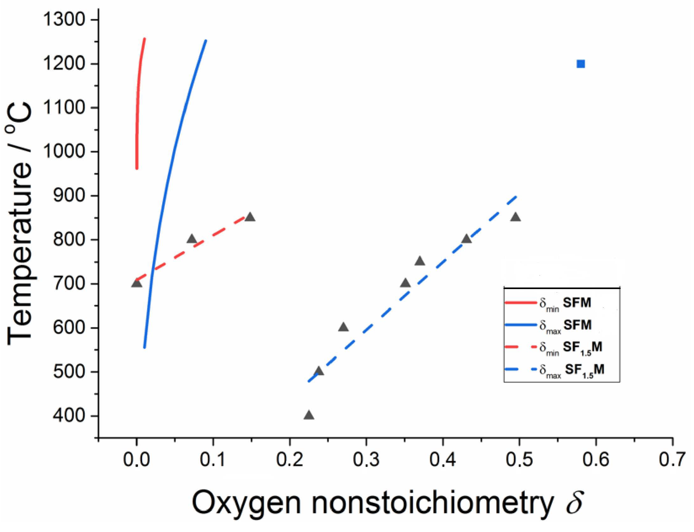
Figure 2.
Schematic representation of the temperature dependence of conductivity in SF1+xM ceramics.
Figure 2.
Schematic representation of the temperature dependence of conductivity in SF1+xM ceramics.
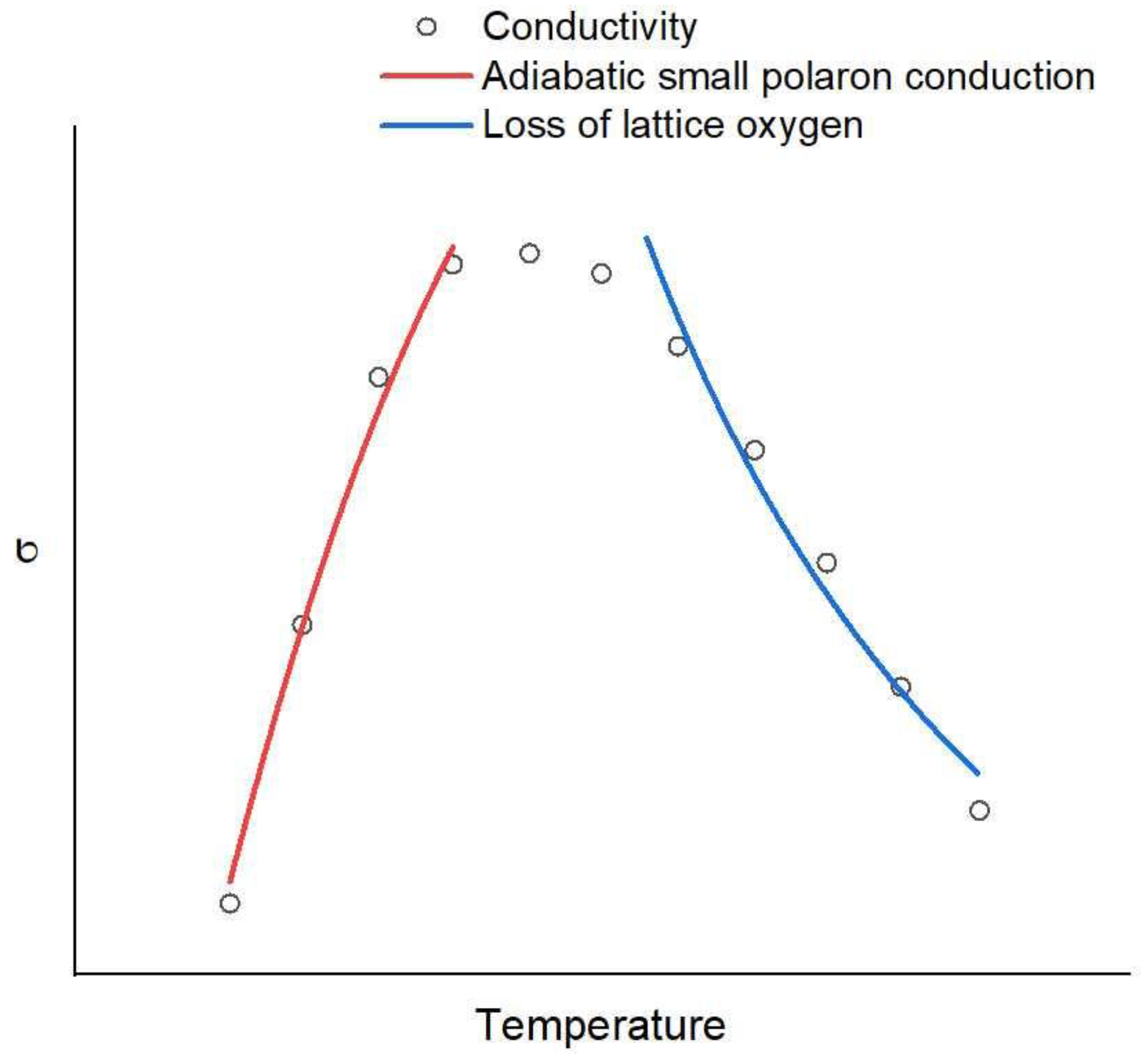
Figure 3.
EIS spectrum representing the resistances of a SOFC.
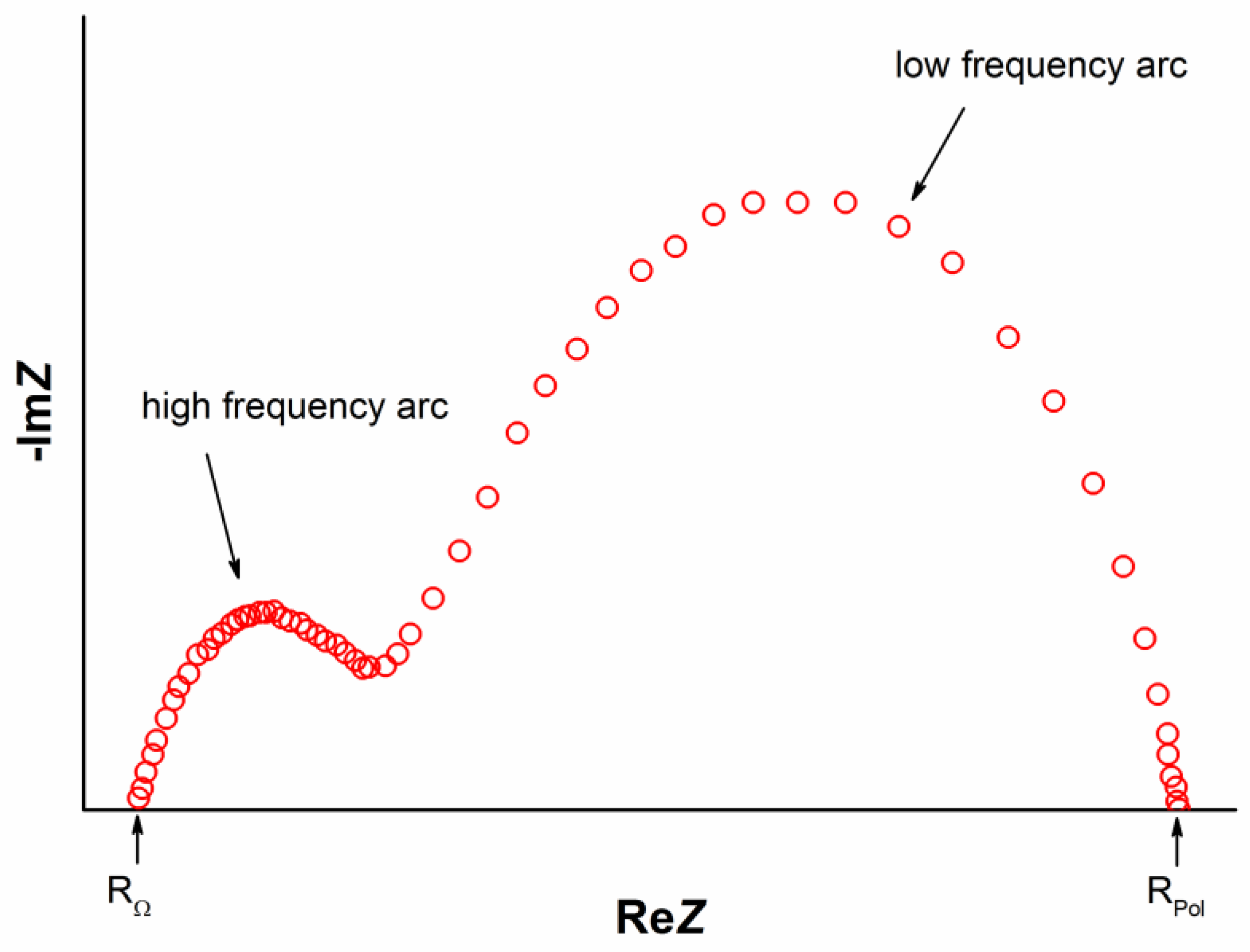

| Bond Configuration | Ef(VO), eV | |||
|---|---|---|---|---|
| x = 0 | x = 0.5 | x = 1.0 | x = 1.5 | |
| Fe-O-Mo | 2.95 | 2.89 | 2.58 | |
| Fe-O-Fe | 2.30 | 2.19 | ||
| Co-O-Mo | 2.78 | 2.41 | 2.2 | |
| Co-O-Co | 1.80 | 1.37 | ||
| Fe-O-Co | 2.08 | 1.74 | ||
Table 2.
Activation energy of the adiabatic polaron hopping model of double perovskites measured under environmental conditions.
Table 2.
Activation energy of the adiabatic polaron hopping model of double perovskites measured under environmental conditions.
| Compound | Temperature Range, °C | Ea, eV | Ref. |
|---|---|---|---|
| LSCF | 100–500 | 0.10 | [91] |
| BSCF | 45–470 | 0.365 | [92] |
| SMgM | 450–850 | 0.279 | [93] |
| S1.8Sm0.2MgM | 0.195 | ||
| S1.6Sm0.4MgM | 0.113 | ||
| S1.4Sm0.6MgM | 0.080 | ||
| S1.2Sm0.8MgM | 0.087 | ||
| SFO | 400–500 | 0.204 | [25] |
| SF1.9M | 400–600 | 0.221 | |
| SF1.8M | 400–600 | 0.164 | |
| SF1.6M | 410–700 | 0.162 | |
| SF1.5M | 400–750 | 0.156 | |
| SF1.5M | 40–440 | 0.236 | [39] |
| SF1.0C0.5M | 40–530 | 0.193 | |
| SF0.5C1.5M | 40–530 | 0.137 | |
| SF1.5M | 300–450 | 0.067 | [45] |
Table 3.
Parameters of metallic conductivity of SF1+xM measured under reducing conditions.
| Compound | ρ(0), mΩ cm | ν | Rν, µΩ cm T-ν | Ref. |
|---|---|---|---|---|
| SF1.33M | 18.8 | 1.54 | 1.482 | [34] |
| SFM | 1.85 | 2.07 | 0.0013 | [93] |
| SFM | 3.01 | 1.75 | 0.014 | [94] |
Table 4.
Activation energy of the adiabatic polaron model of SF1.5M-based ceramics under reducing conditions.
Table 4.
Activation energy of the adiabatic polaron model of SF1.5M-based ceramics under reducing conditions.
| Compound | Temperature Range, °C | Ea, eV | Ref. |
|---|---|---|---|
| SF1.5M | 475–800 | 0.167 | [29] |
| SF1.5M | 475–800 | 0.292 | [35] |
| S1.9F1.4Ni0.1M | 400–800 | 0.240 | |
| SF1.5M | 200–800 | 0.225 | [56] |
| SF1.5M | 400–750 | 0.15 | [32] |
| SF1.5M (SF1.4N0.1M) | 300–800 | 0.115 (0.1) | [30] |
| SFM0.8N0.2 | 600–800 | 0.281 | [96] |
| SFM0.65Ni0.35 | 250–700 | 0.05 | [97] |
Table 5.
Performance of S2F1+xM1−x-based SOFCs operated with hydrogen fuel.
| Configuration Anode-Electrolyte-Cathode | del, µm | T, °C | Pmax, W/cm2 | Ref. |
|---|---|---|---|---|
| SFM/LSGM/SDC/SmBC2 | 300 | 850 | 0.831 | [60] |
| 800 | 0.584 | |||
| 750 | 0,412 | |||
| SFM/LSGM/SDC/SmBC2 | 300 | 850 | 0.735 1 | [60] |
| 800 | 0.476 1 | |||
| 750 | 0.183 1 | |||
| BFM/LSGM/SDC/SmBC2 | 300 | 850 | 0.561 | [60] |
| 800 | 0.338 | |||
| 750 | 0.206 | |||
| CaFM/LSGM/SDC/SmBC2 | 300 | 850 | 0.186 | [60] |
| SFM/LSGM/BSCF | 300 | 850 | 0.864 | [61] |
| 800 | 0.603 | |||
| 750 | 0.436 | |||
| SFN0.8M0.2/LSGM/PBCO | 200 | 800 | 0.520 | [96] |
| 700 | 0.375 | |||
| 600 | 0.130 | |||
| 550 | 0.061 | |||
| SF1.33M/LGSM/LSCF | 300 | 800 | 0.547 | [34] |
| 750 | 0.392 | |||
| 700 | 0.268 | |||
| SF1.33M/LGSM/LSCF | 300 | 800 | 0.472 1 | [34] |
| SFM/LSGM/BSCF | 300 | 850 | 0.864 | [61] |
| 800 | 0.603 | |||
| 750 | 0.436 | |||
| SF1.33M/LGSM/LSCF | 300 | 800 | 0.472 1 | [34] |
| SF1.33M/LGSM/LSCF | 265 | 850 | 0.532 | [98] |
| 800 | 0.340 | |||
| 750 | 0.200 | |||
| SF1.33M/LGSM/LSCF SF1.5M/LGSM/LSCF | NA | 800 | 0.588 0.474 | [29] |
| SF1.33Mo0.66/LGSM/LSCF SF1.5M/LGSM/LSCF | NA | 800 | 0.473 1 0.432 1 | [29] |
| Ni-SF1.5M/LGSM/LSCF | 300 | 800 | 1134 | [99] |
| SF1.5M-GDC/CeGdO/BCFN | 50 | 700 | 0.188 | [100] |
| 650 | 0.100 | |||
| 600 | 0.039 | |||
| S1.9F1.4Ni0.1M/LSGM/CLO/LSCF | NA | 850 | 1.160 | [35] |
| 800 | 0.968 | |||
| 750 | 0.730 | |||
| SF1.5M-GDC/GDC/GDC-LSCF | 35 | 700 | 0.22 | [95] |
| 600 | 0.14 | |||
| LSMn/YSZ-S2FM/YSZ/YSZ-LSFSc | 24 | 800 | 0.462 | [52] |
| 750 | 0.324 | |||
| SF1.4M/LSGM/BSCF SF1.5M/LSGM/BSCF SF1.6M/LSGM/BSCF | 300 | 800 | 0.514 0.508 0.482 | [22] |
| SF1.4M/LSGM/BSCF SF1.5M/LSGM/BSCF SF1.6M/LSGM/BSCF | 300 | 750 | 0.387 0.385 0.380 | [22] |
| SF1.3Co0.3M0.4/LSGM/LSCF | 170 | 850 | 1.09 | [74] |
| 800 | 0.81 | |||
| 750 | 0.50 | |||
| 700 | 0.30 | |||
| SF1.3Co0.3M0.4/LSGM/LSCF | 170 | 850 | 0.981 2 | [74] |
| 800 | 0.808 2 | |||
| 750 | 0.604 2 | |||
| Ni-LDC/LDC/LSGM/SF1.5M | 300 | 850 | 0.613 | [101] |
| 800 | 0.468 | |||
| 750 | 0.349 | |||
| Ni-LDC/LDC/LSGM/SF1.5M | 265 | 850 | 0.613 | [98] |
| 800 | 0.468 | |||
| 750 | 0.349 | |||
| Ni-YSZ/YSZ/SDC/S1.8B0.2F1.5M | 700 | 800 | 1.63 | [37] |
| 750 | 1.3 | |||
| 700 | 0.87 | |||
| 650 | 0.41 | |||
| Ni-YSZ/YSZ/SDC/SF1.5Mo0.4N0.1 | 400 | 800 | 1.102 | [45] |
| 750 | 0.920 | |||
| 700 | 0.671 | |||
| 650 | 0.421 | |||
| Ni-YSZ/YSZ/SDC/S1.8B0.2F1.5M Ni-YSZ/YSZ/SDC/S1.6B0.4F1.5M Ni-YSZ/YSZ/SDC/S1.4B0.6F1.5M | 400 | 800 | 1.06 1.26 0.94 | [44] |
| Ni-YSZ/YSZ/SDC/SF1.4Ni0.1M | 10 | 800 | 1.77 | [40] |
| 750 | 1.21 | |||
| 700 | 0.79 | |||
| 650 | 0.33 | |||
| Ni-YSZ/LSGM/SDC/SF1.5M Ni-YSZ/LSGM/SDC/SF1.45Sc0.05M | 400 | 800 | 0.91 1.23 | [42] |
| Ni-ScSZ/ScSZ/SDC/SF1.4Co0.1M Ni-ScSZ/ScSZ/SDC/S1.95F1.4Co0.1M Ni-ScSZ/ScSZ/SDC/S1.9F1.4Co0.1M | 11 | 800 | 0.88 1.16 0.96 | [73] |
| SF1.5M/LSGM/SF1.5M | 265 | 900 | 0.835 | [12] |
| SF1.5M/LSGM/SF1.5M | 265 | 900 | 0.835 | [98] |
| SF1.5M/LSGM/SF1.5M | 243 | 800 | 0.531 | [30] |
| 750 | 0.365 | |||
| 700 | 0.244 | |||
| 650 | 0.124 | |||
| SF1.4N0.1M/LSGM/SF1.5M | 236 | 800 | 0.374 | [30] |
| 750 | 0.228 | |||
| 700 | 0.156 | |||
| 650 | 0.092 | |||
| S1.4Ca0.6F1.5M/LSGM/S1.4Ca0.6F1.5M | 35 | 800 | 1.050 | [38] |
| 750 | 0.880 | |||
| 700 | 0.660 | |||
| 600 | 0.410 | |||
| SF1.4Ni0.1M/LSGM/SF1.4Ni0.1Mo0.5 | 310 | 800 | 0.530 3 | [41] |
| 750 | 0.380 | |||
| 700 | 0.258 | |||
| 650 | 0.164 | |||
| SF1.5M/LSGM/SF1.5M0.2Sn0.3 | 400 | 800 | 0.618 | [43] |
| 750 | 0.431 | |||
| 700 | 0.262 |
1 H2S/H2, 2 syngas, 3 anode decomposes.
Table 6.
Performance of SF1+xM-based SOFCs operated with hydrocarbons.
| Configuration Anode-Electrolyte-Cathode | Fuel | del, µm | T, °C | Pmax, W/cm2 | Ref. |
|---|---|---|---|---|---|
| SFM/LSGM/BSCF | CH4 | 300 | 850 | 0.605 | [61] |
| 800 | 0.429 | ||||
| SF1.33M/LGSM/LSCF | CH4 | 300 | 800 | 0.13 | [34] |
| SF1.33M/LGSM/LSCF SF1.5M/LGSM/LSCF | CH4 | NA | 800 | 0.079 0.041 | [29] |
| SF1.5M/LSGM/SF1.5M | CH4 | 265 | 900 | 0.23 | [99] |
| SF1.5M/LSGM/SF1.5M | CH4 | 400 | 900 | 0.250 | [31] |
| 850 | 0.125 | ||||
| Ni-SF1.5M/LGSM/LSCF | CH4 | 300 | 800 | 0.663 | [99] |
| SF1.3Co0.3M/LSGM/LSCF | CH4 | 170 | 850 | 0.290 | [74] |
| 750 | 0.151 | ||||
| 700 | 0.057 | ||||
| SFM-YSZ/YSZ/YSZ-LSFSc | C3H8 | 24 | 800 | 0.331 | [52] |
| 750 | 0.173 | ||||
| SF1.4M/LSGM/BSCF SF1.5M/LSGM/BSCF SF1.6M/LSGM/BSCF | CH3OH | 300 | 800 | 0.415 0.395 0.382 | [22] |
| SF1.4M/LSGM/BSCF SF1.5M/LSGM/BSCF SF1.6M/LSGM/BSCF | CH3OH | 300 | 750 | 0.341 0.297 0.205 | [22] |
Table 7.
Polarization resistances of operational SOCFs consisting of SF1+xM ceramics.
| Configuration Anode-Electrolyte-Cathode | T, °C | Rp, Ω cm2 | Ref. |
|---|---|---|---|
| SFM/LSGM/SDC/SmBC2 | 850 | 0.284 | [60] |
| 800 | 0.327 | ||
| 750 | 0.583 | ||
| SFM-YSZ/YSZ/YSZ-LSFSc0.1O | 750 | 0.52 2.11 1 | [52] |
| SFM-YSZ/YSZ/YSZ-LSFSc0.1 SF1.2M-YSZ/YSZ/YSZ-LSFSc0.1 SF1.35M-YSZ/YSZ/YSZ-LSFSc0.1 SF1.5M-YSZ/YSZ/YSZ-LSFSc0.1 | 800 | 0.152 0.176 0.193 0.235 | [52] |
| SF1.33M/LGSM/LSCF | 800 | ~0.2 | [34] |
| 750 | 0.26 | ||
| 700 | 0.45 | ||
| SF1.5M/LGSM/LSCF | 850 | 0.40 | [98] |
| 800 | 0.76 | ||
| 750 | 1.73 | ||
| SF1.3Co0.3M/LSGM/LSCF | 850 | 0.152 | [74] |
| 800 | 0.223 | ||
| 750 | 0.369 | ||
| 700 | 0.575 | ||
| SF1.3Co0.3M/LSGM/LSCF | 850 | 0.442 2 | [74] |
| 800 | 0.842 2 | ||
| 750 | 1.979 2 | ||
| Ni-LDC/LDC/LGSM/SF1.33M | 800 | 0.32 | [101] |
| Ni-YSZ/YSZ/SDC/SF1.5M | 750 | 0.42 | [37] |
| 700 | 0.92 | ||
| Ni-YSZ/YSZ/SDC/SF1.5M0.4N0.1 | 800 | 0.168 | [45] |
| SDC-SF1.65M/LGSM/SF1.5M | 750 | 0.11 0.27 | [111] |
| S1.4C0.6F1.5M/LSGM/S1.4C0.6F1.5M | 800 | 0.155 | [38] |
| 750 | 0.179 | ||
| 700 | 0.220 | ||
| 650 | 0.359 | ||
| SF1.2Co0.3M/LSGM/SF1.2Co0.3M | 850 | 0.152 | [74] |
| 800 | 0.223 | ||
| 750 | 0.369 | ||
| 700 | 0.575 | ||
| SF1.5M/LSGM/SF1.5M0.2Sn0.3 | 800 | 0.22 | [43] |
| 750 | 0.35 | ||
| 700 | 0.71 |
1 C3H8, 2 CH4.
Publisher’s Note: MDPI stays neutral with regard to jurisdictional claims in published maps and institutional affiliations. |
© 2022 by the authors. Licensee MDPI, Basel, Switzerland. This article is an open access article distributed under the terms and conditions of the Creative Commons Attribution (CC BY) license (https://creativecommons.org/licenses/by/4.0/).
Share and Cite
MDPI and ACS Style
Suchaneck, G.; Artiukh, E. Nonstoichiometric Strontium Ferromolybdate as an Electrode Material for Solid Oxide Fuel Cells. Inorganics 2022, 10, 230. https://doi.org/10.3390/inorganics10120230
AMA Style
Suchaneck G, Artiukh E. Nonstoichiometric Strontium Ferromolybdate as an Electrode Material for Solid Oxide Fuel Cells. Inorganics. 2022; 10(12):230. https://doi.org/10.3390/inorganics10120230
Chicago/Turabian StyleSuchaneck, Gunnar, and Evgenii Artiukh. 2022. "Nonstoichiometric Strontium Ferromolybdate as an Electrode Material for Solid Oxide Fuel Cells" Inorganics 10, no. 12: 230. https://doi.org/10.3390/inorganics10120230
Note that from the first issue of 2016, this journal uses article numbers instead of page numbers. See further details here.