Article

Nickel Oxide-Incorporated Polyaniline Nanocomposites as an Efficient Electrode Material for Supercapacitor Application

1
Central Department of Chemistry, Tribhuvan University, Kathmandu 44618, Nepal
2
Department of Nano Convergence Engineering, Jeonbuk National University, Jeonju 561756, Korea
*
Authors to whom correspondence should be addressed.
Inorganics 2022, 10(6), 86; https://doi.org/10.3390/inorganics10060086
Submission received: 1 June 2022 / Revised: 10 June 2022 / Accepted: 17 June 2022 / Published: 19 June 2022

Abstract

:
This work reports the facile, controlled, and low-cost synthesis of a nickel oxide and polyaniline (PANI) nanocomposites-based electrode material for supercapacitor application. PANI-NiO nanocomposites with varying concentrations of NiO were synthesized via in-situ chemical oxidative polymerization of aniline. The XRD and FTIR support the interaction of PANI with NiO and the successful formation of the PANI-NiO-x nanocomposite. The SEM analysis showed that the NiO and PANI were mixed homogenously, in which the NiO nanomaterial was incorporated in porous PANI globular nanostructures. The multiple phases of the nanocomposite electrode material enhance the overall performance of the energy-storage behavior of the supercapacitor that was tested in 1 M H2SO4 using cyclic voltammetry (CV), galvanostatic charge-discharge (GCD), and electrochemical impedance spectroscopy (EIS). Among the different nanocomposites, PANI-NiO-3 exhibit the specific capacitance of a 623 F g−1 at 1 A g−1 current density. Furthermore, the PANI-NiO-3 electrode retained 89.4% of its initial capacitance after 5000 cycles of GCD at a 20 A g−1 current density, indicating its significant cyclic stability. Such results suggest that PANI-NiO nanocomposite could be proposed as an appropriate electrode material for supercapacitor applications.

1. Introduction

Due to the energy crisis, global warming, and less availability of non-renewable energy sources, researchers focus on providing low-cost, high-power, and environment-friendly energy sources [1,2]. Over the past few decades, intense research has been conducted to develop efficient energy-storage devices. Fuel cells, supercapacitors, and batteries are promising and sustainable energy-storage devices that have attracted huge research interest due to their high energy and power densities, long life cycles, and eco-friendliness [3,4]. Supercapacitors are among the most promising materials due to their long cycle life, moderate energy density, excellent reversibility, high power density, and ease of fabrication [5,6,7].
Supercapacitors can be divided into electric double-layer capacitors (EDLCs), pseudocapacitors, and hybrid supercapacitors (battery-type supercapacitors). EDLCs store energy physically by the adsorption or desorption of ions at the electrode/electrolyte interface and includes mainly activated carbon, graphene, and carbon nanotubes [8,9,10]. The hybrid-type supercapacitors utilize faradic and EDLC-type mechanisms to store charge [11,12]. Pseudocapacitors store energy by reversible fast-redox reactions from transitional metal oxides (TMOs), transitional metal hydroxides (TMHs), transitional metal sulfides (TMSs), transitional metal phosphides (TMPs), and conductive polymers [1,2,13,14,15]. The pseudocapacitor has attracted researchers in recent years due to its high energy density, power density, and significant cycle life [16,17]. Among various materials, TMOs are promising electrode materials for supercapacitors. In the last few decades, ruthenium oxide was considered the best electrode material for pseudocapacitor material, however its cost, abundance, and limited potential window restrict its application [16,18]. Researchers focused on other TMOs-based electrode materials with reversible faradic reactions and higher capacitance [15,19]. They possess large theoretical capacitance, simple preparation methods, and various oxidation states. However, TMOs alone cannot restrain their suitability as supercapacitor electrodes due to insufficient structural stability for a high current density and a long cycle life [19,20].
Conducting polymers (CPs) are also well-suited for supercapacitor applications due to their excellent optical and electronic properties [21]. PANI is a promising flexible electrode material for supercapacitor applications among various conducting polymers due to its low cost, fast kinetics, good electrical conductivity, and environmental stability [22,23]. The long-chain conjugated structure of polyaniline (PANI), along with the interconvertible benzenoid ring and quinoid structure by electron transfer process, is responsible for the high specific capacitance of PANI [24,25]. PANI can be synthesized from its aniline monomer either by chemical or electrochemical methods. However, PANI possesses inferior mechanical stability because of shrinking and swelling during the charge–discharge process, which results in a poor life cycle [21,26]. Therefore, the design and manufacture of metal-oxide nanocomposite with the electro-conductive polymer can provide additional pseudocapacitance and resolve the issues mentioned above.
Among various TMOs, NiO is a significant metal oxide with a cubic lattice structure; it is insulating in nature with very low conductivity at room temperature and is widely used in diverse fields, such as catalysis, supercapacitor, battery cathode, gas sensors, and electrochromic and magnetic materials [16,27,28]. The NiO nanoparticle is a p-type semiconductor with a bandgap of 3.51 eV [29]. Various methods have been reported for the synthesis of NiO nanoparticles, such as microemulsion [30], sol-gel [31], solvothermal [32], precipitation [33] and microwave methods [34], etc. NiO possesses excellent features, such as anodic electrochromism, better durability, electrochemical stability, large-spin optical density, and different manufacturing possibilities [33,35].
Qi et al. synthesized PANI-NiO composites by in-situ polymerization in the presence of HCl as a dopant [36]. Sambharkar et al. prepared NiO nanoparticles and incorporated them into a polyaniline matrix during the in-situ chemical oxidative polymerization of aniline with different molar ratios of aniline: NiO (12:1, 6:1, and 3:1) at 5 °C using (NH4)2S2O8 as an oxidant in an aqueous solution of sodium dodecyl benzene sulfonic acid as a surfactant and dopant under an N2 atmosphere [37]. Wu et al. prepared a novel nano-nickel oxide-coated graphene/polyaniline composite and found its specific capacitance value to be about 1409 F g−1 [38]. Singu et al. synthesized a polyaniline nickel-oxide nanocomposite by in-situ oxidative polymerization and used it for supercapacitor applications. Such a nanocomposite possesses high specific capacitance up to 514 F g−1 at a scan rate of 1 mV s−1 [39].
In this study, a PANI-NiO nanocomposite was prepared by doping nickel oxide in polyaniline by the in-situ oxidative polymerization of aniline and it was used as an active material to prepare electrodes for high-performance supercapacitors. The main objective of this research is to study the specific capacitance and the chemical stability of nickel- oxide-doped polyaniline nanocomposites i.e., PANI-NiO-x. In brief, the as-prepared PANI-NiO-3 has a high capacitance of 623 F g−1 at a current density of 1 A g−1 and a good cycle life with a capacitance retention of over 92.5% after 5000 cycles. Moreover, it can retain 55.9% specific capacitance (Csp) of its initial capacitance value even at 10 A g−1, showing its efficient ability as an electrode material with a higher electrochemical performance.

2. Experimental Section

Materials and characterization techniques are presented in Sections S1.1 and S1.2 of the supplementary file.

2.1. Synthesis of Nickel Hydroxide

A total of 5.9 g of nickel chloride hexahydrate (NiCl3.6H2O) and 0.58 g of SDS were dissolved in 200 mL of double-distilled water and then the solution was stirred for 1 h. Subsequently, 20 mL of 30% ammonia solution was added to the above solution under constant stirring. The resulting mixture was refluxed for 4 h and allowed to reach room temperature. The green precipitation of nickel hydroxide was observed which was separated under vacuum filtration with the help of Whatman filter paper (No. 2) and washed with distilled water repeatedly. The resulting powder was dried at 75 °C for 12 h.

2.2. Conversion of Nickel Hydroxide into Nickel Oxide (NiO)

The previously synthesized powder of nickel hydroxide was calcined in a muffle furnace in the presence of air at 500 °C for 3 h. Hence, the obtained NiO was used in the subsequent steps.

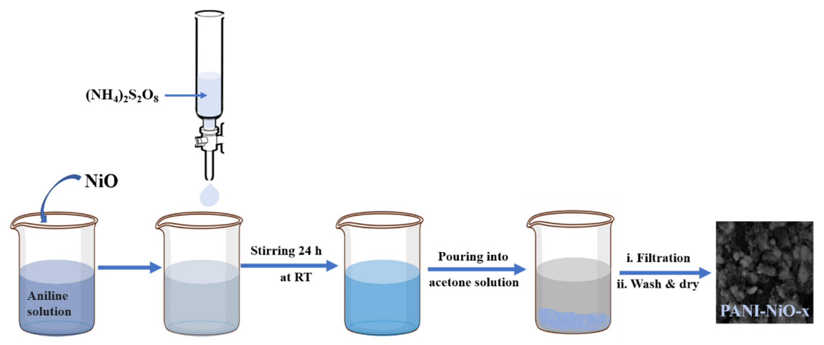
2.3. Synthesis of Polyaniline—Nickel Oxide Nanocomposite (PANI-NiO Nanocomposite)

Different proportions of the NiO (0.1, 0.2, 0.3, 0.5 g) were added to 50 mL of 0.22 M aniline in 1 M H2SO4 solution with constant stirring. To the mixture, 50 mL of 0.24 M ammonium persulfate (APS) solution was added from the burette dropwise (3 drops per second). The reaction mixture was stirred for 24 h at room temperature. After completion of the reaction, the mixture was poured into 250 mL of acetone to obtain the precipitation of the PANI-NiO. The precipitate was collected in Whatman filter paper and washed with distilled water and acetone several times until the filtrate became colorless. The resulting powder sample was dried in air for 12 h and then at 75 °C for 24 h in the oven. Similarly, the PANI was synthesized without adding the NiO. The dried salt samples were kept in an airtight borosil glass bottle for further purposes.

2.4. Electrochemical Measurements

Various electrochemical properties, such as cyclic voltammetry (CV), charge–discharge cycle (GCD), and electrochemical impedance spectroscopy (EIS) of different samples were recorded by Hokuto Denko Ha-151 Potentiostat/Galvanostat, Japan. The electrochemical measurements were performed using a three-electrode system with a saturated calomel electrode as a reference electrode, as-prepared material as a working electrode, and platinum as a counter electrode in 1 M H2SO4 solutions as an electrolyte. The CV tests were obtained for various samples of composite electrodes at a scan rate of 10 m Vs−1 in the potential range of −0.2 V to 1 V. The GCD tests were performed at a current density of 2 A g−1 in the potential window ranging from 0.0 V to 1.0 V in the 3-electrode system. The different working electrodes (of different samples) were prepared by coating the active materials onto a nickel mesh of 0.5 cm × 0.5 cm dimensions. A few drops of NMP were poured into the mixture of active materials PVDF binder, and carbon black in the ratio 80:10:10 wt%, then grounded to produce a slurry in a mortar. The slurry was sonicated to make it homogeneous, drop-cast onto nickel mess and pressed hard on both sides; Cu-tape was used for the electrical connection. Then, it was allowed to dry in the oven for 18 h at 70 °C. The specific capacitance values from the GCD curves were calculated using Equation (1) [40]:
S p e c i f i c   C a p a c i t a n c e   ( C s   ) = 2 I × V   d t m × ( V ) 2
where I is the current (A), V   d t is the integrated area under the discharge curve, m is the mass of the active electrode materials (g), S is the area of the working electrode (in our case, we fixed the area as 1 cm2),   and   V is the working potential window (V). The coulombic efficiency was calculated by using Equation (2) [41]:
C o u l o m b i c   e f f i c i e n c y   ( η ) = t d t c × 100 %
where, t d and t c are the discharge and charge times in second (s), respectively.

3. Results and Discussion

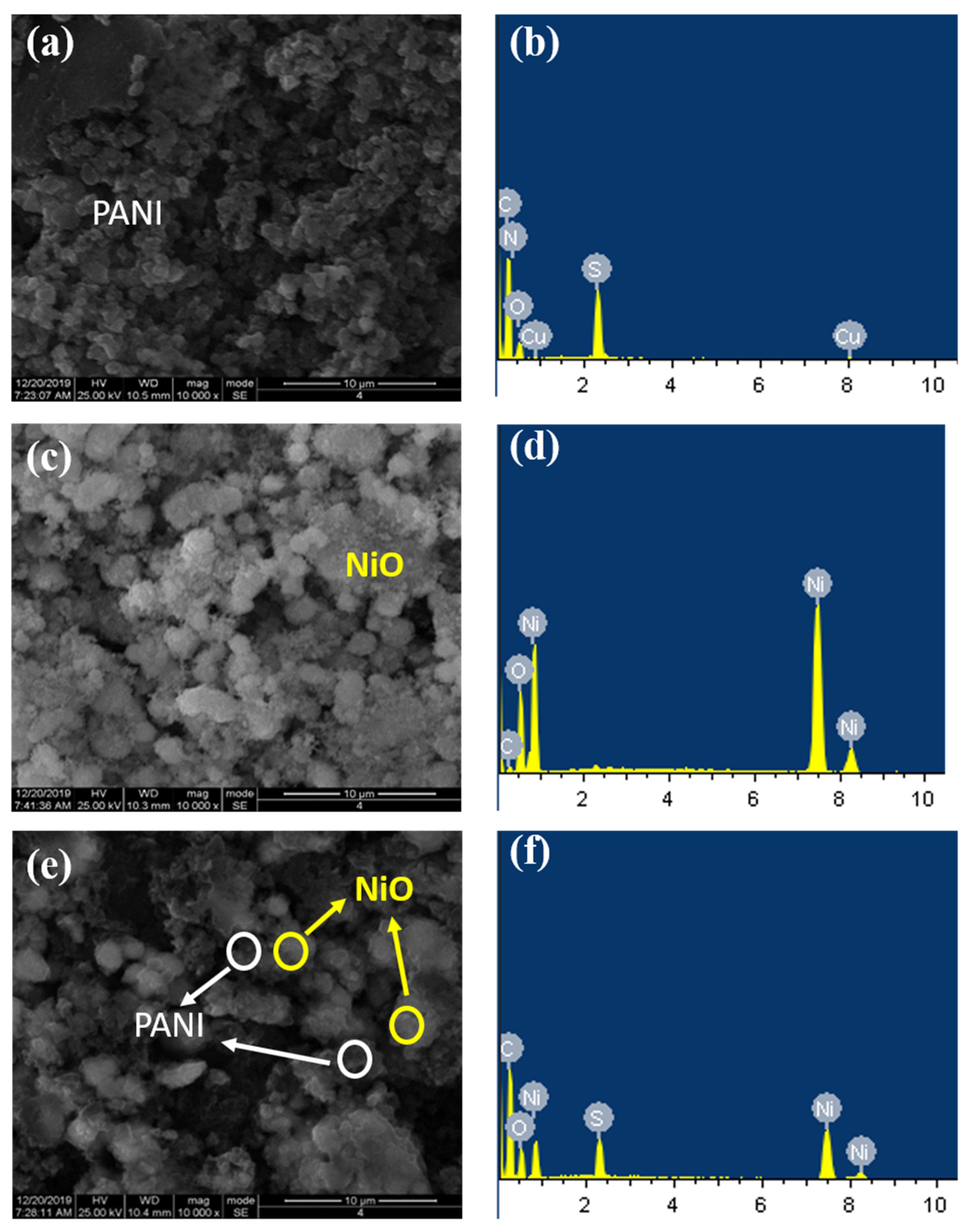
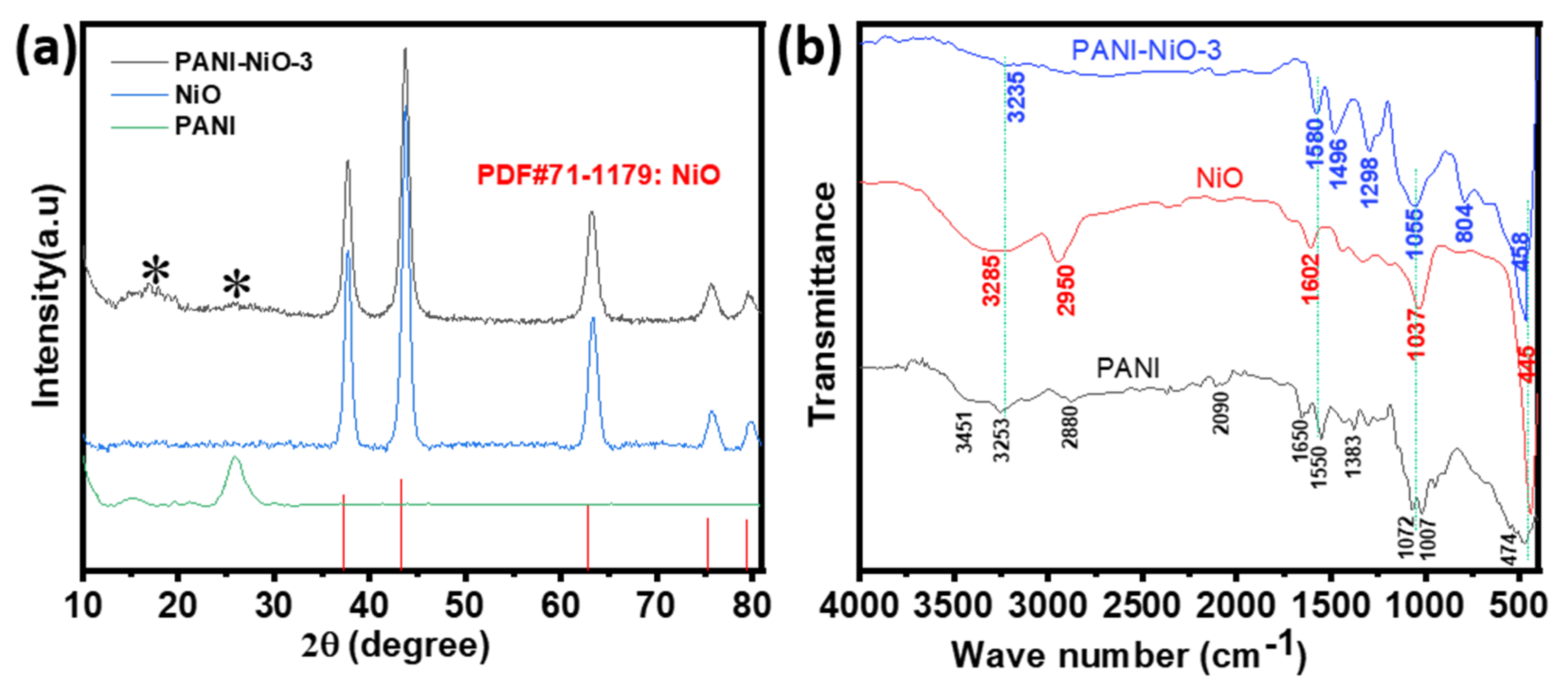
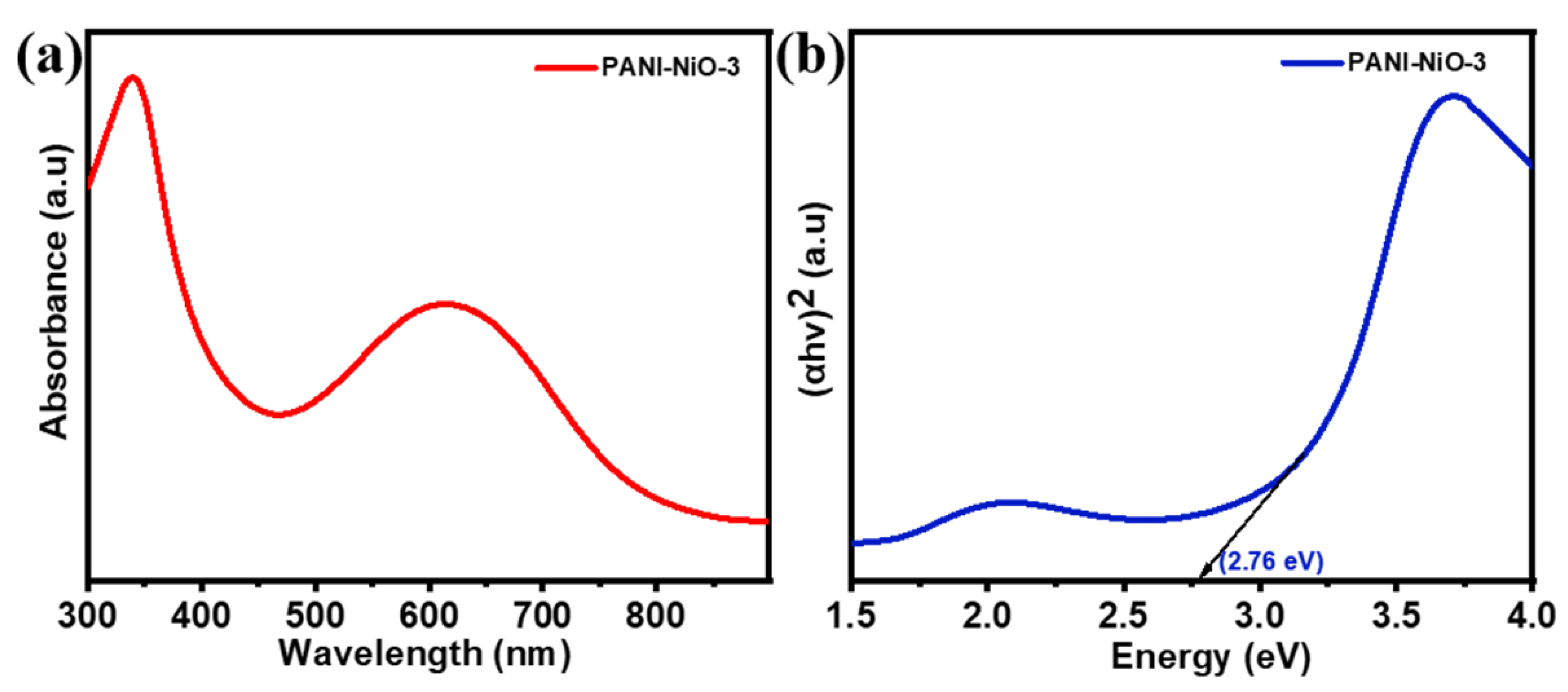
3.1. Synthesis, Morphology, and Structural Characterization

A simple chemical oxidation technique is used to synthesize PANI, and NiO powder is prepared from nickel hydroxide by using the calcination process. The electrode material PANI-NiO nanocomposite was prepared by a chemical treatment method, followed by a co-precipitation method. The schematic representation of the facile preparation of the PANI-NiO-x nanocomposites is shown in Figure 1. The surface morphology and interaction between PANI and NiO were examined by using a scanning electron microscopy (SEM) analysis, as shown in Figure 2. The SEM image of pure PANI and NiO only is shown in Figure 2a,c with the related energy dispersive X-ray analysis (EDX) in Figure 2b,d, respectively. Figure 2a shows the irregular nanostructures of PANI and Figure 2c shows that the NiO is present in spherical form. The SEM images of the PANI-NiO-3 with the corresponding EDX images are presented in Figure 2e,f, respectively. Similarly, the SEM images and related EDX images of PANI-NiO-1, PANI-NiO-2, PANI-NiO-4, and PANI-NiO-5 are shown in Figure S1. The SEM images of the PANI-NiO-x nanocomposites show that the NiO nanospheres were incorporated into PANI during the in-situ oxidative polymerization of aniline into polyaniline.
In redox supercapacitors, fiber morphology and porous structure are desired features of electrode materials as they can provide a large surface area and enable effective and rapid access to the electrolyte, enabling the provision of high-specific capacitance and a fast charge/discharge rate [42]. Figure S1a,c,e,g in Supplementary Materials shows that the uniform morphology of the PANI-NiO nanocomposites is changed to extended interfaces with a much finer internal structure due to the agglomerating tendency of nanoparticles, as well as the formation of clusters or agglomerates which decrease the interfacial interaction between the PANI matrix and NiO, resulting in the decrease-specific capacitance values [43,44].
The EDX pattern of PANI in Figure 2b consists of strong peaks corresponding to carbon, oxygen, and nitrogen which confirms PANI formation. The EDX pattern of NiO in Figure 2d shows strong peaks corresponding to nickel and oxygen which confirms the formation of NiO. The EDX pattern of the PANI-NiO-x nanocomposites is shown in Figure 2f and Figure S1b,d,f,h revealing the presence of NiO and PANI, which indicate the successful formation of PANI-NiO-x nanocomposite. The nitrogen peak is absent in the EDX pattern of nanocomposites which confirms that NiO was doped in PANI. Some impurities at 1.9 KeV are observed due to sulfur. The presence of the element sulfur indicates the presence of the SO3H group, which might have come from a sodium lauryl sulfate (SLS) surfactant/oxidant.
The XRD and FTIR of the PANI, NiO, and PANI-NiO-3 is presented in the Figure 3. XRD patterns of all samples were characterized in the range of 2θ throughout 10–80° to examine the crystal structure and composition of the as-prepared electrode materials. The XRD patterns of PANI-NiO-1, PANI-NiO-2, PANI-NiO-4, and PANI-NiO-5 nanocomposites are shown in Figure S2a.
The XRD pattern and crystalline structure of NiO suggest the successful preparation of the NiO. The XRD spectra of NiO show the diffraction peaks centered at about 2θ values of 37.3, 43.3, 62.8, 75.3, and 79.3°, corresponding to lattice plane (111), (200), (220), (311), and (222), related to the cubic nickel oxide, respectively. All the peaks are in good agreement with PDF card no. 71-1179 of NiO [45]. The XRD spectra of the PANI-NiO-3 composite that are shown in Figure 3a exhibited a diffraction peak that is constituted by a mixture of PANI and NiO peaks. In the PANI-NiO-3 composite, there are some reduced peaks indicated by asterisks at around the 2θ (~25.91° and ~16.9°), showing the presence of PANI with the respective peaks of NiO, according to PDF card no. 71-1179 of NiO. PANI diffraction peak intensities are reduced in the nanocomposite, implying that PANI is present in the form of nanocomposites with NiO. Observing the characteristic peaks of pristine NiO in composite and broadening and weakening the intensity of NiO peaks suggests the reduction in the crystallinity of NiO in the nanocomposite. All these observations revealed that NiO was homogeneously doped with PANI, and PANI-NiO-x nanocomposites were successfully formed. The reduction in crystallinity of NiO and improved amorphous phase of PANI are certainly beneficial for electrochemical performance by improving the surface area, increasing the number of redox active sites, and shortening the charge transport path for the electrochemical reactions [37].
The Fourier transform infrared (FTIR) spectra of the as-prepared samples are shown in the range of 4000–400 cm−1 (Figure 3b and Figure S3). The FTIR spectrum of PANI shows a characteristic absorption band at 1660 cm−1 due to the C=N stretching vibration of the quinoid ring. The bands at 1560 and 1431 cm−1 are characteristics of the C=C stretching vibration of the quinoid ring and benzenoid ring, respectively. The bands at 3253–3451 cm−1 are attributed to the N–H stretching of aromatic amine, whereas the band at about 788 cm−1 shows a N–H wag of the secondary amines (one hydrogen and two aromatic groups). The bands at about 1227, 1309, and 1383 cm−1 are assigned to the out-of-plane bending of C–H [46]. The band at 1007 cm−1 is assigned to the in-plane bending vibration of aromatic C–H, which was formed during the protonation of the PANI chain. The band at 1072 cm−1 is assigned to be a quinoid ring-NH+-benzenoid ring (Q=NH+–B) stretching vibration, a characteristic band for emeraldine salt, attributed to the doping of PANI with H+ [25,47]. The above bands indicate the formation of the conductive emeraldine-salt form of PANI and are presented in Figure S3a. The FTIR spectrum of the NiO nanoparticles in the range of 4000–400 cm−1 is shown in Figure S3b. The FTIR spectrum of the NiO nanoparticles shows the characteristic absorption band of Ni–O stretching vibration at 445 cm−1. The peaks at 3285, 2950, 1602, and 1037 cm−1 are attributed to the stretching vibration of the different groups on the NiO [48].
The comparative FTIR spectra of the PANI-NiO-3, PANI, and NiO are shown in Figure 3b. The peaks at the PANI-NiO-3 are slightly positively shifted due to the formation of the nanocomposite and changes in the morphology and size of the particles. Similar absorption bands of PANI and NiO have been observed in PANI-NiO-x nanocomposites with a slight shift. Such a slight shift is the result of the interaction between PANI chains and NiO. The peak corresponding to Q=NH+–B is shifted from 1072 cm−1 to lower wavenumber 1055 cm−1 and the peak corresponding to –NH stretching at 3253 cm−1 broadens due to NiO doping. The N–H stretching peak at 3253 cm−1 is shifted to a lower intensity and is broad, revealing a strong interaction of NiO and PANI by the formation of hydrogen bonding between the N–H proton of PANI and the oxygen atom of NiO [49]. The characteristic peak of Ni–O vibration at 445 cm−1 is shifted to 485 cm−1, which reveals a strong interaction between NiO and PANI at the interface of the PANI polymer-chain matrix. Additionally, the FTIR spectra of PANI-NiO-1, PANI-NiO-2, PANI-NiO-4, and PANI-NiO-5 are shown in Figure S2b. The doping of PANI with a different wt% of NiO shows the decrease in band intensities at several frequency regions. The decrease in the intensity, shifting, and broadening of peaking in the PANI-NiO composites indicates a successful transformation of the PANI to PANI-NiO-x nanocomposites. Noise covering an area between 2000 and 2400 cm−1 may be due to moist water that was contained in the samples.
For the examination of bandgap alteration, Ultraviolet (UV)-visible spectra of all samples were acquired at room temperature using a UV-visible spectrophotometer in the wavelength range of 300 to 900 nm. The UV-visible spectra of PANI, NiO, and PANI-NiO-x composites are shown in Figure S4. The bandgap energy (Eg) can be calculated by using the following Tauc Equation (3) [50]:
(αhν)n = A(hν − Eg)
where α, h, ν, and A are absorption coefficients, Planck’s constant, light frequency, and a constant, respectively, and the value on n is 2.
The UV-visible spectra and corresponding Tauc plot of PANI-NiO-3 are presented in Figure 4a,b. Similarly, all the UV-visible spectra and corresponding Tauc plots of NiO, PANI, PANI-NiO-1, PANI-NiO-2, PANI-NiO-4, and PANI-NiO-5 are presented in Figure S4a,b, respectively. The UV-visible absorption spectra for NiO showed a strong absorption peak at 350 nm which is a characteristic peak for nickel oxide nanoparticles. PANI shows two absorption band curves: one location peak is about 370 nm and the other is about 600 nm. The first band is assigned as π-π* transition of the benzenoid rings into quinoid rings (π-polaron transition) [51]. After combining with NiO to form composites, these absorption bands of π-π* transition shifted to a higher wavelength. The reason behind the shifting of the peak of the quinoid ring transition to a higher wavelength is that NiO in a nanocomposite narrows the energy gap of the quinoid ring transition, thus simplifying the transition of electrons. The absorption bands of π-π* transition shifted to a lower wavelength, which may be due to interactions between the PANI and NiO in the composite. The bandgap energy values that are obtained for NiO, PANI, PANI-NiO-1, PANI-NiO-2, PANI-NiO-3, and PANI-NiO-4. PANI-NiO-5 are 2.7, 3.48, 2.45, 2.46, 2.76, 2.84, and 2.9 eV, respectively. This result reveals that the bandgap of PANI decreased with NiO doping. The doping of NiO allowed shallow states in the bandgap due to the high doping density. Thus, the doping of NiO generates some energy levels in the bandgap that allow the transition of lower energy, resulting in a decrease in bandgap energy. Moreover, the increase in bandgap energy with an increase in the weight of NiO is due to a change in the electron density of nickel oxide-doped polyaniline [39].

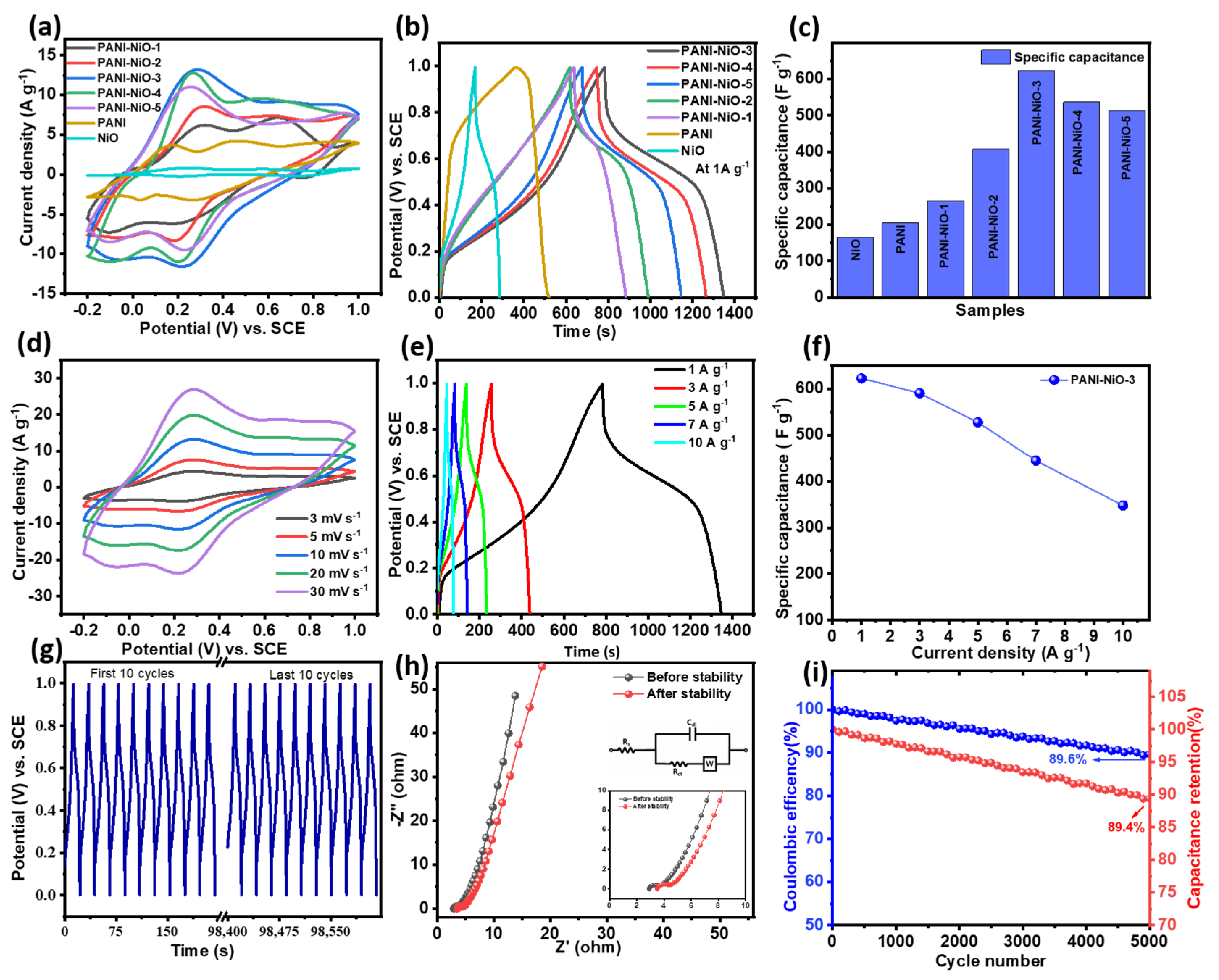
3.2. Energy Storage Performances in the 3-Electrode System

The CV, GCD, and EIS tests were used to investigate the electrochemical behavior of the PANI-NiO-x nanocomposite in the 3-electrode system with 1 M H2SO4 aqueous solution as an electrolyte. The comparative CV of PANI, NiO, and PANI-NiO-x nanocomposites at a scan rate of 10 mV s−1 in the potential window of −0.2 to 1.0 V are shown in Figure 5a. The CV curve of NiO contains a peak at 0.25 due to the oxidation of Ni2+ to Ni3+ and a peak at 0.2 due to the reduction of Ni3+ to Ni2+. The presence of redox peaks signifies the pseudocapacitive nature of NiO, distinctly different from the electric double-layer capacitance with a rectangular CV shape. The redox behavior of NiO allows for rapid faradic charge storage. The CV of PANI shows two pairs of clear redox peaks that conform to the pseudocapacitive behavior of PANI. These redox peaks reveal the redox transition between leucoemeraldine and protonated emeraldine salt, and between emeraldine and pernigraniline. The oxidization peak at about 0.18 V is due to the transformation of leucoemeraldine to conductive emeraldine salt form. The oxidization peak at 0.42 V corresponds to the transformation of the emeraldine oxidation state to a fully oxidized pernigraniline state. The reduction peaks at 0.03 V and 0.25 V are due to the transformation of the leucoemeraldine and emeraldine base, respectively. Additionally, the CV performance of the NiO-doped PANI nanocomposites (PANI-NiO-3) at various scan rates within a potential window of −0.2 V to 1.0 V are shown in Figure 5d.
The CV curve of NiO-doped PANI with different weights of NiO exhibits a clear oxidation and reduction peak which confirms the pseudocapacitive behavior of PANI-NiO composites. The NiO doping leads to a shift in both the oxidation peaks and reduction peaks of PANI. The doping of NiO results in the shifting of PANI’s oxidation peaks to a higher potential, and its reduction peak to a lower potential. PANI-NiO-1 exhibits a higher redox current than PANI. The redox peaks are shifted to 0.21 V and 0.69 V, corresponding to anodic sweep, and at 0.19 V and −0.1 V, corresponding to cathodic sweep for PANI-NiO-5, and it exhibits a higher redox current than PANI. The increase in the concentration of doped NiO from 0.1 gm to 0.5 gm on PANI leads to a further shift in the oxidation peaks to a lower potential, and in the reduction peak to a higher potential. This is the synergetic effect of the combined contributions from both NiO and PANI. From the CV curves, it is noted that the increase in area under the curve with an increase in the concentration of NiO reaches the maximum for PANI-NiO-3, and with further increases in NiO concentrations beyond PANI-NiO-3, the area has significantly reduced. Among the composites, PANI-NiO-3 has a larger voltammetry output current which is responsible for higher specific capacitance (Csp).
The GCD is the most widely used method to evaluate the electrochemical capacitance of materials under controlled current conditions. In this method, a constant current is applied to the working electrode and the resulting potential is measured against a reference electrode as a function of time. The GCD curves for different composite materials at a current density of 1 A g−1 are shown in Figure 5b. Thus, the calculated Csp of the composite samples according to the charge–discharge curves are shown in Table 1 and are also presented in Figure 5c in the form of a bar diagram.
The PANI-NiO-x nanocomposites exhibited higher specific capacitance than PANI and NiO. The NiO material played a major role in providing high specific capacitance due to the fast-redox reactions. At the same time, the PANI material, covering the surface of NiO material, acted in a supporting role by optimizing pore structures and boosting mass transfer processes, which helped the redox reactions of NiO to proceed quickly and completely. Furthermore, the PANI material could shape the surface of the NiO electrode and elaborately introduce porous structures over it [39]. In other words, the PANI material might not store charges on its own but it did improve the capability of the NiO material. Each component synergistically serves a specific purpose. Due to these synergistic effects, this composite can offer many more advantages than one pure electrode material [40]. The study reveals that as the amount of NiO is increased from 0.1 gm to 0.3 gm in PANI, the specific capacitance starts to decrease. As shown in Figure 5e, the specific capacitance for sample PANI-NiO-3 was found to be a maximum of 623 F g−1 at 1 A g−1 due to the synergistic effect of PANI and NiO. Similarly, the sample PANI-NiO-3 has a specific capacitance of 591, 528, 445, and 348 F g−1 at current densities of 3, 5, 7, and 10 A g−1, respectively (as presented in Figure 5f). The PANI-NiO-3 sample has a rate capability of 55.9% capacitance retention, even when the current density was increased ten-fold. The observed charge–discharge curve of NiO does not show straight lines, indicating faradic capacitance based on redox reaction. The sudden drop in voltage that was observed during discharge could be explained by an ohmic loss due to internal resistance (IR), also known as the ESR of the electrode. The ESR of NiO is high, due to which deviation in linearity is low, and as a result, it has low specific capacitance. Its specific capacitance is found to be 165 F g−1 at a current density of 1 A g−1. A charge–discharge experiment at 20 A g−1 was also used to investigate the cycle life of PANI-NiO-3 nanocomposite electrode materials. The first and last 10 GCD curves during the 5000-cycles stability test are presented in Figure 5g. Even after 5000 cycles, the material retains 89.4% capacitance and 89.6% coulombic efficiency of its initial value, demonstrating that it has a remarkable life cycle with significant coulombic efficiency, as shown in Figure 5i.
The EIS analytical technique was used to further elaborate the electrochemical properties of PANI-NiO-3 nanocomposite electrode materials, displayed in Figure 5h. A nearly vertical line is observed, indicating the electrode material’s pseudo-capacitive behavior and the diffusion behavior of the electrolyte. Furthermore, at high frequencies, the nanocomposite electrode materials have an almost semi-circle appearance (as shown in the inset figure in Figure 5h), illustrating the lower-charge transfer resistance (Rct). The charge transfer resistance (Rct) and inherent resistance (Rs) of the PANI-NiO-3 before the stability test were found to be 0.34 and 2.73 Ω, respectively. The charge transfer resistance (Rct) and solution resistance (Rs) of composite materials PANI-NiO-3 after the stability test were found to be 0.81 and 3.46 Ω, respectively. The small changes in the resistance values of electrode materials after a cyclic stability test (5000 cycles) demonstrate the remarkable efficiency of the as-prepared electrode materials with high stability. The observed electrochemical behavior of as-prepared electrode material inspires the practical application of supercapacitors for energy storage applications.

4. Conclusions

PANI-NiO nanocomposites were successfully synthesized by in-situ aqueous oxidative polymerization of aniline in the presence of the different amounts of NiO using ammonium persulphate as an oxidant in the H2SO4 solution. NiO nanoparticles are incorporated in porous PANI nanostructures for the preparation of homogenous nanocomposites of PANI-NiO-x. The PANI-NiO-x exhibited improved electrochemical performance, such as high specific capacitance (623 F g−1 at 1 A g−1) and long-term cycle stability with an excellent rate capability. This study demonstrated that PANI-NiO-3s can be promising electrode materials for supercapacitors application. This finding could also pave the way for the development of low-energy, low-cost PANI-NiO-3 nanocomposite-electrode material preparation techniques.

Supplementary Materials

The following supporting information can be downloaded at: https://www.mdpi.com/article/10.3390/inorganics10060086/s1, Figure S1. (a) Fe-SEM image of PANI-NiO-1, (b) EDX analysis of PANI-NiO-1, (c) Fe-SEM image of PANI-NiO-2, (d) EDX analysis of PANI-NiO-2, (e) Fe-SEM image of PANI-NiO-4, (f) EDX analysis of PANI-NiO-4, (g) Fe-SEM image of PANI-NiO-5, (h) EDX analysis of PANI-NiO-5; Figure S2. (a) XRD pattern of PANI, NiO, PANI-NiO-5, PANI-NiO-4, PANI-NiO-2 and PANI-NiO-1, and (b) FTIR spectra of PANI-NiO-1, PANI-NiO-2, PANI-NiO-4, and PANI-NiO-5 composites; Figure S3. (a) FTIR spectra of PANI, and (b) FTIR spectra of NiO nanoparticles; Figure S4. UV-visible spectra of (a) NiO, (b) PANI, (c) PANI-NiO-1, (d) PANI-NiO-2, (e) PANI-NiO-3, (f) PANI-NiO-4, (g) PANI-NiO-5 and corresponding Tauc plot.

Author Contributions

Conceptualization, K.C. and A.P.Y.; Data curation, V.S., M.D., S.N., J.K. and A.P.Y.; Formal analysis, K.P.G., D.A., I.B., V.S., M.D., S.N., J.K., K.C. and A.P.Y.; Funding acquisition, A.P.Y.; Investigation, K.P.G., I.B., K.C. and A.P.Y.; Project administration, A.P.Y.; Resources, A.P.Y.; Supervision, K.C. and A.P.Y.; Validation, K.C. and A.P.Y.; Visualization, K.P.G., D.A. and A.P.Y.; Writing—original draft, K.P.G. and D.A.; Writing—review and editing, K.P.G., K.C. and A.P.Y. All authors have read and agreed to the published version of the manuscript.

Funding

This research was funded by the Faculty Research Grant 2072/074 provided by University Grants Commission, Sanothimi, Nepal.

Institutional Review Board Statement

Not applicable.

Informed Consent Statement

Not applicable.

Data Availability Statement

Not applicable.

Acknowledgments

We would like to thank the Nepal Academy of Science and Technology (NAST), Kathmandu, Nepal for the XRD characterization and the Institute of Metal Research, Shenyang, China for SEM and EDX.

Conflicts of Interest

The authors declare no conflict of interest.

References

  1. Meng, Q.; Cai, K.; Chen, Y.; Chen, L. Research progress on conducting polymer based supercapacitor electrode materials. Nano Energy 2017, 36, 268–285. [Google Scholar] [CrossRef]
  2. Cherusseri, J.; Choudhary, N.; Sambath Kumar, K.; Jung, Y.; Thomas, J. Recent trends in transition metal dichalcogenide based supercapacitor electrodes. Nanoscale Horiz. 2019, 4, 840–858. [Google Scholar] [CrossRef]
  3. Chhetri, K.; Subedi, S.; Muthurasu, A.; Ko, T.H.; Dahal, B.; Kim, H.Y. A review on nanofiber reinforced aerogels for energy storage and conversion applications. J. Energy Storage 2022, 46, 103927. [Google Scholar] [CrossRef]
  4. Sharma, K.; Arora, A.; Tripathi, S.K. Review of supercapacitors: Materials and devices. J. Energy Storage 2019, 21, 801–825. [Google Scholar] [CrossRef]
  5. Gholivand, M.B.; Heydari, H.; Abdolmaleki, A.; Hosseini, H. Nanostructured CuO/PANI composite as supercapacitor electrode material. Mater. Sci. Semicond. Process. 2015, 30, 157–161. [Google Scholar] [CrossRef]
  6. Chatterjee, D.P.; Nandi, A.K. A review on the recent advances in hybrid supercapacitors. J. Mater. Chem. A 2021, 9, 15880–15918. [Google Scholar] [CrossRef]
  7. Bhattarai, R.M.; Chhetri, K.; Natarajan, S.; Saud, S.; Kim, S.J.; Mok, Y.S. Activated carbon derived from cherry flower biowaste with a self-doped heteroatom and large specific surface area for supercapacitor and sodium-ion battery applications. Chemosphere 2022, 303, 135290. [Google Scholar] [CrossRef]
  8. Aziz, S.B.; Brza, M.A.; Mishra, K.; Hamsan, M.H.; Karim, W.O.; Abdullah, R.M.; Kadir, M.F.Z.; Abdulwahid, R.T. Fabrication of high performance energy storage EDLC device from proton conducting methylcellulose: Dextran polymer blend electrolytes. J. Mater. Res. Technol. 2020, 9, 1137–1150. [Google Scholar] [CrossRef]
  9. Wang, Y.; Song, Y.; Xia, Y. Electrochemical capacitors: Mechanism, materials, systems, characterization and applications. Chem. Soc. Rev. 2016, 45, 5925–5950. [Google Scholar] [CrossRef]
  10. Kim, T.; Subedi, S.; Dahal, B.; Chhetri, K.; Mukhiya, T.; Muthurasu, A.; Gautam, J.; Lohani, P.C.; Acharya, D.; Pathak, I.; et al. Homogeneous Elongation of N-Doped CNTs over Nano-Fibrillated Hollow-Carbon-Nanofiber: Mass and Charge Balance in Asymmetric Supercapacitors Is no Longer Problematic. Adv. Sci. 2022, 2200650. [Google Scholar] [CrossRef]
  11. Zhang, L.; Hu, X.; Wang, Z.; Sun, F.; Dorrell, D.G. A review of supercapacitor modeling, estimation, and applications: A control/management perspective. Renew. Sustain. Energy Rev. 2018, 81, 1868–1878. [Google Scholar] [CrossRef]
  12. Wang, G.; Zhang, L.; Zhang, J. A review of electrode materials for electrochemical supercapacitors. Chem. Soc. Rev. 2012, 41, 797–828. [Google Scholar] [CrossRef] [PubMed] [Green Version]
  13. Rehman, J.; Eid, K.; Ali, R.; Fan, X.; Murtaza, G.; Faizan, M.; Laref, A.; Zheng, W.; Varma, R.S. Engineering of Transition Metal Sulfide Nanostructures as Efficient Electrodes for High-Performance Supercapacitors. ACS Appl. Energy Mater. 2022. [Google Scholar] [CrossRef]
  14. Chhetri, K.; Dahal, B.; Tiwari, A.P.; Mukhiya, T.; Muthurasu, A.; Ojha, G.P.; Lee, M.; Kim, T.; Chae, S.-H.; Kim, H.Y. Controlled Selenium Infiltration of Cobalt Phosphide Nanostructure Arrays from a Two-Dimensional Cobalt Metal–Organic Framework: A Self-Supported Electrode for Flexible Quasi-Solid-State Asymmetric Supercapacitors. ACS Appl. Energy Mater. 2021, 4, 404–415. [Google Scholar] [CrossRef]
  15. Shen, L.; Yu, L.; Wu, H.B.; Yu, X.-Y.; Zhang, X.; Lou, X.W. Formation of nickel cobalt sulfide ball-in-ball hollow spheres with enhanced electrochemical pseudocapacitive properties. Nat. Commun. 2015, 6, 6694. [Google Scholar] [CrossRef] [PubMed]
  16. Bhojane, P. Recent advances and fundamentals of Pseudocapacitors: Materials, mechanism, and its understanding. J. Energy Storage 2022, 45, 103654. [Google Scholar] [CrossRef]
  17. Bhattarai, R.M.; Chhetri, K.; Saud, S.; Teke, S.; Kim, S.J.; Mok, Y.S. Eco-Friendly Synthesis of Cobalt Molybdenum Hydroxide 3d Nanostructures on Carbon Fabric Coupled with Cherry Flower Waste-Derived Activated Carbon for Quasi-Solid-State Flexible Asymmetric Supercapacitors. ACS Appl. Nano Mater. 2022, 5, 160–175. [Google Scholar] [CrossRef]
  18. Tiwari, A.P.; Chhetri, K.; Kim, H.; Ji, S.; Chae, S.-H.; Kim, T.; Kim, H.Y. Self-assembled polypyrrole hierarchical porous networks as the cathode and porous three dimensional carbonaceous networks as the anode materials for asymmetric supercapacitor. J. Energy Storage 2021, 33, 102080. [Google Scholar] [CrossRef]
  19. Zhang, Y.; Li, L.; Su, H.; Huang, W.; Dong, X. Binary metal oxide: Advanced energy storage materials in supercapacitors. J. Mater. Chem. A 2015, 3, 43–59. [Google Scholar] [CrossRef]
  20. Sun, J.; Guo, L.; Sun, X.; Zhang, J.; Hou, L.; Li, L.; Yang, S.; Yuan, C. One-Dimensional Nanostructured Pseudocapacitive Materials: Design, Synthesis and Applications in Supercapacitors. Batter. Supercaps 2019, 2, 820–841. [Google Scholar] [CrossRef]
  21. Salunkhe, R.R.; Hsu, S.-H.; Wu, K.C.W.; Yamauchi, Y. Large-Scale Synthesis of Reduced Graphene Oxides with Uniformly Coated Polyaniline for Supercapacitor Applications. ChemSusChem 2014, 7, 1551–1556. [Google Scholar] [CrossRef] [PubMed]
  22. Ryu, K.S.; Kim, K.M.; Park, N.-G.; Park, Y.J.; Chang, S.H. Symmetric redox supercapacitor with conducting polyaniline electrodes. J. Power Sources 2002, 103, 305–309. [Google Scholar] [CrossRef]
  23. Jeyaranjan, A.; Sakthivel, T.S.; Neal, C.J.; Seal, S. Scalable ternary hierarchical microspheres composed of PANI/ rGO/CeO2 for high performance supercapacitor applications. Carbon 2019, 151, 192–202. [Google Scholar] [CrossRef]
  24. Ghosh, D.; Giri, S.; Mandal, A.; Das, C.K. Supercapacitor based on H+ and Ni2+ co-doped polyaniline–MWCNTs nanocomposite: Synthesis and electrochemical characterization. RSC Adv. 2013, 3, 11676–11685. [Google Scholar] [CrossRef]
  25. Chhetri, K.; Yadav, A.P. Electrochemical Behavior of Polyaniline (Pani) Doped with Different Nitrate Salts. J. Univ. Grant Commision 2018, 7, 14–24. [Google Scholar]
  26. Sumboja, A.; Wang, X.; Yan, J.; Lee, P.S. Nanoarchitectured current collector for high rate capability of polyaniline based supercapacitor electrode. Electrochim. Acta 2012, 65, 190–195. [Google Scholar] [CrossRef]
  27. Agudosi, E.S.; Abdullah, E.C.; Numan, A.; Mubarak, N.M.; Aid, S.R.; Benages-Vilau, R.; Gómez-Romero, P.; Khalid, M.; Omar, N. Fabrication of 3D binder-free graphene NiO electrode for highly stable supercapattery. Sci. Rep. 2020, 10, 11214. [Google Scholar] [CrossRef]
  28. Chapagain, A.; Acharya, D.; Das, A.K.; Chhetri, K.; Oli, H.B.; Yadav, A.P. Alkaloid of Rhynchostylis retusa as Green Inhibitor for Mild Steel Corrosion in 1 M H2SO4 Solution. Electrochem 2022, 3, 211–224. [Google Scholar] [CrossRef]
  29. El-Kemary, M.; Nagy, N.; El-Mehasseb, I. Nickel oxide nanoparticles: Synthesis and spectral studies of interactions with glucose. Mater. Sci. Semicond. Process. 2013, 16, 1747–1752. [Google Scholar] [CrossRef]
  30. Du, Y.; Wang, W.; Li, X.; Zhao, J.; Ma, J.; Liu, Y.; Lu, G. Preparation of NiO nanoparticles in microemulsion and its gas sensing performance. Mater. Lett. 2012, 68, 168–170. [Google Scholar] [CrossRef]
  31. Alagiri, M.; Ponnusamy, S.; Muthamizhchelvan, C. Synthesis and characterization of NiO nanoparticles by sol–gel method. J. Mater. Sci. Mater. Electron. 2012, 23, 728–732. [Google Scholar] [CrossRef]
  32. Xu, J.; Wang, M.; Liu, Y.; Li, J.; Cui, H. One-pot solvothermal synthesis of size-controlled NiO nanoparticles. Adv. Powder Technol. 2019, 30, 861–868. [Google Scholar] [CrossRef]
  33. Bahari Molla Mahaleh, Y.; Sadrnezhaad, S.K.; Hosseini, D. NiO Nanoparticles Synthesis by Chemical Precipitation and Effect of Applied Surfactant on Distribution of Particle Size. J. Nanomater. 2008, 2008, 470595. [Google Scholar] [CrossRef] [Green Version]
  34. Al-Sehemi, A.G.; Al-Shihri, A.S.; Kalam, A.; Du, G.; Ahmad, T. Microwave synthesis, optical properties and surface area studies of NiO nanoparticles. J. Mol. Struct. 2014, 1058, 56–61. [Google Scholar] [CrossRef]
  35. Mohseni Meybodi, S.; Hosseini, S.A.; Rezaee, M.; Sadrnezhaad, S.K.; Mohammadyani, D. Synthesis of wide band gap nanocrystalline NiO powder via a sonochemical method. Ultrason. Sonochem. 2012, 19, 841–845. [Google Scholar] [CrossRef]
  36. Qi, Y.; Zhang, J.; Qiu, S.; Sun, L.; Xu, F.; Zhu, M.; Ouyang, L.; Sun, D. Thermal stability, decomposition and glass transition behavior of PANI/NiO composites. J. Therm. Anal. Calorim. 2009, 98, 533. [Google Scholar] [CrossRef]
  37. Shambharkar, B.H.; Umare, S.S. Synthesis and characterization of polyaniline/NiO nanocomposite. J. Appl. Polym. Sci. 2011, 122, 1905–1912. [Google Scholar] [CrossRef]
  38. Wu, X.; Wang, Q.; Zhang, W.; Wang, Y.; Chen, W. Nano nickel oxide coated graphene/polyaniline composite film with high electrochemical performance for flexible supercapacitor. Electrochim. Acta 2016, 211, 1066–1075. [Google Scholar] [CrossRef]
  39. Singu, B.S.; Palaniappan, S.; Yoon, K.R. Polyaniline–nickel oxide nanocomposites for supercapacitor. J. Appl. Electrochem. 2016, 46, 1039–1047. [Google Scholar] [CrossRef]
  40. Chhetri, K.; Dahal, B.; Mukhiya, T.; Tiwari, A.P.; Muthurasu, A.; Kim, T.; Kim, H.; Kim, H.Y. Integrated hybrid of graphitic carbon-encapsulated CuxO on multilayered mesoporous carbon from copper MOFs and polyaniline for asymmetric supercapacitor and oxygen reduction reactions. Carbon 2021, 179, 89–99. [Google Scholar] [CrossRef]
  41. Chhetri, K.; Tiwari, A.P.; Dahal, B.; Ojha, G.P.; Mukhiya, T.; Lee, M.; Kim, T.; Chae, S.-H.; Muthurasu, A.; Kim, H.Y. A ZIF-8-derived nanoporous carbon nanocomposite wrapped with Co3O4-polyaniline as an efficient electrode material for an asymmetric supercapacitor. J. Electroanal. Chem. 2020, 856, 113670. [Google Scholar] [CrossRef]
  42. Bian, C.; Yu, A.; Wu, H. Fibriform polyaniline/nano-TiO2 composite as an electrode material for aqueous redox supercapacitors. Electrochem. Commun. 2009, 11, 266–269. [Google Scholar] [CrossRef]
  43. Chelliah, M.; Rayappan, J.B.B.; Krishnan, U.M. Synthesis and characterization of cerium oxide nanoparticles by hydroxide mediated approach. J. Appl. Sci. 2012, 12, 1734–1737. [Google Scholar] [CrossRef] [Green Version]
  44. Bhattarai, R.M.; Moopri Singer Pandiyarajan, S.; Saud, S.; Kim, S.J.; Mok, Y.S. Synergistic effects of nanocarbon spheres sheathed on a binderless CoMoO4 electrode for high-performance asymmetric supercapacitor. Dalton Trans. 2020, 49, 14506–14519. [Google Scholar] [CrossRef] [PubMed]
  45. Pilban Jahromi, S.; Pandikumar, A.; Goh, B.T.; Lim, Y.S.; Basirun, W.J.; Lim, H.N.; Huang, N.M. Influence of particle size on performance of a nickel oxide nanoparticle-based supercapacitor. RSC Adv. 2015, 5, 14010–14019. [Google Scholar] [CrossRef]
  46. Bhattarai, S.; Devkota, N.B.; Neupane, S.; Gupta, D.K.; Yadav, A.P. Synthesis and Characterization of Acid Doped Polyaniline for Super Capacitor Application. J. Nepal Chem. Soc. 2017, 37, 49–54. [Google Scholar] [CrossRef]
  47. Pandey, S.; Neupane, S.; Gupta, D.K.; Das, A.K.; Karki, N.; Singh, S.; Yadav, R.J.; Yadav, A.P. Ce-Doped PANI/Fe3O4 Nanocomposites: Electrode Materials for Supercapattery. Front. Chem. Eng. 2021, 3, 650301. [Google Scholar] [CrossRef]
  48. Chakrabarty, S.; Chatterjee, K. Synthesis and characterization of nano-dimensional nickelous oxide (NiO) semiconductor. J. Phys. Sci. 2009, 13, 245–250. [Google Scholar]
  49. Atta, A.; Abdelhamied, M.M.; Essam, D.; Shaban, M.; Alshammari, A.H.; Rabia, M. Structural and physical properties of polyaniline/silver oxide/silver nanocomposite electrode for supercapacitor applications. Int. J. Energy Res. 2022, 46, 6702–6710. [Google Scholar] [CrossRef]
  50. Makuła, P.; Pacia, M.; Macyk, W. How To Correctly Determine the Band Gap Energy of Modified Semiconductor Photocatalysts Based on UV–Vis Spectra. J. Phys. Chem. Lett. 2018, 9, 6814–6817. [Google Scholar] [CrossRef] [Green Version]
  51. Raghu, M.S.; Kumar, K.Y.; Rao, S.; Aravinda, T.; Prasanna, B.P.; Prashanth, M.K. Fabrication of polyaniline–few-layer MoS2 nanocomposite for high energy density supercapacitors. Polym. Bull. 2018, 75, 4359–4375. [Google Scholar] [CrossRef]
Figure 1. Schematic representation of the preparation of the PANI-NiO-x nanocomposites.
Inorganics 10 00086 g001
Figure 2. (a) SEM image of PANI, (b) EDX analysis of PANI, (c) SEM image of NiO, (d) EDX analysis of NiO, (e) SEM image of PANI-NiO-3, and (f) EDX analysis of PANI-NiO-3.
Inorganics 10 00086 g002
Figure 3. (a) XRD pattern of PANI, NiO, and PANI-NiO-3, and (b) FTIR spectra of PANI, NiO and PANI-NiO-3.
Inorganics 10 00086 g003
Figure 4. (a) UV-visible spectra, and (b) corresponding Tauc-plot of PANI-NiO-3.
Inorganics 10 00086 g004
Figure 5. (a) CV curves of PANI, NiO, PANI-NiO-1, PANI-NiO-2, PANI-NiO-3, PANI-NiO-4, and PANI-NiO-5 at a scan rate of 5 mV s−1; (b) GCD curves of PANI, NiO, PANI-NiO-1, PANI-NiO-2, PANI-NiO-3, PANI-NiO-4, and PANI-NiO-5 at 1 A g−1; (c) comparative study of specific capacitance of PANI, NiO, PANI-NiO-1, PANI-NiO-2, PANI-NiO-3, PANI-NiO-4, and PANI-NiO-5 at 1 A g−1; (d) C V curves of PANI-NiO-3 at various scan rates; (e) GCD curves of PANI-NiO-3 at various current densities; (f) plot of specific capacitance vs. current densities of PANI-NiO-3; (g) stability test of PANI-NiO-3 at a current density of 20 A g−1; (h) EIS plot of PANI-NiO-3 before and after stability test; (i) charge/discharging cycle number changes specific capacitance and Coulombic efficiency of PANI-NiO-3 at 20 A g−1 current densities.
Inorganics 10 00086 g005
Table 1. Specific capacitance (Cs) of different nano and composite materials at a current density of 1 A g−1.
Electrode MaterialsPANINiOPANI-NiO-1PANI-NiO-2PANI-NiO-3PANI-NiO-4PANI-NiO-5
Specific capacitance (F g−1)205165265407623537514
Publisher’s Note: MDPI stays neutral with regard to jurisdictional claims in published maps and institutional affiliations.

