
Nanostructured Iridium Oxide: State of the Art


Abstract
:1. Introduction

| Application | Main Features | Refs. | Current Challenge |
|---|---|---|---|
| Electrochromic devices | Fast colour change | [40,42,70] | Application in flexible devices (IrO2 is a rigid material) |
| OER | High catalytic activity High stability in acidic media | [71,72,73,74,75] | Deep understanding of the OER mechanism over IrO2 |
| Sensing | Stability repeatability | [46,47,55] [76,77] | Standardization of electrode preparation methods (dependence of pH response of IrO2) Improvement of stability over the pH range of 12–14 Improve sensing sensitivity Lowering the working temperature in gas sensing |
| Supercapacitor | High conductivity | [68,78] | Increase of the durability of the electrode (slight worsening of performance after 2000 charge/discharge cycles at 0.5 mA) |
| Field Emission Cathode | Low chemical reactivity Thermal stability Low work function | [65,79,80] | Achieve high aspect structures to enable operation at low applied fields Insure long-term device operation under adverse vacuum conditions |
2. IrO2 Spherical Nanoparticles and Nanopowder
3. IrO2 1D-Nanostructures
3.1. IrO2 Nanotubes
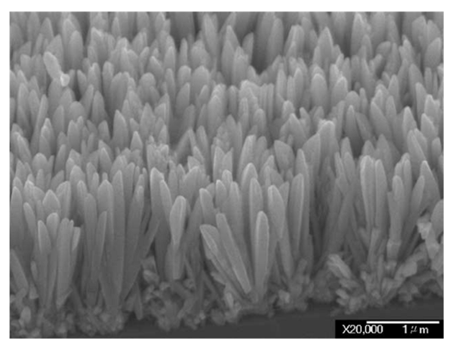
3.2. IrO2 Nanorods
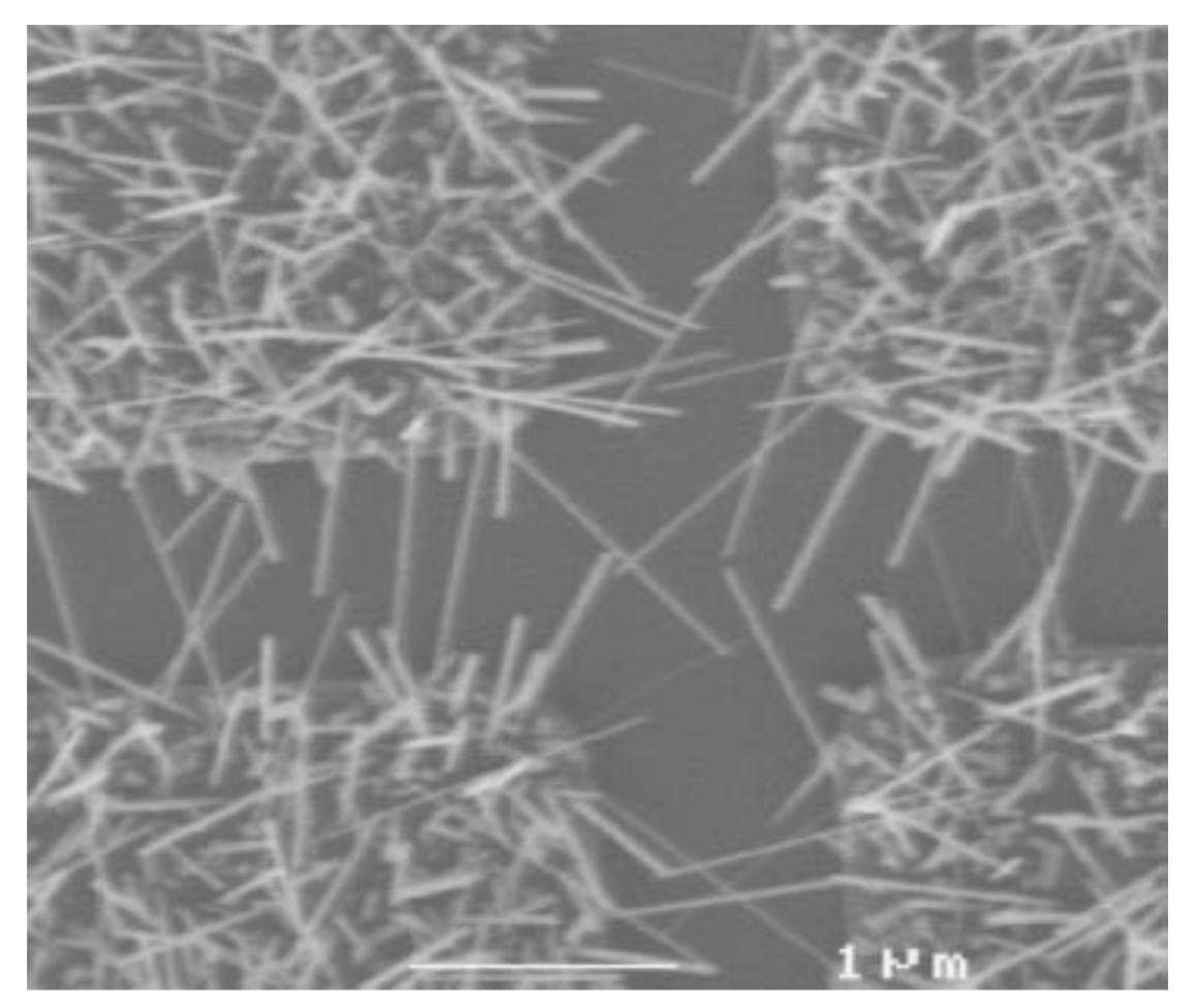
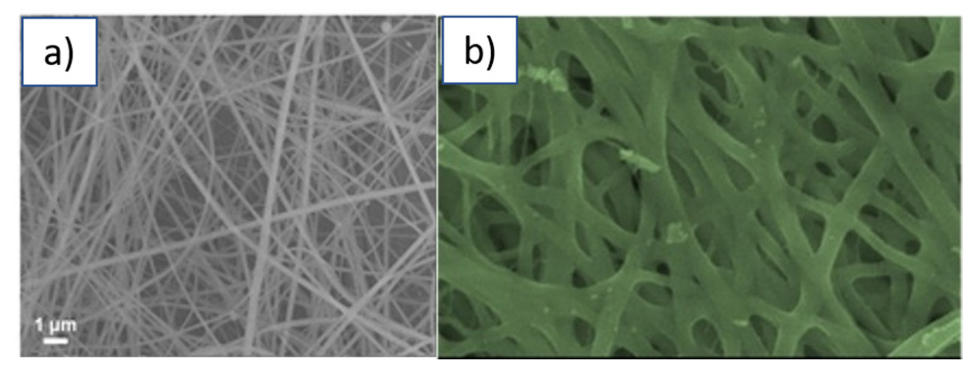
3.3. IrO2 Nanowires/Nanofibres
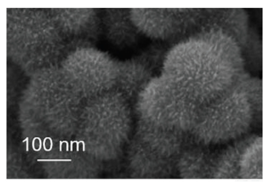
4. IrO2 Nanostructures with Unusual Shapes
5. IrO2 Nanostructured Films
6. Conclusions
Author Contributions
Funding
Conflicts of Interest
References
- Rogers, D.B.; Shannon, R.D.; Sleight, A.W.; Gillson, J.L. Crystal Chemistry of Metal Dioxides with Rutile-Related Structures. Inorg. Chem. 1969, 8, 841–849. [Google Scholar] [CrossRef]
- Cambridge Crystallographic Data Centre (CCDC), ICSD 640885, deposition number: 1759474. Available online: https://www.ccdc.cam.ac.uk/ (accessed on 2 July 2022).
- Schultze, J.W.; Trasatti, S. (Eds.) Electrodes of Conductive Metallic Oxides, Part B. Elsevier Scientific Publishing Company, Amsterdam/New York 1981. 702 Seiten, Preis: US $ 83.00/Dfl 170.00. In Berichte der Bunsengesellschaft für Physikalische Chemie; John and Wiley and Sons: Hoboken, NJ, USA, 1981; Volume 85, p. 1085. [Google Scholar] [CrossRef]
- Riga, J.; Tenret-Noël, C.; Pireaux, J.J.; Caudano, R.; Verbist, J.J.; Gobillon, Y. Electronic Structure of Rutile Oxides TiO2, RuO2 and IrO2 Studied by X-ray Photoelectron Spectroscopy. Phys. Scr. 1977, 16, 351–354. [Google Scholar] [CrossRef]
- Chen, R.S.; Huang, Y.S.; Liang, Y.M.; Tsai, D.S.; Tiong, K.K. Growth and Characterization of Iridium Dioxide Nanorods. J. Alloys Compd. 2004, 383, 273–276. [Google Scholar] [CrossRef]
- Sheng, X.; Li, Z.; Cheng, Y. Electronic and Thermoelectric Properties of V2O5, MgV2O5, and CaV2O5. Coatings 2020, 10, 453. [Google Scholar] [CrossRef]
- Liu, Y.; Masumoto, H.; Goto, T. Preparation of IrO2 Thin Films by Oxydating Laser-ablated Ir. Mater. Trans. 2004, 45, 900. [Google Scholar] [CrossRef] [Green Version]
- Greiner, M.T.; Lu, Z.-H. Thin-Film Metal Oxides in Organic Semiconductor Devices: Their Electronic Structures, Work Functions and Interfaces. NPG Asia Mater. 2013, 5, e55. [Google Scholar] [CrossRef]
- Xu, B.; Sohn, H.Y.; Mohassab, Y.; Lan, Y. Structures, Preparation and Applications of Titanium Suboxides. RSC Adv. 2016, 6, 79706–79722. [Google Scholar] [CrossRef]
- Yoo, S.-J.; Chang, J.-H.; Lee, J.-H.; Moon, C.-K.; Wu, C.-I.; Kim, J.-J. Formation of Perfect Ohmic Contact at Indium Tin Oxide/N,N′-Di(Naphthalene-1-Yl)-N,N′-Diphenyl-Benzidine Interface Using ReO3. Sci. Rep. 2015, 4, 3902. [Google Scholar] [CrossRef] [Green Version]
- Pearsall, T.P.; Lee, C.A. Electronic Transport in ReO3: Dc Conductivity and Hall Effect. Phys. Rev. B 1974, 10, 2190–2194. [Google Scholar] [CrossRef]
- Ben-Dor, L.; Shimony, Y. Crystal Structure, Magnetic Susceptibility and Electrical Conductivity of Pure and NiO-Doped MoO2 and WO2. Mater. Res. Bull. 1974, 9, 837–844. [Google Scholar] [CrossRef]
- Lakshminarayana, G.; Kityk, I.V.; Nagao, T. Synthesis, Structural, and Electrical Characterization of RuO2 Sol–Gel Spin-Coating Nano-Films. J. Mater. Sci. Mater. Electron. 2016, 27, 10791–10797. [Google Scholar] [CrossRef] [Green Version]
- Murakami, Y.; Li, J.; Shimoda, T. Highly Conductive Ruthenium Oxide Thin Films by a Low-Temperature Solution Process and Green Laser Annealing. Mater. Lett. 2015, 152, 121–124. [Google Scholar] [CrossRef] [Green Version]
- Wang, G.; Zheng, J.; Xu, B.; Zhang, C.; Zhu, Y.; Fang, Z.; Yang, Z.; Shang, M.-H.; Yang, W. Tailored Electronic Band Gap and Valance Band Edge of Nickel Oxide via P-Type Incorporation. J. Phys. Chem. C 2021, 125, 7495–7501. [Google Scholar] [CrossRef]
- Jundale, D.M.; Joshi, P.B.; Sen, S.; Patil, V.B. Nanocrystalline CuO Thin Films: Synthesis, Microstructural and Optoelectronic Properties. J. Mater. Sci. Mater. Electron. 2012, 23, 1492–1499. [Google Scholar] [CrossRef]
- Johan, M.R.; Suan, M.S.M.; Hawari, N.L.; Ching, H.A. Annealing Effects on the Properties of Copper Oxide Thin Films Prepared by Chemical Deposition. Int. J. Electrochem. Sci. 2011, 6, 6094–6104. [Google Scholar]
- Chang, X.; Wang, T.; Zhang, P.; Zhang, J.; Li, A.; Gong, J. Enhanced Surface Reaction Kinetics and Charge Separation of p–n Heterojunction Co3O4/BiVO4 Photoanodes. J. Am. Chem. Soc. 2015, 137, 8356–8359. [Google Scholar] [CrossRef]
- Savio, A.K.P.D.; Fletcher, J.; Smith, K.; Iyer, R.; Bao, J.M.; Robles Hernández, F.C. Environmentally Effective Photocatalyst CoO–TiO2 Synthesized by Thermal Precipitation of Co in Amorphous TiO2. Appl. Catal. B Environ. 2016, 182, 449–455. [Google Scholar] [CrossRef]
- Scarpelli, F.; Mastropietro, T.F.; Poerio, T.; Godbert, N. Mesoporous TiO2 Thin Films: State of the Art. In Titanium Dioxide—Material for a Sustainable Environment; InTech: London, UK, 2018. [Google Scholar]
- Carcia, P.F.; McCarron, E.M. Synthesis and Properties of Thin Film Polymorphs of Molybdenum Trioxide. Thin Solid Films 1987, 155, 53–63. [Google Scholar] [CrossRef]
- González-Borrero, P.P.; Sato, F.; Medina, A.N.; Baesso, M.L.; Bento, A.C.; Baldissera, G.; Persson, C.; Niklasson, G.A.; Granqvist, C.G.; Ferreira da Silva, A. Optical Band-Gap Determination of Nanostructured WO3 Film. Appl. Phys. Lett. 2010, 96, 061909. [Google Scholar] [CrossRef]
- Feucht, D.L. Heterojunctions in Photovoltaic Devices. J. Vac. Sci. Technol. 1977, 14, 57–64. [Google Scholar] [CrossRef]
- Batzill, M.; Diebold, U. The Surface and Materials Science of Tin Oxide. Prog. Surf. Sci. 2005, 79, 47–154. [Google Scholar] [CrossRef]
- Pan, C.A.; Ma, T.P. Work Function of In2O3 Film as Determined from Internal Photoemission. Appl. Phys. Lett. 1980, 37, 714–716. [Google Scholar] [CrossRef]
- Weiher, R.L.; Ley, R.P. Optical Properties of Indium Oxide. J. Appl. Phys. 1966, 37, 299–302. [Google Scholar] [CrossRef]
- Wei, M.; Li, C.-F.; Deng, X.-R.; Deng, H. Surface Work Function of Transparent Conductive ZnO Films. Energy Procedia 2012, 16, 76–80. [Google Scholar] [CrossRef] [Green Version]
- Srikant, V.; Clarke, D.R. On the Optical Band Gap of Zinc Oxide. J. Appl. Phys. 1998, 83, 5447–5451. [Google Scholar] [CrossRef]
- Sotiropoulou, D.; Ladas, S. The Growth of Ultrathin Films of Copper on Polycrystalline ZrO2. Surf. Sci. 2000, 452, 58–66. [Google Scholar] [CrossRef]
- Meyer, J.; Zilberberg, K.; Riedl, T.; Kahn, A. Electronic Structure of Vanadium Pentoxide: An Efficient Hole Injector for Organic Electronic Materials. J. Appl. Phys. 2011, 110, 033710. [Google Scholar] [CrossRef]
- Trastoy, J.; Kalcheim, Y.; del Valle, J.; Valmianski, I.; Schuller, I.K. Enhanced Metal–Insulator Transition in V2O3 by Thermal Quenching after Growth. J. Mater. Sci. 2018, 53, 9131–9137. [Google Scholar] [CrossRef]
- Li, J. Oxygen Evolution Reaction in Energy Conversion and Storage: Design Strategies under and Beyond the Energy Scaling Relationship; Springer Nature Singapore: Singapore, 2022; Volume 14, ISBN 4082002200. [Google Scholar]
- Suen, N.T.; Hung, S.F.; Quan, Q.; Zhang, N.; Xu, Y.J.; Chen, H.M. Electrocatalysis for the Oxygen Evolution Reaction: Recent Development and Future Perspectives. Chem. Soc. Rev. 2017, 46, 337–365. [Google Scholar] [CrossRef]
- Ali, I.; AlGhamdi, K.; Al-Wadaani, F.T. Advances in Iridium Nano Catalyst Preparation, Characterization and Applications. J. Mol. Liq. 2019, 280, 274–284. [Google Scholar] [CrossRef]
- Naito, T.; Shinagawa, T.; Nishimoto, T.; Takanabe, K. Recent Advances in Understanding Oxygen Evolution Reaction Mechanisms over Iridium Oxide. Inorg. Chem. Front. 2021, 8, 2900–2917. [Google Scholar] [CrossRef]
- Nabor, G.S.; Hapiot, P.; Neta, P.; Harriman, A. Changes in the Redox State of Iridium Oxide Clusters and Their Relation to Catalytic Water Oxidation. Radiolytic and Electrochemical Studies. J. Phys. Chem. 1991, 95, 616–621. [Google Scholar] [CrossRef]
- Sanchezcasalongue, H.G.; Ng, M.L.; Kaya, S.; Friebel, D.; Ogasawara, H.; Nilsson, A. InSitu Observation of Surface Species on Iridium Oxide Nanoparticles during the Oxygen Evolution Reaction. Angew. Chem.-Int. Ed. 2014, 53, 7169–7172. [Google Scholar] [CrossRef] [PubMed] [Green Version]
- Abe, Y.; Ito, S.; Kim, K.H.; Kawamura, M.; Kiba, T. Electrochromic Properties of Sputtered Iridium Oxide Thin Films with Various Film Thicknesses. J. Mater. Sci. Res. 2016, 6, 44. [Google Scholar] [CrossRef] [Green Version]
- Gottesfeld, S.; McIntyre, J.D.E. Electrochromism in Anodic Iridium Oxide Films: II. PH Effects on Corrosion Stability and the Mechanism of Coloration and Bleaching. J. Electrochem. Soc. 1979, 126, 742–750. [Google Scholar] [CrossRef]
- Gottesfeld, S.; McIntyre, J.D.E.; Beni, G.; Shay, J.L. Electrochromism in Anodic Iridium Oxide Films. Appl. Phys. Lett. 1978, 33, 208–210. [Google Scholar] [CrossRef]
- Dautremont-Smith, W.C. Transition Metal Oxide Electrochromic Materials and Displays: A Review. Part 2: Oxides with Anodic Coloration. Displays 1982, 3, 67–80. [Google Scholar] [CrossRef]
- Shay, J.L.; Beni, G.; Schiavone, L.M. Electrochromism of Anodic Iridium Oxide Films on Transparent Substrates. Appl. Phys. Lett. 1978, 33, 942–944. [Google Scholar] [CrossRef]
- Ito, S.; Abe, Y.; Kawamura, M.; Kim, K.H. Electrochromic Properties of Iridium Oxide Thin Films Prepared by Reactive Sputtering in O2 or H2O Atmosphere. J. Vac. Sci. Technol. B Nanotechnol. Microelectron. Mater. Process. Meas. Phenom. 2015, 33, 041204. [Google Scholar] [CrossRef]
- Yamanaka, K. Anodically Electrodeposited Iridium Oxide Films (AEIROF) from Alkaline Solutions for Electrochromic Display Devices. Jpn. J. Appl. Phys. 1989, 28, 632–637. [Google Scholar] [CrossRef]
- Nguyen, C.M.; Huang, W.D.; Rao, S.; Cao, H.; Tata, U.; Chiao, M.; Chiao, J.C. Sol-Gel Iridium Oxide-Based PH Sensor Array on Flexible Polyimide Substrate. IEEE Sens. J. 2013, 13, 3857–3864. [Google Scholar] [CrossRef]
- Ges, I.A.; Ivanov, B.L.; Werdich, A.A.; Baudenbacher, F.J. Differential PH Measurements of Metabolic Cellular Activity in Nl Culture Volumes Using Microfabricated Iridium Oxide Electrodes. Biosens. Bioelectron. 2007, 22, 1303–1310. [Google Scholar] [CrossRef] [PubMed]
- Kuo, L.M.; Chou, Y.C.; Chen, K.N.; Lu, C.C.; Chao, S. A Precise PH Microsensor Using RF-Sputtering IrO2 and Ta2O5 Films on Pt-Electrode. Sens. Actuators B Chem. 2014, 193, 687–691. [Google Scholar] [CrossRef]
- Lee, Y.; Kang, M.; Shim, J.H.; Lee, N.S.; Baik, J.M.; Lee, Y.; Lee, C.; Kim, M.H. Growth of Highly Single Crystalline IrO2 Nanowires and Their Electrochemical Applications. J. Phys. Chem. C 2012, 116, 18550–18556. [Google Scholar] [CrossRef]
- Hitchman, M.L.; Ramanathan, S. Thermally Grown Iridium Oxide Electrodes for PH Sensing in Aqueous Environments at 0 and 95 °C. Anal. Chim. Acta 1992, 263, 53–61. [Google Scholar] [CrossRef]
- Dobson, J.V.; Snodin, P.R.; Thirsk, H.R. EMF Measurements of Cells Employing Metal—Metal Oxide Electrodes in Aqueous Chloride and Sulphate Electrolytes at Temperatures between 25–250 °C. Electrochim. Acta 1976, 21, 527–533. [Google Scholar] [CrossRef]
- Bordi, S.; Carlá, M.; Papeschi, G.; Pinzauti, S. Iridium/Iridium Oxide Electrode for Potentiometric Determination of Proton Activity in Hydroorganic Solutions at Sub-Zero Temperatures. Anal. Chem. 1984, 56, 317–319. [Google Scholar] [CrossRef]
- O’Hare, D.; Parker, K.H.; Winlove, C.P. Metal-Metal Oxide PH Sensors for Physiological Application. Med. Eng. Phys. 2006, 28, 982–988. [Google Scholar] [CrossRef]
- Bezbaruah, A.N.; Zhang, T.C. Fabrication of Anodically Electrodeposited Iridium Oxide Film PH Microelectrodes for Microenvironmental Studies. Anal. Chem. 2002, 74, 5726–5733. [Google Scholar] [CrossRef]
- Głáb, S.; Hulanicki, A.; Edwall, G.; Folke, F.; Ingman, I.; Koch, W.F. Metal-Metal Oxide and Metal Oxide Electrodes as PH Sensors. Crit. Rev. Anal. Chem. 1989, 21, 29–47. [Google Scholar] [CrossRef]
- Dong, Q.; Sun, X.; He, S. Iridium Oxide Enabled Sensors Applications. Catalysts 2021, 11, 1164. [Google Scholar] [CrossRef]
- Zhang, F.; Ulrich, B.; Reddy, R.K.; Venkatraman, V.L.; Prasad, S.; Vu, T.Q.; Hsu, S.T. Fabrication of Submicron IrO2 Nanowire Array Biosensor Platform by Conventional Complementary Metal-Oxide-Semiconductor Process. Jpn. J. Appl. Phys. 2008, 47, 1147–1151. [Google Scholar] [CrossRef]
- Quesada-González, D.; Sena-Torralba, A.; Wicaksono, W.P.; de la Escosura-Muñiz, A.; Ivandini, T.A.; Merkoçi, A. Iridium Oxide (IV) Nanoparticle-Based Lateral Flow Immunoassay. Biosens. Bioelectron. 2019, 132, 132–135. [Google Scholar] [CrossRef] [PubMed]
- Zhang, H.; Zhang, L.X.; Zhong, H.; Niu, S.; Ding, C.; Lv, S. Iridium Oxide Nanoparticles-Based Theranostic Probe for in Vivo Tumor Imaging and Synergistic Chem/Photothermal Treatments of Cancer Cells. Chem. Eng. J. 2022, 430, 132675. [Google Scholar] [CrossRef]
- Yuan, X.; Cen, J.; Chen, X.; Jia, Z.; Zhu, X.; Huang, Y.; Yuan, G.; Liu, J. Iridium Oxide Nanoparticles Mediated Enhanced Photodynamic Therapy Combined with Photothermal Therapy in the Treatment of Breast Cancer. J. Colloid Interface Sci. 2022, 605, 851–862. [Google Scholar] [CrossRef]
- Buchanan, R.A.; Lee, I.-S.; Williams, J.M. Surface Modification of Biomaterials through Noble Metal Ion Implantation. J. Biomed. Mater. Res. 1990, 24, 309–318. [Google Scholar] [CrossRef]
- Cogan, S.F.; Ehrlich, J.; Plante, T.D.; Smirnov, A.; Shire, D.B.; Gingerich, M.; Rizzo, J.F. Sputtered Iridium Oxide Films for Neural Stimulation Electrodes. J. Biomed. Mater. Res. Part B Appl. Biomater. 2009, 89B, 353–361. [Google Scholar] [CrossRef]
- Robblee, L.S.; Mangaudis, M.J.; Lasinsky, E.D.; Kimball, A.G.; Brummer, S.B. Charge Injection Properties of Thermally-Prepared Iridium Oxide Films. MRS Proc. 1985, 55, 303. [Google Scholar] [CrossRef]
- Chalamala, B.R.; Wei, Y.; Reuss, R.H.; Aggarwal, S.; Gnade, B.E.; Ramesh, R.; Bernhard, J.M.; Sosa, E.D.; Golden, D.E. Effect of Growth Conditions on Surface Morphology and Photoelectric Work Function Characteristics of Iridium Oxide Thin Films. Appl. Phys. Lett. 1999, 74, 1394–1396. [Google Scholar] [CrossRef]
- Chalamala, B.R.; Wei, Y.; Reuss, R.H.; Aggarwal, S.; Perusse, S.R.; Gnade, B.E.; Ramesh, R. Stability and Chemical Composition of Thermally Grown Iridium-Oxide Thin Films. J. Vac. Sci. Technol. B Microelectron. Nanom. Struct. 2000, 18, 1919. [Google Scholar] [CrossRef]
- Chalamala, B.R.; Reuss, R.H.; Dean, K.A.; Sosa, E.; Golden, D.E. Field Emission Characteristics of Iridium Oxide Tips. J. Appl. Phys. 2002, 91, 6141–6146. [Google Scholar] [CrossRef]
- Kubaschewski, O.; Hopkins, B.E. Oxidation of Metals and Alloys, 2nd ed.; Butterworths: London, UK, 1962. [Google Scholar]
- Baglio, V.; Sebastián, D.; D’Urso, C.; Stassi, A.; Amin, R.S.; El-Khatib, K.M.; Aricò, A.S. Composite Anode Electrode Based on Iridium Oxide Promoter for Direct Methanol Fuel Cells. Electrochim. Acta 2014, 128, 304–310. [Google Scholar] [CrossRef]
- Chen, Y.M.; Cai, J.H.; Huang, Y.S.; Lee, K.Y.; Tsai, D.S.; Tiong, K.K. A Nanostructured Electrode of IrO x Foil on the Carbon Nanotubes for Supercapacitors. Nanotechnology 2011, 22, 355708. [Google Scholar] [CrossRef] [PubMed]
- Slavcheva, E.; Vitushinsky, R.; Mokwa, W.; Schnakenberg, U. Sputtered Iridium Oxide Films as Charge Injection Material for Functional Electrostimulation. J. Electrochem. Soc. 2004, 151, E226. [Google Scholar] [CrossRef]
- Patil, P.S.; Kawar, R.K.; Sadale, S.B. Electrochromism in Spray Deposited Iridium Oxide Thin Films. Electrochim. Acta 2005, 50, 2527–2532. [Google Scholar] [CrossRef]
- Cui, Z.; Qi, R. First-Principles Simulation of Oxygen Evolution Reaction (OER) Catalytic Performance of IrO2 Bulk-like Structures: Nanosphere, Nanowire and Nanotube. Appl. Surf. Sci. 2021, 554, 149591. [Google Scholar] [CrossRef]
- Chen, Z.; Duan, X.; Wei, W.; Wang, S.; Ni, B.J. Iridium-Based Nanomaterials for Electrochemical Water Splitting. Nano Energy 2020, 78, 105270. [Google Scholar] [CrossRef]
- González, D.; Sodupe, M.; Rodríguez-Santiago, L.; Solans-Monfort, X. Surface Morphology Controls Water Dissociation on Hydrated IrO2 nanoparticles. Nanoscale 2021, 13, 14480–14489. [Google Scholar] [CrossRef]
- Chandra, D.; Abe, N.; Takama, D.; Saito, K.; Yui, T.; Yagi, M. Open Pore Architecture of an Ordered Mesoporous IrO2 Thin Film for Highly Efficient Electrocatalytic Water Oxidation. ChemSusChem 2015, 8, 795–799. [Google Scholar] [CrossRef]
- Lim, J.; Park, D.; Jeon, S.S.; Roh, C.W.; Choi, J.; Yoon, D.; Park, M.; Jung, H.; Lee, H. Ultrathin IrO2 Nanoneedles for Electrochemical Water Oxidation. Adv. Funct. Mater. 2018, 28, 1704796. [Google Scholar] [CrossRef]
- Nguyen, C.M.; Gurung, I.; Cao, H.; Rao, S.; Chiao, J.C. Fabrication of PH-Sensing Iridium Oxide Nanotubes on Patterned Electrodes Using Anodic Aluminum Oxide Nanotemplate. Proc. IEEE Sensors 2013, 2013, 1–4. [Google Scholar] [CrossRef]
- Khalil, M.; Liu, N.; Lee, R.L. Super-Nernstian Potentiometric PH Sensor Based on the Electrodeposition of Iridium Oxide Nanoparticles. Int. J. Technol. 2018, 9, 446–454. [Google Scholar] [CrossRef] [Green Version]
- Beknalkar, S.A.; Teli, A.M.; Harale, N.S.; Patil, D.S.; Pawar, S.A.; Shin, J.C.; Patil, P.S. Fabrication of High Energy Density Supercapacitor Device Based on Hollow Iridium Oxide Nanofibers by Single Nozzle Electrospinning. Appl. Surf. Sci. 2021, 546, 149102. [Google Scholar] [CrossRef]
- Park, T.J.; Jeong, D.S.; Hwang, C.S.; Park, M.S.; Kang, N.-S. Fabrication of Ultrathin IrO2 Top Electrode for Improving Thermal Stability of Metal–Insulator–Metal Field Emission Cathodes. Thin Solid Films 2005, 471, 236–242. [Google Scholar] [CrossRef]
- Chen, R.-S.; Huang, Y.-S.; Liang, Y.-M.; Hsieh, C.-S.; Tsai, D.-S.; Tiong, K.-K. Field Emission from Vertically Aligned Conductive IrO2 Nanorods. Appl. Phys. Lett. 2004, 84, 1552–1554. [Google Scholar] [CrossRef]
- Gleiter, H. Nanostructured Materials: Basic Concepts and Microstructure. Acta Mater. 2000, 48, 1–29. [Google Scholar] [CrossRef] [Green Version]
- Argon, A.S.; Yip, S. The Strongest Size. Philos. Mag. Lett. 2006, 86, 713–720. [Google Scholar] [CrossRef]
- Huang, C.; Chen, X.; Xue, Z.; Wang, T. Effect of Structure: A New Insight into Nanoparticle Assemblies from Inanimate to Animate. Sci. Adv. 2020, 6, eaba1321. [Google Scholar] [CrossRef]
- Guo, D.; Xie, G.; Luo, J. Mechanical Properties of Nanoparticles: Basics and Applications. J. Phys. D Appl. Phys. 2014, 47, 013001. [Google Scholar] [CrossRef] [Green Version]
- Khan, I.; Saeed, K.; Khan, I. Nanoparticles: Properties, Applications and Toxicities. Arab. J. Chem. 2019, 12, 908–931. [Google Scholar] [CrossRef]
- Rafique, M.; Tahir, M.B.; Rafique, M.S.; Safdar, N.; Tahir, R. Nanostructure Materials and Their Classification by Dimensionality; Elsevier: Amsterdam, The Netherlands, 2020; ISBN 9780128211922. [Google Scholar]
- Bizzotto, F.; Quinson, J.; Schröder, J.; Zana, A.; Arenz, M. Surfactant-Free Colloidal Strategies for Highly Dispersed and Active Supported IrO2 Catalysts: Synthesis and Performance Evaluation for the Oxygen Evolution Reaction. J. Catal. 2021, 401, 54–62. [Google Scholar] [CrossRef]
- Takimoto, D.; Fukuda, K.; Miyasaka, S.; Ishida, T.; Ayato, Y.; Mochizuki, D.; Shimizu, W.; Sugimoto, W. Synthesis and Oxygen Electrocatalysis of Iridium Oxide Nanosheets. Electrocatalysis 2017, 8, 144–150. [Google Scholar] [CrossRef]
- Nguyen, C.M.; Rao, S.; Chiao, J.C.; Cao, H.; Li, A.; Peng, Y.B. Miniature Neurotransmitter Sensors Featured with Iridium Oxide Nanorods. Sensors 2014, 2014, 1869–1872. [Google Scholar] [CrossRef]
- Tao, Y.; Pan, Z.; Ruch, T.; Zhan, X.; Chen, Y.; Zhang, S.X.; Li, D. Remarkable Suppression of Lattice Thermal Conductivity by Electron-Phonon Scattering in Iridium Dioxide Nanowires. Mater. Today Phys. 2021, 21, 100517. [Google Scholar] [CrossRef]
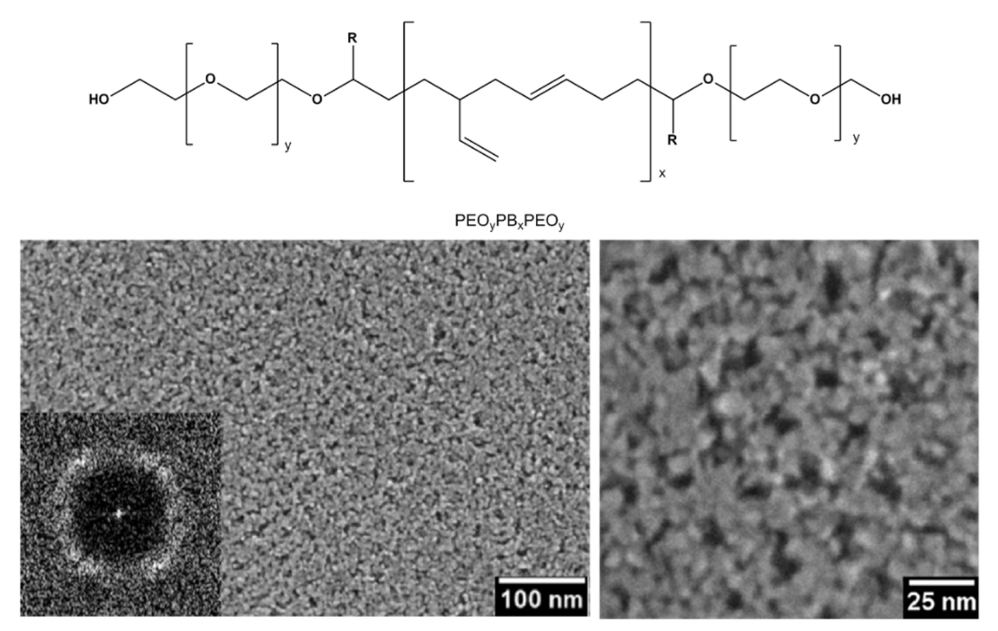
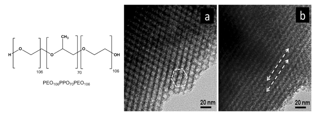
- Ortel, E.; Reier, T.; Strasser, P.; Kraehnert, R. Mesoporous IrO2 Films Templated by PEO-PB-PEO Block-Copolymers: Self-Assembly, Crystallization Behavior, and Electrocatalytic Performance. Chem. Mater. 2011, 23, 3201–3209. [Google Scholar] [CrossRef]
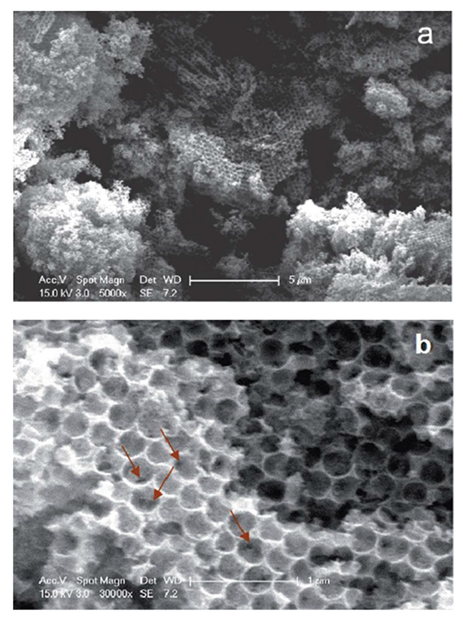
- Hu, J.; Abdelsalam, M.; Bartlett, P.; Cole, R.; Sugawara, Y.; Baumberg, J.; Mahajan, S.; Denuault, G. Electrodeposition of Highly Ordered Macroporous Iridium Oxide through Self-Assembled Colloidal Templates. J. Mater. Chem. 2009, 19, 3855–3858. [Google Scholar] [CrossRef] [Green Version]
- Quinson, J. Iridium and IrOx Nanoparticles: An Overview and Review of Syntheses and Applications. Adv. Colloid Interface Sci. 2022, 303, 102643. [Google Scholar] [CrossRef]
- Marshall, A.; Børresen, B.; Hagen, G.; Tsypkin, M.; Tunold, R. Preparation and Characterisation of Nanocrystalline IrxSn 1-XO2 Electrocatalytic Powders. Mater. Chem. Phys. 2005, 94, 226–232. [Google Scholar] [CrossRef]
- Bonet, F.; Delmas, V.; Grugeon, S.; Herrera Urbina, R.; Silvert, P.Y.; Tekaia-Elhsissen, K. Synthesis of Monodisperse Au, Pt, Pd, Ru and Ir Nanoparticles in Ethylene Glycol. Nanostructured Mater. 1999, 11, 1277–1284. [Google Scholar] [CrossRef]
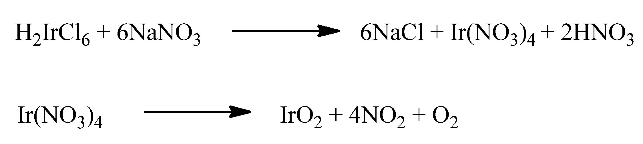
- Adams, R.; Shriner, R.L. Platinum oxide as a catalyst in the reduction of organic compounds. iii. preparation and properties of the oxide of platinum obtained by the fusion of chloroplatinic acid with sodium nitrate. J. Am. Chem. Soc. 1923, 45, 2171–2179. [Google Scholar] [CrossRef]
- Cruz, J.C.; Baglio, V.; Siracusano, S.; Ornelas, R.; Ortiz-Frade, L.; Arriaga, L.G.; Antonucci, V.; Aricò, A.S. Nanosized IrO2 Electrocatalysts for Oxygen Evolution Reaction in an SPE Electrolyzer. J. Nanoparticle Res. 2011, 13, 1639–1646. [Google Scholar] [CrossRef]
- Hu, W.; Wang, Y.; Hu, X.; Zhou, Y.; Chen, S. Three-Dimensional Ordered Macroporous IrO2 as Electrocatalyst for Oxygen Evolution Reaction in Acidic Medium. J. Mater. Chem. 2012, 22, 6010–6016. [Google Scholar] [CrossRef]
- Zhang, J.; Liu, S.; Wang, H.; Xia, Q.; Huang, X. Polypyrrole Assisted Synthesis of Nanosized Iridium Oxide for Oxygen Evolution Reaction in Acidic Medium. Int. J. Hydrog. Energy 2020, 45, 33491–33499. [Google Scholar] [CrossRef]
- Diaz, C.; Valenzuela, M.L.; Cifuentes-Vaca, O.; Segovia, M.; Laguna-Bercero, M.A. Iridium Nanostructured Metal Oxide, Its Inclusion in Silica Matrix and Their Activity toward Photodegradation of Methylene Blue. Mater. Chem. Phys. 2020, 252, 123276. [Google Scholar] [CrossRef]
- Chen, P.C.; Chen, Y.C.; Huang, C.N. Free-Standing Iridium Oxide Nanotube Array for Neural Interface Electrode Applications. Mater. Lett. 2018, 221, 293–295. [Google Scholar] [CrossRef]
- Yu, A.; Kwon, T.; Lee, C.; Lee, Y. Highly Catalytic Electrochemical Oxidation of Carbon Monoxide on Iridium Nanotubes: Amperometric Sensing of Carbon Monoxide. Nanomaterials 2020, 10, 1140. [Google Scholar] [CrossRef]
- Chen, R.S.; Huang, Y.S.; Tsai, D.S.; Chattopadhyay, S.; Wu, C.T.; Lan, Z.H.; Chen, K.H. Growth of Well Aligned IrO2 Nanotubes on LiTaO3(012) Substrate. Chem. Mater. 2004, 16, 2457–2462. [Google Scholar] [CrossRef]
- Chen, R.S.; Korotcov, A.; Huang, Y.S.; Tsai, D.S. One-Dimensional Conductive IrO2 nanocrystals. Nanotechnology 2006, 17, R67–R87. [Google Scholar] [CrossRef] [Green Version]
- Shan, C.C.; Tsai, D.S.; Huang, Y.S.; Jian, S.H.; Cheng, C.L. Pt-Ir-IrO2NT Thin-Wall Electrocatalysts Derived from IrO2 Nanotubes and Their Catalytic Activities in Methanol Oxidation. Chem. Mater. 2007, 19, 424–431. [Google Scholar] [CrossRef]
- Ahmed, J.; Mao, Y. Ultrafine Iridium Oxide Nanorods Synthesized by Molten Salt Method toward Electrocatalytic Oxygen and Hydrogen Evolution Reactions. Electrochim. Acta 2016, 212, 686–693. [Google Scholar] [CrossRef] [Green Version]
- Nguyen, C.M.; Thumthan, O.; Huang, C.; Tata, U.; Hao, Y.; Chiao, J.C. Chemical Bath Method to Grow Precipitated Nanorods of Iridium Oxide on Alumina Membranes. Micro Nano Lett. 2012, 7, 1256–1259. [Google Scholar] [CrossRef] [Green Version]
- Mohan, S.; Gupta, S.K.; Mao, Y. Morphology-Oxygen Evolution Activity Relationship of Iridium(Iv) Oxide Nanomaterials. New J. Chem. 2022, 46, 3716–3726. [Google Scholar] [CrossRef]
- Chen, R.S.; Huang, Y.S.; Liang, Y.M.; Tsai, D.S.; Chi, Y.; Kai, J.J. Growth Control and Characterization of Vertically Aligned IrO2 Nanorods. J. Mater. Chem. 2003, 13, 2525–2529. [Google Scholar] [CrossRef]
- Zhang, F.; Barrowcliff, R.; Stecker, G.; Pan, W.; Wang, D.; Hsu, S.T. Synthesis of Metallic Iridium Oxide Nanowires via Metal Organic Chemical Vapor Deposition. Jpn. J. Appl. Phys. Part 2 Lett. 2005, 44, L398–L401. [Google Scholar] [CrossRef]
- Lee, J.; Yang, H.-S.; Lee, N.-S.; Kwon, O.; Shin, H.-Y.; Yoon, S.; Baik, J.M.; Seo, Y.-S.; Kim, M.H. Hierarchically Assembled 1-Dimensional Hetero-Nanostructures: Single Crystalline RuO2 Nanowires on Electrospun IrO2 Nanofibres. CrystEngComm 2013, 15, 2367. [Google Scholar] [CrossRef] [Green Version]
- Kim, S.; Kim, Y.L.; Yu, A.; Lee, J.; Lee, S.C.; Lee, C.; Kim, M.H.; Lee, Y. Electrospun Iridium Oxide Nanofibers for Direct Selective Electrochemical Detection of Ascorbic Acid. Sens. Actuators B Chem. 2014, 196, 480–488. [Google Scholar] [CrossRef]
- Deng, Q.; Sun, Y.; Wang, J.; Chang, S.; Ji, M.; Qu, Y.; Zhang, K.; Li, B. Boosting OER Performance of IrO2 in Acid via Urchin-like Hierarchical-Structure Design. Dalt. Trans. 2021, 50, 6083–6087. [Google Scholar] [CrossRef]
- Comstock, D.J.; Christensen, S.T.; Elam, J.W.; Pellin, M.J.; Hersam, M.C. Synthesis of Nanoporous Activated Iridium Oxide Films by Anodized Aluminum Oxide Templated Atomic Layer Deposition. Electrochem. Commun. 2010, 12, 1543–1546. [Google Scholar] [CrossRef]
- Machado, A.E.H.; Borges, K.A.; Silva, T.A.; Santos, L.M.; Borges, M.F.; Machado, W.A.; Caixeta, B.P.; Oliveira, S.M.; Trovó, A.G.; Patrocínio, A.O.T. Applications of Mesoporous Ordered Semiconductor Materials—Case Study of TiO2. In Solar Radiation Applications; InTech: Rijeka, Croatia, 2015.TiO2. In Solar Radiation Applications; InTech: Rijeka, Croatia, 2015. [Google Scholar]
- Bernicke, M.; Ortel, E.; Reier, T.; Bergmann, A.; Ferreira de Araujo, J.; Strasser, P.; Kraehnert, R. Iridium Oxide Coatings with Templated Porosity as Highly Active Oxygen Evolution Catalysts: Structure-Activity Relationships. ChemSusChem 2015, 8, 1908–1915. [Google Scholar] [CrossRef]
- Chandra, D.; Sato, T.; Tanahashi, Y.; Takeuchi, R.; Yagi, M. Facile Fabrication and Nanostructure Control of Mesoporous Iridium Oxide Films for Efficient Electrocatalytic Water Oxidation. Energy 2019, 173, 278–289. [Google Scholar] [CrossRef]
- Brinker, C.J.; Lu, Y.; Sellinger, A.; Fan, H. ChemInform Abstract: Evaporation-Induced Self-Assembly: Nanostructures Made Easy. Adv. Mater. 1999, 11, 579. [Google Scholar] [CrossRef]
- Grosso, D.; Cagnol, F.; Soler-Illia, G.; Crepaldi, E.L.; Amenitsch, H.; Brunet-Bruneau, A.; Bourgeois, A.; Sanchez, C. Fundamentals of Mesostructuring through Evaporation-Induced Self-Assembly. Adv. Funct. Mater. 2004, 14, 309–322. [Google Scholar] [CrossRef]
- Scarpelli, F.; Ricciardi, L.; La Deda, M.; Brunelli, E.; Crispini, A.; Ghedini, M.; Godbert, N.; Aiello, I. A Luminescent Lyotropic Liquid-Crystalline Gel of a Water-Soluble Ir(III) Complex. J. Mol. Liq. 2021, 334, 116187. [Google Scholar] [CrossRef]
- Scarpelli, F.; Ionescu, A.; Ricciardi, L.; Plastina, P.; Aiello, I.; La Deda, M.; Crispini, A.; Ghedini, M.; Godbert, N. A Novel Route towards Water-Soluble Luminescent Iridium(III) Complexes: Via a Hydroxy-Bridged Dinuclear Precursor. Dalt. Trans. 2016, 45, 17264–17273. [Google Scholar] [CrossRef]
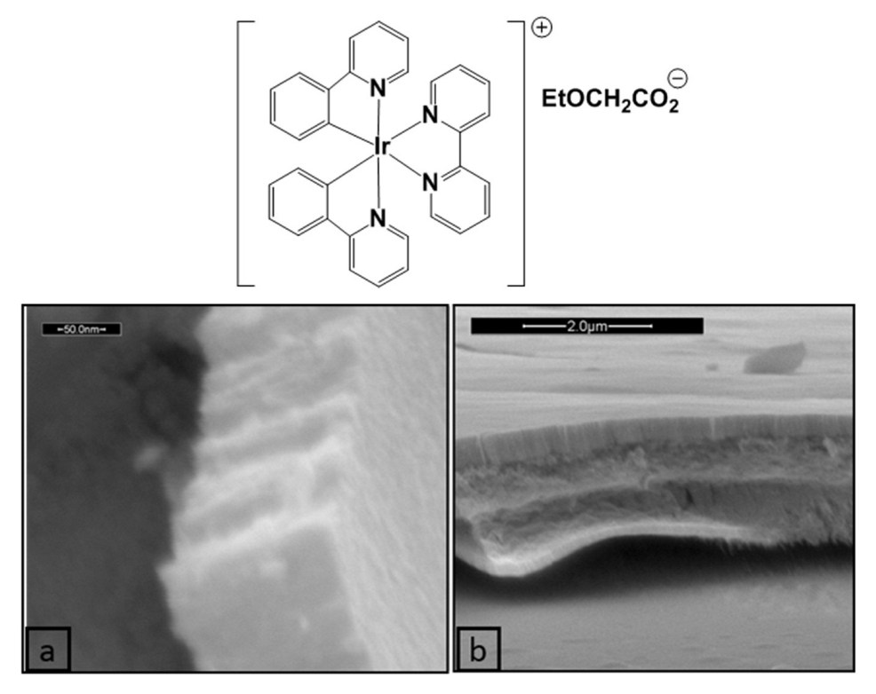
- Scarpelli, F.; Ionescu, A.; Aiello, I.; La Deda, M.; Crispini, A.; Ghedini, M.; Brunelli, E.; Sesti, S.; Godbert, N. High Order in a Self-Assembled Iridium(III) Complex Gelator Towards Nanostructured IrO2 Thin Films. Chem.-Asian J. 2017, 12, 2703–2710. [Google Scholar] [CrossRef] [PubMed]
- Llusar, M.; Sanchez, C. Inorganic and Hybrid Nanofibrous Materials Templated with Organogelators. Chem. Mater. 2008, 20, 782–820. [Google Scholar] [CrossRef]


| Metal Oxide | Work Function (eV) * | Conductivity |
|---|---|---|
| IrO2 | 4.23 [5] | Metallic (ca. 104 S·cm−1) [7] |
| TiO | 4.7 [8] | Metallic (5882 S·cm−1) [9] |
| ReO3 | 6.75 [10] | Metallic (ca.105 S·cm−1) [11] |
| MoO2 | 5.9 [8] | Metallic (3355S·cm−1) [12] |
| RuO2 | 5.2 [13] | Metallic (ca. 1,3.104 S·cm−1) [14] |
| NiO | 6.3 [8] | p-type semiconductor, band gap 4 eV [15] |
| CuO | 5.9 [8] | p-type semiconductor, band gap 1.5 eV [16] |
| Cu2O | 4.9 [8] | p-type semiconductor, band gap 2.40 eV [17] |
| Co3O4 | 6.3 [8] | p-type semiconductor, band gap 2.07eV [18] |
| CoO | 4.6 [8] | p-type semiconductor, band gap 2.6eV [19] |
| Rh2O3 | n.r. ** | p-type semiconductor, band gap 1.4 eV for Rh2O3(I) and 1.2 for Rh2O3(III) [14] |
| TiO2 | 5.4 [8] | n-type semiconductor, band gap anatase 3.2eV, rutile 3.0 eV [20] |
| MoO3 | 6.82 [8] | n-type semiconductor, α-MoO3band gap 3.2 eV [21] |
| WO3 | 6.8 [8] | n-type semiconductor, band gap 2.75 eV [22] |
| SnO2 | 4.75 [23] | n-type semiconductor, band gap 3.6 eV [24] |
| In2O3 | 5.0 [25] | n-type semiconductor, band gap 3.75 eV [26] |
| ZnO | 4.71 [27] | n-type semiconductor, 3.3 eV [28] |
| ZrO2 | 3.1 [29] | insulator |
| V2O5 | 7.0 [30] | insulator-metal transition (275 °C) [6] |
| V2O3 | 4.9 [8] | insulator-metal transition (−111 °C) [31] |
Publisher’s Note: MDPI stays neutral with regard to jurisdictional claims in published maps and institutional affiliations. |
© 2022 by the authors. Licensee MDPI, Basel, Switzerland. This article is an open access article distributed under the terms and conditions of the Creative Commons Attribution (CC BY) license (https://creativecommons.org/licenses/by/4.0/).
Share and Cite
Scarpelli, F.; Godbert, N.; Crispini, A.; Aiello, I. Nanostructured Iridium Oxide: State of the Art. Inorganics 2022, 10, 115. https://doi.org/10.3390/inorganics10080115
Scarpelli F, Godbert N, Crispini A, Aiello I. Nanostructured Iridium Oxide: State of the Art. Inorganics. 2022; 10(8):115. https://doi.org/10.3390/inorganics10080115
Chicago/Turabian StyleScarpelli, Francesca, Nicolas Godbert, Alessandra Crispini, and Iolinda Aiello. 2022. "Nanostructured Iridium Oxide: State of the Art" Inorganics 10, no. 8: 115. https://doi.org/10.3390/inorganics10080115