
Ce0.8Y0.2O2-δ-BaCe0.8Y0.2O3-δ Dual-Phase Hollow Fiber Membranes for Hydrogen Separation

 , , ,
, , ,
Abstract
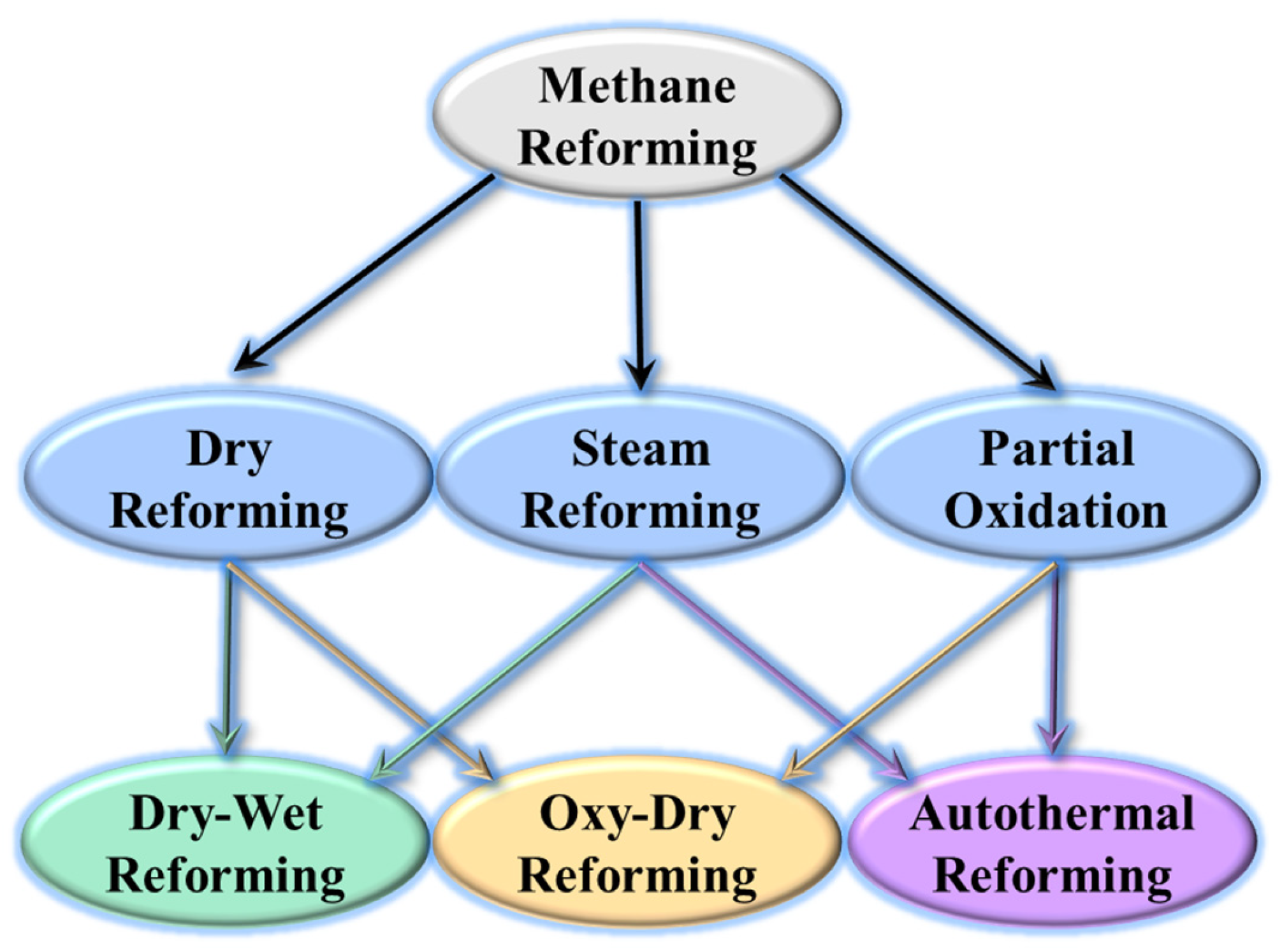
:1. Introduction
2. Experimental Section
2.1. Synthesis of YDC-BCY Dual-Phase Ceramic Powders
2.2. Fabrication of YDC-BCY Dual-Phase HF Membrane
2.3. Characterization
2.4. Hydrogen Permeation Flux of YDC-BCY Dual-Phase HF Membrane
3. Results and Discussion
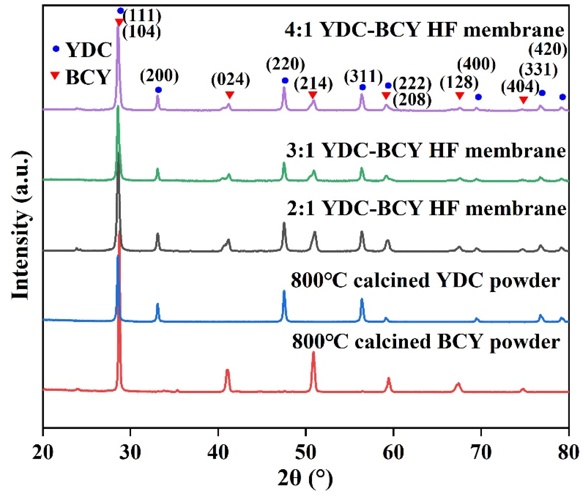
3.1. Crystalline Structure and Morphology of YDC-BCY Dual-Phase Ceramic Powders
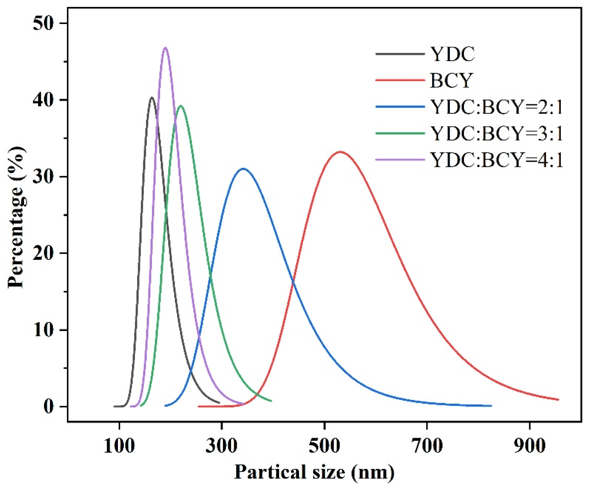
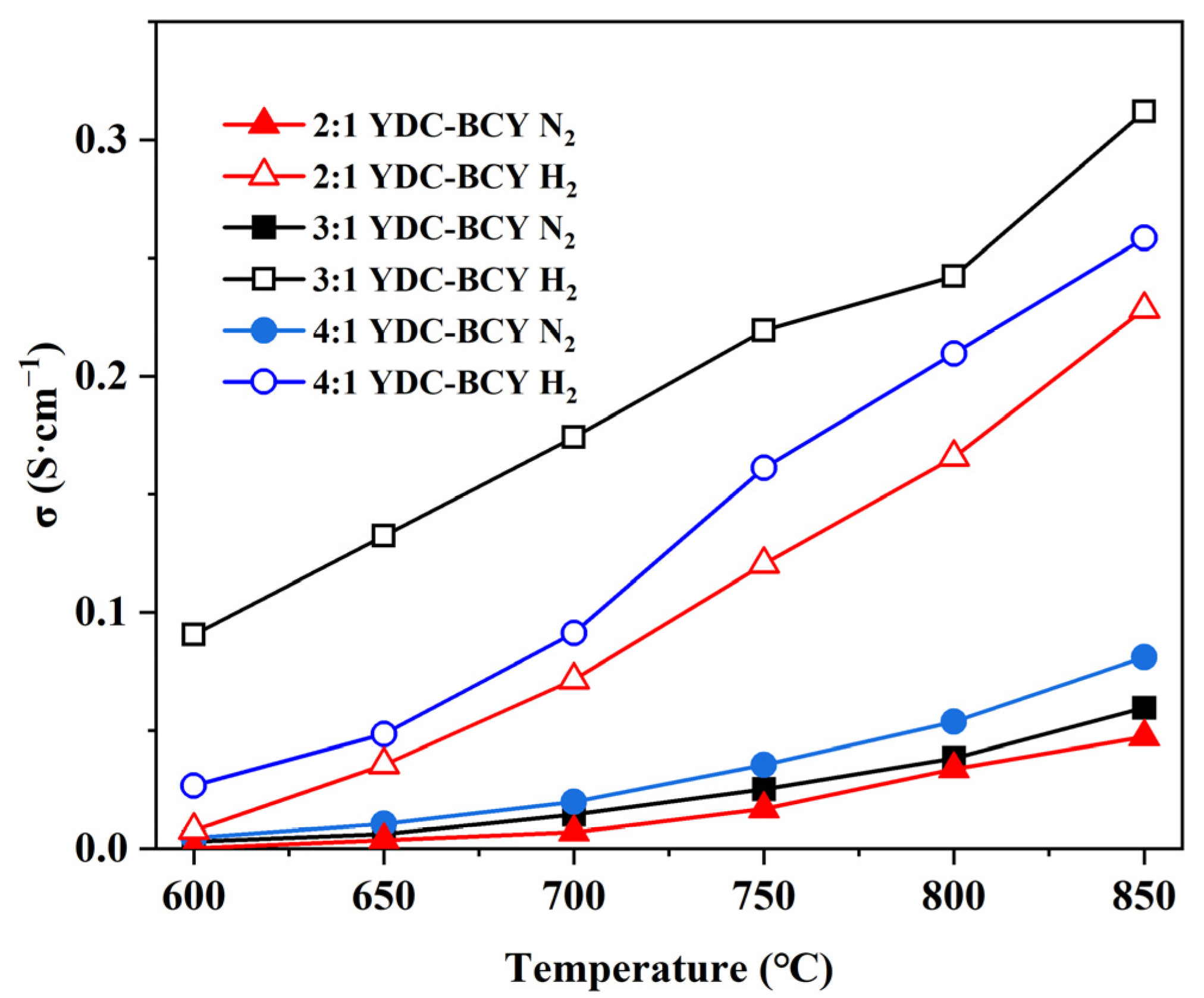
3.2. Particle Size Distributions and Electrical Conductivities of YDC-BCY Dual-Phase Ceramic Powders
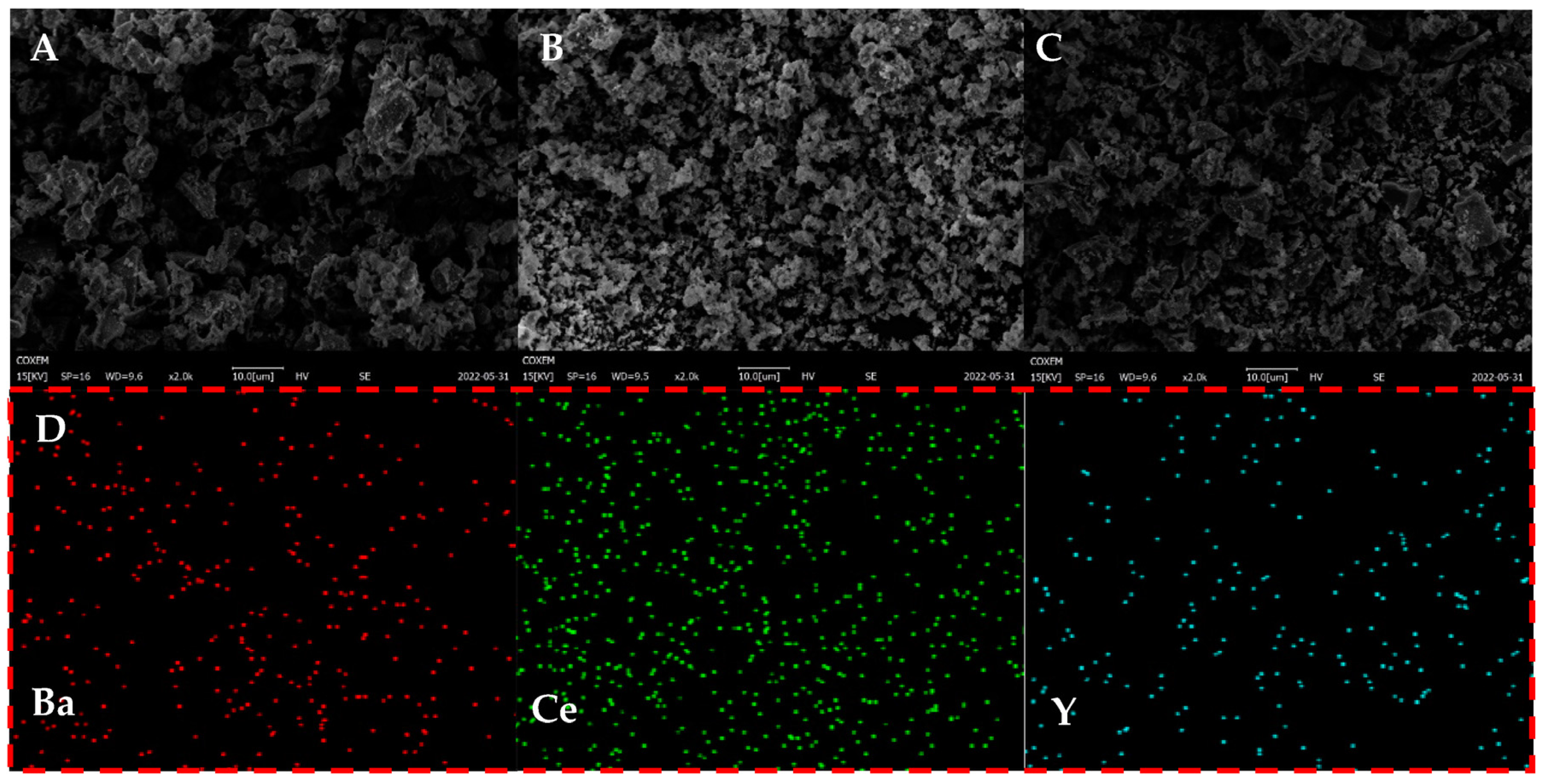
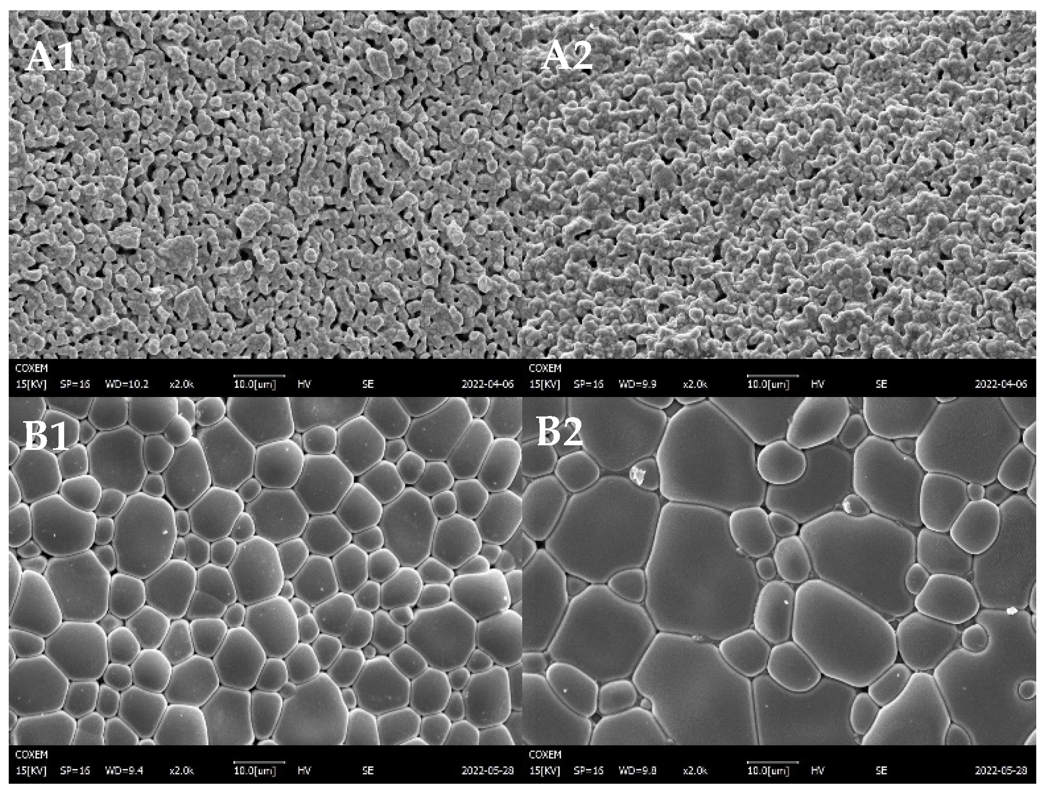
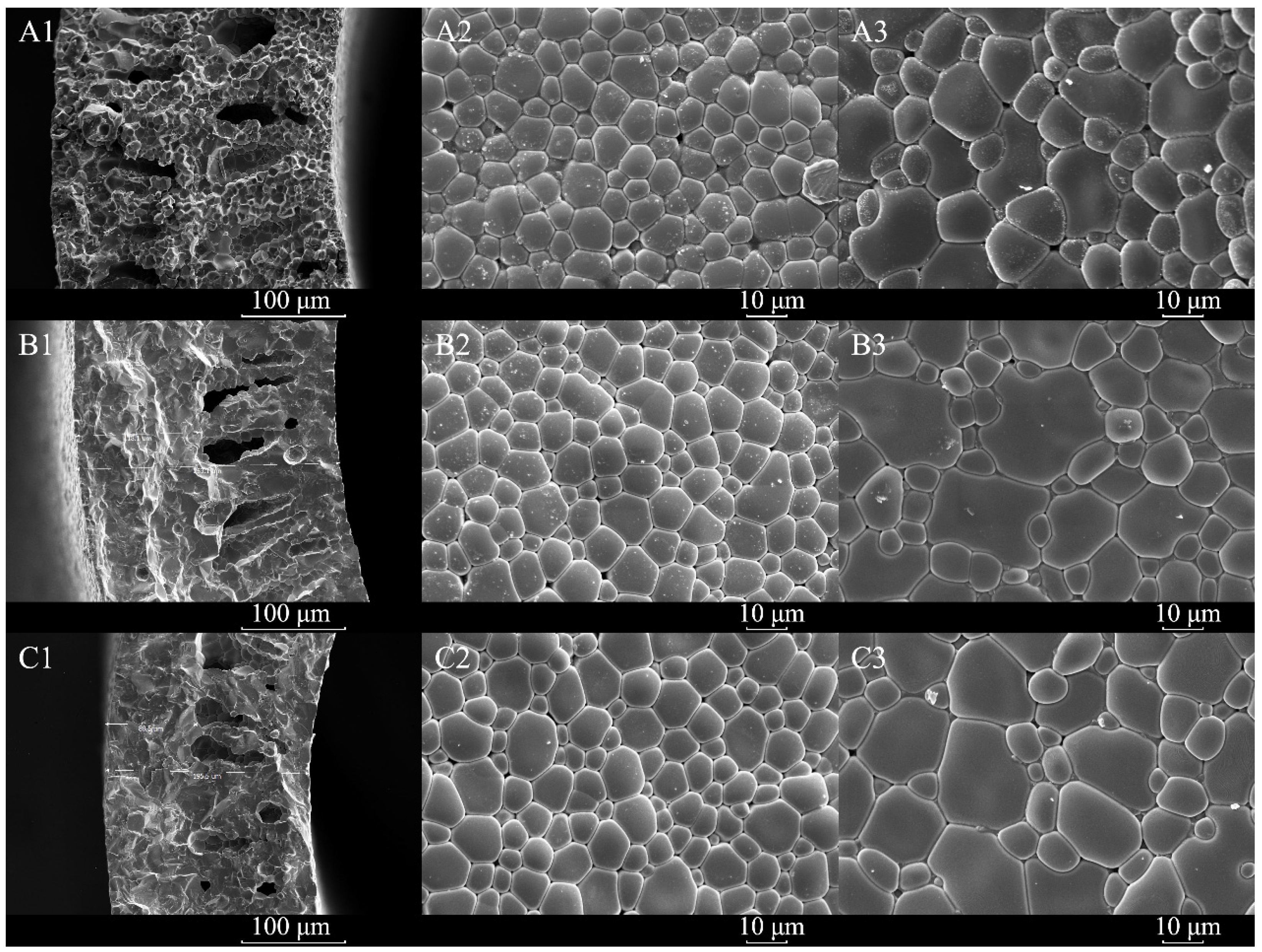
3.3. Morphologies of YDC-BCY Dual-Phase HF Membranes
3.4. Hydrogen Permeation of YDC-BCY Dual-Phase HF Membranes
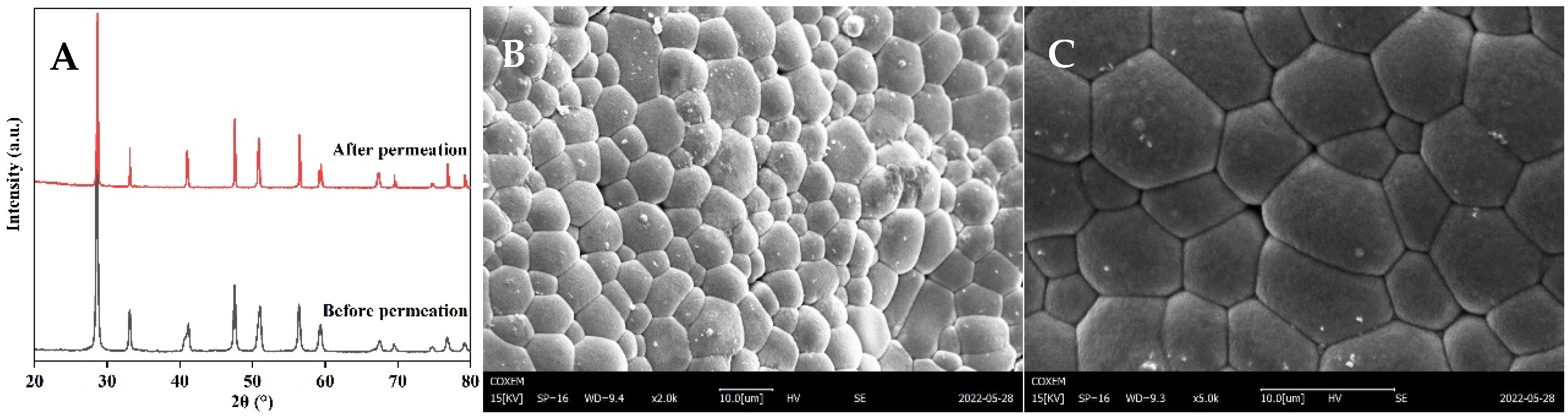
3.5. Post-Test Characterization
4. Conclusions
- YDC and BCY powders with fluorite and perovskite phases, respectively, were successfully synthesized using citric acid-ethylene glycol and glycine as chelating agents, followed by calcination at 900 °C for 5 h.
- The addition of 1.0 wt.% Co2O3 as a sintering additive significantly lowered the sintering temperature, resulting in dense YDC-BCY HF hydrogen-permeable membranes after sintering at 1500 °C for 5 h.
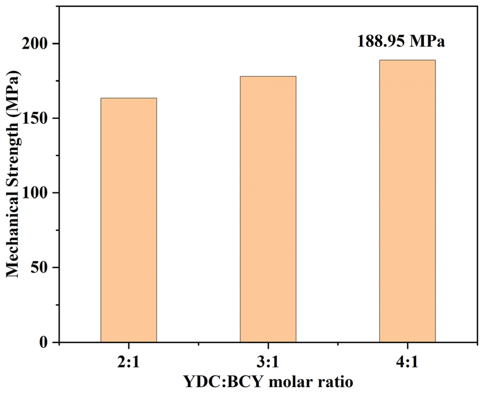
- Temperature, sweep gas, and molar ratio of YDC/BCY had a significant effect on the hydrogen permeation flux of HF membranes. At 1000 °C, the HF membrane with a BCY/YDC molar ratio of 4:1 exhibited the highest hydrogen permeation flux of 0.30 mL min−1 cm−2, which was 1.5 times higher than that of the HF with a BCY/YDC molar ratio of 2:1.
- The hydrogen separation efficiency achieved by a single hydrogen-permeable membrane was limited. In future work, integrating multiple hydrogen-permeable membranes and collecting permeated hydrogen by vacuum could enhance the separation efficiency and purity.
Author Contributions
Funding
Data Availability Statement
Conflicts of Interest
References
- Kim, J.; Sengodan, S.; Kim, S.; Kwon, O.; Bu, Y.; Kim, G. Proton conducting oxides: A review of materials and applications for renewable energy conversion and storage. Renew. Sust. Energ. Rev. 2019, 109, 606–618. [Google Scholar] [CrossRef]
- Xu, H.; Cao, M.; Li, Z.; Li, W.; Meng, S.; Song, H. Production of low carbon number olefins from natural gas: Methane-involved catalytic non-oxidative propane dehydrogenation. Chem. Eng. J. 2023, 454, 140508. [Google Scholar] [CrossRef]
- Olabi, A.G.; Abdelkareem, M.A.; Al-Murisi, M.; Shehata, N.; Alami, A.H.; Radwan, A.; Wilberforce, T.; Chae, K.-J.; Sayed, E.T. Recent progress in Green Ammonia: Production, applications, assessment, barriers, and its role in achieving the sustainable development goals. Energy Convers. Manag. 2023, 277, 116594. [Google Scholar] [CrossRef]
- Suo, Y.; Yao, Y.; Zhang, Y.; Xing, S.; Yuan, Z.-Y. Recent advances in cobalt-based Fischer-Tropsch synthesis catalysts. J. Ind. Eng. Chem. 2022, 115, 92–119. [Google Scholar] [CrossRef]
- Minette, F.; De Wilde, J. Multi-scale modeling and simulation of low-pressure methane bi-reforming using structured catalytic reactors. Chem. Eng. J. 2021, 407, 127218. [Google Scholar] [CrossRef]
- Kumar, N.; Shojaee, M.; Spivey, J.J. Catalytic bi-reforming of methane: From greenhouse gases to syngas. Curr. Opin. Chem. Eng. 2015, 9, 8–15. [Google Scholar] [CrossRef]
- Khademi, M.H.; Alipour-Dehkordi, A.; Tabesh, M. Optimal design of methane tri-reforming reactor to produce proper syngas for Fischer-Tropsch and methanol synthesis processes: A comparative analysis between different side-feeding strategies. Int. J. Hydrogen Energy 2021, 46, 14441–14454. [Google Scholar] [CrossRef]
- Izquierdo, U.; Barrio, V.L.; Requies, J.; Cambra, J.F.; Güemez, M.B.; Arias, P.L. Tri-reforming: A new biogas process for synthesis gas and hydrogen production. Int. J. Hydrogen Energy 2013, 38, 7623–7631. [Google Scholar] [CrossRef]
- Majewski, A.J.; Wood, J. Tri-reforming of methane over Ni@SiO2 catalyst. Int. J. Hydrogen Energy 2014, 39, 12578–12585. [Google Scholar] [CrossRef]
- Alipour-Dehkordi, A.; Khademi, M.H. Use of a micro-porous membrane multi-tubular fixed-bed reactor for tri-reforming of methane to syngas: CO2, H2O or O2 side-feeding. Int. J. Hydrogen Energy 2019, 44, 32066–32079. [Google Scholar] [CrossRef]
- Krenzke, P.T.; Fosheim, J.R.; Zheng, J.; Davidson, J.H. Synthesis gas production via the solar partial oxidation of methane-ceria redox cycle: Conversion, selectivity, and efficiency. Int. J. Hydrogen Energy 2016, 41, 12799–12811. [Google Scholar] [CrossRef]
- Zhang, S.; Li, T.; Wang, B.; Zhou, Z.; Meng, X.; Yang, N.; Zhu, X.; Liu, S. Coupling water splitting and partial oxidation of methane (POM) in Ag modified La0.8Ca0.2Fe0.94O3−δ hollow fiber membrane reactors for co-production of H2 and syngas. J. Membr. Sci. 2022, 659, 120772. [Google Scholar] [CrossRef]
- Gallucci, F.; Fernandez, E.; Corengia, P.; van Sint Annaland, M. Recent advances on membranes and membrane reactors for hydrogen production. Chem. Eng. Sci. 2013, 92, 40–66. [Google Scholar] [CrossRef]
- Wang, H.; Wang, X.; Meng, B.; Tan, X.; Loh, K.S.; Sunarso, J.; Liu, S. Perovskite-based mixed protonic–electronic conducting membranes for hydrogen separation: Recent status and advances. J. Ind. Eng. Chem. 2018, 60, 297–306. [Google Scholar] [CrossRef]
- Bernardo, G.; Araújo, T.; da Silva Lopes, T.; Sousa, J.; Mendes, A. Recent advances in membrane technologies for hydrogen purification. Int. J. Hydrogen Energy 2020, 45, 7313–7338. [Google Scholar] [CrossRef]
- Deibert, W.; Ivanova, M.E.; Baumann, S.; Guillon, O.; Meulenberg, W.A. Ion-conducting ceramic membrane reactors for high-temperature applications. J. Membr. Sci. 2017, 543, 79–97. [Google Scholar] [CrossRef]
- Hashim, S.S.; Somalu, M.R.; Loh, K.S.; Liu, S.; Zhou, W.; Sunarso, J. Perovskite-based proton conducting membranes for hydrogen separation: A review. Int. J. Hydrogen Energy 2018, 43, 15281–15305. [Google Scholar] [CrossRef]
- Ye, K.; Li, K.; Lu, Y.; Guo, Z.; Ni, N.; Liu, H.; Huang, Y.; Ji, H.; Wang, P. An overview of advanced methods for the characterization of oxygen vacancies in materials. TrAC Trends Anal. Chem. 2019, 116, 102–108. [Google Scholar] [CrossRef]
- Mather, G.C.; García-Martín, S.; Benne, D.; Ritter, C.; Amador, U. A-site-cation deficiency in the SrCe0.9Yb0.1O3−δ perovskite: Effects of charge-compensation mechanism on structure and proton conductivity. J. Mater. Chem. 2011, 21, 5764–5773. [Google Scholar] [CrossRef]
- Tan, X.; Tan, X.; Yang, N.; Meng, B.; Zhang, K.; Liu, S. High performance BaCe0.8Y0.2O3−a (BCY) hollow fibre membranes for hydrogen permeation. Ceram. Int. 2014, 40, 3131–3138. [Google Scholar] [CrossRef]
- Zhuang, L.; Li, J.; Xue, J.; Jiang, Z.; Wang, H. Evaluation of hydrogen separation performance of Ni-BaCe0.85Fe0.15O3−δ cermet membranes. Ceram. Int. 2019, 45, 10120–10125. [Google Scholar] [CrossRef]
- Ma, X.; Yang, C.; Chen, H.; Lv, Q.; Sun, K.; Li, W. Hydrogen permeation and chemical stability of Ni–BaCe0.7In0.2Ta0.1O3−δ cermet membrane. Sep. Purif. Technol. 2020, 236, 116276. [Google Scholar] [CrossRef]
- Itagaki, Y.; Hiraoka, A.; Aono, H.; Yahiro, H. Hydrogen permeation of BaCe0.80Y0.20O3−δ-Gd0.1Ce0.9Ox dual-phase membranes. J. Ceram. Soc. Jpn. 2017, 125, 338–342. [Google Scholar] [CrossRef]
- Yang, C.; Ma, X.; Chen, H.; Lv, Q.; Sun, K.; Chen, J.; Yun, S. Chemical stability and hydrogen permeation performance of Ni–BaCe0.7Y0.3–XInO3–δ cermet membranes. J. Alloys Compd. 2018, 762, 409–414. [Google Scholar] [CrossRef]
- Polfus, J.M.; Xing, W.; Fontaine, M.-L.; Denonville, C.; Henriksen, P.P.; Bredesen, R. Hydrogen separation membranes based on dense ceramic composites in the La27W5O55.5–LaCrO3 system. J. Membr. Sci. 2015, 479, 39–45. [Google Scholar] [CrossRef]
- Jia, L.; Liu, M.; Xu, X.; Dong, W.; Jiang, H. Gd-doped ceria enhanced triple-conducting membrane for efficient hydrogen separation. Sep. Purif. Technol. 2021, 256, 117798. [Google Scholar] [CrossRef]
- Zhu, Z.; Hou, J.; He, W.; Liu, W. High-performance Ba(Zr0.1Ce0.7Y0.2)O3−δ asymmetrical ceramic membrane with external short circuit for hydrogen separation. J. Alloys Compd. 2016, 660, 231–234. [Google Scholar] [CrossRef]
- Zhang, K.; Sunarso, J.; Pham, G.H.; Wang, S.; Liu, S. External short circuit-assisted proton conducting ceramic membrane for H2 permeation. Ceram. Int. 2014, 40, 791–797. [Google Scholar] [CrossRef]
- Cheng, H.; Meng, B.; Li, C.; Wang, X.; Meng, X.; Sunarso, J.; Tan, X.; Liu, S. Single-step synthesized dual-layer hollow fiber membrane reactor for on-site hydrogen production through ammonia decomposition. Int. J. Hydrogen Energy 2020, 45, 7423–7432. [Google Scholar] [CrossRef]
- Mercadelli, E.; Gondolini, A.; Montaleone, D.; Pinasco, P.; Escolástico, S.; Serra, J.M.; Sanson, A. Production strategies of asymmetric BaCe0.65Zr0.20Y0.15O3−δ—Ce0.8Gd0.2O2−δ membrane for hydrogen separation. Int. J. Hydrogen Energy 2020, 45, 7468–7478. [Google Scholar] [CrossRef]
- Meng, B.; Wang, H.; Cheng, H.; Wang, X.; Meng, X.; Sunarso, J.; Tan, X.; Liu, S. Hydrogen permeation performance of dual-phase protonic-electronic conducting ceramic membrane with regular and independent transport channels. Sep. Purif. Technol. 2019, 213, 515–523. [Google Scholar] [CrossRef]
- Meng, X.; Shang, Y.; Meng, B.; Yang, N.; Tan, X.; Sunarso, J.; Liu, S. Bi-functional performances of BaCe0.95Tb0.05O3−δ-based hollow fiber membranes for power generation and hydrogen permeation. J. Eur. Ceram. Soc. 2016, 36, 4123–4129. [Google Scholar] [CrossRef]
- Wang, T.; Wang, H.; Meng, X.; Meng, B.; Tan, X.; Sunarso, J.; Liu, S. Enhanced hydrogen permeability and reverse water–gas shift reaction activity via magneli Ti4O7 doping into SrCe0.9Y0.1O3−δ hollow fiber membrane. Int. J. Hydrogen Energy 2017, 42, 12301–12309. [Google Scholar] [CrossRef]
- Wu, Z.; Wang, B.; Li, K. A novel dual-layer ceramic hollow fibre membrane reactor for methane conversion. J. Membr. Sci. 2010, 352, 63–70. [Google Scholar] [CrossRef]
- Shi, Y.; Wang, J.; Li, C.; Song, J.; Meng, B.; Sunarso, J.; Meng, X.; Yang, N.; Tan, X.; Liu, S. High flux and CO2 stable La0.6Ca0.4Co0.2Fe0.8O3−δ hollow fiber membranes through internal coagulation bath optimization. J. Eur. Ceram. Soc. 2023, 43, 5575–5586. [Google Scholar] [CrossRef]
- Meng, B.; Wu, S.; Zhang, S.; Li, C.; Song, J.; Yang, N.; Sunarso, J.; Tan, X.; Wang, M.; Liu, S. CO2-stable and cobalt-free Ce0.8Sm0.2O2−δ-La0.8Ca0.2Al0.3Fe0.7O3−δ dual-phase hollow fiber membranes for oxygen separation. Sep. Purif. Technol. 2022, 300, 121900. [Google Scholar] [CrossRef]
- Song, J.; Wang, Z.; Tan, X.; Cui, Y.; Kawi, S.; Liu, S. Simultaneous hydrogen and oxygen permeation through BaCe0.70Fe0.10Sc0.20O3−δ perovskite hollow fiber membranes. J. Membr. Sci. 2021, 635, 119513. [Google Scholar] [CrossRef]
- Song, J.; Feng, B.; Tan, X.; Han, N.; Sunarso, J.; Liu, S. Oxygen selective perovskite hollow fiber membrane bundles. J. Membr. Sci. 2019, 581, 393–400. [Google Scholar] [CrossRef]
- Rosensteel, W.A.; Ricote, S.; Sullivan, N.P. Hydrogen permeation through dense BaCe0.8Y0.2O3−δ–Ce0.8Y0.2O2−δ composite-ceramic hydrogen separation membranes. Int. J. Hydrogen Energy 2016, 41, 2598–2606. [Google Scholar] [CrossRef]
- Tan, X.; Shen, Z.; Bokhari, A.; Ali, W.; Han, N. Effect of Co2O3 as sintering aid on perovskite BaCe0.8Y0.2O3−δ proton conductive membrane for hydrogen separation. Int. J. Hydrogen Energy 2023, 48, 26551–26558. [Google Scholar] [CrossRef]
- Leng, Z.; Huang, Z.; Zhou, X.; Zhang, B.; Bai, H.; Zhou, J.; Wang, S. The effect of sintering aids on BaCe0.7Zr0.1Y0.1Yb0.1O3−δ as the electrolyte of proton-conducting solid oxide electrolysis cells. Int. J. Hydrogen Energy 2022, 47, 33861–33871. [Google Scholar] [CrossRef]
- Jia, L.; Ashtiani, S.; Liang, F.; He, G.; Jiang, H. Hydrogen permeation through dual-phase ceramic membrane derived from automatic phase-separation of SrCe0.50Fe0.50O3−δ precursor. Int. J. Hydrogen Energy 2020, 45, 4625–4634. [Google Scholar] [CrossRef]
- Unemoto, A.; Kaimai, A.; Sato, K.; Yashiro, K.; Matsumoto, H.; Mizusaki, J.; Amezawa, K.; Kawada, T. Hydrogen permeability and electrical properties in oxide composites✩. Solid State Ion. 2008, 178, 1663–1667. [Google Scholar] [CrossRef]
- Rebollo, E.; Mortalo, C.; Escolastico, S.; Boldrini, S.; Barison, S.; Serra, J.M.; Fabrizio, M. Exceptional hydrogen permeation of all-ceramic composite robust membranes based on BaCe0.65Zr0.20Y0.15O3−δ and Y- or Gd-doped ceria. Energ. Environ. Sci. 2015, 8, 3675–3686. [Google Scholar] [CrossRef]
- Ivanova, M.E.; Escolástico, S.; Balaguer, M.; Palisaitis, J.; Sohn, Y.J.; Meulenberg, W.A.; Guillon, O.; Mayer, J.; Serra, J.M. Hydrogen separation through tailored dual phase membranes with nominal composition BaCe0.8Eu0.2O3−δ:Ce0.8Y0.2O2−δ at intermediate temperatures. Sci. Rep. 2016, 6, 34773. [Google Scholar] [CrossRef] [PubMed]
- Cheng, S.; Wang, Y.; Zhuang, L.; Xue, J.; Wei, Y.; Feldhoff, A.; Caro, J.; Wang, H. A dual-phase ceramic membrane with extremely high H2 permeation flux prepared by autoseparation of a ceramic precursor. Angew. Chem. Int. Ed. 2016, 55, 10895–10898. [Google Scholar] [CrossRef]
- Fish, J.S.; Ricote, S.; O’Hayre, R.; Bonanos, N. Electrical properties and flux performance of composite ceramic hydrogen separation membranes. J. Mater. Chem. A 2015, 3, 5392–5401. [Google Scholar] [CrossRef]
- Escolástico, S.; Solís, C.; Kjølseth, C.; Serra, J.M. Outstanding hydrogen permeation through CO2-stable dual-phase ceramic membranes. Energy Environ. Sci. 2014, 7, 3736–3746. [Google Scholar] [CrossRef]


| Materials | BCY | YDC | ||
|---|---|---|---|---|
| Quantity/mol | Quantity/g | Quantity/mol | Quantity/g | |
| BaNO3 | 0.10 | 26.13 | 0.00 | 0.00 |
| Ce(NO3)3·6H2O | 0.08 | 34.73 | 0.08 | 34.73 |
| Y(NO3)3·6H2O | 0.02 | 7.66 | 0.02 | 7.66 |
| Ethylene glycol | 0.00 | 0.00 | 0.20 | 12.41 |
| Citric acid monohydrate | 0.00 | 0.00 | 0.40 | 84.06 |
| Glycine | 0.40 | 30.03 | 0.00 | 0.00 |
| Water | 5.56 | 100 (mL) | 5.56 | 100 (mL) |
| Ammonia | - | 100 (mL) | - | 100 (mL) |
| Experimental Parameters | Values |
|---|---|
| Composition of the spinning solution (wt.%) | |
| YDC-BCY | 61.54 |
| NMP | 30.77 |
| PESf | 7.69 |
| Extrusion pressure (MPa) | 0.1 |
| Air gap distance (cm) | 0 |
| Spinning suspension flow rate (mL min−1) | 5.0 |
| Internal coagulant flow rate (mL min−1) | 30 |
| Sintering temperature (°C) | 1500, 1550 |
| Dwelling time at sintering temperature (h) | 5 |
| Heating/cooling rate (°C min−1) | 2 |
| Membrane Composition | Thickness (mm) | T (°C) | Feed/Sweep Gas | H2 Flux (mL min−1 cm−2) | Ref. |
|---|---|---|---|---|---|
| Ce0.90Gd0.10O3-δ-SrCe0.95Fe0.05O3-δ-SrFe0.95Ce0.05O3-δ | 0.7 | 940 | 40% H2/wet Ar | 0.54 | [26] |
| SrCe0.95Fe0.05O3-δ-SrCe0.05Fe0.95O3-δ | 0.7 | 900 | 40% H2/wet Ar | 0.33 | [42] |
| SrZrO3-δ-SrFeO3-δ | 1.0 | 900 | H2/wet Ar | 0.048 | [43] |
| BaCe0.65Zr0.2Y0.15O3-δ-Gd0.15Ce0.85O2-δ | 0.65 | 755 | Wet 50% H2/wet Ar | 0.27 | [44] |
| BaCe0.8Eu0.2O3-δ-Ce0.8Y0.2O2-δ | 0.5 | 700 | Dry 50% H2/wet Ar | 0.61 | [45] |
| BaCe0.8Y0.2O3-δ-Ce0.8Y0.2O2-δ | 1.44 | 900 | 10% H2/Ar | 0.0744 | [39] |
| BaCe0.85Fe0.15O3-δ-BaCe0.15Fe0.85O3-δ | 1 | 950 | 50% H2/Ar | 0.76 | [46] |
| BaCe0.2Zr0.7Y0.1O3-δ-Sr0.95Ti0.9Nb0.1O3-δ | 1 | 700 | Wet 50% H2/wet Ar | 0.011 | [47] |
| La5.5WO11.25-δ-La0.87Sr0.13CrO3-δ | 0.37 | 700 | Wet 50% H2/wet Ar | 0.15 | [48] |
| Ce0.8Y0.2O2-δ-BaCe0.8Y0.2O3-δ | 0.2 | 900 | 50% H2/N2 | 0.21 | This work |
Disclaimer/Publisher’s Note: The statements, opinions and data contained in all publications are solely those of the individual author(s) and contributor(s) and not of MDPI and/or the editor(s). MDPI and/or the editor(s) disclaim responsibility for any injury to people or property resulting from any ideas, methods, instructions or products referred to in the content. |
© 2023 by the authors. Licensee MDPI, Basel, Switzerland. This article is an open access article distributed under the terms and conditions of the Creative Commons Attribution (CC BY) license (https://creativecommons.org/licenses/by/4.0/).
Share and Cite
Hei, Y.; Lu, Z.; Li, C.; Song, J.; Meng, B.; Yang, N.; Kawi, S.; Sunarso, J.; Tan, X.; Liu, S. Ce0.8Y0.2O2-δ-BaCe0.8Y0.2O3-δ Dual-Phase Hollow Fiber Membranes for Hydrogen Separation. Inorganics 2023, 11, 360. https://doi.org/10.3390/inorganics11090360
Hei Y, Lu Z, Li C, Song J, Meng B, Yang N, Kawi S, Sunarso J, Tan X, Liu S. Ce0.8Y0.2O2-δ-BaCe0.8Y0.2O3-δ Dual-Phase Hollow Fiber Membranes for Hydrogen Separation. Inorganics. 2023; 11(9):360. https://doi.org/10.3390/inorganics11090360
Chicago/Turabian StyleHei, Yuepeng, Zuojun Lu, Claudia Li, Jian Song, Bo Meng, Naitao Yang, Sibudjing Kawi, Jaka Sunarso, Xiaoyao Tan, and Shaomin Liu. 2023. "Ce0.8Y0.2O2-δ-BaCe0.8Y0.2O3-δ Dual-Phase Hollow Fiber Membranes for Hydrogen Separation" Inorganics 11, no. 9: 360. https://doi.org/10.3390/inorganics11090360