Article

Nitrogen-Doped Carbon Matrix to Optimize Cycling Stability of Lithium Ion Battery Anode from SiOx Materials

1
School of Power & Mechanical Engineering, Wuhan University, Wuhan 430072, China
2
School of Materials Science and Engineering, Hubei University, Wuhan 430060, China
*
Author to whom correspondence should be addressed.
Inorganics 2024, 12(1), 9; https://doi.org/10.3390/inorganics12010009
Submission received: 15 September 2023 / Revised: 4 November 2023 / Accepted: 24 November 2023 / Published: 25 December 2023
(This article belongs to the Special Issue Novel Materials in Li–Ion Batteries)

Abstract

:
This study prepared silicon oxide anode materials with nitrogen-doped carbon matrices (SiOx/C–N) through silicon-containing polyester thermal carbonization. Melamine was introduced as a nitrogen source during the experiment. This nitrogen doping process resulted in a porous structure in the carbon matrices, a fact confirmed by scanning electron microscopy (SEM). Pyridinic and quaternary nitrogen, but mainly tertiary nitrogen, were generated, as shown via X-ray photoelectron spectroscopy (XPS). Electrochemical tests confirmed that, as anode materials for a lithium-ion battery, SiOx/C–N provided better cycle stability, improved rate capability, and lower Li+ diffusion resistance. The best performance showed an activated capacity at 493.5 mAh/g, preserved at 432.8 mAh/g after the 100th cycle, with 87.7% total Columbic efficiency. Those without nitrogen doping gave 1126.7 mAh/g, 249.0 mAh/g, and 22.1%, respectively. The most noteworthy point was that, after 100 cycles, anodes without nitrogen doping were pulverized into fine powders (SEM); meanwhile, in the case of anodes with nitrogen doping, powders of a larger size (0.5–1.0 µm) formed, with the accumulation of surrounding cavities. We suggest that the formation of more prominent powders may have resulted from the more substantial nitrogen-doped carbon matrices, which prevented the anode from further breaking down to a smaller size. The volume expansion stress decreased when the powders decreased to nanosize, which is why the nanosized silicon anode materials showed better cycling stability. When the anodes were cracked into powders with a determined diameter, the stress from volume expansion decreased to a level at which the powders could preserve their shape, and the breakage of the powders was stopped. Hence, the diameters of the final reserved powders are contingent on the strength of the matrix. As reported, nitrogen-doped carbon matrices are more robust than those not doped with nitrogen. Thus, in our research, anodes with nitrogen-doped carbon matrices presented more large-diameter powders, as SEM confirmed. Anodes with nitrogen doping will not be further broken at a larger diameter. At this point, the SEI film will not show continuous breakage and formation compared to the anode without doping. This was validated by the lower deposition content of the SEI-film-related elements (phosphorous and fluorine) in the cycled anodes with nitrogen doping. The anode without nitrogen doping presented higher content, meaning that the SEI films were broken many times during lithiation/delithiation (EDS mapping).

Graphical Abstract

1. Introduction

Optimizing anode materials is a crucial goal of the current research in the pursuit of better performance for lithium-ion batteries (LIBs). Among those materials, Si-based ma terials are regarded as the most promising substitutes for carbon due to their low discharge potential and high theoretical specific capacity (4200 mAh/g) [1]. The main obstacle to the commercial application of Si-based materials is the volume variation during the lithiation/delithiation procedure (300–400% expansion when lithiated). This volume expansion results in particle cracking, anode pulverization, and the loss of electrical contact between the active material and the current collector. Consequently, this leads to poor reversibility and rapid capacity fading, especially at high current densities [2,3]. Compared with elemental Si anode materials, silicon oxides (SiOx, 0< x < 2) are also considered as silicon-based anode materials due to their abundant reserves, low cost, easy synthesis, and minor volume change (approximately 200%, even with a relatively lower specific capacity (∼1600 mAh/g)) [4]. The superior performance of SiOx can be attributed to the high strength of the Si–O chemical bond (twice the strength of the Si–Si bond) and the formation of electrochemically inert materials such as Li2O and Li4SiO4. These materials effectively resist volume expansion. However, SiOx anode materials suffer from poor electronic conductivity and a low first Coulomb conversion rate due to the irreversible electrochemical reaction between Li+ and the SiO2 matrix. Similar to elemental silicon, the main shortcoming is volume expansion [5].
There are two practical methods to solve this problem. One is adopting nanosized powders to elevate the stress resulting from volume expansion [6]. Nanostructures exhibit better resistance to fracturing compared to their bulk counterparts, resulting in significantly improved electrochemical kinetics for lower volume expansion stress. Various nanostructures have been developed, including nanoparticles, nanofibers, nanowires and nanotubes, thin films, and porous nanostructures. Among these, Si nanoparticles are the most used and the only commercially applied materials due to their ability to resist cracking/deformation during cycling. However, nanoparticles also need a carbon matrix to buffer the volume expansion. Another technique is adopting matrices to buffer the volume expansion of silicon anodes, among which carbon matrices are mostly industrially used. Recently, the heteroatom (such as N, S, P, O)-doping modification of carbon matrices has been proven to improve their performance [7]. Nitrogen-doped carbon matrices are the most often used due to their high conductivity and fast electron transfer; moreover, the defect structure can also facilitate lithium-ion storage and the wetting of electrolytes to an electrode. Melamine is the nitrogen resource generally used. Jing et al. reported that excellent lithium-ion diffusion could be achieved due to the generation of Li3N solid electrolytes stemming from melamine involvement [8]. Xie et al. reported that a well-designed structure favors N–SiOx/C@C, ensuring a conductive path and structural integrity during the cycle [9]. Nitrogen-doped carbon matrices are also advantageous in maintaining the mechanical integrity of anodes [10]. For example, due to the improved conductivity of the mixture, N–C-type composites have been shown to offer a high capacity and good cycling stability as anodes for lithium–sulfur batteries [11]. As Qu et al. reported, an LIB anode based on ZnO/Co3Zn in nitrogen-doped carbon matrices displayed remarkable lithium storage properties (1162.4 mAh/g, after 300 cycles under 0.2 A/g, ~533.8 and 473.3 mAh/g under 0.5 and 1.0 A/g) [12]. Choi et al. also described a simple and inexpensive method to coat nano Si powders with nitrogen and carbon, showing outstanding electrochemical performance [13].
In this study, we prepare a SiOx anode with nitrogen-doped carbon matrices (SiOx/C–N) from the thermal carbonization of silicon-containing polyesters, with cheap and readily available melamine as a nitrogen source. Building on our experience, reduced graphene oxides (rGO) are also incorporated to enhance the materials (Scheme 1) [14,15]. According to the literature, ultrathin graphene sheets serve as a barrier to hinder the aggregation of nanoparticles; their porous graphene sheets can provide a void space against volume changes. Additionally, graphene sheets are active materials for additional Li+ storage. Furthermore, the nanoparticles are anchored on the surfaces of the graphene sheets, contributing to high rate performance. Thus, anode nanocomposites with graphene can feature a large reversible specific capacity, long cycling life, and good rate capability [6].
After nitrogen doping, the cycling stability and rate performance are significantly improved. As anode materials, the best capacity retention rate is 87.7% after 100 cycles at a current density of 0.1 C, considerably higher than that without nitrogen doping. Further, the nitrogen-doped anodes form powders with diameters of 0.5–1.0 µm during the lithiation/delithiation procedure. The discussion revolves around the rationale behind the enhancement in cycling stability.

2. Results and Discussion

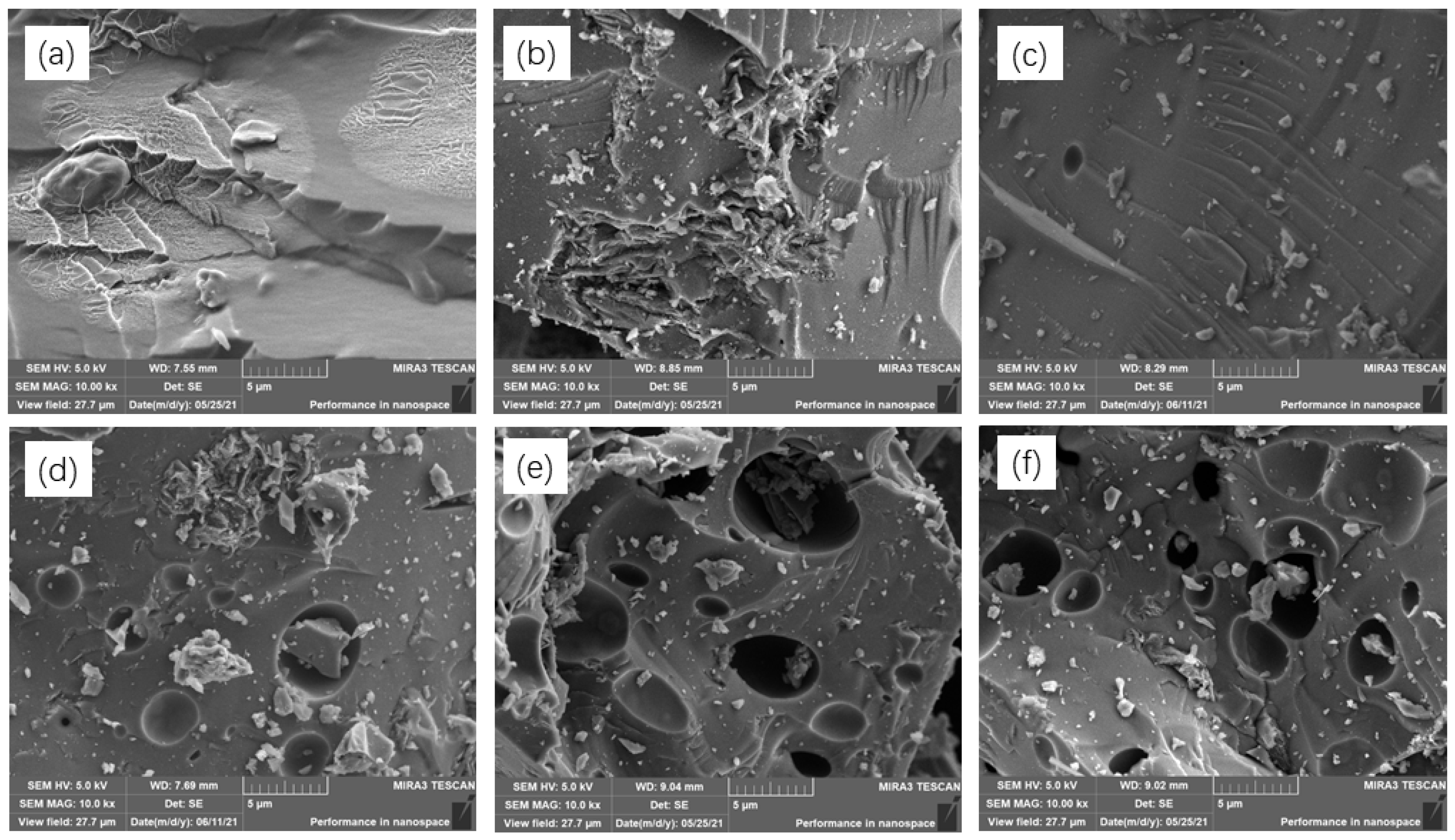
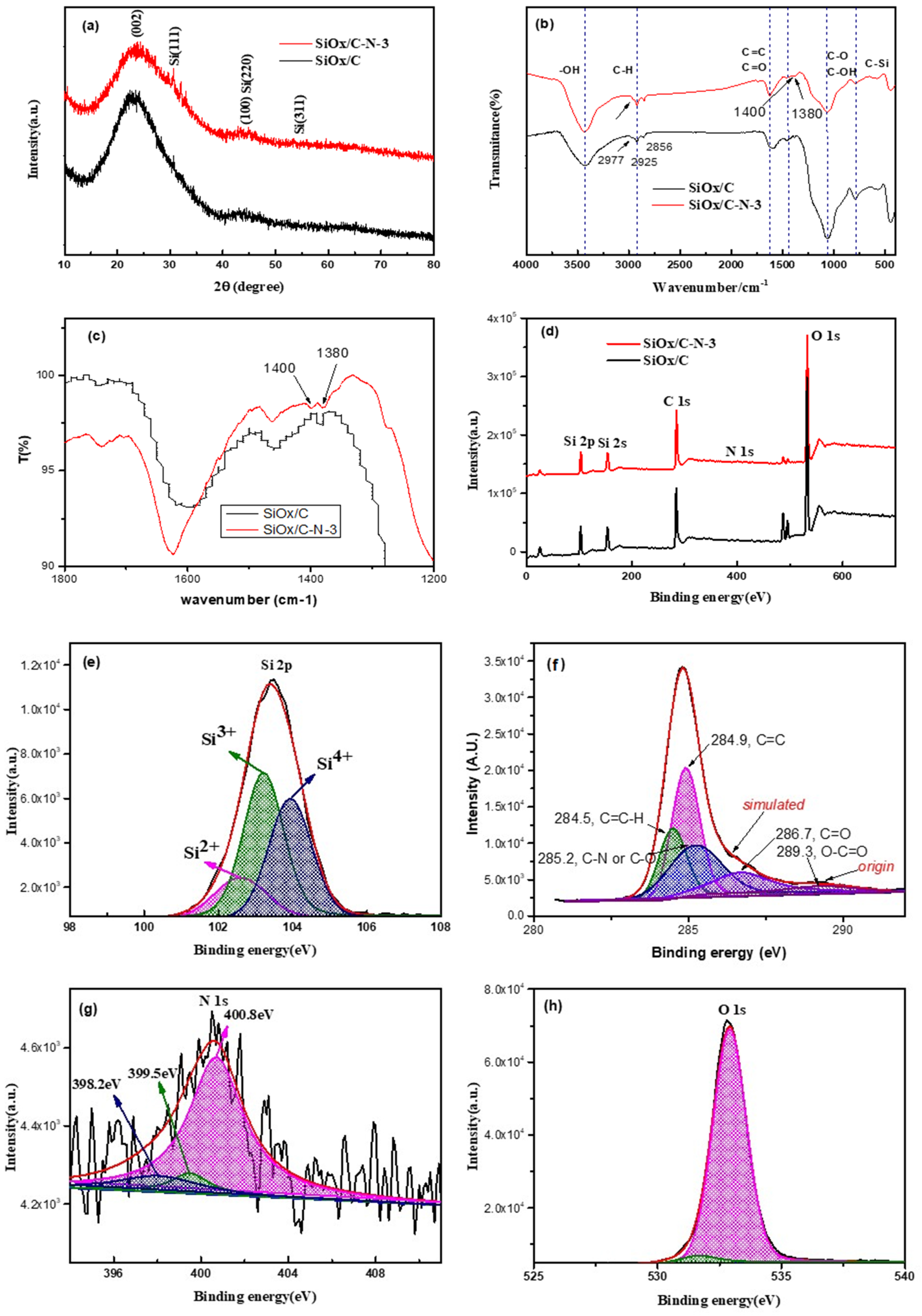
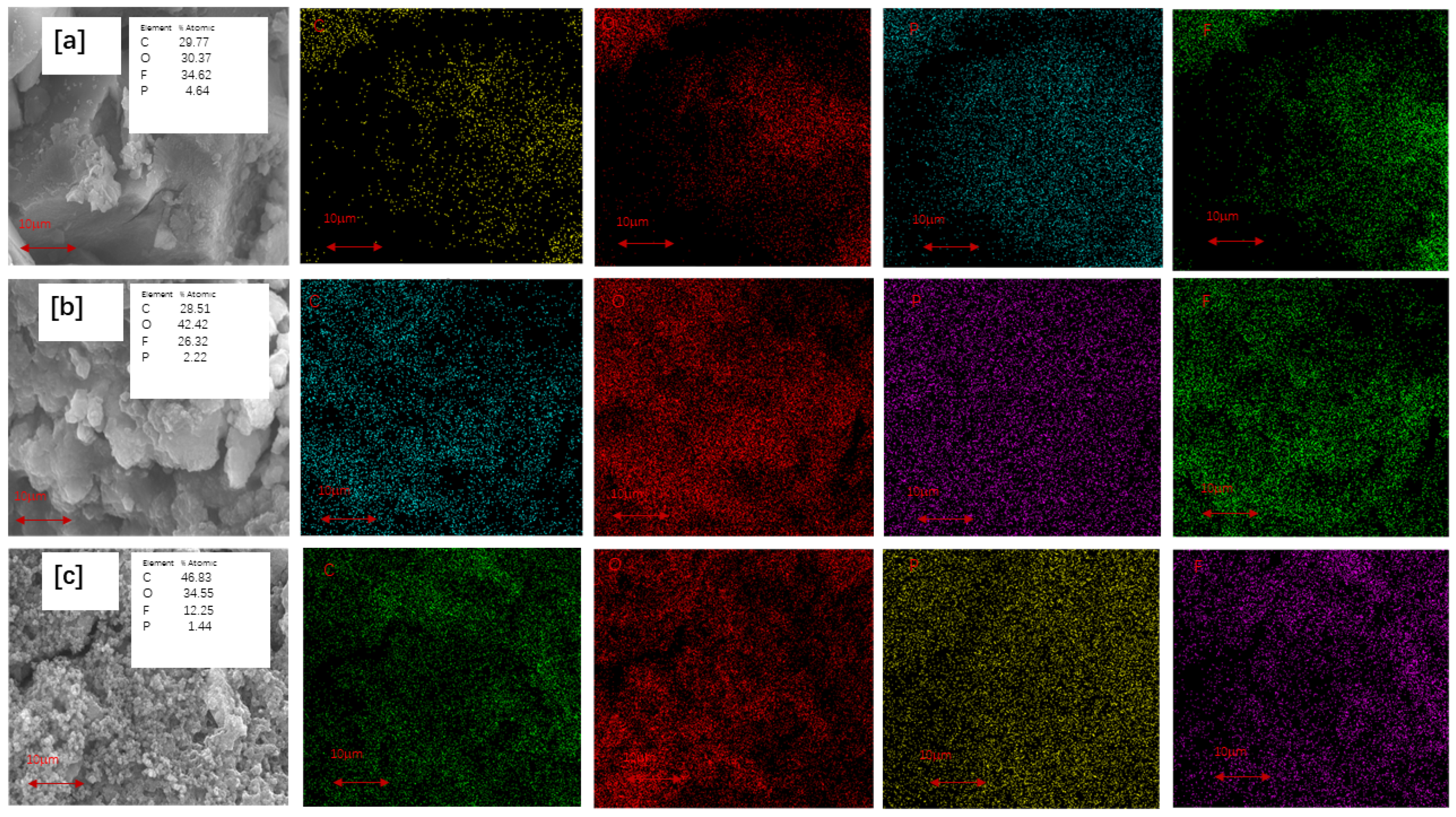
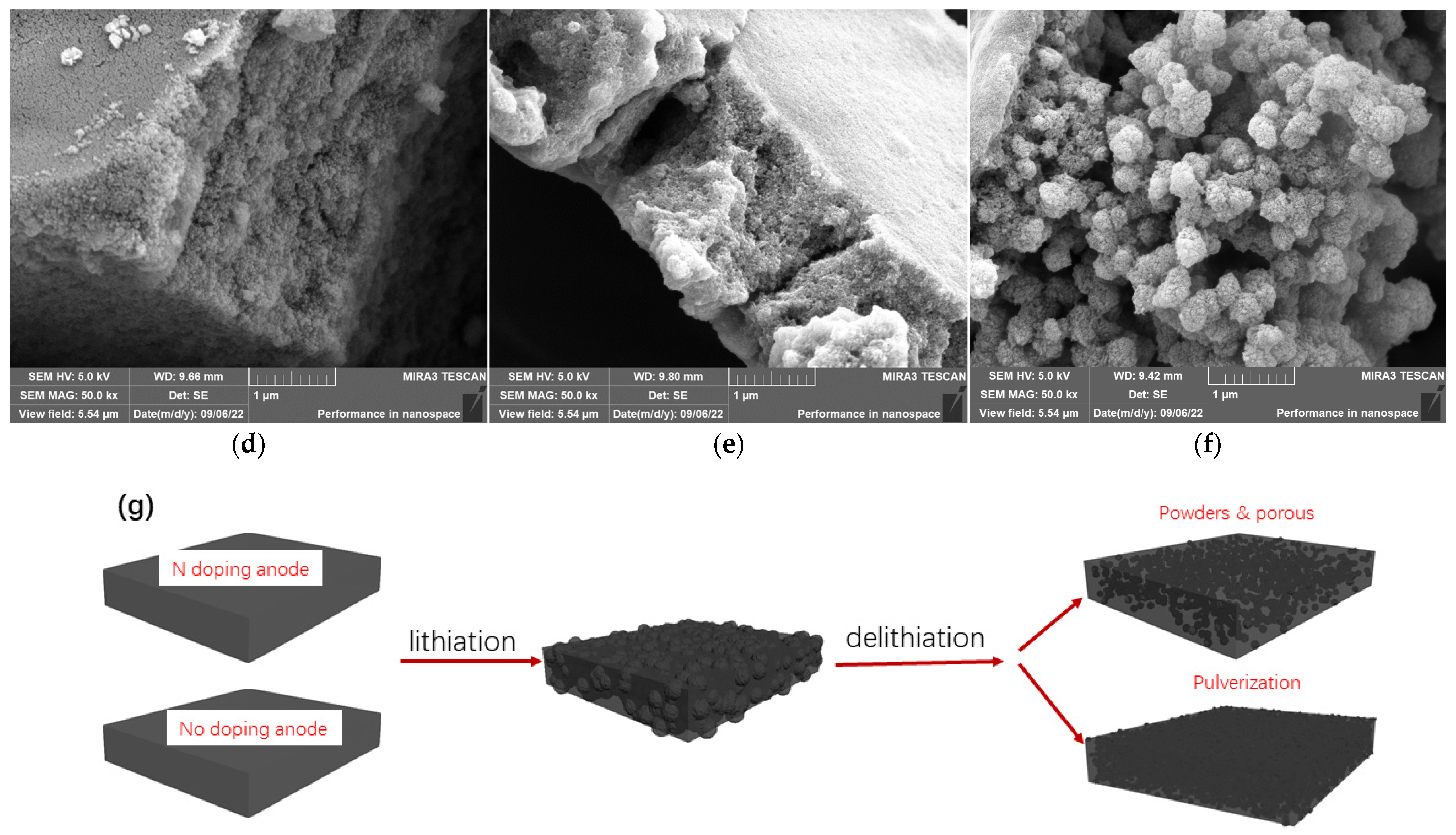
2.1. Structure Characterization

Figure 1 presents the SEM of SiOx/C–N–1 and SiOx/C–Ns. SiOx/C and SiOx/C–N–1~2, which contained no or lower nitrogen elemental content, showed no cavities. However, from Figure 1d–f, showing SiOx/C–N–3~5, some micro-porosity can be observed, possibly due to the evaporation of melamine during carbonization. Table 1 gives the nitrogen content of SiOx/C–N–1, SiOx/C–N–3, and SiOx/C–N–5 from EDS mapping. It is concluded that the nitrogen content increases with the feed ratio of melamine.
Figure 2 presents the spectrum information to enable a further understanding of the structure of SiOx/C–Ns. From Figure 2a, the X-ray diffraction (XRD) results of SiOx/C and SiOx/C–N–3 show few differences. The broad peaks at ~23–25° can be assigned to silicon oxides or carbon crystalline (the latter is accompanied by a rise at 43°). No prominent peaks related to monoatomic Si crystalline can be observed (28.4°, 47.4°, and 56.2°, for Si (111), Si (220), and Si (311), respectively [16]). This means that no silicon oxides were reduced to elemental silicon during carbonization.
The FTIR spectra in Figure 2b are also similar to the XRD results. The minor difference is that, for SiOx/C, only one peak is observed at about 1385 cm−1. Meanwhile, for SiOx/C–N–3, there are two peaks at 1400 and 1380 cm−1 (clearly observed in Figure 2c at a higher resolution). The absorption at 1380 cm−1 and 1400 cm−1 can be assigned to C–N, confirming nitrogen’s existence [17]. The vibration absorption of N–H and O–H at 3700–3300 cm−1, as well as that of C=O at 1630 cm−1, accompanied by that for Si–O–Si and C–O at 1000–1100 cm−1, can be easily found, indicating that the materials are not pure carbon or silicon but are doped with oxides and nitrogen [18].
Further, XPS spectra were adopted to verify the nitrogen and its bonding methods. As seen in Figure 2d, peaks of C1s (284–290 eV), O1s (~530 eV), N1s (~400 eV), and Si2p (103eV)/Si2s (155 eV) are identified. Those at 500eV can be assigned to Sn and added as vulcanization accelerants for silicon-containing polyesters. The Gaussian fitting for Si2p, C1s, N1s, and O1s is also presented (Figure 2e–h). The C1s peak can be deconvoluted into C–H (284.5 eV), C=C (284.9 eV), C–O and C–N (285.2 eV), C=O (286.7 eV), O–C=O (289.3 eV), suggesting the presence of residual of carbonyl, ester, and ether groups [19,20]. Regarding the low nitrogen content, it is suggested that the C1s peak related to tertiary nitrogen (C–N, 285.5 eV [21]) might be shielded by that of C–O. Although the N1s peak is considerably weak due to its low content and sensitivity factor [22], the peaks for pyridinic N (398.2 eV), quaternary nitrogen (399.5 eV), and tertiary nitrogen (400.8 eV) at the basal plane can be found in Figure 2e. In agreement with the literature, most of them are the most thermally stable tertiary nitrogen [21,23]. No Si3N4 binding energy (397.6 eV) was obtained, as its formation needs a higher temperature (>1400 °C) [24]. The Si2p peaks at 103.8 eV, 102.8 eV, 102.1 eV, and 101.3 eV can be assigned to silicon oxides, Si4+, Si3+, Si2+, and Si+, respectively [25,26]. No binding energy corresponding to monoatomic silicon (98.2 eV) was obtained, in agreement with the XRD spectra.

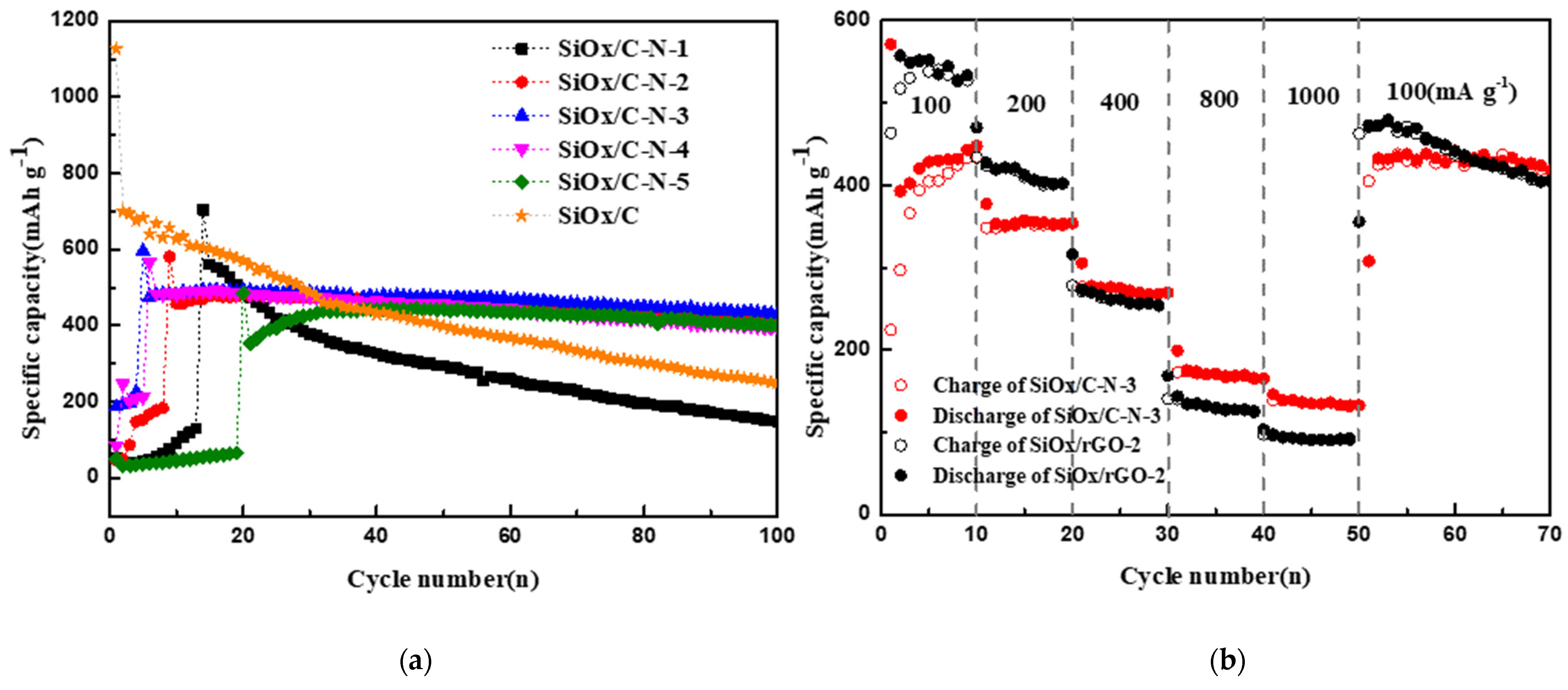
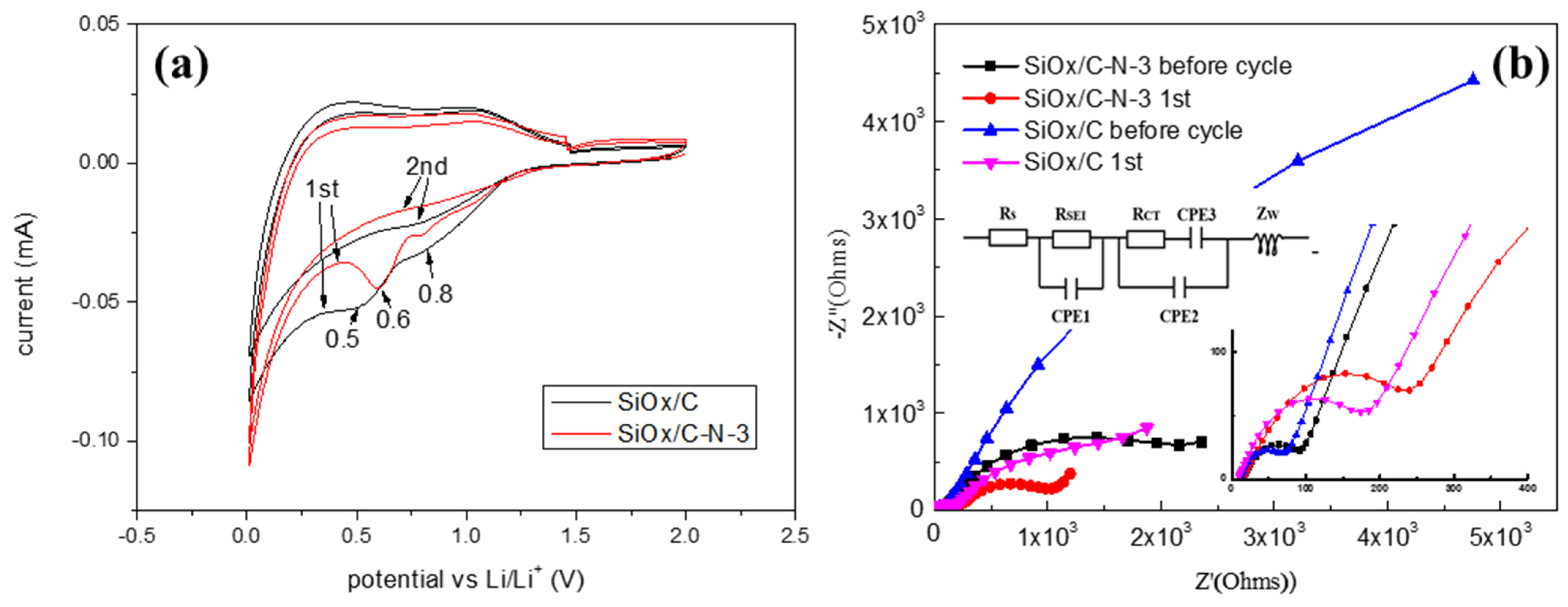
2.2. Electrochemical Performance Affected by Nitrogen Component

Figure 3 presents the electrochemical performance of the LIB anode from SiOx/c and SiOx/C–Ns. As seen in Figure 3a, anodes with SiOx/C–Ns give activation periods within <20 cycles, depending on the melamine feed ratios. The capacities before activation are considerably low. However, SiOx/C does not show an activation period. The activation during charging/discharging is usually related to the nitrogen component [27]. Interestingly, the nitrogen component in composites improves the cycle stability and rate performance. As shown in Table 2, the best electrochemical performance is given by SiOx/C–N–3, which presents an activated capacity of 493.5 mAh/g that is maintained at 432.8 mAh/g after the 100th cycle, with 87.7% total Columbic efficiency. SiOx/C gives a first capacity at 1126.7 mAh/g and a 100th capacity at 249.0 mAh/g, with 22.1% total Columbic efficiency. The cycle stability of SiOx/C–N–1 is similar to that of SiOx/C, which may result from the low nitrogen content. It is possible that a higher melamine feed ratio results in lower capacities, as indicated in Table 2.
In Figure 3b, the rate performance of anodes from SiOx/C–N–3 (the best materials among SiOx/C–Ns) and SiOx/C is presented; the specific charging currents were sequentially 100, 200, 400, and 800 mA/g, and then back to 100 mA/g. It is clear that even SiOx/C–N–3 shows lower capacities than SiOx/C at 100 and 200 mA/g, but it gives higher capacities at higher currents, namely 400 to 1000 mA/g. At the end of each current, the capacities of SiOx/C–N–3 are 434.4 mAh/g, 353.5 mAh/g, 269.4 mAh/g, 164.8 mAh/g, and 132.4 mAh/g, respectively, while those of SiOx/C are 433.4 mAh/g, 277.8 mAh/g, 140.4 mAh/g, 96.8 mAh/g, and 91.6 mAh/g, respectively. This means that nitrogen-doped carbon matrices support faster charging. The recovery performance of the two materials is similar: when the setting currents decrease to 100 mA/g, their capacities increase to the level of the 10th cycle, namely 405 mAh/g and 470.3 mAh/g, respectively.
Figure 4 presents the cyclic voltammetry curves of SiOx/C–N–3 and SiOx/C and their Nyquist plots. There is no obvious anode observed, except two cathode peaks at 0.5 V for SiOx/C and 0.6 V for SiOx/C–N–3 (Figure 4a) [28]. The anodic peaks at 0.32 and 0.51 V (delithiation of Li–Si phases, accompanied by the formation of amorphous Si) and the cathodic peak at ~0.2 V at subsequent cycles (lithiation of amorphous Si) [29,30] cannot be observed for both materials, confirming no monoatomic silicon, in agreement with the XRD and XPS results (Figure 3). This means that adding melamine does not change the chemical structure of the silicon component; otherwise, lithiation/delithiation will present a new electrochemical reaction. The cathodic peak for SiOx/C at 0.5 V usually results from the lithiation of amorphous silicon oxides [15], but here it disappeared in the second cycle, which means that this peak was not reported. We assigned it to the irreversible electrochemical reactions of lithium ions with active materials related to the SEI film formation. After melamine is added, the peak moves to a high potential, 0.6 V. These two peaks are usually associated with SEI film formation. From Figure 4a, after melamine is added, the peak becomes sharper, probably indicating a stronger SEI film, as the sharper peaks mean that more chemicals are generated.
The Nyquist plots of the anodes are presented in Figure 4b. All Nyquist plots demonstrate a semicircle in the high-frequency region and a straight line in the low-frequency region. The former corresponds to charge transfer resistance (Rct) and/or resistance from the SEI layer (RSEI), while the latter reflects Li+ diffusion resistance in the electrode [31,32]. After the first cycle, Rct/RSEI increases, attributed to the formation of the SEI film [33]. However, the Li+ diffusion resistance decreases after the first cycle due to the activation of the materials. As Zou et al. noted, the presence of the quaternary nitrogen bond can facilitate electron transfer and cause an enhancement in the conductivity of carbon materials; the presence of pyrrolic nitrogen is assumed to increase the capacitance performance of the electrode [7]. Chen et al. explained that the decrease in Li+ diffusion resistance is due to the slow wetting of electrolytes in porous electrodes and the increased electrical conductivity of silicon during the charge/discharge processes [34]. The charge transfer resistance (Rct/RSEI) of SiOx/C before and after the first cycle is much lower than that of SiOx/C–N–3, while the Li+ diffusion resistance is higher. The lower Li+ diffusion resistance is meaningful given the poor electrical conductivity of silicon anodes, which usually hinders its industrial application [35]. The higher Rct/RSEI of SiOx/C–N–3 might result from the nitrogen component influencing the regular carbon arrangement for the existing pyrrolic and quaternary nitrogen, as the XPS spectra in Figure 2e confirm. The lower Li+ diffusion resistance of SiOx/C–N–3 can be assigned to the porous structure, as Figure 1 presents.
Further, SEM graphs of the cycled anodes containing SiOx/C, SiOx/C–N–3, or SiOx/C–N–5 are adopted to identify the differences in microstructure development during the lithiation/delithiation procedure (Figure 5). After the 100th cycle, the cells were disassembled. The anodes, without further treatment except ethanol washing to remove electrolytes, were photographed with SEM. As shown in Figure 5, the surfaces of anodes containing SiOx/C were cracked, but those of anodes containing SiOx/C–N–5 were not. Surprisingly, the inner parts under the anode surface differed considerably. The internal anode from SiOx/C–N–5 was granulated (powders with diameters of about 0.5–1.0 µm) and formed accumulating cavities. As reported, nanoporous silicon shows good performance in liquid LIBs, providing a buffer that effectively alleviates the significant volume change of the silicon anode [36]. The surrounding cavities will buffer volume variation and improve the cycling stability (Figure 3). This is significantly different from that of the anode from SiOx/C, which is pulverized, or, in other words, the anode without nitrogen doping presents powders with much smaller sizes.
We suggest that the volume expansion and contraction of the anodes formed powders with larger sizes (Figure 5g). Volume expansion and contraction usually lead to the breakage of anodes [2,3]; thus, the anodes were expanded and contracted and became powders. As reported, smaller diameters induce lower volume variation stress [6], which is why nanosized silicon offers better cycling stability. We supposed that when the powder size was reduced to a determined diameter, the stress from volume expansion was decreased to a level at which the powders could preserve their shape, and the breakage of the powders was stopped. Based on this, the diameters of the final reserved powders will depend on the strength of the matrices. Powders will show ongoing cracking at a larger diameter if the matrices are stronger. On the other hand, stronger matrices can resist higher stress and prevent more significant powders from cracking. Correspondingly, a weak matrix resists lower stress and leads to smaller powders. As reported [37], nitrogen-doped carbon matrices are stronger than those that are not. Thus, in this research, the anodes with nitrogen-doped carbon matrices presented larger-diameter powders, as the SEM confirmed (Figure 6a).
Based on our results, anodes with nitrogen doping will not be broken at a greater diameter, and the SEI film will be stable. The number of times that the SEI film was broken can be evaluated using the deposition content of some related elements in the anode. If the SEI film was broken many times, the content of these elementals would be relatively higher. This research adopted a LiPF6/EC/EMC electrolyte, which can generate an SEI film containing LiCO3, ROCOOLi, ROLi, RCOOLi, LiF, LixPFy, and LixPOyFz, etc. Usually, phosphorus and fluorine are regarded as SEI-film-related elements [14,38].
The anode was disassembled to identify the elemental content, and the elemental composition was precisely obtained from EDS mapping, as shown in Figure 6. To avoid the disturbance of residual LiPF6 in the electrolyte, the disassembled anodes were immersed in ethanol to remove the LiPF6 solution completely before SEM graphing. Thus, the detected phosphorus and fluorine elements of the cycled anodes could only result from the broken SEI film. As Figure 6a–c show, the phosphorus and fluorine content decrease when more melamine is added. This confirms that, as expected, the SEI films become more stable after nitrogen doping.

3. Materials

The graphene oxides (GO, >99.9%) used were commercial products. Trimethoxysilane (industrial purity) was purchased from Hubei Wuda Silica New Material Co., Ltd., Wuhan, China. Ethylene glycol (C2H6O2, 99.0 wt%), phthalic anhydride (C8H4O3, 99.7 wt%), melamine, ammonia (NH3·H2O, 25.0~28.07 wt%), Tin(II) chloride dihydrate (SnCl2·2H2O, 98.0 wt%), and ethanol absolute (C2H6O, 99.7 wt%) were purchased from Sinopharm Group Chemical Reagent Co., Ltd., Shanghai, China.

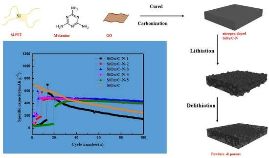
3.1. Synthesis of SiOx/C–Ns

The preparation of SiOx/C–N through a straightforward solution blending process is outlined in Scheme 1 [14,15]. Initially, ethylene glycol (40.0 g) and a slight excess of phthalic anhydride (100.0 g) were esterified at 120 °C. Subsequently, trimethoxysilane (80.0 g) was added with stirring. After 30 min, deionized water (20.0 g) was gradually introduced within 10 min. Following an additional 30 min of stirring, the generated volatiles were evaporated to yield silicon-containing polyesters.
Then, 0.08 g of graphene oxide (rGO) was added to 4.0 g of deionized water and then ultrasonically dispersed for 15 min. A few drops of ammonia were added to obtain a uniformly distributed graphene oxide aqueous solution.
Next, 20 g of the synthesized silicon-containing polyesters and different weights of melamine were mixed, and 1.0 g of deionized water was added. Following this, the above rGO solution was slowly dropped and ultrasonicated for 30 min. Tin (II) chloride dihydrate was added as a curing accelerator; then, the mixed solution was exposed to air for room-temperature curing.
After about 24 h, the cured material was thermally carbonized at 750 °C (with a heating rate of 5 °C/min) under an argon atmosphere for 2 h. The temperature-increasing rate was 5 °C/min. The resulting samples were labeled as SiOx/C–Ns up to the melamine feed ratio (0.1%, 0.2%, 0.3%, 0.4%, and 0.5% melamine, respectively, denoted as SiOx/C–N–1 to SiOx/C–N–5. Those without melamine were labeled as SiOx/C).

3.2. Structural Characterization

X-ray diffraction (XRD, XPert Pro, Zaandam, The Netherlands) was carried out to characterize the crystal structure using Cu Kα (λ = 1.54178 Å) in 2θ ranging from 5° to 80°. Fourier transform infrared spectroscopy (FTIR, Thermo 5700, Waltham, MA, USA) was performed from 400 to 4000 cm−1. The samples’ morphologies and energy-dispersive X-ray spectroscopy results were observed using a scanning electron microscope (SEM, Tescan—MIRA3, Brno, Czech Republic). X-ray photoelectron spectroscopy (XPS) was conducted with the Thermo Scientific ESCALAB 250Xi using Al Kα (1486.6 eV) excitation.

3.3. Electrochemical Measurement

The working electrode was produced by applying pastes onto a thin copper foil. The pastes were composed of the active material, acetylene black (super P), and polyvinylidene fluoride (PVDF) at a weight ratio of 8:1:1. After vacuum drying, the coil was stamped into a disk with a diameter of 12 mm. Finally, the lithium electrode was used as a counter electrode, and the Celgard 2300 was used as a separator in a glove box filled with argon to form the coin cell CR-2032. The electrolyte consisted of 1mol/L LiPF6 in a mixed solvent with ethylene carbonate (EC) and ethyl methyl carbonate (EMC) (1:1 volume ratio). Charge/discharge measurement was performed by a LAND (CT2001A) battery test system in the voltage range of 0.01–2.0 V, with the required current. Cyclic voltammetry curves (CV) were acquired at a scanning rate of 0.1 mV/s within the potential range of 0.01–2.0 V vs. Li/Li+, utilizing an electrochemistry working station (Squidstat Plus). The electrochemical impedance spectroscopy (EIS) test was conducted in the frequency range from 100 kHz to 10 mHz, using the same electrochemical workstation.

4. Conclusions

As a nitrogen source, melamine was added to silicon-containing polyesters to prepare nitrogen-doped carbon matrices for silicon oxide anode materials (SiOx/C–N). Nitrogen mainly formed pyridinic and quaternary but mostly tertiary nitrogen, and it led to more extended cycle stability, improved rate capability, lower Li+ diffusion resistance, and more stable SEI films. As the SEM of the cycled anodes confirmed, compared to anodes without nitrogen doping, anodes with nitrogen doping were not further broken by volume variation stress. They were preserved as powders with larger sizes during lithiation/delithiation. Further, the cycled anodes with nitrogen doping showed less phosphorus and fluorine deposition, meaning that their SEI films were relatively more stable.
We attributed this to the stronger nitrogen-doped carbon matrices. Usually, volume expansion stress is related to the powder size. The nanosized silicon-based anode materials provided better cycling stability for less volume expansion stress. When the anodes were cracked into powders at a determined diameter, the stress from volume expansion decreased to a level at which the powders could preserve their shape; thus, the breakage of the powders can be stopped, and larger powders can be generated. Stronger matrices could prevent powders from undergoing cracking at a larger diameter compared to weaker matrices. Nitrogen-doped carbon matrices are stronger than those that are not. Thus, in this research, anodes with nitrogen-doped carbon matrices presented larger-diameter powders, as the SEM confirmed.

Author Contributions

Conceptualization, R.H., X.B. and Z.C.; methodology, X.B. and Y.L.; software, X.B.; validation, M.X., Y.D. and B.W.; formal analysis, X.B.; investigation, X.B.; resources, R.H.; data curation, M.X. and Q.Z.; writing—original draft preparation, X.B.; writing—review and editing, R.H.; supervision, R.H.; project administration, R.H.; funding acquisition, Z.C. and R.H. All authors have read and agreed to the published version of the manuscript.

Funding

This research was financially supported by the National Natural Science Foundation of China (21875171) and the Hubei Natural Science Foundation (2020CFB771).

Data Availability Statement

Data is contained within the article.

Conflicts of Interest

The authors declare no conflict of interest.

References

  1. Zhang, H.; Zhao, H.; Khan, M.A.; Zou, W.; Xu, J.; Zhang, L.; Zhang, J. Recent progress in advanced electrode materials, separators and electrolytes for lithium batteries. J. Mater. Chem. A 2018, 6, 20564–20620. [Google Scholar] [CrossRef]
  2. Saint, J.; Morcrette, M.; Larcher, D.; Laffont, L.; Beattie, S.; Pérès, J.; Talaga, D.; Couzi, M.; Tarascon, J. Towards a Fundamental Understanding of the Improved Electrochemical Performance of Silicon–Carbon Composites. Adv. Funct. Mater. 2007, 17, 1765–1774. [Google Scholar] [CrossRef]
  3. Li, X.; Zhu, J.; Fang, Y.; Lv, W.; Wang, F.; Liu, Y.; Liu, H. Hydrothermal preparation of CoO/Ti3C2 composite material for lithium-ion batteries with enhanced electrochemical performance. J. Electroanal. Chem. 2018, 817, 1–8. [Google Scholar] [CrossRef]
  4. Yang, J.; Takeda, Y.; Imanishi, N.; Capiglia, C.; Xie, J.; Yamamoto, O. SiOx-based anodes for secondary lithium batteries. Solid State Ionics 2002, 152–153, 125–129. [Google Scholar] [CrossRef]
  5. Liu, Z.; Yu, Q.; Zhao, Y.; He, R.; Xu, M.; Feng, S.; Li, S.; Zhou, L.; Mai, L. Silicon oxides: A promising family of anode materials for lithium-ion batteries. Chem. Soc. Rev. 2018, 48, 285–309. [Google Scholar] [CrossRef]
  6. Yang, J.H.; Zheng, Z.X.; Hu, L.; Tan, R.; Wang, K.; Mu, S.C.; Pan, F. FeOx and Si nano–dots as dual Li–storage centers bonded with graphene for high performance lithium ion batteries. Nanoscale 2015, 7, 14344–14350. [Google Scholar] [CrossRef]
  7. Zou, B.-X.; Wang, Y.; Huang, X.; Lu, Y. Hierarchical N- and O-Doped Porous Carbon Composites for High-Performance Supercapacitors. J. Nanomater. 2018, 2018, 8945042. [Google Scholar] [CrossRef]
  8. Jing, J.; Li, Q.; Li, C.; Yang, Z.; Yu, G.; Bai, X.; Li, T. Synchronous modification to realize micron-SiOx anode with durable and superior electrochemical performance for lithium-ion batteries. Appl. Surf. Sci. 2023, 627, 157293. [Google Scholar] [CrossRef]
  9. Xie, H.D.; Hou, C.P.; Qu, Y.Q.; Tian, H.; Lu, H.; Wu, J.D.; Yang, S.L.; Ma, Y. N–SiOx/graphite/rGO–CNTs@C composite with dense structure for high performance lithium–ion battery anode. J. Energy Storage 2023, 72, 108452. [Google Scholar] [CrossRef]
  10. Li, H.; Yu, G.; Luo, J.; Li, G.; Wang, W.; He, B.; Hou, Z.; Yin, H. Soft-template-assisted synthesis of Petals-like MoS2 nanosheets covered with N-doped carbon for long cycle-life sodium-ion battery anode. J. Electroanal. Chem. 2022, 922, 116715. [Google Scholar] [CrossRef]
  11. Zhang, S.S. Heteroatom-doped carbons: Synthesis, chemistry and application in lithium/sulphur batteries. Inorg. Chem. Front. 2015, 2, 1059–1069. [Google Scholar] [CrossRef]
  12. Ou, G.; Chen, J.; Lu, M.; Liu, J.; Zhang, X.; Lin, X.; Wu, Y.; Zeb, A.; Reddy, R.C.K.; Xu, Z. A metal–organic framework approach to engineer ZnO/Co3ZnC/N-doped carbon composite as anode material for boosting lithium storage. J. Alloys Compd. 2022, 923, 166436. [Google Scholar] [CrossRef]
  13. Choi, H.S.; Kim, S.J.; Choi, H.W.; Park, C.E.; Ying, J.G.; Hang, Y.; Jeong, S.Y.; Kim, J.P.; Bae, J.S.; Cho, C.R. Enhanced cycle stability of silicon nanoparticles coated with nitrogen–doped carbon layer for lithium–ion battery anode. Curr. Appl. Phys. 2017, 17, 1087–1093. [Google Scholar] [CrossRef]
  14. Bie, X.; Xiong, M.; Wang, B.; Dong, Y.; Chen, Z.; Huang, R. Glucose hydrothermal encapsulation of carbonized silicone polyester to prepare anode materials for lithium batteries with improved cycle stability. RSC Adv. 2022, 12, 9238–9248. [Google Scholar] [CrossRef]
  15. Wang, L.; Bie, X.; Dong, Y.W.; Wang, B.; Chen, Z.X.; Huang, L.; Xiong, M.; Zhang, Q.C.; Huang, R.H. Porous, Encapsulated Si−O−C lithium–ion battery anode materials from silicone–containing polyesters: Influences of graphene oxides. ACS Appl. Energy Mater. 2021, 4, 10762–10773. [Google Scholar] [CrossRef]
  16. Shen, T.; Xie, D.; Tang, W.; Wang, D.; Zhang, X.; Xia, X.; Wang, X.; Tu, J. Biomass-derived carbon/silicon three-dimensional hierarchical nanostructure as anode material for lithium ion batteries. Mater. Res. Bull. 2017, 96, 340–346. [Google Scholar] [CrossRef]
  17. Qin, Z.X.; Liu, M.L.; Li, C.F.; Cui, X.J.; Li, Y. Melamine–glyoxal–urea resin adhesive modified by polyvinyl alcohol. Pack Eng. 2022, 5, 33–38. [Google Scholar]
  18. Zhou, M.; Pu, F.; Wang, Z.; Cai, T.; Chen, H.; Zhang, H.; Guan, S. Facile synthesis of novel Si nanoparticles–graphene composites as high-performance anode materials for Li-ion batteries. Phys. Chem. Chem. Phys. 2013, 15, 11394–11401. [Google Scholar] [CrossRef]
  19. Xing, Y.; Zhang, L.; Mao, S.; Wang, X.; Wenren, H.; Xia, X.; Gu, C.; Tu, J. Core-shell structure of porous silicon with nitrogen-doped carbon layer for lithium-ion batteries. Mater. Res. Bull. 2018, 108, 170–175. [Google Scholar] [CrossRef]
  20. Larciprete, R.; Fabris, S.; Sun, T.; Lacovig, P.; Baraldi, A.; Lizzit, S. Dual Path Mechanism in the Thermal Reduction of Graphene Oxide. J. Am. Chem. Soc. 2011, 133, 17315–17321. [Google Scholar] [CrossRef]
  21. Kato, T.; Yamada, Y.; Nishikawa, Y.; Otomo, T.; Sato, H.; Sato, S. Origins of peaks of graphitic and pyrrolic nitrogen in N1s X–ray photoelectron spectra of carbon materials: Quaternary nitrogen, tertiary amine, or secondary amine? J. Mater. Sci. 2021, 56, 15798–15811. [Google Scholar] [CrossRef]
  22. Yasuhiro, Y.; Haruki, T.; Shingo, K.; Satoshi, S. Unveiling bonding states and roles of edges in nitrogen–doped graphene na-noribbon by X–ray photoelectron spectroscopy. Carbon 2021, 185, 342–367. [Google Scholar]
  23. Yamada, Y.; Sato, H.; Gohda, S.; Taguchi, T.; Sato, S. Toward strategical bottom–up synthesis of carbon materials with excep-tionally high basal–nitrogen content: Development of screening techniques. Carbon 2023, 203, 498–522. [Google Scholar] [CrossRef]
  24. Pavarajarn, V.; Kimura, S. Catalytic Effects of Metals on Direct Nitridation of Silicon. J. Am. Ceram. Soc. 2004, 84, 1669–1674. [Google Scholar] [CrossRef]
  25. Phillipe, B.; Dedryverye, R.; Allouche, J. Nanosilicon electrodes for lithium–ion batteries: Interfacial mechanisms studied by hard and soft X–ray photoelectron spectroscopy. Chem. Mater. 2012, 24, 1107–1115. [Google Scholar] [CrossRef]
  26. Wang, L.; Duan, Y.; Zhang, Y.; Huang, R.; Dong, Y.; Huang, C.; Zhou, B. Surface modification of poly-(p-phenylene terephthalamide) pulp with a silane containing isocyanate group for silicone composites reinforcement. Wuhan Univ. J. Nat. Sci. 2016, 21, 505–511. [Google Scholar] [CrossRef]
  27. Zhang, J.; Fan, S.; Wang, H.; Qian, J.; Yang, H.; Ai, X.; Liu, J. Surface-Bound Silicon Nanoparticles with a Planar-Oriented N-Type Polymer for Cycle-Stable Li-Ion Battery Anode. ACS Appl. Mater. Interfaces 2019, 11, 13251–13256. [Google Scholar] [CrossRef]
  28. Huang, S.; Cheong, L.-Z.; Wang, D.; Shen, C. Nanostructured Phosphorus Doped Silicon/Graphite Composite as Anode for High-Performance Lithium-Ion Batteries. ACS Appl. Mater. Interfaces 2017, 9, 23672–23678. [Google Scholar] [CrossRef]
  29. Yang, Y.; Chen, D.; Liu, B.; Zhao, J. Binder-Free Si Nanoparticle Electrode with 3D Porous Structure Prepared by Electrophoretic Deposition for Lithium-Ion Batteries. ACS Appl. Mater. Interfaces 2015, 7, 7497–7504. [Google Scholar] [CrossRef]
  30. Obrovac, M.N.; Krause, L.J. Reversible Cycling of Crystalline Silicon Powder. J. Electrochem. Soc. 2007, 154, A103. [Google Scholar] [CrossRef]
  31. Guo, J.; Sun, A.; Chen, X.; Wang, C.; Manivannan, A. Cyclability study of silicon–carbon composite anodes for lithium-ion batteries using electrochemical impedance spectroscopy. Electrochim. Acta 2011, 56, 3981–3987. [Google Scholar] [CrossRef]
  32. Gan, C.; Zhang, C.; Wen, W.; Liu, Y.; Chen, J.; Xie, Q.; Luo, X. Enhancing Delithiation Reversibility of Li15Si4 Alloy of Silicon Nanoparticles-Carbon/Graphite Anode Materials for Stable-Cycling Lithium Ion Batteries by Restricting the Silicon Particle Size. ACS Appl. Mater. Interfaces 2019, 11, 35809–35819. [Google Scholar] [CrossRef]
  33. Jiang, S.; Hu, B.; Sahore, R.; Zhang, L.; Liu, H.; Zhang, L.; Lu, W.; Zhao, B.; Zhang, Z. Surface-Functionalized Silicon Nanoparticles as Anode Material for Lithium-Ion Battery. ACS Appl. Mater. Interfaces 2018, 10, 44924–44931. [Google Scholar] [CrossRef]
  34. Chen, H.; Xu, H.; Zeng, Y.; Ma, T.; Wang, W.; Liu, L.; Wang, F.; Zhang, X.; Qiu, X. Quantification on Growing Mass of Solid Electrolyte Interphase and Deposited Mn(II) on the Silicon Anode of LiMn2O4 Full Lithium-Ion Cells. ACS Appl. Mater. Interfaces 2019, 11, 27839–27845. [Google Scholar] [CrossRef]
  35. Zhang, Y.; Wu, B.; Mu, G.; Ma, C.; Mu, D.; Wu, F. Recent progress and perspectives on silicon anode: Synthesis and prelithiation for LIBs energy storage. J. Energy Chem. 2021, 64, 615–650. [Google Scholar] [CrossRef]
  36. Liu, C.B.; Sun, J.C.; Zheng, P.L.; Jiang, L.; Huaiyin Liu, H.Y.; Jingchao Chai, J.C.; Liu, Q.Y.; Liu, Z.H.; Zheng, Y.; Rui, X.H. Recent advances of non–lithium metal anode materials for solid–state lithium–ion batteries. J. Mater. Chem. A 2022, 10, 16761–16778. [Google Scholar] [CrossRef]
  37. Zhu, S.M.; Fan, J.C.; Yang, Y.; You, L.; Wu, X.L. MoO2–Mo2C uniformly encapsulated into N, P co–doped carbon nanofibers as a freestanding anode for high and long–term lithium storage. J. Electroanal. Chem. 2022, 917, 116414. [Google Scholar] [CrossRef]
  38. Wu, Y.F.; Bo, S.H.; Xia, Y.Y. Solid–electrolyte interphase formation process on Li2TiSiO5 anode in LiPF6–based carbonate electrolyte. J. Power Sources 2020, 467, 228292. [Google Scholar] [CrossRef]
Scheme 1. Schematic illustration of the synthesis process of the SiOx/C–Ns.
Inorganics 12 00009 sch001
Figure 1. SEM graphs of SiOx/C–Ns. (af) SiOx/C, SiOx/C–N–1 to SiOx/C–N–5, respectively.
Inorganics 12 00009 g001
Figure 2. Structural characterization of SiOx/C and SiOx/C–Ns: (a) XRD, (b) and (c) FTIR, and (d) XPS, with (eh) the Gaussian fitting for Si2p, C1s, N1s, and O1of XPS from SiOx/C–N–3.
Inorganics 12 00009 g002
Figure 3. Electrochemical performance of anodes from SiOx/C–Ns and SiOx/C: (a) cycle stability at 100 mA/g, (b) rate performance—specific charging currents were sequentially 100, 200, 400, 800 mA/g, and then back to 100 mA/g.
Inorganics 12 00009 g003
Figure 4. Electrochemical performance of SiOx/C and SiOx/C–N–3. (a) The first and the second cyclic voltammetry curves measured in the voltage range of 0.01–2.0 V with a scan rate of 0.1 mV s−1. (b) The Nyquist diagrams of SiOx/C–N–3 and SiOx/C, before and after the first cycle, with equivalent circuit model.
Inorganics 12 00009 g004
Figure 5. SEM graphs of cycled anodes (after 100th cycle, 0.1 C) from (a) SiOx/C, (b) SiOx/C–N–3, and (c) SiOx/C–N–5, and those with high magnification, (df), respectively. (g) Hypothesis of powder and pore generation.
Inorganics 12 00009 g005aInorganics 12 00009 g005b
Figure 6. EDS mapping from SEM graphs for the inner part of cycled anodes containing (a) SiOx/C, (b) SiOx/C–N–3, and (c) SiOx/C–N–5 after 100th cycle, with 0.1 C current density for charging/discharging.
Inorganics 12 00009 g006
Table 1. Elemental fractions of SiOx/C–N from XPS spectra.
SampleSi (%)O (%)C (%)N (%)
SiOx/C–N–119.8432.8941.945.25
SiOx/C–N–312.4337.8842.257.43
SiOx/C–N–517.3926.4547.788.38
Table 2. Activated specific capacities and SiOx/C–Ns and SiOx/C cycle stability.
SampleSiOx/CSiOx/C–N–1SiOx/C–N–2SiOx/C–N–3SiOx/C–N–4SiOx/C–N–5
Activated specific capacity (mAh/g)1126.7560.8580.7493.5487.2484.6
100th specific capacity (mAh/g)249.0145.9429.7432.8394.4400.8
TCE (%) *22.126.072.387.780.182.7
* TCE, total Coulombic efficiency, obtained from the ratio of 100th specific capacity/activated specific capacity.
Disclaimer/Publisher’s Note: The statements, opinions and data contained in all publications are solely those of the individual author(s) and contributor(s) and not of MDPI and/or the editor(s). MDPI and/or the editor(s) disclaim responsibility for any injury to people or property resulting from any ideas, methods, instructions or products referred to in the content.

