
Mesoporous C/CrN and C/VN Nanocomposites Obtained by One-Pot Soft-Templating Process


Abstract
: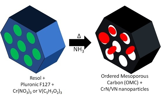
1. Introduction
2. Results and Discussion
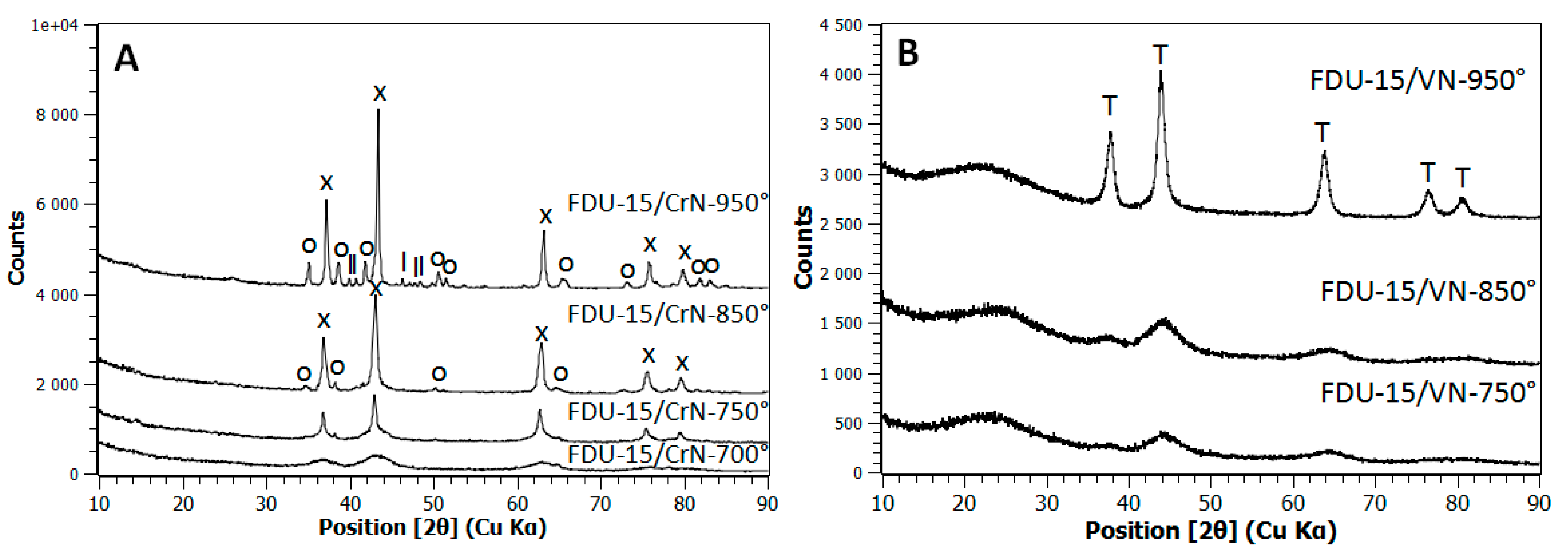
2.1. X-ray Diffraction (XRD) Characterization
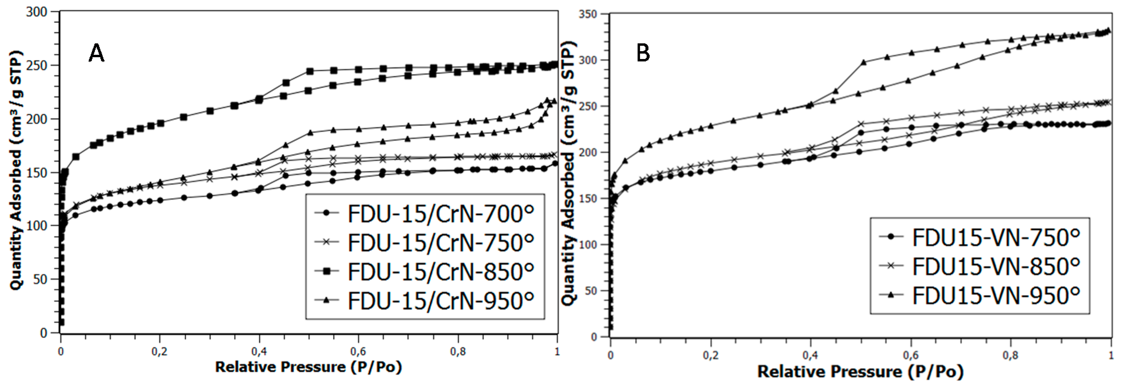
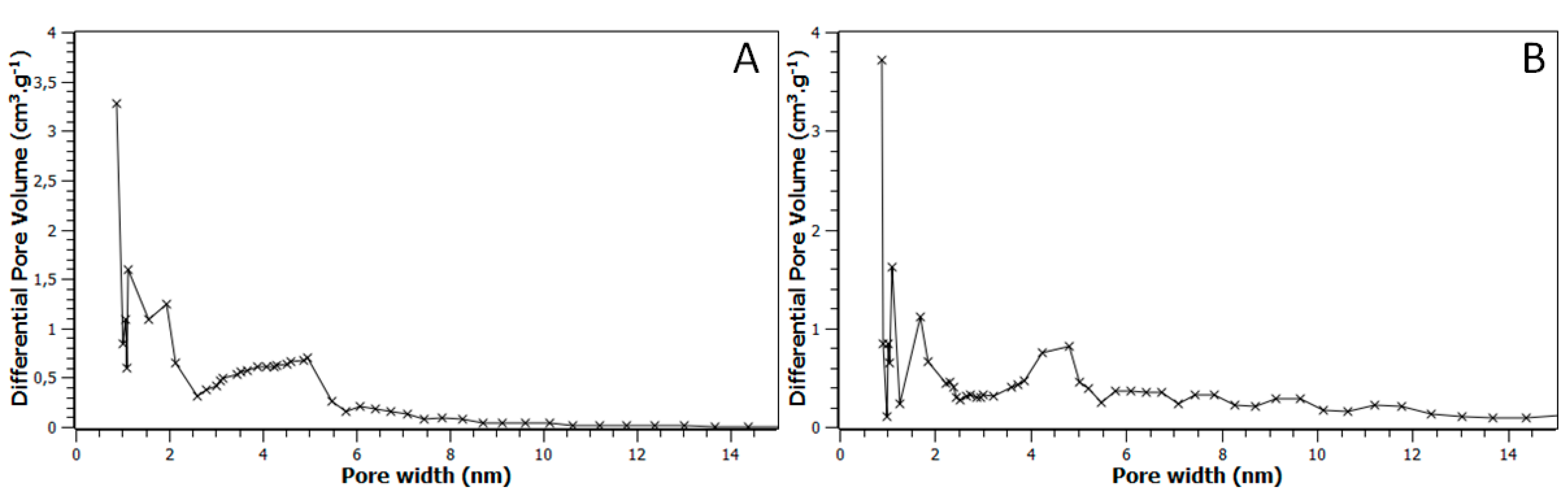
2.2. Nitrogen Adsorption Measurements (77K)
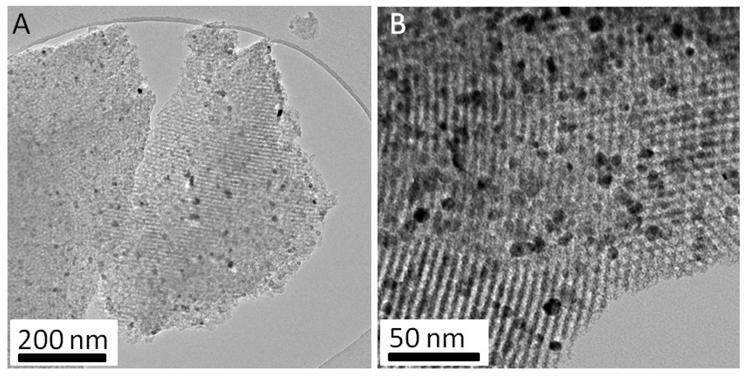
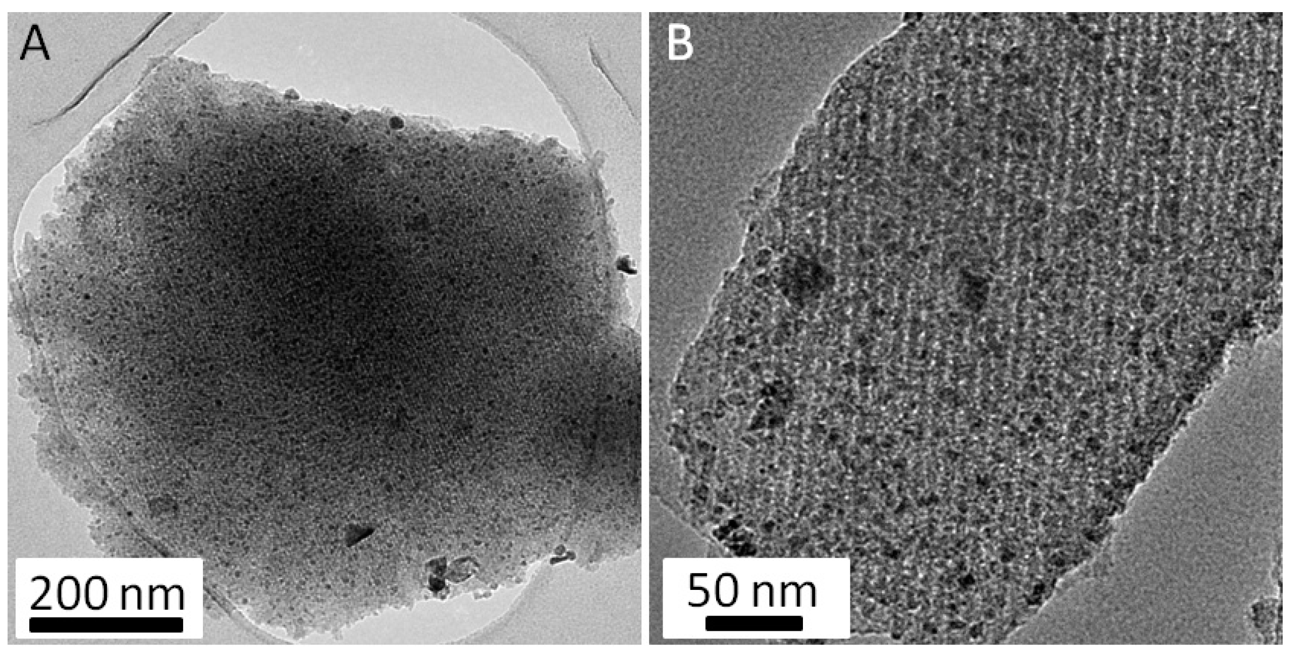
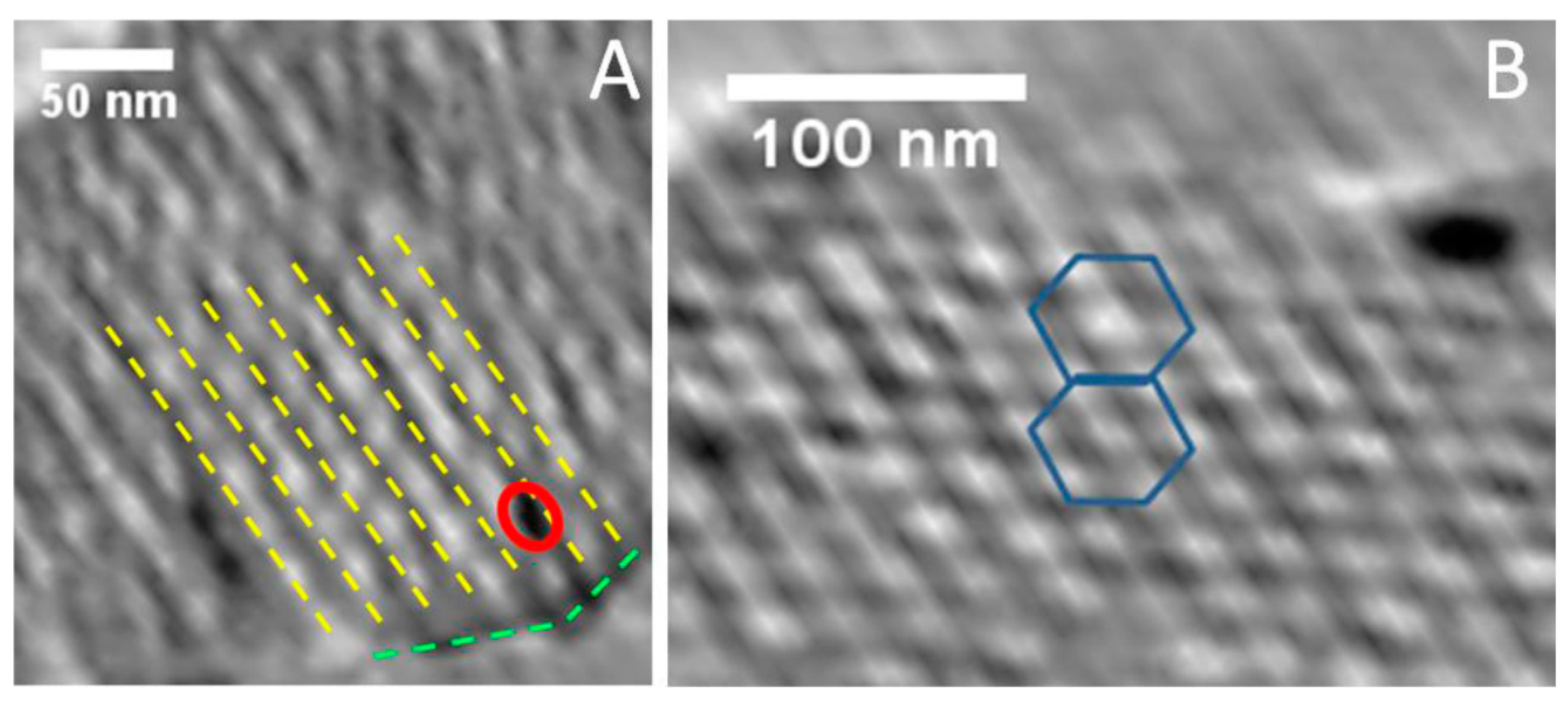
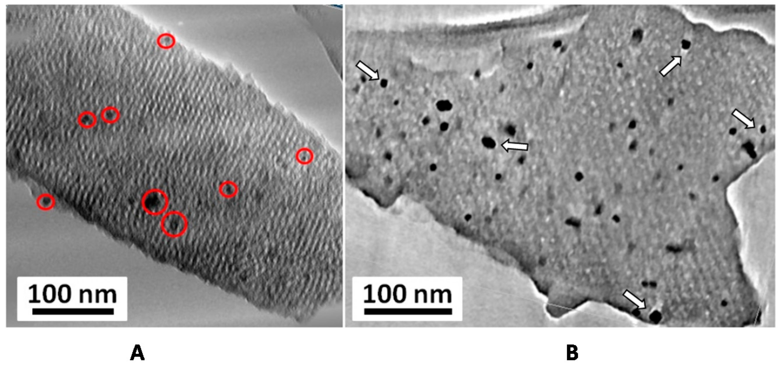
2.3. TEM Results
3. Experimental Section
4. Conclusions
Supplementary Materials
Author Contributions
Conflicts of Interest
References
- Cabana, J.; Monconduit, L.; Larcher, D.; Palacín, M.R. Beyond Intercalation-Based Li-Ion Batteries: The State of the Art and Challenges of Electrode Materials Reacting Through Conversion Reactions. Adv. Mater. 2010, 22, E170–E192. [Google Scholar] [CrossRef] [PubMed]
- Sun, Q.; Fu, Z.-W. An Anode Material of CrN for Lithium-Ion Batteries. Electrochem. Solid State Lett. 2007, 10, A189–A193. [Google Scholar] [CrossRef]
- Das, B.; Reddy, M.V.; Malar, P.; Osipowicz, T.; Subba Rao, G.V.; Chowdari, B.V.R. Nanoflake CoN as a high capacity anode for Li-ion batteries. Solid State Ion. 2009, 180, 1061–1068. [Google Scholar] [CrossRef]
- Wang, Y.; Liu, W.Y.; Fu, Z.-W. Electrochemistry of Mn4N with Lithium. Acta Phys. Chim. Sin. 2006, 22, 65–70. [Google Scholar]
- Wang, Y.; Fu, Z.-W.; Yue, X.-L.; Qin, Q.-Z. Electrochemical Reactivity Mechanism of Ni3N with Lithium. J. Electrochem. Soc. 2004, 151, E162–E167. [Google Scholar] [CrossRef]
- Fu, Z.-W.; Wang, Y.; Yue, X.-L.; Zhao, S.-L.; Qin, Q.-Z. Electrochemical Reactions of Lithium with Transition Metal Nitride Electrodes. J. Phys. Chem. B 2004, 108, 2236–2244. [Google Scholar] [CrossRef]
- Nagai, M. Transition-metal nitrides for hydrotreating catalyst—Synthesis, surface properties, and reactivities. Appl. Catal. A Genet. 2007, 322, 178–190. [Google Scholar] [CrossRef]
- Choi, D.; Blomgren, G.E.; Kumta, P.N. Fast and Reversible Surface Redox Reaction in Nanocrystalline Vanadium Nitride Supercapacitors. Adv. Mater. 2006, 18, 1178–1182. [Google Scholar] [CrossRef]
- Ghimbeu, C.M.; Raymundo-Piñero, E.; Fioux, P.; Béguin, F.; Vix-Guterl, C. Vanadium nitride/carbon nanotube nanocomposites as electrodes for supercapacitors. J. Mater. Chem. 2011, 21, 13268. [Google Scholar] [CrossRef]
- Lu, X.; Yu, M.; Zhai, T.; Wang, G.; Xie, S.; Liu, T.; Liang, C.; Tong, Y.; Li, Y. High Energy Density Asymmetric Quasi-Solid-State Supercapacitor Based on Porous Vanadium Nitride Nanowire Anode. Nano Lett. 2013, 13, 2628–2633. [Google Scholar] [CrossRef] [PubMed]
- Simon, P.; Gogotsi, Y. Materials for electrochemical capacitors. Nat. Mater. 2008, 7, 845–854. [Google Scholar] [CrossRef] [PubMed]
- Zhou, X.; Chen, H.; Shu, D.; He, C.; Nan, J. Study on the electrochemical behavior of vanadium nitride as a promising supercapacitor material. J. Phys. Chem. Solids 2009, 70, 495–500. [Google Scholar] [CrossRef]
- Huang, T.; Mao, S.; Zhou, G.; Wen, Z.; Huang, X.; Ci, S.; Chen, J. Hydrothermal synthesis of vanadium nitride and modulation of its catalytic performance for oxygen reduction reaction. Nanoscale 2014, 6, 9608. [Google Scholar] [CrossRef] [PubMed]
- Zhang, Q.; Uchaker, E.; Candelaria, S.L.; Cao, G. Nanomaterials for energy conversion and storage. Chem. Soc. Rev. 2013, 42, 3127. [Google Scholar] [CrossRef] [PubMed]
- Yin, Y.-X.; Xin, S.; Guo, Y.-G. Nanoparticles Engineering for Lithium-Ion Batteries. Part. Part. Syst. Charact. 2013, 30, 737–753. [Google Scholar] [CrossRef]
- Zhang, F.; Meng, Y.; Gu, D.; Yan; Yu, C.; Tu, B.; Zhao, D. A Facile Aqueous Route to Synthesize Highly Ordered Mesoporous Polymers and Carbon Frameworks with Ia3−d Bicontinuous Cubic Structure. J. Am. Chem. Soc. 2005, 127, 13508–13509. [Google Scholar] [CrossRef] [PubMed]
- Meng, Y.; Gu, D.; Zhang, F.; Shi, Y.; Yang, H.; Li, Z.; Yu, C.; Tu, B.; Zhao, D. Ordered Mesoporous Polymers and Homologous Carbon Frameworks: Amphiphilic Surfactant Templating and Direct Transformation. Angew. Chem. 2005, 117, 7215–7221. [Google Scholar] [CrossRef]
- Ramasamy, E.; Jo, C.; Anthonysamy, A.; Jeong, I.; Kim, J.K.; Lee, J. Soft-Template Simple Synthesis of Ordered Mesoporous Titanium Nitride-Carbon Nanocomposite for High Performance Dye-Sensitized Solar Cell Counter Electrodes. Chem. Mater. 2012, 24, 1575–1582. [Google Scholar] [CrossRef]
- Schlienger, S.; Ersen, O.; Roiban, L.; Parmentier, J. Direct Synthesis of TiN/Mesoporous Carbon Nanocomposite by Nitridation of a Hybrid Inorganic/Organic Mesostructured Material. J. Am. Ceram. Soc. 2011, 94, 4142–4145. [Google Scholar] [CrossRef]
- Buchwald, V.F.; Scott, E.R.D. First Nitride (CrN) in Iron Meteorites. Nat. Phys. Sci. 1971, 233, 113–114. [Google Scholar] [CrossRef]
- Huang, C.-H.; Gu, D.; Zhao, D.; Doong, R.-A. Direct Synthesis of Controllable Microstructures of Thermally Stable and Ordered Mesoporous Crystalline Titanium Oxides and Carbide/Carbon Composites. Chem. Mater. 2010, 22, 1760–1767. [Google Scholar] [CrossRef]
- Mangun, C.L.; Benak, K.R.; Economy, J.; Foster, K.L. Surface chemistry, pore sizes and adsorption properties of activated carbon fibers and precursors treated with ammonia. Carbon 2001, 39, 1809–1820. [Google Scholar] [CrossRef]
- Maldonado-Hódar, F. Surface morphology, metal dispersion, and pore texture of transition metal-doped monolithic carbon aerogels and steam-activated derivatives. Microporous Mesoporous Mater. 2004, 69, 119–125. [Google Scholar] [CrossRef]
- Maldonado-Hódar, F.J.; Moreno-Castilla, C.; Rivera-Utrilla, J.; Hanzawa, Y.; Yamada, Y. Catalytic Graphitization of Carbon Aerogels by Transition Metals. Langmuir 2000, 16, 4367–4373. [Google Scholar] [CrossRef]
- Matei Ghimbeu, C.; Puscasu, A.; Martinez de Yuso, A.; Zlotea, C.; Oumellal, Y.; Latroche, M.; Vix-Guterl, C. One-pot synthesis of tailored Pd–Co nanoalloy particles confined in mesoporous carbon. Microporous Mesoporous Mater. 2016, 223, 79–88. [Google Scholar] [CrossRef]


| Samples | SDFT (m2·g−1) * | Vtotal pores (cm3·g−1) * | Vmicropores (cm3·g−1) * | Vmesopores (cm3·g−1) * |
|---|---|---|---|---|
| FDU-15-850°-Ar | 344 | 0.29 | 0.11 | 0.18 |
| FDU-15-850°-NH3 | 524 | 0.36 | 0.18 | 0.18 |
| FDU-15/CrN-700° | 660 | 0.22 | 0.15 | 0.07 |
| FDU-15/CrN-750° | 357 | 0.16 | 0.09 | 0.07 |
| FDU-15/CrN-850° | 777 (983) | 0.33 (0.42) | 0.16 (0.20) | 0.17 (0.22) |
| FDU-15/CrN-950° | 709 | 0.28 | 0.14 | 0.14 |
| FDU-15/VN-750° | 1046 | 0.35 | 0.23 | 0.12 |
| FDU-15/VN-850° | 870 (1101) | 0.35 (0.44) | 0.18 (0.23) | 0.17 (0.21) |
| FDU-15/VN-950° | 1154 | 0.49 | 0.22 | 0.27 |
© 2016 by the authors; licensee MDPI, Basel, Switzerland. This article is an open access article distributed under the terms and conditions of the Creative Commons Attribution (CC-BY) license (http://creativecommons.org/licenses/by/4.0/).
Share and Cite
Kiener, J.; Ersen, O.; Parmentier, J. Mesoporous C/CrN and C/VN Nanocomposites Obtained by One-Pot Soft-Templating Process. Inorganics 2016, 4, 22. https://doi.org/10.3390/inorganics4030022
Kiener J, Ersen O, Parmentier J. Mesoporous C/CrN and C/VN Nanocomposites Obtained by One-Pot Soft-Templating Process. Inorganics. 2016; 4(3):22. https://doi.org/10.3390/inorganics4030022
Chicago/Turabian StyleKiener, Julien, Ovidiu Ersen, and Julien Parmentier. 2016. "Mesoporous C/CrN and C/VN Nanocomposites Obtained by One-Pot Soft-Templating Process" Inorganics 4, no. 3: 22. https://doi.org/10.3390/inorganics4030022
APA StyleKiener, J., Ersen, O., & Parmentier, J. (2016). Mesoporous C/CrN and C/VN Nanocomposites Obtained by One-Pot Soft-Templating Process. Inorganics, 4(3), 22. https://doi.org/10.3390/inorganics4030022