Article

Mononuclear Dysprosium(III) Complexes with Triphenylphosphine Oxide Ligands: Controlling the Coordination Environment and Magnetic Anisotropy

1
School of Science and the Environment, Division of Chemistry, Manchester Metropolitan University, Manchester M15 6BH, UK
2
Department of Chemistry, IIT Bombay, Mumbai 400076, India
3
School of Science and Technology, Nottingham Trent University, Nottingham NG11 8NS, UK
4
School of Sciences, University of Wolverhampton, Wolverhampton WV1 1LY, UK
5
School of Chemistry, Monash University, Clayton, VIC 3800, Australia
*
Authors to whom correspondence should be addressed.
Inorganics 2018, 6(2), 61; https://doi.org/10.3390/inorganics6020061
Submission received: 1 May 2018 / Revised: 8 June 2018 / Accepted: 9 June 2018 / Published: 12 June 2018
(This article belongs to the Special Issue Magnetic Lanthanide Complexes)

Abstract

:
We report the synthesis, structural and magnetic characterization of five mononuclear DyIII ion complexes using triphenylphosphine oxide as a monodentate ligand. They have formulae [DyIII(OPPh3)3(NO3)3] (1), [DyIII(OPPh3)4(NO3)2](NO3) (2), [DyIII(OPPh3)3Cl3] (3), [DyIII(OPPh3)4Cl2]Cl (4) and [DyIII(OPPh3)4Cl2](FeCl4) (5). These complexes are characterized using single crystal X-ray diffraction, which revealed that each complex has a unique coordination environment around the DyIII ion, which results in varying dynamic magnetic behavior. Ab initio calculations are performed to rationalize the observed magnetic behavior and to understand the effect that the ligand and coordination geometry around the DyIII ion has on the single-molecule magnet (SMM) behavior. In recent years, seven coordinate DyIII complexes possessing pseudo ~D5h symmetry are found to yield attractive blocking temperatures for the development of new SMM complexes. However, here we show that the strength of the donor ligand plays a critical role in determining the effective energy barrier and is not simply dependent on the geometry and the symmetry around the DyIII ion. Seven coordinate molecules possessing pseudo D5h symmetry with strong equatorial ligation and weak axial ligation are found to be inferior, exhibiting no SMM characteristics under zero-field conditions. Thus, this comprehensive study offers insight on improving the blocking temperature of mononuclear SMMs.

Graphical Abstract

1. Introduction

The magnetic properties of mononuclear lanthanide ion coordination complexes have come to the forefront of research in the field of molecular magnetism due to the observation of slow relaxation of magnetization [1,2]. Complexes that exhibit this behavior have been termed single-molecule magnets (SMMs) or single-ion magnets (SIMs), terms that are used interchangeably [3,4]. Molecule-based magnets offer the advantage of tunable properties; most notably the magnetic properties of a single lanthanide ion are dependent on how the electronic structure is influenced by the ligand coordination environment around the ion [4]. The key to a successful SMM is the presence of a strong magnetic anisotropy and the strength and symmetry of the ligand field [3,4]. The most utilized ion for the design and synthesis of new SMMs is DyIII [5,6]. Chilton, Long, Ruiz and their co-workers have used simple electrostatic models to predict the ideal coordination geometry/environment for DyIII that would result in a SMM with a considerable magnetic anisotropy [7,8,9]. This “ideal” coordination environment involves negatively charged ligands coordinating along a single axis due to the prolate nature of the f electron density around the DyIII ion. This design approach has provided spectacular recent results for a dysprosium metallocene complex with cyclopentadienyl ligands situated above and below the DyIII ion. The remarkable magnetic anisotropy (Ueff = 1223 cm−1) resulted in a hysteresis blocking temperature of 60 K, the highest thus far achieved for a single-molecule magnet [10,11]. These studies clearly reveal that controlling the coordination geometry around the metal ion is extremely important in achieving high-performing molecular magnets in the future.
A series of SMMs with five-fold symmetry of type [Dy(OR)2(L)5] have also produced large Ueff values, including a [Dy(H2O5)5(OPtBu(NHiPr)2](I3) complex reported by Gupta and co-workers that utilized phosphine oxide ligands that lie in the axial position, with the five water molecules lying in the equatorial plane (pseudo D5h symmetry) [12]. A small number of other phosphine oxide based lanthanide complexes with large anisotropy barriers have also been reported [13,14,15]. We believe bulky phosphine oxide ligands offer the possibility to control the coordination number, depending on the reaction conditions, and used in conjunction with the DyIII ion, thus offering a way to design new SMMs. Levason and co-workers show it is possible to vary and control the coordination environment around a LnIII ion using, for example, triphenylphosphine oxide (TPPO or OPPh3) ligands [16,17]; however, complexes that contain the DyIII ion have strangely been neglected. Here, we have isolated several DyIII analogues and explored how modification of the coordination environment affects the magnetic properties. We report the isolation of five DyIII complexes of molecular formula [DyIII(OPPh3)3(NO3)3] (1), [DyIII(OPPh3)4(NO3)2](NO3) (2), [DyIII(OPPh3)3Cl3] (3), [DyIII(OPPh3)4Cl2]Cl (4) and [DyIII(OPPh3)4Cl2](FeCl4) (5). Compounds 15 display coordination numbers ranging from six to nine, each with different coordination geometries and differing dynamic magnetic behavior. Furthermore, we have undertaken an ab initio CASSCF calculation to probe the origin of magnetic anisotropy in these systems, offer insight into the observed magnetic behavior and suggest ways to increase the magnetic anisotropy via ligand modification.

2. Results and Discussions

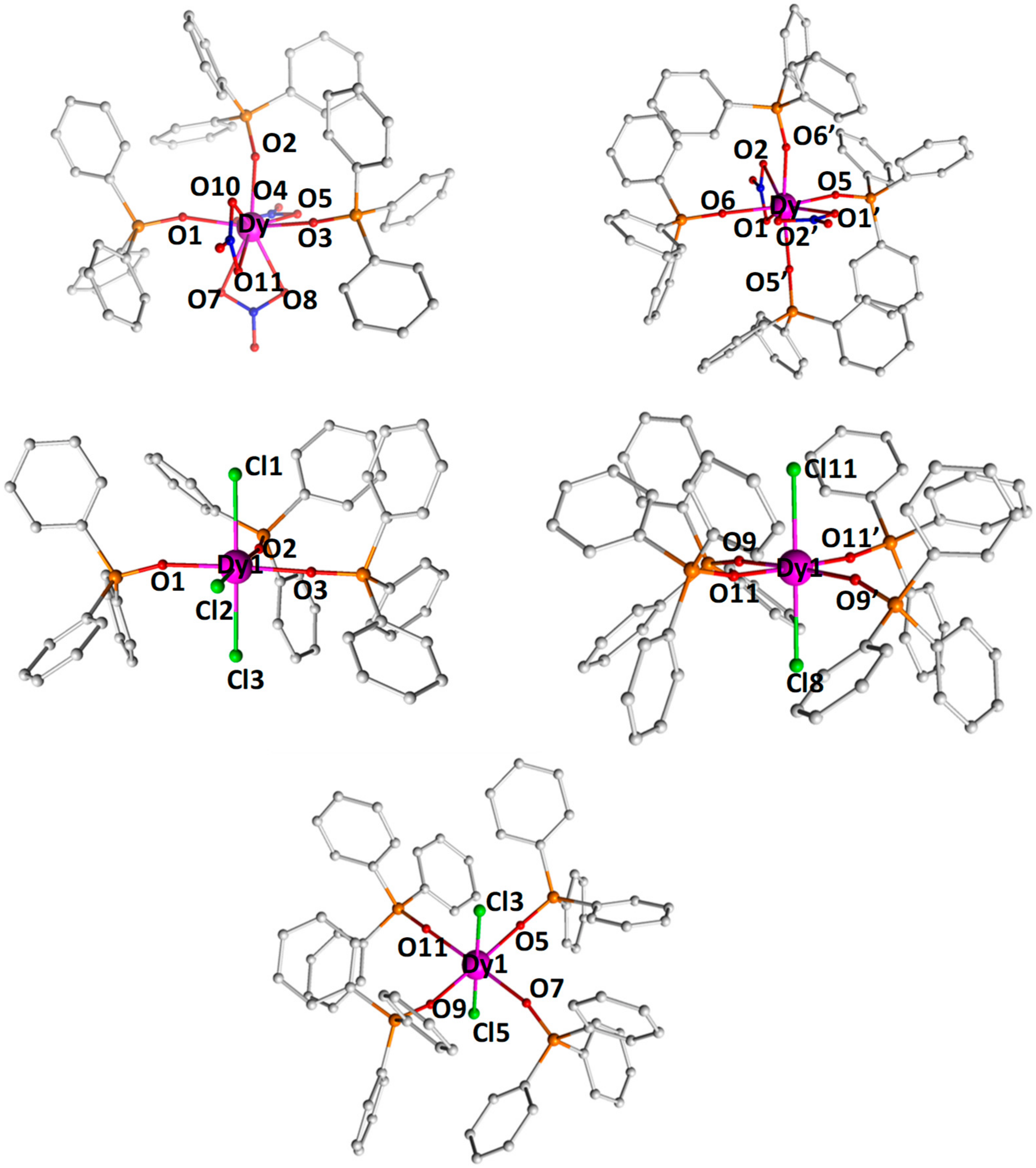
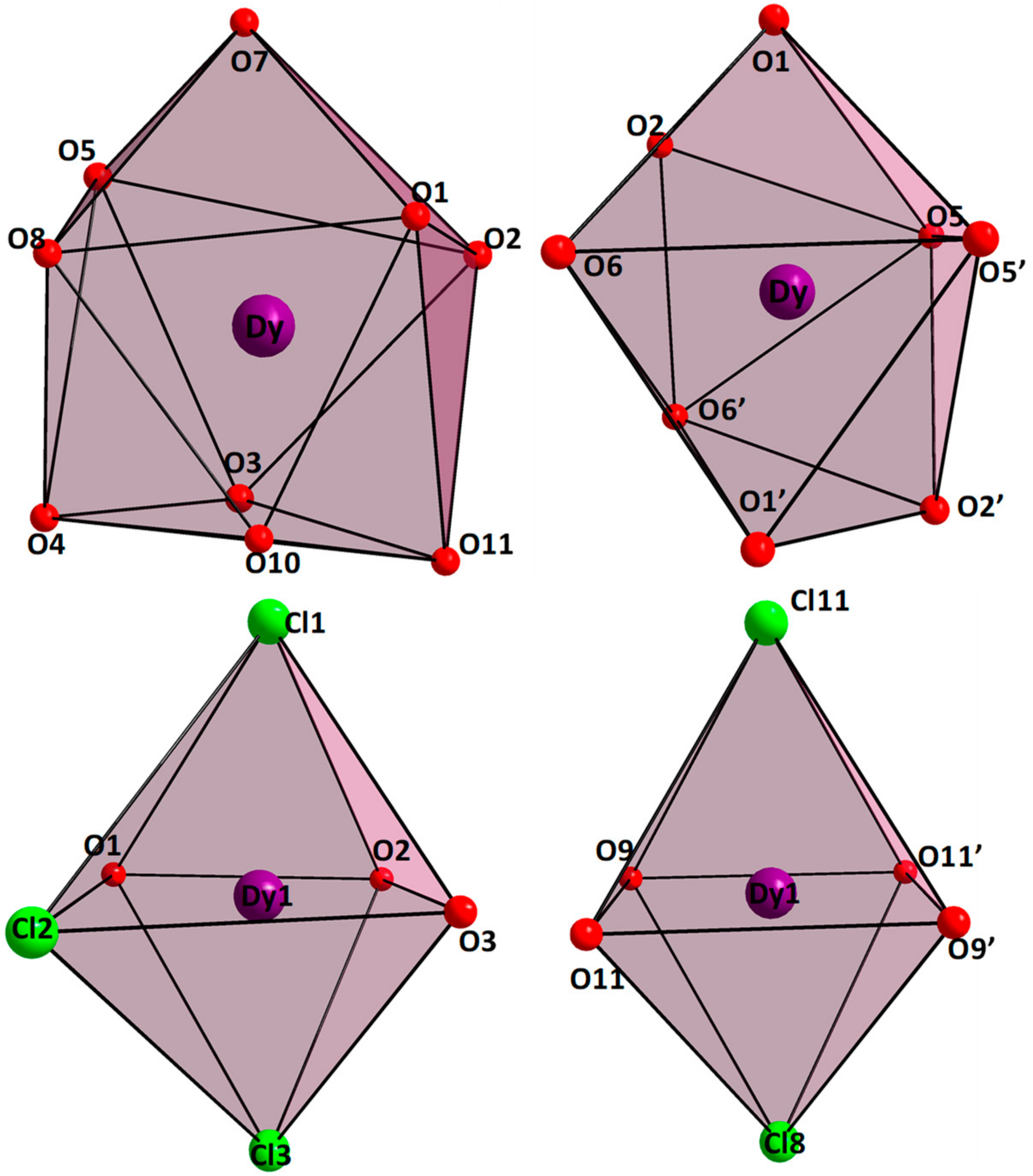
2.1. Synthesis and Molecular Structure

Complex 1, [DyIII(OPPh3)3(NO3)3]·2(CH3)2CO, was synthesised using TPPO in acetone. By modification of the dysprosium salt; NO3 vs. Cl and reaction solvent; acetone vs. ethanol, it is possible to isolate several different coordination complexes, each with a unique coordination environment using the TPPO ligand (Figure 1). FeCl3 was used in the synthesis of 5 in order to isolate a further unique coordination environment, this being the previously reported [DyIII(OPPh3)5Cl](FeCl4)2 complex reported by Wang and co-workers [18], however, the product of 5 differed from that reported, resulting in a first coordination sphere identical to that of 4, with four TPPO ligands and two chloride ions—[DyIII(OPPh3)4Cl2](FeCl4) (5).
Single crystal X-ray analysis revealed that 15 are mononuclear complexes (Figure 1). Complexes 1, 3 and 4 crystallize in the monoclinic space groups, P21/n, P21/c and C2/c, respectively. Complex 2 crystallizes in the orthorhombic space group Pccn, while complex 5 crystallizes in the triclinic space group, P-1. The coordination geometry around DyIII ion in 15 was examined by SHAPE [19] software (Tables S1 and S2). Complex 1 contains three TPPO and three nitrate ligands. The TPPO ligands coordinate via the O-atom, while the three nitrate anions chelate via two of the O-atoms. The O-atoms of the three TPPO ligands and the two O-atoms of one nitrate anion lie in a plane with a distorted pentagonal arrangement, with the two remaining nitrate anions chelating above and below the pentagon. The ion is therefore nine coordinate, with a spherical capped square antiprism geometry (CShM: 1.9). Complex 2 contains four TPPO ligands, with the O-atoms lying in a plane forming a distorted square. The two chelating nitrate anions lie above and below the plane. The DyIII ion is therefore eight coordinate, with a triangular dodecahedron geometry (CShM: 2.5). A non-coordinating nitrate counterion is also present. Complex 3 contains three TPPO and three chloride ions. The DyIII ion is six coordinate, with a distorted octahedral geometry (CShM: ~0.6). The three TPPO and chloride ligands each occupy a plane passing through the metal ion, thus giving rise to a meridional arrangement. Complexes 4 and 5 have the same coordination environment (CShM: ~0.6), the only difference being 4 has a non-coordinating Cl counterion, whereas 5 has a non-coordinating (FeCl4) counterion. Again, the complexes are six coordinate, with distorted octahedral geometries. In these complexes, the TPPO ligands lie in the equatorial plane, with the two chloride ions being axial. The average Dy–O bond lengths for compounds 15 are 2.41, 2.33, 2.25, 2.24, and 2.24 Å, respectively. Figure 2 shows a polyhedral representation of the coordination environment around the DyIII ion. The structural results reveal that the coordination environment is different for 14. We discuss in the next section the experimental magnetic results (static and dynamic) and how the modifications in coordination environment affect the electronic structure and therefore the magnetic anisotropy. Selected bond lengths are given in Table S3. The closest intermolecular Dy···Dy contact is found to be 11.04, 11.72, 10.10, 10.60 and 10.45 Å for 15, respectively. The closest intermolecular Dy···Fe distance for 5 is 9.929 Å.

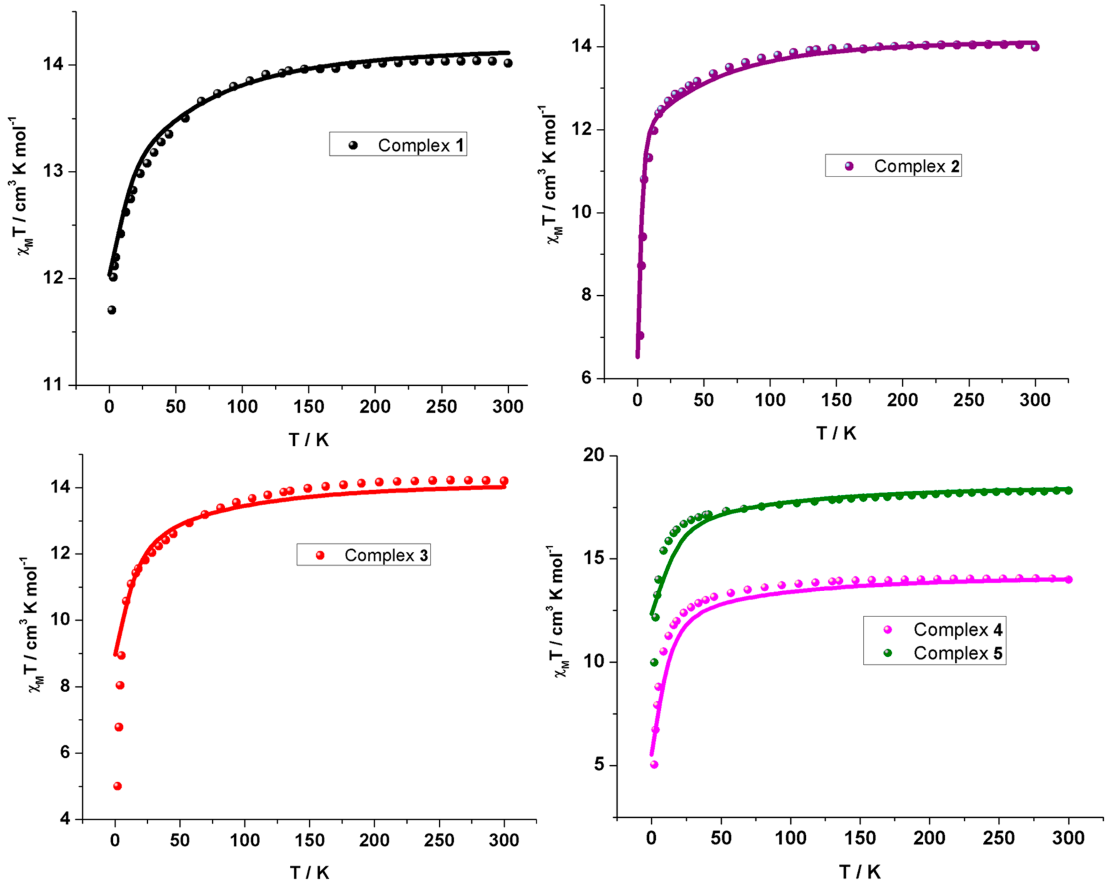
2.2. Magnetic Properties

DC magnetic studies have been conducted on compounds 15 in a 1 T field in the temperature range of 2–300 K (Figure 3). The χMT products decrease gradually for 15 as the temperature is reduced from 300 K to 12.11, 5.56, 5.00, 5.03 and 9.98 cm3·mol−1·K at 2 K in a field of 1 T. The room temperature values of 14.02, 14.10, 14.20, 13.99 and 18.30 cm3·mol−1·K are consistent with the expected values for an isolated DyIII (4f9, 6H15/2) ion of 14.17 cm3·mol−1·K (14), with the value for 5 consistent with the presence of a DyIII ion and a non-coordinated {FeIIICl4} counterion (3d5, g = 2, χMT = 4.375 cm3·mol−1·K). The χMT products are found to decrease upon reducing the temperature for 15, which is attributed to depopulation of the mJ levels arising from the crystal field levels. The molar magnetization at 2 K for 15 do not saturate at 5 T, but rather show an almost linear dependence above 2 T, Figure S1. The magnitude of the magnetization values is much lower than expected for a free DyIII ion andis characteristic of strong crystal field effects. The magnetization value of 5 is much larger than those of 14 due to the paramagnetic FeIII counter ion.

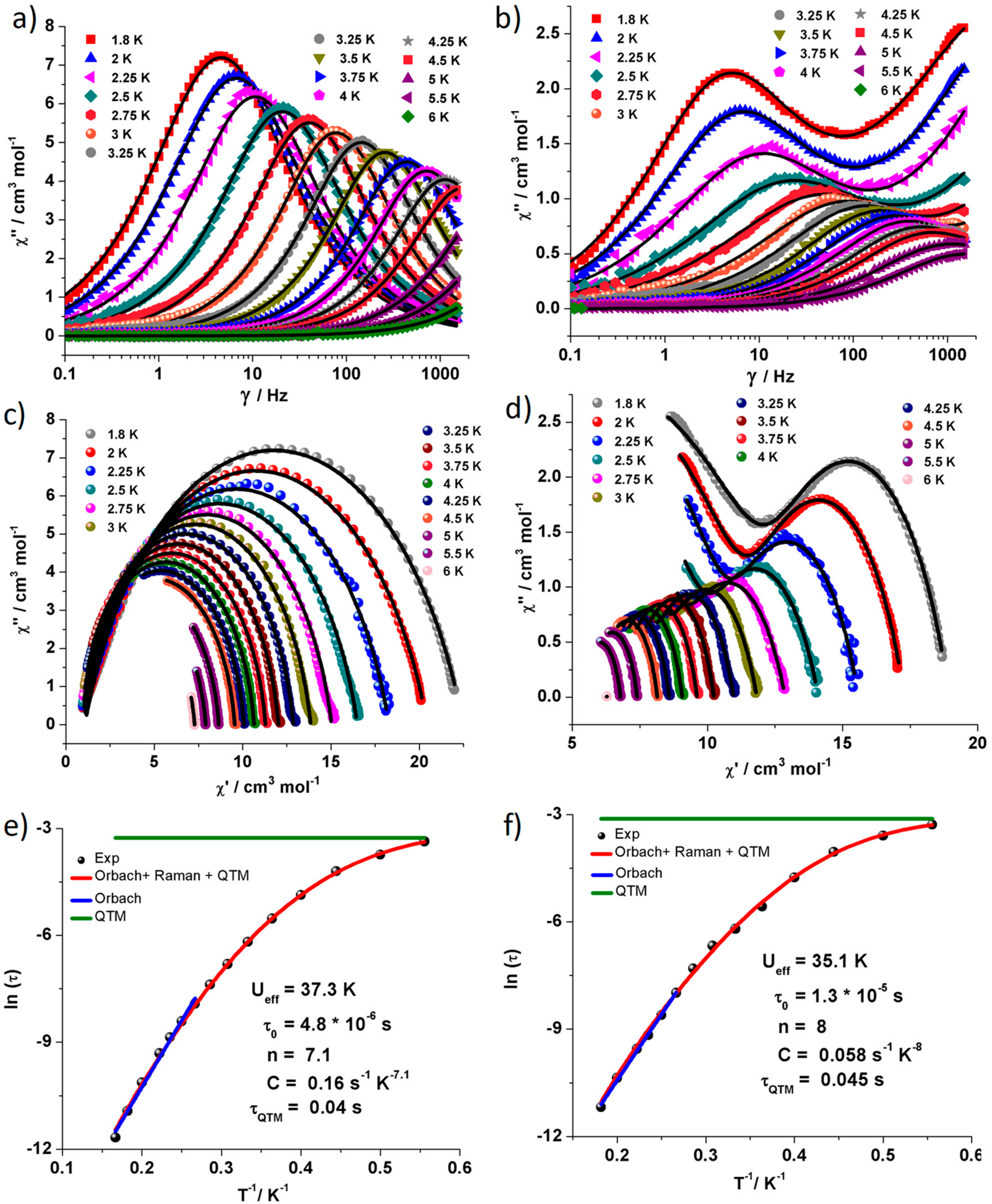
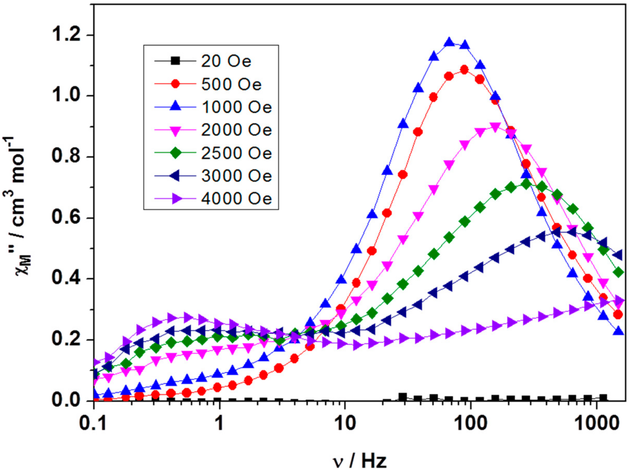
2.3. Dynamic Magnetic Properties

To investigate the possibility of slow magnetic relaxation, ac magnetic studies have been conducted on compounds 15. It is found that the χM” vs. T plots (fixed frequency) reveal no out-of-phase susceptibility signals in the absence of an applied static dc field, except for a very weak frequency dependence for 3 (Figure S2). It was found, however, upon application of a static, dc field (Hdc = 2000 Oe); possible SMM behavior is observed for all the complexes. For 2, 4 and 5 we observe peak tails, with no maximum (Figure S3), whereas frequency dependent maxima are found for 1 and 3 (Figure S4). Fitting the data for 1 and 3 to the Arrhenius law [τ = τo∙exp(Ueff/kBT)] reveals an effective anisotropy barrier to magnetization reversal of Ueff = 21.7 ± 0.1 K with τo = 1.66 ± 0.01 × 10⁻⁷ s (R = 0.99) for 1 and Ueff = 20.9 ± 0.1 K with τo = 1.04 ± 0.01 × 10⁻⁶ s (R = 0.99) for 3 (Figure S4). To get further accuracy in these parameters, we then determined the optimum dc field accurately as described in the Experimental section, using variable field, fixed temperature, χM” vs. frequency plots, and it was found to be 1000 Oe for 1 and 3.
Thus, frequency dependent out-of-phase susceptibility and Cole–Cole measurements for 1 and 3 were performed with 1000 Oe at frequencies ranging from 0.1–1500 Hz and at temperatures between 2 and 6 K (Figure 4). The Cole–Cole plots of χM’ versus χM” data showing semicircular profiles confirms a single relaxation process for 1 and two relaxations process for 3 (Figure 4c,d). The second process in 3 is found to be temperature independent and this could be attributed to the relaxation via QTM. Fitting the temperature dependent relaxation data using CC-FIT program [20] allowed for the extraction of the relaxation times with the various relaxation processes (Figure 4e,f) using the following equation [1/τ = 1/τQTM + CTn + τo−1∙exp(Ueff/kBT)], where 1/τQTM corresponds to the relaxation process via quantum tunneling pathway, the CTn term corresponds to the relaxation via Raman process, and the last term accounts for the Orbach relaxation pathway [21,22]. The values obtained from the best fit are n = 7.1 ± 0.2, C = 0.157 ± 0.004 s−1 K−7.1, Ueff = 37.3 ± 1.5 K and τo = 4.8 ± 0.02 × 10⁻⁶ s (R = 0.999) for 1 and n = 8.0 ± 0.2, C = 0.058 ± 0.007 s−1 K−8, Ueff = 35.1 ± 2.3 K and τo = 1.31 ± 0.04 × 10⁻⁵ s (R = 0.999) for 3. A QTM relaxation time, τQTM, of 0.04 s and 0.045 s are estimated for 1 and 3, respectively. At a field of 1000 Oe the relaxation is slower; thus, a larger effective barrier is obtained compared to the barrier at 2000 Oe and a reasonable pre-exponential factor (10−6 and 10−5 s) allows confidence in the extracted values for an SMM [3].
The Ueff parameters revealed here are significantly smaller than the above-mentioned complex containing axially ligated phosphine oxide ligands (Ueff ~650 cm−1) [12], coupled with the fact that slow magnetic relaxation is only observable in an applied magnetic field (fast quantum tunneling of the magnetization (QTM)), indicating the importance of the number and position of the phosphine oxide ligand(s) and possibly the choice of the “co-ligand” (see later).

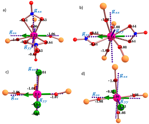
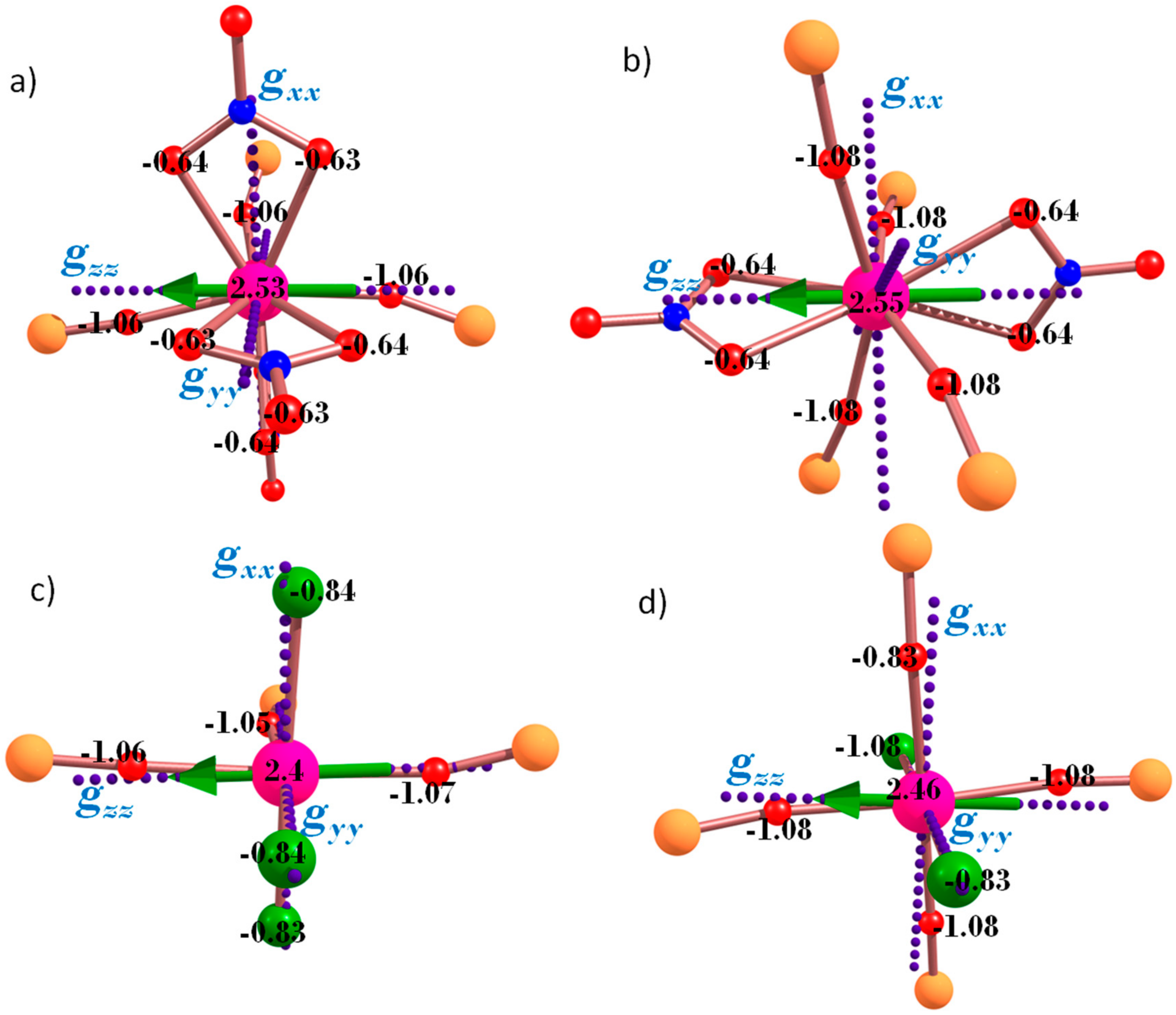
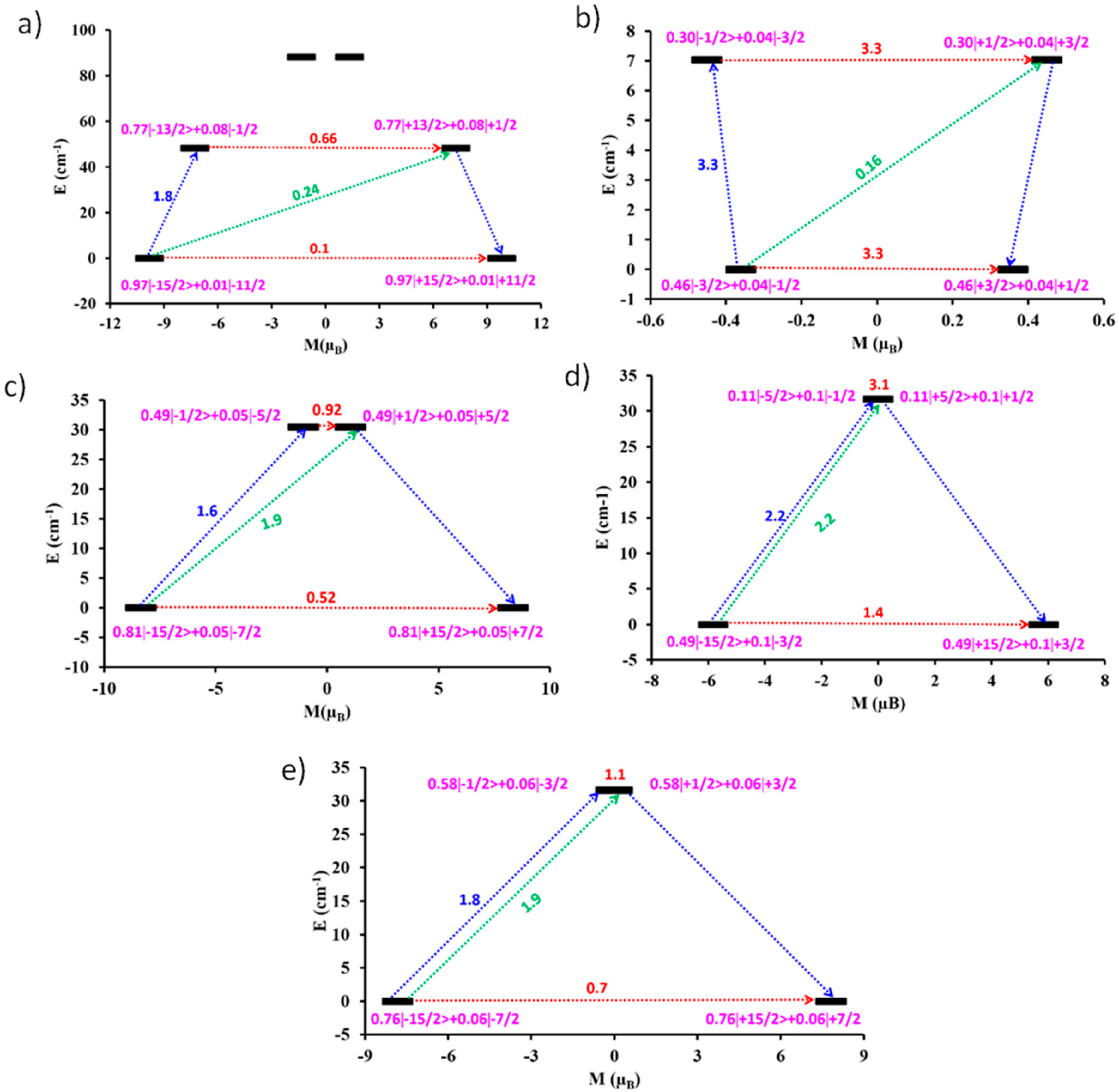
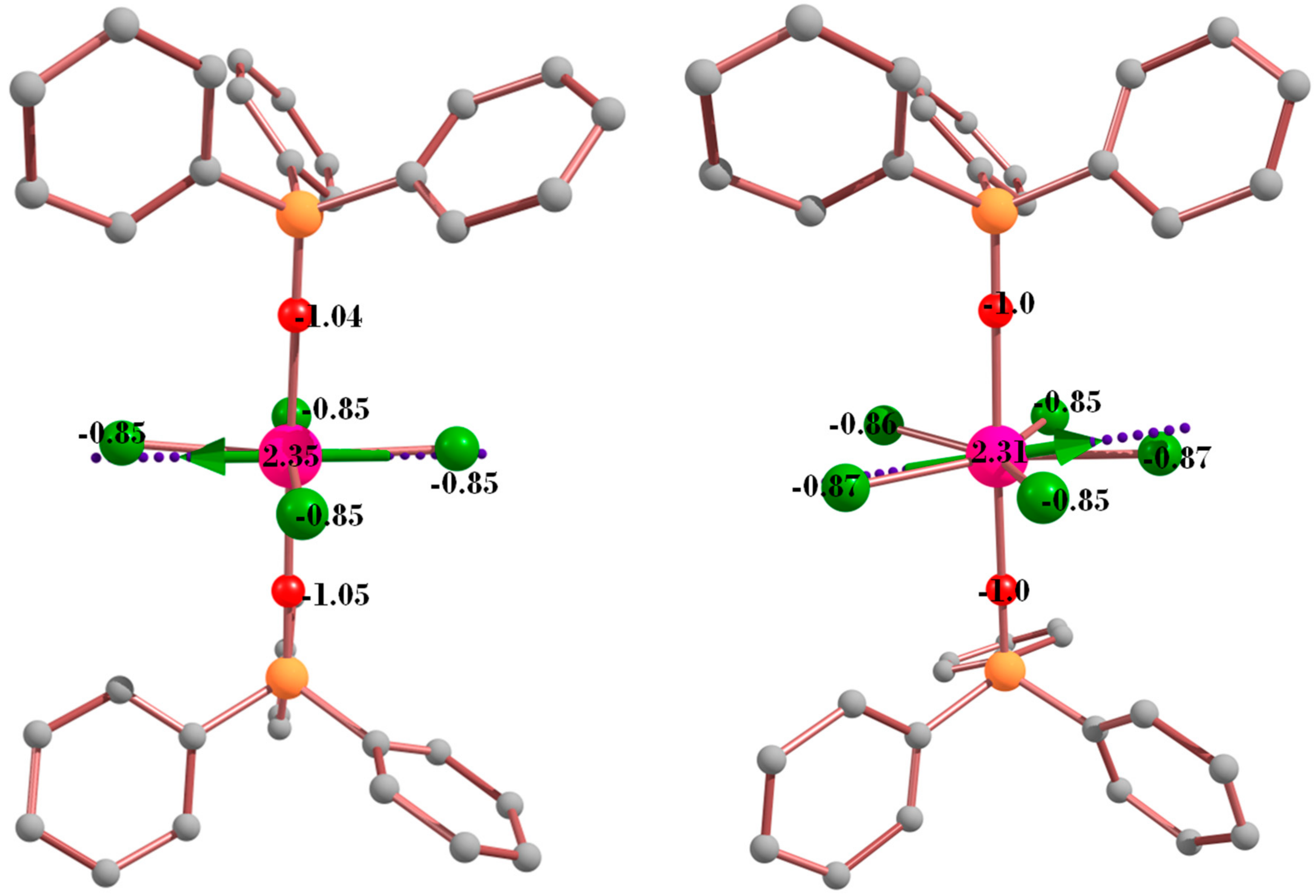
3. Theoretical Studies

We have performed detailed CASSCF/RASSI/SINGLE_ANISO ab initio calculations to probe the electronic structure and magnetic anisotropy of the DyIII ions in 15 to account for the observed static and dynamic magnetic behavior. The results reveal the ground state Kramers doublet (KD) of complexes 15 has strong transverse components (gx, gy), suggesting strong mixing of the wavefunction and thus not the ideal Ising type anisotropy desired for slow relaxation of the magnetization. This is, however, less so for complex 1 (see Table 1 and Table S4). This large transverse component in the ground KD indicates their inability to block the magnetization and therefore predicts an absence of SIM behavior at zero field. This supports the experimental observations in all complexes; however, all the eight KDs are found to extend over an energy gap of 333.1, 312.1, 368.0, 394.8 and 396.7 cm−1 for complexes 15, respectively (see Table 1 and Table S5). The ab initio computed magnetic susceptibility data (Figure 3—solid lines) are in good agreement with the experimental magnetic data, which discloses the consistency of the parameters extracted.
In 1, the ground state gzz axis is found to be aligned towards the O-atoms of two TPPO ligands (see Figure 5a) and this is preferably due to the shortest Dy–O (~2.29 Å) bond distances of the TPPO ligand compared to the Dy–O (~2.45 Å) distances of the (NO3) ligand. This can be ascribed to the oblate 4f electron density of DyIII, which prefers to locate perpendicular to the shortest Dy–O bond to avoid a strong electrostatic repulsion with the closest ligated atom. This results in the perpendicular orientation of the ground state gzz tensor with respect to the 4f electron density. This assumption has been further corroborated by ab initio computed Loprop charges (see computational sections), which reveals larger negative charges on the O-atoms (−1.06) of TPPO ligands, compared to the other O-atoms. This relatively large charge on the O-atom of the TPPO ligand is due to the fact that the donation of a lone pair from the oxygen to an empty DyIII orbital forms a coordinate bond. This in turn weakens the P=O bond, leading to a large charge polarization, with a residual positive charge on P and concomitant negative charge on the oxygen atom, reflecting a P+–O scenario. This is similar to other reported complexes possessing the P=O coordinating moiety [12]. The presence of three TPPO ligands and a nitrate in the equatorial plane (~90° to each other) enforces the rather strong equatorial ligation (shortest bond lengths, with the largest negative charges on the donor ligand atoms), which competes with the axial interactions of the two chelating nitrate groups (bond lengths of which are slightly longer), leading to a very small ground to first excited state gap and a significant transverse anisotropy. Desirably, for the DyIII ion, very strong axial ligands combined with no or extremely weak equatorial ligands lead to a very large ground-first excited state gap, but this condition is absent in all complexes (also see below). Thus, for 15, the calculations predict the absence of zero field SMM behavior due to the small ground-first excited state energy gap, combined with the large transverse component to the anisotropy.
Calculations for 1 yield a ground to first excited state KD energy gap of 48.3 cm−1 (Table 1). The experimental data reveals an absence of slow magnetic relaxation at zero field, which corroborates the above analysis; however, field-induced SIM behavior is observed, with a Ueff of 37.3 K (25.9 cm−1). This value is smaller compared to the theoretical estimate. This may be associated with multiple factors such as (i) the ground state tunneling in 1 is still significant and this has not been factored in the estimated Ucal value; (ii) as has been shown by some of us earlier, intermolecular interactions [23] and other effects play an important role in diminishing the Ueff value; (iii) other possible relaxation pathways such as spin-phonon relaxation, which have not been taken into consideration.
For complex 2, the addition of a fourth TPPO ligand, in place of a nitrate, leads to four strong equatorial donations to the DyIII ion, with weaker axial donations by the two chelating nitrate ions. This leads to the stabilization of a rather hard-plane anisotropy. This ligand field is better suited for the prolate ErIII ion, as for the DyIII ion, this configuration dramatically reduces the ground-first excited state gap (7 cm−1, see Table 1) compared to 1. As expected for the hard-plane anisotropy, the gxx, gyy axes are found to point along the {Dy(O-P)4} plane, while the gzz axial direction lies along the two (NO3) ligands (Figure 5b).
The geometry for 3 is like that for 1, except that the three nitrate ions have been replaced by three chloride ions. In 3, the ground state gzz axis is again found to be aligned towards the O-atoms of two TPPO ligands (see Figure 5c) and this is preferably due to the shortest Dy–O (~2.29 Å) bond distances of the TPPO ligand compared to the Dy–Cl (~2.61 Å) distances of the Cl ligand. The chloride ions are comparatively weaker ligands, with longer Dy–Cl bond lengths (2.61 Å), compared to the nitrate ions (2.45 Å). Thus, the equatorial position is comparatively better (3xTPPO and one Cl ligand); however, the relatively strong axial repulsion exhibited by the nitrate ions in 1, is also replaced by the “weaker” Cl ion. Therefore, this leads to a smaller ground-first excited state gap (30.5 cm−1) compared to complex 1.
Similarly, for 4 and 5, which contain four equatorial TPPO and two axial chloride ligands, the ground gzz is computed to be directed towards the O-atoms of two TPPO ligands (Figure 5d). The Dy–O and Dy–Cl bond distances are found to be 2.24 Å and 2.62 Å, respectively, and the Loprop charge investigations reveal large negative charges on the TPPO O-atoms (−1.08) and smaller negative charges on Cl ions (−0.83) (Figure 5d). Thus, we observe a ground-first excited state energy gap of 31.7 and 31.6 cm−1 for 4 and 5, respectively (Table 1).
To ascertain confidence in our computed energy barriers, we have constructed relaxation mechanisms for magnetization blockade for each complex (Figure 6). In all cases, the ground state axiality is removed, leading to significant transversal matrix elements, resulting in large quantum tunneling of magnetization (QTM) processes (0.1, 3.3, 0.52, 1.4 and 0.7 μB for complexes 15 respectively). The prominent transverse components in the ground KD destroys the SIM characteristics (i.e., promotes QTM). QTM can, however, be suppressed in the ground KD by the application of a static dc magnetic field to promote relaxation via excited states. Notably, however, the enhanced transverse first excited KD anisotropy components is maintained by large transversal moment matrix elements within the first excited doublets corresponding to Thermally Assisted-QTM (TA-QTM) processes (0.66, 3.3, 0.9, 3.1 and 1.1 μB for complexes 15, respectively). The first excited states are lying at 48.3, 7.0, 30.5, 31.7 and 31.6 cm−1 above the ground state for 15, respectively (Figure 6). Our wave function analysis confirms the ground KDs are mostly made up of the ±15/2 state with small contributions from other states for 1, 3 and 5. This allows the relaxation of magnetization to proceed via the first excited states and thus we see clear frequency-dependent χM” maxima for these complexes (to a lesser extent for 5) upon application of dc field (2000 Oe) in the ac measurements. Elaborating the case of 3, the ground state axiality is affected by very large transversal elements (gx, gy = 0.14, 2.96) relevant to a large QTM process (0.52 µB) leading to a gz value of ~17 for mJ = ±15/2 ground state rather than the expected value of ~20. Thus, we see that the ground state is strongly mixed with only 80% of the contribution arising from the 15/2 state and other states contributing to the remaining 20%.
In contrast, in 2 and 4, the ground KD is mostly mixed with all the mJ states and this does not easily allow the magnetization to relax via the first excited state. Thus, we only observe out-of-phase susceptibility tail signals for 2 and 4 at the lowest temperatures achievable, even upon application of a dc field. Taking 2 for example, the ground state KDs suggest strong mixing of the wave function with other excited states and similarly the excited KDs are also found to mix strongly with other excited states, which is typical for TDD geometry.
The crystal field parameters are computed (Table S6) to provide further insights into the mechanism of relaxation (see Equation 1 in the experimental section). The probability of QTM is higher when the non-axial B k q terms (q ≠ 0 and k = 2, 4) are larger than the axial (q = 0 and k = 2, 4) terms [22,24]. For complexes 24, the non-axial terms are larger than the axial terms, explaining the computed transverse anisotropy and the corresponding QTM probabilities at the ground state. In the case of 1, the axial terms are moderately larger than the two non-axial terms, which overall leads to the presence of relatively weaker QTM process at the ground as well as the first excited state.
In all five complexes studied, calculations confirm that relaxation occurs via the ground KDs, unless a static dc field is applied, due to the variations in the magnetic anisotropic properties (transverse components and QTM). Calculations reveal that complex 1 has the largest barrier (48.3 cm−1, ground to first excited KD), with complex 2 displaying the smallest barrier (7 cm−1), while for 3, 4 and 5, the Ucal values are intermediate and in the same range (30–32 cm−1). As ground state QTM is significant in 35, it is also important to take into consideration the QTM probability to explain the difference in relaxation times from complexes with similar barrier heights. If the probability is large, the field may not able to quench the QTM efficiently. For complex 4, this value at the ground state is extremely large (1.4 µB, see Figure 6), followed by 5 and 3. Thus, a static dc field is expected to quench the QTM to the greatest extent in 3, followed by 5 and 4. Taking these points into consideration, one would expect the following trend for the slow relaxation 2 < 4~5 < 3 < 1. This is consistent with the fact that 1 is a superior SMM (larger barrier, least QTM probability), followed by 3, which has a slightly lower barrier. For 5, experiments reveal the maxima only at the very lowest temperature and this suggest that the barrier height is significantly small (likely less than 5 K) and this is followed by 4 and 2. Reassuringly, by taking into consideration the two parameters calculated, Ucal and the ground state QTM probability, we see that they rationalize the experimental observations.
It has been reported that high symmetry environments (i.e., quasi-D5h) around the DyIII ion are preferred in order to exhibit very large anisotropy barrier heights [6,12,25,26,27]. We have therefore modelled two fictitious complexes related to this work, containing the TPPO and chloride ligands—[DyIII(OPPh3)2Cl4] (model a) and [DyIII(OPPh3)2Cl5]2− (model b), possessing pseudo D4d and D5h symmetry, respectively. The structures of the model complexes are shown in Figure 7.
The calculations again predict large transverse components and QTM values in the ground KD for the two model complexes, which is primarily due to relatively strong equatorial donation by the Cl ligand (note four and five Cl ligands are present in the equatorial plane, compared to complexes 15). Calculations suggest relaxation occurs via the ground KD (Table 2 and Figure 8). However, the pseudo D4d and D5h symmetry in models a and b have increased the ground-first excited state energy gap to 49.1 and 61.4 cm−1, respectively (Figure 8) compared to complex 1. Since the ground KD are mostly ±15/2 state with small contributions from other states, these Ucalc values of 49.1 and 61.4 cm−1 for a and b, respectively, can be easily achieved upon application of a dc field. The absence of zero field SMM character can be directly attributed to the unfavorable ground state KD gzz alignment along the Dy–Cl bonds rather than the shorter Dy–O bonds of the TPPO ligands [12,13,14,15]. This is a consequence of the large number of Cl ligands that would interact with the prolate DyIII electron density if gzz pointed along the desired Dy–O direction.
We therefore find a combination of TPPO with (Cl) or (NO3) ligands is unfavorable to design new SMMs. Our calculations, however, suggest some important points to improve the SIM characteristics: (a) it is an established fact that the oblate DyIII ion requires a strong axial ligand, but our calculations reveal that weak equatorial ligation is also an equally important criterion. For example, seven water ligands in the equatorial plane, with P=O ligands at the axial position possess blocking temperatures in the range of 7–12 K [12]. Replacing the equatorial Cl/NO3 ions by a much weaker ligand is therefore a desired step; (b) With this is mind, substitution of the chloride by other halide ions such as iodide (longer bond lengths and more diffuse charge, therefore “weaker ligation”) is perhaps the easiest choice available to incrementally improve the SIM characteristics in these systems; (c) Some of the systems studied clearly possess stronger equatorial ligation compared to axial interactions. This is particularly true for complex 2. In this case, these systems lend themselves to prolate ions such as ErIII and would be particularly suitable towards SMM construction; (d) Despite strong ligation offered by the P=O bond, the number of TPPO ligands that coordinate to the DyIII ion makes a big difference for the observed magnetic behaviour. In all our examples, we find three or four “strong donor” ligands are not beneficial towards stabilizing an Ising type anisotropy. Thus, it is desirable to have much bulkier aryl/alkyl substituents on the phosphine oxide ligand to prevent the coordination of three or four ligands around a single DyIII ion site, ideally allowing the stabilization of a 2:1 ligand (phosphine oxide):metal ratio in order to achieve superior SMM characteristics.

4. Materials and Methods

4.1. Experimental section

All reactions were carried out under aerobic conditions. Chemicals and solvents were obtained from commercial sources and used without further purification. Elemental analyses (CHN) were carried out by Campbell Microanalytical Laboratory, University of Otago, Dunedin, New Zealand.

4.1.1. Synthesis of [DyIII(OPPh3)3(NO3)3]·2(CH3)2CO (1)

Dy(NO3)3·6H2O (0.22 g, 0.5 mmol) was dissolved in acetone (15 mL). To this, triphenylphosphine oxide (0.83 g, 3 mmol) was added and was stirred for 10 min. The solution was then placed in the fridge (0 °C) and crystals of 1 appeared overnight in approximate yield of 82% (crystalline product). Anal. Calculated (found) for 1: DyC60H57O14N3P3: C, 55.45 (55.77); H, 4.42 (4.67); N, 3.23 (3.19).

4.1.2. Synthesis of [DyIII(OPPh3)4(NO3)2](NO3) (2)

Dy(NO3)3·6H2O (0.22 g, 0.5 mmol) was dissolved in hot ethanol (15 mL, 70 °C). To this solution, triphenylphosphine oxide (0.83 g, 3 mmol) was added followed by stirring for 30 minutes. The solution was then allowed to evaporate slowly. Crystals of 2 appeared after 2−3 days, in approximate yield of 52% (crystalline product). Anal. Calculated (found) for 2: DyC72H60O13N3P4: C, 59.16 (59.43); H, 4.14 (4.47); N, 2.87 (2.99).

4.1.3. Synthesis of [DyIII(OPPh3)3Cl3]·0.5(CH3)2CO (3)

DyCl3·6H2O (0.18 g, 0.5 mmol) was dissolved in hot acetone (15 mL, 70 °C). Triphenylphosphine oxide (0.83 g, 3 mmol) was added and the solution was stirred for 30 minutes. The solution was then allowed to evaporate slowly. Crystals of 3 appeared after 2−3 days, in approximate yield of 42% (crystalline product). Anal. Calculated (found) for 3 (product dried in air. It is stable and was then used for measurements): DyC54H45O3Cl3P3: C, 58.76 (59.01); H, 4.11 (4.27).

4.1.4. Synthesis of [DyIII(OPPh3)4Cl2]Cl·2H2O·2EtOH (4)

DyCl3·6H2O (0.18 g, 0.5 mmol) was dissolved in ethanol (15 mL). To this, triphenylphosphine oxide (0.83 g, 3 mmol) was added and the solution stirred for 30 min. The solution was then filtered to remove a white precipitate and the filtrate allowed to evaporate slowly. Crystals of 4 appeared overnight in approximate yield of 82% (crystalline product). Anal. Calculated (found) for 4 (product dried in air. It is stable and was then used for measurements): DyC72H60O4Cl2P4: C, 64.22 (64.32); H, 4.49 (4.76).

4.1.5. Synthesis of [DyIII(OPPh3)4(Cl)2](FeCl4) (5)

DyCl3·6H2O (0.18 g, 0.5 mmol) was dissolved in dichloromethane (15 mL). To this, triphenylphosphine oxide (0.69 g, 2.5 mmol) and FeCl3·9H2O (0.27 g, 1 mmol) was added to give a yellow solution, which was stirred for 2 h. The solution was then filtered and the filtrate was layered with diethylether. Crystals of 5 appeared overnight in approximate yield of 76% (crystalline product). Anal. Calculated (found) for 5: DyFeC72H60O4Cl6P4: C, 56.00 (56.42); H, 3.92 (3.99).

4.2. X-ray Crystallography

X-ray measurements for 14 were performed using a Bruker Smart Apex X8 diffractometer (Bruker Pty. Ltd., Preston, Australia) with Mo Kα radiation. The data collection and integration were performed within SMART and SAINT+ software programs (Bruker (2012). Bruker AXS Inc., Madison, WI, USA), and corrected for absorption using the Bruker SADABS program (Bruker (2001). Bruker AXS Inc., Madison, WI, USA). X-ray single-crystal structural data for 5 were collected on an Agilent Xcalibur diffractometer (Agilent Technologies, Yarnton, Oxfordshire, UK) equipped with a fine-focus sealed tube X-ray source with graphite monochromated Mo Kα radiation. The program CrysAlis PRO [28] was used for the data collection, cell refinement and data reduction. Compounds 15 were all solved by direct methods (SHELXS-97) [29], and refined (SHELXL-97) [30] by full least matrix least-squares on all F2 data. Complex 4 was treated by the “Squeeze” [31] program, the number of “squeezed” electrons per unit cell approximately corresponded to two molecules of water and two molecules of ethanol per complex. Crystallographic data and refinement parameters for 15 are summarized in Table S7. Crystallographic details are available in the Supplementary Materials in CIF format. CCDC numbers 1840343–1840347. These data can be obtained free of charge from the Cambridge Crystallographic Data Center via www.ccdc.cam.ac.uk/data_request/cif.

4.3. Magnetic Measurements

The magnetic susceptibility measurements were carried out on a Quantum Design SQUID magnetometer MPMS-XL 7 operating between 1.8 and 300 K for dc-applied fields ranging from 0–5 T. Microcrystalline samples were dispersed in Vaseline in order to avoid torquing of the crystallites. The sample mulls were contained in a calibrated gelatine capsule held at the centre of a drinking straw that was fixed at the end of the sample rod. Alternating current (ac) susceptibilities were carried out under an oscillating ac field of 3.5 Oe and frequencies ranging from 0.1 to 1500 Hz.
To get the optimal dc field of 1000 Oe in the ac studies, we focussed on the thermally induced relaxation pathway to estimate Ueff. Taking the data for 1 as example (Figure 9), this corresponds to the peaks at higher frequency—the optimal field is that at which the thermally induced relaxation is slowest i.e., the field that gives the peak maximum at the lowest frequency. It is 1000 Oe for both 1 and 3.

4.4. Computational Details

Using MOLCAS 8.0 [32], ab initio calculations were performed on the DyIII ions using their crystal structures. Relativistic effects are taken into account on the basis of the Douglas−Kroll Hamiltonian [33]. The spin-free eigen states are achieved by the Complete Active Space Self-Consistent Field (CASSCF) method [34]. The basis sets were taken from the ANORCC library for the calculations. We have employed the [ANO-RCC...8s7p5d3f2g1h.] basis set [35] for DyIII atoms, the [ANO-RCC...3s2p.] basis set for C atoms, the [ANO-RCC...2s.] basis set for H atoms, the [ANO-RCC...3s2p1d.] basis set for N, P and O atoms, and the [ANO-RCC...7s6p4d2f.] basis set for the Lu atom. In the first step, we ran a guessorb calculation using Seward module to create the starting guess orbitals. Here, we included nine electrons across seven 4f orbitals of the DyIII ion. Using these guess orbitals, we chose the active space based on the number of active electrons in the number of active orbitals and carried out the SA-CASSCF calculations. Here, the Configuration Interaction (CI) procedure were computed for DyIII ion and considered 21 sextet excited states, 224 quartet excited states and 408 doublet excited states in the calculations to compute the anisotropy. All the excited states corresponding to each multiplets of ions have been computed in the CASSCF module. After computing these excited states, we mixed all the low-lying excited states (<50,000 cm−1) using RASSI-SO [36] module to calculate the spin-orbit coupled states. Moreover, these computed SO states have been considered into the SINGLE_ANISO [37] program to compute the g-tensors. The g-tensors for the Kramers doublets of Dy(III) were computed based on the pseudospin S = ½ formalism [37]. Crystal-field (CF) parameters were extracted using the SINGLE_ANISO code, as implemented in MOLCAS 8.0. The CF parameters for complexes 15 are analyzed for deeper insight into the mechanism of magnetic relaxation. The corresponding crystal field Hamiltonian is given in Equation (1):
H ^ C F = k = q q B k q O ~ k q
where B k q is the crystal field parameter, while O k q is the Steven’s operator.
We used the Loprop charges to understand the direction of magnetic anisotropy which is a static property, which can be computed like a charge, a component of the dipole moment or an exchange-hole dipole moment [38], is localized by transforming the property of two centers [39,40]. The temperature dependence of the magnetic susceptibility is calculated in the temperature range from 0 to 300 K for all complexes and is tabulated in Table S8.

5. Conclusions

A series of five mononuclear DyIII phosphine oxide/nitrate/chloride based complexes with different coordination environments was synthesized and theoretical studies were undertaken to understand how the coordination geometry/environment influences the SMM behavior. AC measurements show no SMM behavior in zero magnetic field, but display frequency dependent out-of-phase maxima for 1, 3 and 5 under an applied dc field and peak tails for 2 and 4, with no maximum. Ab initio calculations support the experimental predictions and suggest magnetic relaxation via the ground KD for each complex due to the presence of transverse components and QTM. Further calculations on modeled complexes a and b highlight the choice of ligands is of paramount importance when designing SMM type complexes. While it is common knowledge that the oblate DyIII ion requires strong axial ligation, our calculations reveal that weak or no equatorial ligation is an equally important design criterion. From the ab initio calculations several clues are obtained and discussed to improve the SMM characteristics for this family of complexes.

Supplementary Materials

The following are available online at https://www.mdpi.com/2304-6740/6/2/61/s1. Cif and Cifchecked files. Table S1. Shape measures of the 9- and 8-coordinate of Dy coordination polyhedra in 1 and 2, respectively. Table S2. Shape measures of the 6-coordinate Dy coordination polyhedra in 35. Table S3. Bond length data (Å) for 15; Figure S1. Plots of M versus H isotherms for complexes; Figure S2. Plot of χ” versus T for complex 3 (Hdc = 0 Oe); Figure S3. Plots of χ” versus T for complexes 2 (top left), 4 (top right) and 5 (bottom) (Hdc = 2000 Oe); Table S4. The g-tensor for the eight lowest Kramer’s doublets in 15; Table S5. RASSI energies of the lowest spin-orbit states (cm−1) of each Dy center in complexes 15; Table S6. SINGLE_ANISO computed crystal field parameters for complexes 15. Table S7. Experimental X-ray data.

Author Contributions

Conceptualization, S.K.L., K.S.M. and G.R.; Formal analysis, K.R.V. and G.R.; Investigation, K.H.; Methodology, S.B., G.B.H., W.P. and B.M.; Software, G.R.; Writing-original draft, K.R.V.; Writing-review & editing, S.K.L., K.S.M. and G.R. All the authors discussed the results and contributed to the manuscript.

Acknowledgments

K.R.V. would like to thank IITB for the Research Associate position and the high-performance computing facilities. K.S.M. and G.R. acknowledge receipt of an Australia-India AISRF grant. G.R. would like to thank the SERB for financial support (EMR/2014/000247). We thank Craig Forsyth for assistance with X-ray crystallography.

Conflicts of Interest

The authors declare no conflict of interest.

References

  1. Ishikawa, N.; Sugita, M.; Ishikawa, T.; Koshihara, S.; Kaizu, Y. Mononuclear lanthanide complexes with a long magnetization relaxation time at high temperatures: A new category of magnets at the single-molecular level. J. Phys. Chem. B 2004, 108, 11265–11271. [Google Scholar] [CrossRef]
  2. Ishikawa, N.; Sugita, M.; Ishikawa, T.; Koshihara, S.; Kaizu, Y. Lanthanide double-decker complexes functioning as magnets at the single-molecular level. J. Am. Chem. Soc. 2003, 125, 8694–8695. [Google Scholar] [CrossRef] [PubMed]
  3. Sessoli, R.; Powell, A.K. Strategies towards single molecule magnets based on lanthanide ions. Coord. Chem. Rev. 2009, 253, 2328–2341. [Google Scholar] [CrossRef]
  4. Meng, Y.-S.; Jiang, S.-D.; Wang, B.-W.; Gao, S. Understanding the Magnetic Anisotropy toward Single-Ion Magnets. Acc. Chem. Res. 2016, 49, 2381–2389. [Google Scholar] [CrossRef] [PubMed]
  5. Zhang, P.; Guo, Y.-N.; Tang, J. Recent advances in dysprosium-based single molecule magnets: Structural overview and synthetic strategies. Coord. Chem. Rev. 2013, 257, 1728–1763. [Google Scholar] [CrossRef]
  6. Woodruff, D.N.; Winpenny, R.E.P.; Layfield, R.A. Lanthanide Single-Molecule Magnets. Chem. Rev. 2013, 113, 5110–5148. [Google Scholar] [CrossRef]
  7. Chilton, N.F.; Collison, D.; McInnes, E.J.L.; Winpenny, R.E.P.; Soncini, A. An electrostatic model for the determination of magnetic anisotropy in dysprosium complexes. Nat. Commun. 2013, 4, 2551. [Google Scholar] [CrossRef] [Green Version]
  8. Rinehart, J.D.; Long, J.R. Exploiting single-ion anisotropy in the design of f-element single-molecule magnets. Chem. Sci. 2011, 2, 2078–2085. [Google Scholar] [CrossRef]
  9. Aravena, D.; Ruiz, E. Shedding Light on the Single-Molecule Magnet Behavior of Mononuclear Dy(III) Complexes. Inorg. Chem. 2013, 52, 13770–13778. [Google Scholar] [CrossRef] [PubMed]
  10. Goodwin, C.A.P.; Ortu, F.; Reta, D.; Chilton, N.F.; Mills, D.P. Molecular magnetic hysteresis at 60 kelvin in dysprosocenium. Nature 2017, 548, 439–442. [Google Scholar] [CrossRef] [Green Version]
  11. Guo, F.-S.; Day, B.M.; Chen, Y.-C.; Tong, M.-L.; Mansikkamäki, A.; Layfield, R.A. A Dysprosium Metallocene Single-Molecule Magnet Functioning at the Axial Limit. Angew. Chem. Int. Ed. 2017, 56, 11445–11449. [Google Scholar] [CrossRef] [PubMed]
  12. Gupta, S.K.; Rajeshkumar, T.; Rajaraman, G.; Murugavel, R. An air-stable Dy(III) single-ion magnet with high anisotropy barrier and blocking temperature. Chem. Sci. 2016, 7, 5181–5191. [Google Scholar] [CrossRef]
  13. Liu, J.; Chen, Y.-C.; Liu, J.-L.; Vieru, V.; Ungur, L.; Jia, J.-H.; Chibotaru, L.F.; Lan, Y.; Wernsdorfer, W.; Gao, S.; et al. A Stable Pentagonal Bipyramidal Dy(III) Single-Ion Magnet with a Record Magnetization Reversal Barrier over 1000 K. J. Am. Chem. Soc. 2016, 138, 5441–5450. [Google Scholar] [CrossRef] [PubMed]
  14. Chen, Y.-C.; Liu, J.-L.; Wernsdorfer, W.; Liu, D.; Chibotaru, L.F.; Chen, X.-M.; Tong, M.-L. Hyperfine-Interaction-Driven Suppression of Quantum Tunneling at Zero Field in a Holmium(III) Single-Ion Magnet. Angew. Chem. Int. Ed. 2017, 56, 4996–5000. [Google Scholar] [CrossRef] [PubMed]
  15. Chen, Y.-C.; Liu, J.-L.; Ungur, L.; Liu, J.; Li, Q.-W.; Wang, L.-F.; Ni, Z.-P.; Chibotaru, L.F.; Chen, X.-M.; Tong, M.-L. Symmetry-Supported Magnetic Blocking at 20 K in Pentagonal Bipyramidal Dy(III) Single-Ion Magnets. J. Am. Chem. Soc. 2016, 138, 2829–2837. [Google Scholar] [CrossRef] [PubMed]
  16. Bannister, R.D.; Levason, W.; Reid, G.; Zhang, W. Diphosphine dioxide complexes of lanthanum and lutetium—The effects of ligand architecture and counter-anion. Polyhedron 2017, 133, 264–269. [Google Scholar] [CrossRef]
  17. Burt, J.; Levason, W.; Reid, G. Coordination chemistry of the main group elements with phosphine, arsine and stibine ligands. Coord. Chem. Rev. 2014, 260, 65–115. [Google Scholar] [CrossRef] [Green Version]
  18. Wang, H.-K.; Zhang, M.-J.; Jing, X.-Y.; Wang, J.-T.; Wang, R.-J.; Wang, H.-G. Pentakis(triphenylphosphine oxide)chlorolanthanide bis(feric tetrachloride) complexes. Inorg. Chim.Acta 1989, 163, 19–23. [Google Scholar]
  19. Pinsky, M.; Avnir, D. Continuous Symmetry Measures. 5. The Classical Polyhedra. Inorg. Chem. 1998, 37, 5575–5582. [Google Scholar] [CrossRef]
  20. Chilton, N.F. CC-Fit Model; The Univesity of Manchester: Manchester, UK, 2014. [Google Scholar]
  21. Sertphon, D.; Murray, K.S.; Phonsri, W.; Jover, J.; Ruiz, E.; Telfer, S.G.; Alkas, A.; Harding, P.; Harding, D.J. Slow relaxation of magnetization in a bis-mer-tridentate octahedral Co(II) complex. Dalton Trans. 2018, 47, 859–867. [Google Scholar] [CrossRef] [PubMed]
  22. Vignesh, K.R.; Langley, S.K.; Murray, K.S.; Rajaraman, G. Role of Diamagnetic Ions on the Mechanism of Magnetization Relaxation in “Butterfly” {CoIII2LnIII2} (Ln = Dy, Tb, Ho) Complexes. Inorg. Chem. 2017, 56, 2518–2532. [Google Scholar] [CrossRef] [PubMed]
  23. Das, C.; Upadhyay, A.; Vaidya, S.; Singh, S.K.; Rajaraman, G.; Shanmugam, M. Origin of SMM behaviour in an asymmetric Er(III) Schiff base complex: A combined experimental and theoretical study. Chem. Commun. 2015, 51, 6137–6140. [Google Scholar] [CrossRef] [PubMed]
  24. Hallmen, P.P.; Köppl, C.; Rauhut, G.; Stoll, H.; van Slageren, J. Fast and reliable ab initio calculation of crystal field splittings in lanthanide complexes. J. Chem. Phys. 2017, 147, 164101. [Google Scholar] [CrossRef] [PubMed]
  25. Blagg, R.J.; Ungur, L.; Tuna, F.; Speak, J.; Comar, P.; Collison, D.; Wernsdorfer, W.; McInnes, E.J.L.; Chibotaru, L.F.; Winpenny, R.E.P. Magnetic relaxation pathways in lanthanide single-molecule magnets. Nat. Chem. 2013, 5, 673–678. [Google Scholar] [CrossRef] [PubMed]
  26. Meihaus, K.R.; Long, J.R. Magnetic blocking at 10 K and a Dipolar-mediated avalanche in salts of the bis(η8-cyclooctatetraenide) complex [Er(COT)2]. J. Am. Chem. Soc. 2013, 135, 17952–17957. [Google Scholar] [CrossRef]
  27. Ungur, L.; Lin, S.-Y.; Tang, J.; Chibotaru, L.F. Single-molecule toroics in Ising-type lanthanide molecular clusters. Chem. Soc. Rev. 2014, 43, 6894–6905. [Google Scholar] [CrossRef] [PubMed]
  28. Clark, R.C.; Reid, J.S. CrysAlis Pro. Agilent Technologies, Yarnton, England. Acta Crystallogr. 1995, 51, 887–897. [Google Scholar] [CrossRef]
  29. Sheldrick, G. A short history of SHELX. Acta Crystallogr. Sect. A 2008, 64, 112–122. [Google Scholar] [CrossRef] [PubMed]
  30. Sheldrick, G.M. SHELXL-97, Programs for X-Ray Crystal Structure Refinement; University of Göttingen: Göttingen, Germany, 1997. [Google Scholar]
  31. Spek, A. PLATON SQUEEZE: A tool for the calculation of the disordered solvent contribution to the calculated structure factors. Acta Crystallogr. Sect. C 2015, 71, 9–18. [Google Scholar] [CrossRef]
  32. Aquilante, F.; Autschbach, J.; Carlson, R.K.; Chibotaru, L.F.; Delcey, M.G.; Vico, L.D.; Galván, I.F.; Ferré, N.; Frutos, L.M.; Gagliardi, L.; et al. MOLCAS 8: New Capabilities for Multiconfigurational Quantum Chemical Calculations across the Periodic Table. J. Comput. Chem. 2016, 37, 506–541. [Google Scholar] [CrossRef]
  33. Hess, B.A.; Marian, C.M.; Wahlgren, U.; Gropen, O. A mean-field spin-orbit method applicable to correlated wavefunctions. Chem. Phys. Lett. 1996, 251, 365–371. [Google Scholar] [CrossRef]
  34. Roos, B.O.; Malmqvist, P.-A. Relativistic quantum chemistry: The multiconfigurational approach. Phys. Chem. Chem. Phys. 2004, 6, 2919–2927. [Google Scholar] [CrossRef]
  35. Roos, B.O.; Lindh, R.; Malmqvist, P.-A.; Veryazov, V.; Widmark, P.-O.; Borin, A.C. New Relativistic Atomic Natural Orbital Basis Sets for Lanthanide Atoms with Applications to the Ce Diatom and LuF3. J. Phys. Chem. A 2008, 112, 11431–11435. [Google Scholar] [CrossRef] [PubMed]
  36. Malmqvist, P.A.; Roos, B.O.; Schimmelpfennig, B. The restricted active space (RAS) state interaction approach with spin-orbit coupling. Chem. Phys. Lett. 2002, 357, 230–240. [Google Scholar] [CrossRef]
  37. Chibotaru, L.F.; Ungur, L. Ab initio calculation of anisotropic magnetic properties of complexes. I. Unique definition of pseudospin Hamiltonians and their derivation. J. Chem. Phys. 2012, 137, 064112. [Google Scholar] [CrossRef] [PubMed]
  38. Gagliardi, L.; Lindh, R.; Karlström, G. Local properties of quantum chemical systems: The LoProp approach. J. Chem. Phys. 2004, 121, 4494–4500. [Google Scholar] [CrossRef] [PubMed]
  39. Upadhyay, A.; Vignesh, K.R.; Das, C.; Singh, S.K.; Rajaraman, G.; Shanmugam, M. Influence of the Ligand Field on the Slow Relaxation of Magnetization of Unsymmetrical Monomeric Lanthanide Complexes: Synthesis and Theoretical Studies. Inorg. Chem. 2017, 56, 14260–14276. [Google Scholar] [CrossRef] [PubMed]
  40. Wang, B.; Li, S.L.; Truhlar, D.G. Modeling the Partial Atomic Charges in Inorganometallic Molecules and Solids and Charge Redistribution in Lithium-Ion Cathodes. J. Chem. Theory Comput. 2014, 10, 5640–5650. [Google Scholar] [CrossRef] [PubMed]
Figure 1. Molecular structure of 1 (top left), 2 (top right), 3 (middle left), 4 (middle right) and 5 (bottom). The H-atoms and counterions are omitted for clarity. Colour scheme: DyIII, purple; P, orange; Cl, green; O, red; N, blue; C, light grey.
Inorganics 06 00061 g001
Figure 2. Coordination environments in (top left) 1; (top right) 2; (bottom left) 3 and (bottom right) 4 and 5. Points connected by the black lines define the vertices of the polyhedron. Colour scheme: DyIII, purple; Cl, green; O, red.
Inorganics 06 00061 g002
Figure 3. χMT vs. T for 15 with an applied magnetic field of 1 T. The solid color lines are calculated χMT values by ab initio calculations (See theoretical studies and Table S8 in the ESI).
Inorganics 06 00061 g003
Figure 4. χM” vs. Frequency plot for (a) 1 and (b) 3, Hdc = 1000 Oe and Cole−Cole plots between 1.8−6 K for (c) 1 and (d) 3. The solid black lines are fitted values obtained from CC-fit program [20]. Magnetization relaxation time (τ), plotted as ln(τ) versus T−1 for (e) 1 and (f) 3. The solid blue line corresponds to fitting of the Orbach relaxation process and the solid red line represents the best fitting to the multiple relaxation process. The horizontal green line represents the QTM relaxation time.
Inorganics 06 00061 g004
Figure 5. The orientation of the principle magnetization gzz, gxx, and gyy axis (dotted violet lines) and the main magnetic anisotropy direction (green arrows) of the DyIII ions along with the ab initio computed Loprop charge distribution on the coordinated atoms for (a) 1; (b) 2; (c) 3 and (d) 4 and 5. Colour scheme: DyIII, pink; P, orange; Cl, green; O, red; N, blue.
Inorganics 06 00061 g005
Figure 6. Magnetization blocking barrier for the DyIII site in (a) 1; (b) 2; (c) 3; (d) 4; and (e) 5. The thick black line indicates the Kramers doublets as a function of computed magnetic moment. The green/blue arrows show the possible pathway through Orbach/Raman relaxation. The dotted red lines represent the presence of QTM/TA-QTM between the connecting pairs. The numbers provided at each arrow are the mean absolute values for the corresponding matrix element of the transition magnetic moment.
Inorganics 06 00061 g006
Figure 7. The structures of the model complexes (left) a and (right) b. The H atoms are omitted for clarity. Color scheme: DyIII, pink; Cl, green; O, red; C, light gray; P, orange. The dotted violet lines are the gzz directions and the green arrows are magnetic anisotropy direction of DyIII ions. The values represent the ab initio computed Loprop charge distribution on the coordinated atoms.
Inorganics 06 00061 g007
Figure 8. Magnetization blocking barrier for the DyIII site in the model complexes (left) a and (right) b.
Inorganics 06 00061 g008
Figure 9. χM” vs. ac frequency plots for 1 at the indicated dc fields showing the optimal field of 1000 Oe. Note that the low frequency maxima in high dc fields is due to quantum tunnelling of the magnetisation and can be ignored.
Inorganics 06 00061 g009
Table 1. Ab Initio Computed Eight Low-lying Kramers Doublet energies (cm−1) and g-tensors of ground Kramers Doublet in 15.
KDs12345
10.00.00.00.00.0
248.37.030.5 31.731.6
388.2125.864.253.252.9
4148.4148.1145.9148.3153.5
5185.0185.4276.9294.8302.0
6212.8231.4307.4322.3331.0
7265.9274.6343.4364.7374.9
8333.1312.1368.0394.8396.7
gx0.228711.97070.13522.19391.2982
gy0.35978.04772.95455.98302.8906
gz19.61580.7205 16.680311.663515.6449
Table 2. Ab initio Computed Eight Low-lying Kramers Doublet energies (cm−1) and g-tensors of ground Kramers Doublet in model complexes a and b.
KDsModel aModel b
10.00.0
249.161.4
399.6162.0
4158.3307.7
5296.1463.4
6306.0609.8
7354.9691.4
8373.7749.1
gx0.65751.0122
gy3.51334.8452
gz16.896515.7556

