Article

Implementation, Design and Cost Assessment of a Membrane-Based Process for Selectively Enriching Desalinated Water with Divalent Seawater Ions

1
Faculty of Civil and Environmental Engineering, Technion—Israel Institute of Technology, Haifa 32000, Israel
2
GTIIT–Guangdong Technion Israel Institute of Technology, Shantou 515000, China
*
Author to whom correspondence should be addressed.
ChemEngineering 2018, 2(3), 41; https://doi.org/10.3390/chemengineering2030041
Submission received: 7 August 2018 / Revised: 27 August 2018 / Accepted: 3 September 2018 / Published: 3 September 2018

Abstract

:
The paper describes results from operating a new 3-step membrane-based process targeted at separating Mg2+ from seawater in an inexpensive way, with the purpose of using it to enrich desalinated water with magnesium, with as little as possible Cl and Na+ addition. To this end, seawater undergoes a series of processes aimed at increasing the Mg2+ concentration from ~1350 to ~4000 mg/L through nanofiltration while the monovalent ion concentrations are reduced by a nanofiltration-diananofiltration sequence, in which the diluent is RO produced water from a desalination plant. A dense ultrafiltration (UF) step precedes the nanofiltration-diananofiltration (NF-DiaNF) cycles. In this step sulfate in seawater is rejected better than divalent cations hence the retentate of this step has a ratio of total hardness to sulfate (([Ca2+] + [Mg2+])/[SO42−] → 1) which enables attaining an almost complete washout of monovalent ions in the DiaNF step. The paper is concluded with presentation of general design of the process steps and a cost assessment, which shows the process to be both flexible in the quality of the rich Mg solution generated, and cost competitive, relative to other alternatives.

Graphical Abstract

1. Introduction

The need for the presence of divalent cations (Ca2+, Mg2+) in high-quality drinking water is almost consensual [1]. In 2012 the Israeli Parliament issued a decree (pending a pilot study) requiring that Mg2+ would be added to desalinated water at a concentration higher than 20 and lower than 30 mg Mg/L This demand augments a previous list of quality criteria required for the water produced in seawater desalination plants in Israel, which defines, among other parameters, the alkalinity (H2CO3* alk) and calcium concentration ranges, the maximal Na+ and Cl concentrations in the finished water, and the maximal boron concentration [2,3,4].
The simplest way to add Mg2+ to desalinated water is through the dissolution of solid MgCl2 or MgSO4 chemicals. However, such application is both costly and in case of MgCl2(s) the resulting added Cl concentration surpasses the allowed Cl threshold. Several processes have been suggested in recent years for supplying Mg2+ to desalinated water, based on either dissolution of dolomite [5,6,7,8] or selective separation of Mg2+ from seawater, where it exists at a relatively high concentration (typically above 1350 mg/L). The latter group includes a process for separating Mg2+ from seawater via selective ion-exchange and transferring the Mg2+ to the desalinated water by passing a Ca2+-rich solution originating from calcite dissolution, through the Mg-saturated resin [9]; nanofiltration-based Mg2+ separation [10,11]; with or without adsorption of Mg(OH)2(s) on the surface of Fe3O4 [12] and processes based on diananofiltration as a rinsing method for reducing the NaCl background of the separated Mg-rich solution [13,14,15].
Each of these processes carries a price tag for separating a unit mass of Mg2+ (e.g., 1 kg) from seawater, along with a “contamination” toll, defined as the concentration of unwanted species (namely Na+ and Cl) added to the desalinated water with the Mg2+ mass. Rationally, the higher the purity of the separated Mg2+, the higher the associated cost, as shown explicitly elsewhere [14,15].
The current paper presents a three-stage membrane-based process aimed at meeting the strict criteria required in Israel for addition of 20 mg/L of Mg2+ to desalinated water with minimal addition of monovalent ions. Since a restriction is imposed in Israel on the Na+ and Cl concentrations in the final desalinated water product, Mg2+ should be separated from seawater in a highly selective way. More specifically, the separation should ensure that when 20 mg/L of Mg2+ are added to the desalinated water, the combined additional concentration of Cl and Na+ does not exceed ~15 mg/L, to avoid surpassing the threshold imposed in the plants’ bids, i.e., 20 mg/L of Cl and 30 mg/L of Na+. It is noted that in the permeate of the two-pass RO process implemented in desalination plants in Israel the common Cl and Na+ concentration is ~10 and ~6 mg/L, respectively and that Na+ is also further added in the course of pH elevation (commonly achieved by NaOH dosage) in the post treatment stage.
To separate Mg2+ in a cost effective way with almost complete absence of monovalent ions, the general process presented in Tang et al. [14] was applied also in the current work, however with a different and much more appropriate membrane type for the first membrane separation step (see process description below). After describing the process principles, the results obtained in all the separation steps are presented. A general design of the process step is then provided, which includes layout and footprint, along with a detailed estimation of the normalized (per m3 desalinated water supplied with 20 mgMg/L) capital and operational expenses for a 150 million m3/year desalination plant.

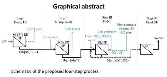
2. Process Description

Figure 1 depicts the proposed three-stage selective-separation process. The aim of the first separation step is to alter the ratio between the total hardness (i.e., the sum of Mg2+ and Ca2+, and to a lesser degree Sr2+) and the sulfate concentrations in seawater from the typical ~2 (eq/eq) prevailing in raw seawater to ~1.1 in the retentate of this membrane filtration step. This step, carried out in this work by a dense ultrafiltration membrane (GH series membrane, manufactured by GE), was performed to allow for efficient washout of monovalent ions in the 3rd diananofiltration (dia-NF) step, which otherwise is impeded by an electro-neutrality gap that is bridged by Cl ions, as elaborated in Tang et al. [14]. The aim of the second (optional) NF step was to increase the Mg2+ concentration in the retentate flowing to it from the 1st step and to increase the ratio between the mass of divalent and monovalent ions. The higher the Mg2+ concentration and the mass ratio of Mg2+ to either Na+ or Cl, the lower the required volume of costly low-TDS water for rinsing out the monovalent ions in the 3rd step (i.e., DiaNF step). The NF step is defined in this work as optional, because concentrating the Mg2+-rich brine in this step requires the application of antiscalants (AS) to prevent precipitation of gypsum and fouling of the NF membrane, which in this process are carried over to the final Mg2+-rich solution and thus also to the drinking water. If antiscalants (despite appearing at minute concentrations and being of food-grade quality) are undesirable, the process can be performed such that the retentate of the 1st step is pumped directly to the DiaNF (3rd) step. Such operation results in higher production costs but also with product water devoid of antiscaling chemicals. The DiaNF step utilizes low-TDS water obtained from the RO step of the desalination plant (prior to post treatment) as diluent, to wash out unwanted species (e.g., B, Cl and Na+) from the Mg2+-rich product solution, in a counter current mode. Counter current diafiltration (also termed Closed Loop Cascade Diafiltration [16]), as opposed to co-current diafiltration, recycles the permeate as a diluent, instead of using a fresh diluent at each cycle [17]. More specifically, the diluent in the first cycles is the permeate solution generated in the final DiaNF cycles. In other words, the permeate streams of the last DiaNF cycles are re-used to wash out the more concentrated feed water of the initial DiaNF steps. An additional step, i.e., final UF filtration, is optionally performed on the brine of the DiaNF (3rd) step with the aim of removing seawater microorganisms prior to injecting the Mg2+ rich solution to the desalinated water.

3. Materials and Methods

Two segments of the process were examined empirically in this work: (1) a two-step process, starting from the dense UF step aimed at reducing the TH/SO4 ratio of seawater which is followed by a DiaNF step applied on the retentate of the dense UF step; and (2) a three-step process in which a similar dense UF step was applied, followed by a NF step on the retentate of the dense UF step and DiaNF on the retentate of the NF step. Both processes are followed by a final UF step, whose purpose is to remove microorganisms, and possibly (depending on the AS molecular weight and the UF membrane used) to also remove the antiscalant agent. This polishing step was not examined experimentally in this work.
Dense UF step: 200 L Mediterranean coarsely-filtered (20 μm) seawater was used as feed to the UF step, which was performed using a GH4040F30 membrane (GE). Operational conditions: 15 bar external pressure and 20 ± 2 °C.
NF step: A synthetic solution, simulating the retentate produced in the dense UF step at 80% recovery ratio (RR) was used as feed to the NF step applied with a DLF1021 membrane (GE). In this case the applied pressure was 25 bar and the temperature 20 ± 2 °C.
DiaNF step: this step was examined in the two investigated process alternatives: first, it was fed with ~60% recovery ratio (RR) retentate of the dense UF step (i.e., avoiding Step II shown in Figure 1); next, it was fed with synthetic solution, mimicking ~80% RR retentate of the NF step following the 60% RR dense UF step (i.e., implementing both Step I and Step II). The experiments were conducted at 20 ± 2 °C and 25 bar external pressure. In the first DiaNF experiment, distilled water was used as diluent in all six DiaNF cycles. Thereafter, a counter-current DiaNF operational mode was conducted, i.e., the permeate streams of the last three cycles produced in the first DiaNF step were used as diluent of the following first three DiaNF cycles. In the last three DiaNF cycles of the counter-current application, distilled water was used as diluent.

4. Results and Discussion

4.1. Dense UF Step

The concentration ratio between total hardness and sulfate concentrations (in eq/eq units) and the mass ratio between Na+ and Mg2+ and between Cl and Mg2+ in the retentate of the 1st (dense) UF step are shown in Figure 2 as a function of the recovery ratio. Figure 2 shows that the divalent cations to sulfate ratio in the retentate dropped from ~2:1 in raw seawater to slightly above 1:1, as required, at RR of ~80% and also that the mass ratio between the monovalent ions and Mg2+ dropped considerably. At RR of 80% the average TH:SO42− ratio was 1.16 eq/eq. It was shown before [14,15] that reducing the TH:SO42− ratio in the retentate to ~1 allows washing most of the monovalent mass out of the retentate in the ensuing diaNF step. The results obtained by using the GH membrane in this step were significantly better than the ones reported previously by using a Nadir NP030 type membrane (see [14]). The latter also required a much higher pressure (40 bar) and much higher RR (90%) and even more importantly, the minimum TH:SO42− ratio attained with the Nadir NP030 membrane was not lower than 1.3:1. As a result of the high pressure and the high RR required with the latter membrane, the cost of the process increased considerably. In addition, since sulfate rejection of Nadir NP030 membrane was lower than that of the GH membrane used in the current work, the final Cl to Mg2+ mass ratio in a previous work [14], could not be reduced below 0.6 (g/g). The application reported here is therefore more feasible and cost effective than the one reported in Tang et al. [14]. Table 1 shows that the SI (Saturation index, i.e., log(IAP)–log(K’sp), where IAP stands for ion activity product), value for CaSO4(s) calculated in the retentate. As shown in Table 1, the SI values were negative throughout the run, regardless of the RR applied, implying that no gypsum precipitation and membrane scaling should be expected in this application (CaCO3(s) precipitation was prevented by the addition of 0.5 meq/L HCl to the raw seawater). The retentate obtained at 80% RR consisted the feed solution to the following NF step.

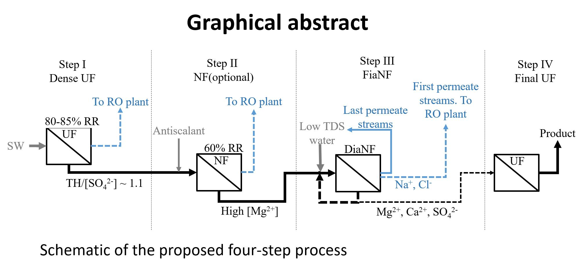
4.2. NF Step (2nd Step in Figure 1)

Table 2 shows the results obtained in the second step of the process (NF), i.e., the characteristics of the retentate obtained as a result of applying the NF step on the retentate of the preceding dense UF step (RR = 80%). The SI calculated for CaSO4(s) at the high RR values was positive but below 0.4 for RR of 65%, indicating that a properly selected antiscalant can enable prolonged operation without chemical scaling concerns.
Since the SI values for CaSO4(s) in the retentate of the NF step were positive (Table 2), an (counter-gypsum fouling) antiscalant was added to the feed of the NF step. The antiscalant dosage was set at 5 mg/L of (final volume) retentate. As expected, the NF step considerably elevated the retentate divalent ions concentrations (Mg2+, Ca2+, SO42−) while keeping the monovalent ion concentrations roughly constant. Therefore, the [Na+] to [Mg2+] and [Cl] to [Mg2+] ratios in the retentate reduced with the recovery ratio applied. Another important outcome of applying the NF step was the elevation of Mg2+ concentration, which led to a reduced volume of required retentate to be further treated in the process, and particularly (from the cost standpoint) to reduced volume of diluent, required in the following diaNF step.

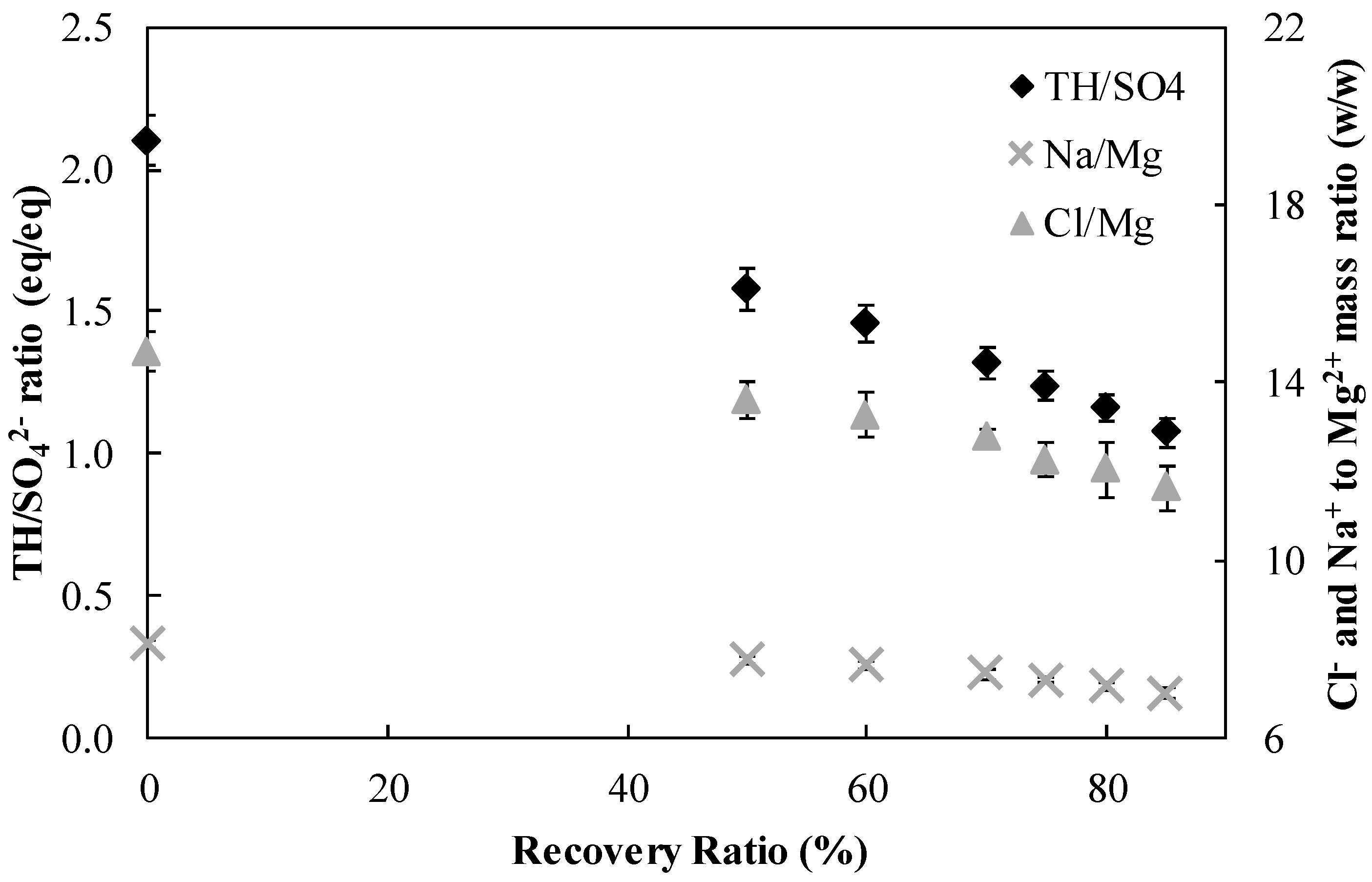
4.3. DiaNF Step (3rd Step in Figure 1 and the Last Step in the Presented Three-Step Process)

The DiaNF step of the three-step process was fed with the retentate of the 2nd step (NF at ~60% RR). The results, listed in Table 3, show that when distilled water was used as the diluent, an almost proportional dilution decline was obtained in the monovalent ion concentrations, while the divalent ion concentrations dropped only slightly (apart from SO42−, that did not drop at all, since its rejection by the NF membrane was ~100%). Thus, the Mg2+, Ca2+ and SO42− concentrations remained considerably high in the final DiaNF retentate. Accordingly, the [Na+] to [Mg2+] and [Cl] to [Mg2+] ratios dropped to very low values in the final (product) solution. More specifically, according to Table 3, for addition of 20 mgMg/L to desalinated water the Na+ and Cl addition would be 3.0 and 3.6 mg/L, respectively, after 6 DiaNF cycles. Table 4 shows similar results, only in this case a counter-current operation was conducted, i.e., the permeate solution of the last three dilutions (of the first DiaNF experiment) were used as the diluent in the first three DiaNF cycles of this DiaNF batch. Table 4 shows that the [Cl] to [Mg2+] and [Na+] to [Mg2+] ratios were somewhat higher in the counter-current mode, but that they were still very low (0.27 and 0.19 g/g, respectively, representing 5.4 and 3.8 mg/L additions corresponding to 20 mg Mg/L addition). Considering the significant economic benefit of the counter-current approach and the slight difference in results, the conclusion was that unless there is an extreme restriction on the chloride and sodium concentrations, the counter-current approach should be implemented.
In addition to Cl and Na+ addition, a certain (small) antiscalant concentration is also unavoidably added to the desalinated water in the three-step process, as it remains in the final brine of the DiaNF step, which is the process product. Having said that, the antiscalant concentration in the drinking water is minimal, amounting to ~0.027 ± 0.001 mg/L in all the tested alternatives (assuming that the antiscalant is 100% rejected in the DiaNF step).

4.4. DiaNF Step (2nd Step of the Two-Step Process)

The two-step process (dense UF step followed by DiaNF step) was tested as an alternative under which no antiscalant is added throughout the process thereby no antiscalant is present in the final desalinated water due to the Mg2+ addition. In this case, the DiaNF step was fed directly with retentate of the 1st (dense UF) step (GH membrane, 80% RR) without an intermediate NF step. Under this scenario, the SI values for CaSO4(s) were negative throughout the filtration processes and the SI values for CaCO3(s) were similar to those in raw seawater. Table 5 lists the results of the 6-cycle DiaNF procedure. As expected, the final Mg2+ concentration in the product solution is considerably lower (~50% of the concentration obtained in the three-step process), and the ratios between the monovalent ions and Mg2+ are somewhat higher.
According to Table 6, the resulting chloride concentration after addition of 20 mgMg/L to desalinated water in the two-step alternative is slightly higher than in the three-step one. Furthermore, the Mg2+ concentration in the product water is considerably lower in the 2-step alternative, which means that the volume of process solution (i.e., brine flowing into the DiaNF step) would be much larger, leading to elevated diluent demand for the DiaNF step, hence a higher cost. Considering that the antiscalant used in the NF step is food grade and its concentration is very low, the 3-step process seems to be the more logical alternative.

5. General Design and Layout of a Process for Enriching Desalinated Water with 20 mgMg/L Using the Results from the 3-Step Process

The general design and related cost calculations assumed a 150 Mm3/year desalination plant, operative for 330 day/year. Design flow rate was thus ~19,000 m3/h. From Table 4 the Mg2+ concentration in the product of the GH–DL–DiaNF (three step) process is ~3560 mg/L, thus the dilution ratio between the Mg2+ rich solution and the finished desalinated water is 1 to 178 (m3/m3). Accordingly, the required daily volume of product solution is:
  454500 m 3   day 178 m 3 m 3 = 2550 m 3   Mg   rich   solution day
The DiaNF step can also be applied continuously, by applying either a feed and bleed mode, or a single pass mode [17]. It is acknowledged that the feed and bleed mode requires more pumps, valves and tubing and also a more complicated control. On the other hand, when a single pass mode is applied, in order to attain high efficiency of washout of monovalent ions, or in other words, efficient use of the diluent, multiple membrane vessels should be used and the diluent should be dosed to the feed of each element. Therefore, in both continuous alternatives, efficient diafiltration involves high capital expenses, high plant complexity, and sophisticated process operation. In contrast, diafiltration can be applied in batch mode. In this alternative, the diluent is continuously added to the feed tank, from which the mixed solution is pumped to the NF membrane. Therefore, the quality of the feed to the process changes with time. Naturally, a batch mode operation is simpler to control and to operate, it involves lower capital costs but higher energy demand, unless pressure tanks are used [19]. Finally, it should be noted that the lab results reported in this work were attained by operating the DiaNF step in a batch mode. Thus, in order to be compatible with the quoted results, a batch mode operation was chosen for the assessment of the plant general design and process cost. To sum up, the process (dense-UF–NF–DiaNF–UF) discussed here is applied in part continuously (the dense-UF step, the NF step and also the final UF step applied on the final product solution) and in part semi-batch-wise (the DiaNF step in which the diluent is applied continuously but the retentate volume remains constant). All the calculations hereinafter were conducted for storage tank sizes required for 12 h of hydraulic retention time or for a DiaNF batch operation duration of 12 h. To change for a different design, e.g., in case 6 h retention time is chosen, the size of the tanks should be reduced by a factor of 2, and so forth. Note that the flowrates within the process remain the same, irrespective of the chosen storage retention time.

5.1. Process Sequence

The dense-UF step and the NF step (1st and 2nd steps in Figure 1) operate at continuous mode, thereby constantly producing the retentate, which, together with the diluent, are used as feed to the DiaNF step (3rd step in Figure 1). In contrast, the DiaNF step is operated in a semi-continuous mode with respect to the retentate: Each day 2500 m3 of rich Mg2+, Ca2+ and SO42− product solution are produced and separated into two batches of 1250 m3. The NF retentate and the diluent are fed to the DiaNF step, from which the permeate stream is constantly removed and the produced DiaNF retentate is constantly recirculated. By the end of this batch step, six dilution cycles have been performed and the DiaNF retentate contains the required low Cl and Na+ concentrations, while the Mg2+ concentration remains almost constant. This final retentate of this step constitutes the product solution.
Figure 3 shows a scheme of the various steps applied in the process and the corresponding flowrates and tank sizes. The DiaNF step is operated at counter current mode and is thus divided into two sub-stages: in the first sub-stage (Figure 3a), the diluent is the permeate of the previous DiaNF steps (the last three permeate streams, characterized by relatively low TDS). In the second sub-stage, RO permeate (obtained from the desalination plant just after the 1st membrane separation step) is used as the diluent (Figure 3b). The total volume of the diluent used in each sub-stage is three times higher than the final brine volume, i.e., 3 × 1250 m3 = 3750 m3. In order to complete each batch within 12 h, each sub-stage operates for 6 h. Therefore, the diluent flowrate should be 3750 m3/6 h = 625 m3/h. Such operation results in completion of each dilution cycle in two hours (1250 m3 fed at a flowrate of 625 m3/h). To achieve the best dilution effect the flowrate of the DiaNF permeate should be similar to the flowrate of the diluent. As mentioned, in the counter current mode, the first sub-stage of the DiaNF step uses three different diluent solutions: the permeate streams produced in the 4th, 5th and 6th DiaNF cycles of the previous batch. Therefore, the diluents for the first sub-stage are supplied out of three separate tanks (alternatively, they can be supplied out of one tank divided into three parts, each one at a volume of 1250 m3, denoted Tank Figure 3a–c). For this aim, the permeate streams flowing out of the 4th–6th DiaNF cycles are collected in these separate tanks. Note that the volumes calculated here are the required solution volumes, while the tanks’ volume should be somewhat bigger (for example, T1 should have a capacity of ~1500 m3 for holding the 1250 m3 feed to the DiaNF step).
Considering the process shown in Figure 3a, it can be concluded that after 6 h the three parts of tank T3 are empty, while the feed tank of the DiaNF step (denoted T1) contains 1250 m3 of brine, at the composition corresponding to the fourth row (Cycle #3) in Table 4. This brine undergoes now three additional DiaNF cycles, in which low TDS RO permeate is the diluent (Figure 3b). The flowrates in this stage are similar to those in the first stage. However, since the diluent’s composition in this sub-step is constant, and since it is produced continuously by the desalination plant, the diluent tank in this stage can be relatively small. The daily required volume of RO permeate (i.e., in two DiaNF batches) is 2 × 3 × 1250 m3 = 7500 m3.
At the end of the second DiaNF stage, the product, i.e., 1250 m3 of Mg2+-rich and almost devoid of monovalent impurities, is pumped rapidly to a large tank (denoted T4), which serves as the product storage tank, from which the solution is injected to the final UF stage and from there straight to the desalinated water product.
While T1 operates as the feed tank to the DiaNF step (as described above), the brine produced in the preceding NF step is fed to another tank, denoted T2, as shown in Figure 3c. At the end of each batch, the functions of T1 and T2 are switched.
All process steps are listed in Table 7. To sum up, two 1250 m3 tanks (T1 and T2) are required for receiving the NF brine and feeding the DiaNF step, intermittently, for periods of 0.5 day. Another 3750 m3 tank (T3) is divided into three 1250 m3 (partitioned) sub-tanks, which receive DiaNF permeate streams and then used for pumping the solutions for the purpose of monovalent ions washout in the DiaNF step. The two usages of tank T3 (i.e., receiving permeates and supplying diluent) change intermittently each 6 h. Another small tank stores the RO permeate. Finally, a large product storage tank is required, T4, at an estimated volume of 3500 m3.

5.2. Evaluation of the Number of Membranes Required in the UF–NF–DiaNF Steps

Dense-UF (Membrane: GH) Step

According to the RR of each step (80% and 60% in the dense-UF (GH) and NF steps, respectively), and the required daily volume of NF brine, the required feed flowrates to each membrane step were calculated. For example, 30,500 m3 feed/day are required in the dense-UF step. Accordingly, the dense-UF step will produce ~24,000 m3 permeate/d and ~6100 m3 brine/day. According to manufacturer data, the permeate flux of an 8″ GH membrane (GH8040F30, under standard conditions) is 28.0 m3/day. The required conditions involve higher divalent ion concentrations, and therefore the membrane flux is assumed to be lower than the one reported by the manufacturer. Based on lab results, the flux was assumed to be ~78% of the manufacturer data. In addition, it was assumed that the permeate flux remains approximately constant during the process, a reasonable assumption since the feed composition hardly changes. Accordingly, the number of membranes required in the dense-UF step is 1100. The size of each 8″ pressure vessel is ~0.25 × 0.25 × 1.5 m3. On average, the recovery ratio on each element is ~15%. Thus, five membranes are placed in series inside the pressure vessel, i.e., each train has five 8″ elements, i.e., train length of ~8.3 m. Assuming that a plant comprises 12 pressure vessels in each vertical array, the number of vessels in each horizontal array is 19 (since 1100/(12 × 5) = 18.6). The size of this plant is thus: height × width × length = (0.25 × 12 × 110%) × (0.25 × 19 × 110%) × (8.3 × 110%) = 144.5 m3 (note that the size was enlarged by a safety factor of 1.1 in each dimension). Table 8 details the values calculated in a similar way for the three steps of the process. The values were calculated under the following assumptions: (1) The average recovery of a single DL element is 11%. This figure is based on empirical results, showing RR of between 14.5% (first element) and 8.5% (last element); (2) 12 pressure vessels in each vertical array; (3) 10% safety factor for each plant dimension (L, W, H).

5.3. Cost Assessment

The cost of the three-step process, operated for the enrichment of desalinated water with 20 mg Mg/L was assessed. The concentration of the Mg2+ source solution (product solution attained after six DiaNF cycles) was adopted from the experimental results presented in this study (Table 4). The operational conditions of each of the steps (i.e., pressures and recovery ratios) were adopted from the experimental conditions and their relevant results. The operating expenses (OPEX) were estimated by considering the costs associated with the following: electricity demand for applying the required pressures in the four membrane steps including the UF pretreatment (i.e., UF, GH, NF and DiaNF); antiscalant demand (dosed only in the NF step); the cost of RO permeate used as the diluent in the DiaNF step; the cost of acid (HCl) dosed to the NF feed; and the cost of membrane replacement. OPEX calculations were carried out under the following assumptions: The electricity cost was assumed at 0.0721 $/kWh [20]; high-pressure pumps efficiency: 90%; antiscalant cost of $2000 per ton; pressure applied in the pretreatment UF step was estimated at 1.2 bar; cost of 1st pass SWRO permeate (prior to the post-treatment step) used as diluent was estimated at $0.5 [21]. Similarly, the DiaNF permeate streams collected and re-used as diluents in the counter-current alternative were considered free of charge. Further assumptions: HCl cost $70 per ton, membrane lifespan 7 years and membrane unit cost $700.
CAPEX related to the three-step process was evaluated based on the estimation that an NF or dense UF plant erection costs $2500 per m3 feed per h [13]. The feed to each process step was calculated and the total CAPEX was normalized per m3 of desalinated product water assuming 6% interest, 20-year serviceable lifespan and RO desalination plant capacity of 150 Mm3 per year. Additional 50% capital cost was assumed to be attributed to pressure tanks required in the DiaNF process.
The overall operational cost of adding 20 mg Mg/L by applying the three-step process was assessed at 0.0105 $ m−3 desalinated water (Table 9). The main OPEX components are the energy demand and the cost of the diluent, comprising 46% and 51% of the OPEX, respectively. Considering that adding the NF step results in reduced requirements for diluent volume and energy, it transpires that from the economic point of view, the three-step process is the more advantageous approach.
Detailed capital expenses (CAPEX) are not presented in this paper because they are very site specific and also largely depend on the choice of the batch retention time. Since the size of the various components are presented, readers can calculate their own capital expenses. Nevertheless, our calculations show that CAPEX constitutes roughly between 35% and 60% of the operational expenses (OPEX). Accordingly, the cost of supplying desalinated water with 20 mg/L of magnesium using the described process ranges between $0.0142 and $0.0168 per m3 of desalinated water.

6. Conclusions

  • Results from operation of a new three-step (plus UF polish) process are presented for separating divalent ions from seawater with the purpose of elevating the Mg2+ concentration of the product water of seawater desalination plants.
  • The first process step is carried out by passing seawater through a dense UF membrane with the purpose of rejecting sulfate and establishing a ratio of 1.1 to 1 between divalent cations and divalent anions in the retentate obtained at ~80% recovery.
  • The second and third steps are based on subjecting the retentate of the first step to nanofiltration and diananofiltration, respectively, with the goal of both elevating the Mg2+ concentration and reducing the monovalent ions concentration to low concentrations.
  • A general design is presented for a process in which the 1st and 2nd steps are operated continuously and the third (DiaNF) is operated semi-continuously with 12 h cycles.
  • The experimental results show that applying 3-step the process results in a product solution characterized by Mg2+ concentration of ~3700 mg/L along with much lower Cl and Na+ concentrations. As a result, the addition of 20 mg/L of Mg2+ to desalinated water will result in Cl and Na+ concentration increase of 5.4 and 3.8 mg/L, respectively.
  • The overall cost of the three-step process for adding 20 mg/L of Mg2+ to desalinated water was estimated at between $0.0142 and $0.0168 per m3 of desalinated water.

Author Contributions

O.L., S.C.N.T. and L.B. conceived and designed the experiments; S.C.N.T. performed the experiments; O.L., S.C.N.T. and L.B. analyzed the data; O.L., S.C.N.T. and L.B. wrote the paper.

Funding

This research received no external funding.

Conflicts of Interest

The authors declare no conflicts of interest.

References

  1. Cotruvo, J.B.J. (Ed.) Calcium and Magnesium in Drinking Water: Public Health Significance, 1st ed.; World Health Organization: Geneva, Switzerland, 2009. [Google Scholar]
  2. Dreizin, Y. Ashkelon seawater desalination project—Off-taker’s self costs, supplied water costs, total costs and benefits. Desalination 2006, 190, 104–116. [Google Scholar] [CrossRef]
  3. Birnhack, L.; Voutchkov, N.; Lahav, O. Fundamental chemistry and engineering aspects of post-treatment processes for desalinated water—A. Review. Desalination 2011, 273, 2709–2716. [Google Scholar] [CrossRef]
  4. Isreali Water Authority. Available online: http://www.water.gov.il/HEBREW/PLANNING-AND-DEVELOPMENT/DESALINATION/Pages/default.aspx (accessed on 29 July 2018).
  5. Birnhack, L.; Fridman, N.; Lahav, O. Potential applications of quarry dolomite for post treatment of desalinated water. Desalin. Water Treat. 2009, 1, 58–67. [Google Scholar] [CrossRef]
  6. Greiserman, M.; Hasson, D.; Semiat, R.; Shemer, H. Kinetics of dolomite dissolution in a packed bed by acidified desalinated water. Desalination 2016, 39–47. [Google Scholar] [CrossRef]
  7. Derco, J.; Luptáková, A.; Dudáš, J.; Vrabeľ, M. Recarbonization of drinking water in fluidized-bed reactor. Chem. Pap. 2017, 71, 1771–1779. [Google Scholar] [CrossRef]
  8. Lahav, O.; Nativ, P.; Birnhack, L. Dolomite dissolution is not an attractive alternative for meeting Ca2+, Mg2+ and alkalinity criteria in desalination plants’ post treatment step. Desalin. Water Treat. 2018, 115, 194–198. [Google Scholar] [CrossRef]
  9. Birnhack, L.; Lahav, O. A new post-treatment process for attaining Ca2+, Mg2+, SO42− and alkalinity criteria in desalinated water. Water Res. 2007, 41, 3989–3997. [Google Scholar] [CrossRef] [PubMed]
  10. Telzhensky, M.; Birnhack, L.; Lehmann, O.; Windler, E.; Lahav, O. Selective separation of seawater Mg2+ ions for use in downstream water treatment processes. Chem. Eng. J. 2011, 175, 136–143. [Google Scholar] [CrossRef]
  11. Birnhack, L.; Nir, O.; Lahav, O. Establishment of the underlying rationale and description of a cheap nanofiltration-based method for supplementing desalinated water with magnesium ions. Water 2014, 6, 1172–1186. [Google Scholar] [CrossRef]
  12. Lehmann, O.; Eckhaus, O.; Lahav, O.; Birnhack, L. Replenishing Mg(II) to desalinated water by seawater nanofiltration followed by magnetic separation of Mg(OH)2(s) Fe3O4 particles. Desalin. Water Treat. 2016, 57, 19903–19916. [Google Scholar] [CrossRef]
  13. Nativ, P.; Birnhack, L.; Lahav, O. DiaNanofiltration-based method for inexpensive and selective separation of Mg2+ and Ca2+ ions from seawater, for improving the quality of soft and desalinated waters. Sep. Purif. Technol. 2016, 166, 83–91. [Google Scholar] [CrossRef]
  14. Tang, S.C.N.; Birnhack, L.; Nativ, P.; Lahav, O. Highly-selective separation of divalent ions from seawater and seawater RO retentate. Sep. Purif. Technol. 2017, 175, 460–468. [Google Scholar] [CrossRef]
  15. Tang, S.C.N.; Birnhack, L.; Cohen, Y.; Lahav, O. Selective separation of divalent ions from seawater using an integrated ion-exchange/nanofiltration approach. Chem. Eng. Process. Process Intensif. 2018, 126. [Google Scholar] [CrossRef]
  16. Foley, G. Closed-Loop Cascade Diafiltration. In Encyclopedia of Membranes; Drioli, E., Giorno, L., Eds.; Springer: Berlin, Germany, 2016. [Google Scholar]
  17. Kovacs, Z. Continuous Diafiltration: Cocurrent and Countercurrent Modes. In Encyclopedia of Membranes; Drioli, E., Giorno, L., Eds.; Springer: Berlin, Germany, 2016. [Google Scholar]
  18. Appelo, C.A.; Postma, D. Geochemistry, Ground Water and Pollution, 2nd ed.; Appelo, C., Postma, D., Eds.; CRC Press: London, UK, 2005. [Google Scholar]
  19. Kovács, Z. Batch Diafiltration. In Encyclopedia of Membranes; Drioli, E., Giorno, L., Eds.; Springer: Berlin, Germany, 2016. [Google Scholar]
  20. U.S. Energy Information Administration, Electric Power Monthly 2017. U.S. Department of Energy. Available online: http://www.eia.gov/electricity/monthly/pdf/epm.pdf (accessed on 3 August 2017).
  21. Ziolkowska, J.R. Desalination leaders in the global market—Current trends and future perspectives. Water Sci. Technol. Water Supply 2016, 16, 563–578. [Google Scholar] [CrossRef]
Figure 1. Schematic of the proposed three-step process with a final UF polishing step.
Chemengineering 02 00041 g001
Figure 2. Average retentate characteristics obtained in the dense UF step as a function of recovery ratio (membrane: GH; n = 3).
Chemengineering 02 00041 g002
Figure 3. Schematic of the main plant components, the tanks used in each step, their sizes and the required flowrates. The first and second DiaNF sub-stages (3rd step of the proposed process) with intermittent diluent of DiaNF permeates and RO permeate, respectively, are shown in (a,b), respectively. (c) shows the dense-UF–NF process operated in parallel (1st and 2nd steps of the proposed process).
Chemengineering 02 00041 g003
Table 1. CaSO4 saturation index (SI) in the retentate produced in the dense UF step as a function of the recovery ratio, calculations made using PHREEQC interactive 3.3.10-12220 [18].
GH Step BrineSI
RR (%)Gypsum (CaSO4)
0 (raw seawater)−0.48
50−0.33
60−0.29
70−0.22
75−0.18
80−0.13
85−0.08
Table 2. Average (n = 3) results from passing the retentate of the dense UF step (GH membrane, 80% RR) through a nanofiltration membrane (DLF1021) at P = 15 bar and 20 ± 2 °C. AS used: Genesys CAS.
RRClCa2+K+Mg2+Na+SO42−TH/SO4Na/MgSI of Gypsum
g/Lmg/Lmg/Lmg/Lmg/LmgS/Leq/eqg/g
GH 80RR27.11 ± 0.11611 ± 9588 ± 81949 ± 3414,458 ± 932758 ± 481.11 ± 0.0017.42 ± 0.102−0.16 ± 0.009
4026.96 ± 0.13925 ± 14636 ± 143010 ± 2915,408 ± 2464440 ± 491.06 ± 0.0125.12 ± 0.0820.12 ± 0.005
5028.63 ± 0.211076 ± 2660 ± 123537 ± 4115,800 ± 1975349 ± 851.03 ± 0.0214.47 ± 0.1.020.20 ± 0.005
5529.20 ± 0.111167 ± 23669 ± 173879 ± 5016,007 ± 3405895 ± 821.02 ± 0.0094.13 ± 0.0950.27 ± 0.005
6029.36 ± 0.151293 ± 35686 ± 174303 ± 7016,294 ± 3716525 ± 971.03 ± 0.0063.79 ± 0.0790.33 ± 0.012
6529.34 ± 0.181439 ± 26707 ± 174822 ± 4416,648 ± 2797366 ± 751.02 ± 0.0053.45 ± 0.0570.39 ± 0.009
Table 3. Results of applying six DiaNF cycles on the retentate obtained from the NF step (DL membrane, ~60% RR) derived from the retentate produced in the dense UF step (GH membrane, 80% RR). External pressure: 25 bar; diluent: Distilled water; AS used: Genesys CAS; Temperature 20 ± 2 °C.
CycleClCa2+K+Mg2+Na+SO42−TH/SO4Cl/MgNa/Mg
g/Lmg/Lmg/Lmg/Lmg/LmgS/Leq/eqg/gg/g
026.971111631426915,98057691.136.323.74
113.309463063963743557521.043.361.88
27.10
33.9085196.73757226955861.011.040.60
42.0980751.43711130756220.980.560.35
51.2275827.9356182154610.970.340.23
60.6879115.9384757959350.960.180.15
Table 4. Results of applying six DiaNF counter current cycles on the retentate obtained from the NF step (DL ~60% RR) applied on the brine produced in the dense UF step (GH 80% RR). Pressure: 25 bar; diluent: Distilled water and DiaNF permeate; AS used: Genesys CAS; Temperature 20 ± 2 °C.
CycleClCa2+K+Mg2+Na+SO42−TH/SO4Cl/MgNa/Mg
g/Lmg/Lmg/Lmg/Lmg/LmgS/Leq/eqg/gg/g
025.68 1171587423414,74060201.086.073.48
113.89 10733454098841059521.053.392.05
28.04 9472003812486656191.032.111.28
34.93 9341223906296358261.011.260.76
42.82 846683743170756490.990.750.46
51.68 797393653103955920.970.460.28
60.97 76022356366155210.960.270.19
Table 5. Results of applying six DiaNF cycles (NF membrane: DLF1021) on the retentate obtained in the dense UF step (GH 80% RR). Operational conditions: Pressure 15 bar; diluent: Distilled water; Temperature 20 ± 2 °C.
CycleClCa2+K+Mg2+Na+SO42−TH/SO4Cl/MgNa/Mg
g/Lmg/Lmg/Lmg/Lmg/LmgS/Leq/eqg/gg/g
022.26640568215814,08028941.1610.326.52
111.565482981919725027641.076.023.78
26.235031681840397727241.043.392.16
33.544831011771227226791.012.001.28
42.07443621713139726460.991.210.82
51.2642640169387626090.980.740.52
60.7241128168358626600.960.430.35
Table 6. Results of applying six DiaNF counter current cycles on the retentate obtained in the dense UF step (GH 80% RR). Operational conditions: Pressure: 15 bar; diluent: Distilled water (last three cycles) and DiaNF permeate (first three cycles); temperature 20 ± 2 °C.
CycleClCa2+K+Mg2+Na+SO42−TH/SO4Cl/MgNa/Mg
g/Lmg/Lmg/Lmg/Lmg/LmgS/Leq/eqg/gg/g
020.74625553207312,21531001.0410.015.89
111.155923622036727030571.035.473.57
27.005512431953452929541.023.592.32
34.235381651974283030311.002.141.43
42.444971061871167429240.981.300.89
51.45467761812105028690.960.800.58
60.8745456180073128630.950.480.41
Table 7. Process stages. Details of the tanks used in each step at each time.
Time (h)NF StepDiaNF Sub-Stage #1 Feed StreamsDiaNF Sub-Stage #2Product Dosage to RO Permeate (after UF) from Tank
Brine Goes toBrineDiluentFeed *Permeate Goes to
0–6T1 at Qfrom T2 at 6Qfrom T3 at 6Q T4 at Q
6–12 T1 at Q from T2 at 6QT3 at 6QT4 at Q
12–18T2 at Qfrom T1 at 6Qfrom T3 at 6Q T4 at Q
18–24T2 at Q from T1 at 6QT3 at 6QT4 at Q
* DiaNF is fed also by RO permeate, from a specific (relatively small) tank.
Table 8. Calculated size of the proposed Mg-enrichment membrane plant.
ParameterUnitsDense UF Step (GH)NF Step (DL)DiaNF Step (DL)
Required feedm3/day30,440608829,223
Recovery ratio%8060
Produced permeatem3/day24,352365314,611 **
Produced brinem3/day608824352435
membrane permeate flux *m3/day21.918.718.7
Number of membranes 1116196784
Number of membranes in a train 565
Plant lengthm8.39.98.3
Plant widthm5.30.833.9
Plant sizem3144.527.4106.5
* 78% of manufacturer data for 8″ membranes, GH8040F30 and DL8040C-50P. ** 7306 m3 of permeate is stored for use in diluting in the next DiaNF.
Table 9. Operational costs of applying the three-step process for adding 20 mgMg/L to desalinated water using counter current mode, and either 4 or 6 DiaNF cycles.
ParameterCost ComponentProcess StepCost
10−2 $ m−3 Desalinated Water
OPEXenergyUF (GH)0.225
NF (DL)0.075
DiaNF0.187
sub-total0.486
diluentDiaNF0.538
UF stepsPre treatment0.018
antiscalantNF0.005
HClNF0.005
membrane replacementAll steps1.8 × 10−5
Total 1.053

