Energy Performance Analysis of a PV/T System Coupled with Domestic Hot Water System


1
College of Engineering, Design and Physical Sciences, Brunel University London, London UB8 3PH, UK
2
Faculty of Environmental Engineering, Wroclaw University of Science and Technology, Wybrzeze Wyspianskiego 27, 50-370 Wroclaw, Poland
*
Author to whom correspondence should be addressed.
ChemEngineering 2020, 4(2), 22; https://doi.org/10.3390/chemengineering4020022
Submission received: 20 December 2019
/
Revised: 14 February 2020
/
Accepted: 25 March 2020
/
Published: 30 March 2020
(This article belongs to the Special Issue Advanced Heat Exchangers for Waste Heat Recovery Applications)
Abstract
:In this paper, a standalone photovoltaics-thermal solar panel is modelled using the TRNSYS simulation engine. Based on this, it was explored how such a system can be comprised of thermal and electrical storage components to provide electricity and hot water for a dwelling in a warm location in Europe. Furthermore, it was investigated how, by cooling the temperature of the solar cells, the electrical power output and efficiency of the panel was improved. The performance of the system was also studied, and the amount that the solar panel was able to convert the solar energy into electricity was investigated. Through this, we discovered that when the temperature of the panel was reduced, on average, by 20%, the electrical power output increased by nearly 12%. Moreover, it was demonstrated that the modelled system can provide hot water under different solar radiation conditions and during all seasons of the year.
1. Introduction
With the ever-rising concerns regarding the environmental impacts related to greenhouse gas emissions of energy production, as well as the growing trend of increase in energy prices, the engineering industry is eager to find more sustainable and cheaper sources of energy. In this aspect, the focus on developing technologies that can harness and store renewable energy sources has been set as one of the most important areas of investment and research. In this regard, the use of solar energy, as being the most available renewable energy resource, has received very special attention during recent years.
Solar energy can be captured to produce thermal or electrical energy, through either photovoltaics or thermal solar panels. Having said that, the systems can also be combined together to generate both heat and electricity [1]. These technologies, which are mainly passive and require no power input from any source, can produce energy pollution and noise free. Nonetheless, and in spite of extensive developments of solar panels, the technology was found to have a very low module efficiency, and because of that, is yet to be implemented in global scale [2]. For instance, one of the major factors that prevents photovoltaics solar panels to generate electricity and lose efficiency is temperature [3]. According to Tan et al. [4], once the surface temperature of the solar panels hits 25 °C, the efficiency of the panel drops by nearly 0.5% for every degree of temperature increase.
This has followed several studies that have been conducted to look into the cause of this issue, and accordingly investigated that employing cooling techniques are crucial for obtaining valuable efficiency outputs from photovoltaics (PV) systems. Although there are various types of proposed cooling systems for PV systems, they can be categorized into two major types: active cooling, and passive cooling [5]. Active cooling, in simple terms, consumes energy to operate; while passive cooling does not require externally supplied energy. Instead, passive cooling employs natural conduction or convection to enable the extraction of heat.
Active cooling, on the other hand, draws energy from external sources to cool down the solar panel. Most of the methods employed in active cooling can be either based on air or water cooling [6]. The extracted energy can then be use used for another purpose, hence, improving the overall efficiency of the whole system. This means that the active cooling methods often lead to more power being produced, as well as more accessible energy.
Based on the above findings, it is of interest that in this paper, a comprehensive state of the art literature review was to be conducted. Furthermore, several comparisons will be made, and a system of photovoltaics solar panels will be modelled by using TRNSYS simulation software. From this, and through comparing the model with investigated studies, the model will be validated. Based on this, it will be discovered how the efficiency of a photovoltaics panel can be improved when an efficient thermal absorption system is in use. Moreover, it will be explored if the demand of a household in a hot environment, through days and nights over a year, can be supplied using a standalone photovoltaics-thermal panel that incorporates external electrical and thermal storage systems.
2. State of the Art Study
Figure 1 shows the main cooling methods employed for PV panels. As can be seen, it was discovered that cooling techniques of PV panels can be mainly divided into three major types: conductive, air, and water cooling.
It should be noted that these technologies mostly function based on conductive cooling techniques. In conductive cooling, the principal component of heat transfer from the PV system is conducted through conduction to a coolant fluid, such as air or water. This, for example, was demonstrated by Popovici et al. [8], where a PV system that incorporates an air-cooled heat sink was used. Experimental studies summarized that there can be about a 9% increase in electrical efficiency when a PV system with the heat sink is employed, as compared to case without a heat sink [9].
The water-based cooling methods, however, were also found to be comparatively efficient cooling techniques since water has a high thermal capacity. In one study carried out on the cooling of a PV panel, it was shown that the method helped not only to achieve a stable temperature of 30 °C, but also increase the overall efficiency about 20% [9]. Further modification of the water cooling system was made by incorporating a water trickling configuration. Observations made suggested that it was possible to achieve an increase in the relative output efficiency of about 15% [10].
Fakouriyan et al. [11] developed a model of a water-cooled PV/T system and illustrated how, by passing water underneath the surface of the solar panel, both hot water and cooling effect can be obtained. This model proved to improve the electrical efficiency of the panel by around 12%, significantly reducing the payback period of the system.
Kazem et al. [12], on the other hand, conducted a deep study into a water-based PV/T collector and reported that the electrical power performance of the solar panel can be improved by around 8% when water is circulated through a manifold under the surface of the panel. This study, which was conducted in one of the hottest regions of the Middle East, suggested a massive potential for the use of PV/T panels in a hot area and concluded that thermal characteristics and heat exchanger coefficient are important factors when looking into the design of such a system.
On the other hand, the use of phase change material (PCM) for cooling was also identified as an effective type of passive conductive cooling. The use of such a passive technology means that the heat is dissipated through the process of conduction without additional work involved [13,14]. It was discovered that with the appropriate type of PCM material, electrical efficiency increases of as high as 5% can be achieved [15].
Following the above findings, Peng et al. [16] in an experiment used ice to cool down the surface temperature of a PV panel and examined how this method can affect the overall electrical output. Through this study and by examining the performance of the panel, it was demonstrated that by using the cooling method, an overall efficiency increase of almost 7% can be achieved. Furthermore, a life cycle assessment for the cooled and non-cooled panels was conducted and it was found that in comparison, cooling of solar panels can lower cost and the payback period to 12.1 years, compared to 15 years, while increasing the operation and lifetime of the system.
Having shown that, Elminshawy et al. [17] managed to come up with a novel cooling system, which took advantage of using geothermal cooling to control the temperature of PV cells. In this experiment, a PV cooling system was constructed by using a heat exchanger that comprised of several pipes which were connected to a system with an air blower and buried under the ground. The heat exchanger was then connected to a channel that was placed under the panel surface. The configuration was designed in a way so that it can pass and generate cool air, by using a centrifugal fan that draws air from outside and sends it through the cold soil where the heat exchanger is placed. This resulted in successful cooling of the temperature of the panel by up to 13%, resulting in enhanced and increased power output of by nearly 14%.
Rajput et al. [18] came up with an innovative idea and designed a cylindrical pin fin heat sink to study the effect of cooling on a photovoltaic panel. In this study, a high intensity halogen lamp was employed to increase the surface temperature of a polycrystalline panel to an average of 85 °C. Through this method and by attaching the heat sink to the back surface of the panel, the overall surface temperature significantly dropped, and the power output was increased by nearly 10%.
Furthermore, Herrando et al. [19] built a numerical model of such a PV/T system and discovered that with a completely covered collector and a flow-rate of 20 L/h, 51% of the total electricity demand and 36% of the total hot water demand over a year can be covered by a hybrid PVT system. The PV/T technology proved to save 35% more CO2 over a lifetime of 20 years, when compared to PV-only systems.
Table 1 shows the summary of other studies which were conducted in regards to PV cooling, indicating the advantages and disadvantages of each method.
The use of heat pipe-based cooling systems was also found to be another effective method of cooling PV panels and has been the focus of several studies [24,25]. A cooling system that incorporates heat pipes takes advantage of both the convection and phase change phenomena of a cooling device at once, hence, improving the overall heat absorption and transfer from the PV cells. With this technology, the hot PV panel that faces the sun can be placed directly on a surface with several heat pipes. The heat from the PV is then absorbed and transferred onto a working fluid which is inside the heat pipe. This will then make the working fluid expand and evaporate, thus taking up the heat from the panel. Next, the vapor, which was created due to the evaporation of the working fluid, travels and releases the latent heat to a cooler section, where the heat sink or the condenser of the heat pipe is located. The heat sink can include a manifold to cool the heat pipe through air, water, or other cooling mediums [26]. The working fluid then completes the cycle by travelling back as a liquid through capillary action to the evaporator or the hot PV cells to repeat the process again. Heat pipe-based cooling systems can be used to achieve a more stable and rather uniform PV-T panel temperature [27].
Jouhara et al. [28] performed further investigations into this matter, took advantage of the heat pipe technology, and built a novel heat mat that can effectively take the waste heat away from the solar panel. In this study and as seen from Figure 2, a multi-channel flat heat pipe (heat mat) was connected to a cooling manifold and placed under the surface of a photovoltaics panel. In this configuration, the heat was absorbed by the heat mat and transferred through the heat pipe working fluid to the condenser section, which cooled down the whole system. This experiment managed to bring the surface temperature of the PV panel down by an average of nearly 30 °C, resulting in an increase of the electrical output efficiency by almost 15%. The technology was then implemented in a building which simulated a family house in Cardiff, UK, and it was illustrated that nearly 60% of the hot water demand of the dwelling can be produced, even during the days when the level of solar radiation was low. Furthermore, the system managed to supply about 55 W/m2 of electricity, while providing a thermal efficiency of almost 50%.
3. System Modelling
In this study, and to follow the above investigations, TRaNsient SYstem Simulation (TRNSYS) software was employed to develop and model a photovoltaics-thermal system. As Beckman et al. [29] explains, TRNSYS has been identified as one of the most important and complete solar energy system modelling and simulation softwares. The software includes several components or Types that can be connected to each other to develop a system. In this aspect, the output of a Type can be calculated and can be used as a function of the input to another component or be illustrated as the result of the simulation.
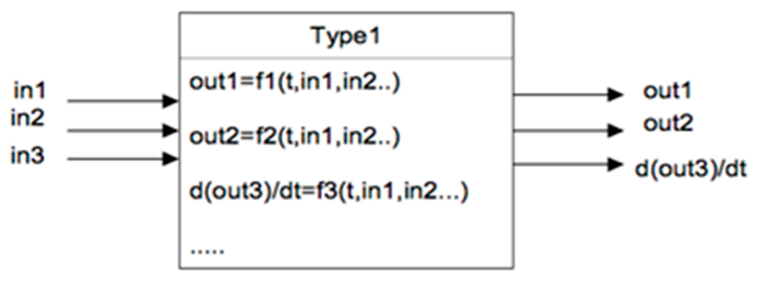
The principle behind TRNSYS is employing algebraic and first order differential equations to represent the physical mechanisms in software subroutines or Types along with a combined interface. The interface has two essential parts, which are input and output. Output quantities can describe physical measurement. First order derivatives vary with time in relation to the physical measurement. Each subroutine has a function relationship combining the input and output, as shown in Figure 3 [30].
The system module can be created by connecting the input and output components with each other, without concern for the connection complexity as this program is designed for solving the relative equations. Each physical component has a target to represent, attached to the input that was connected to a data file, to provide forcing function, printing plots, integrating, or interpolating data.
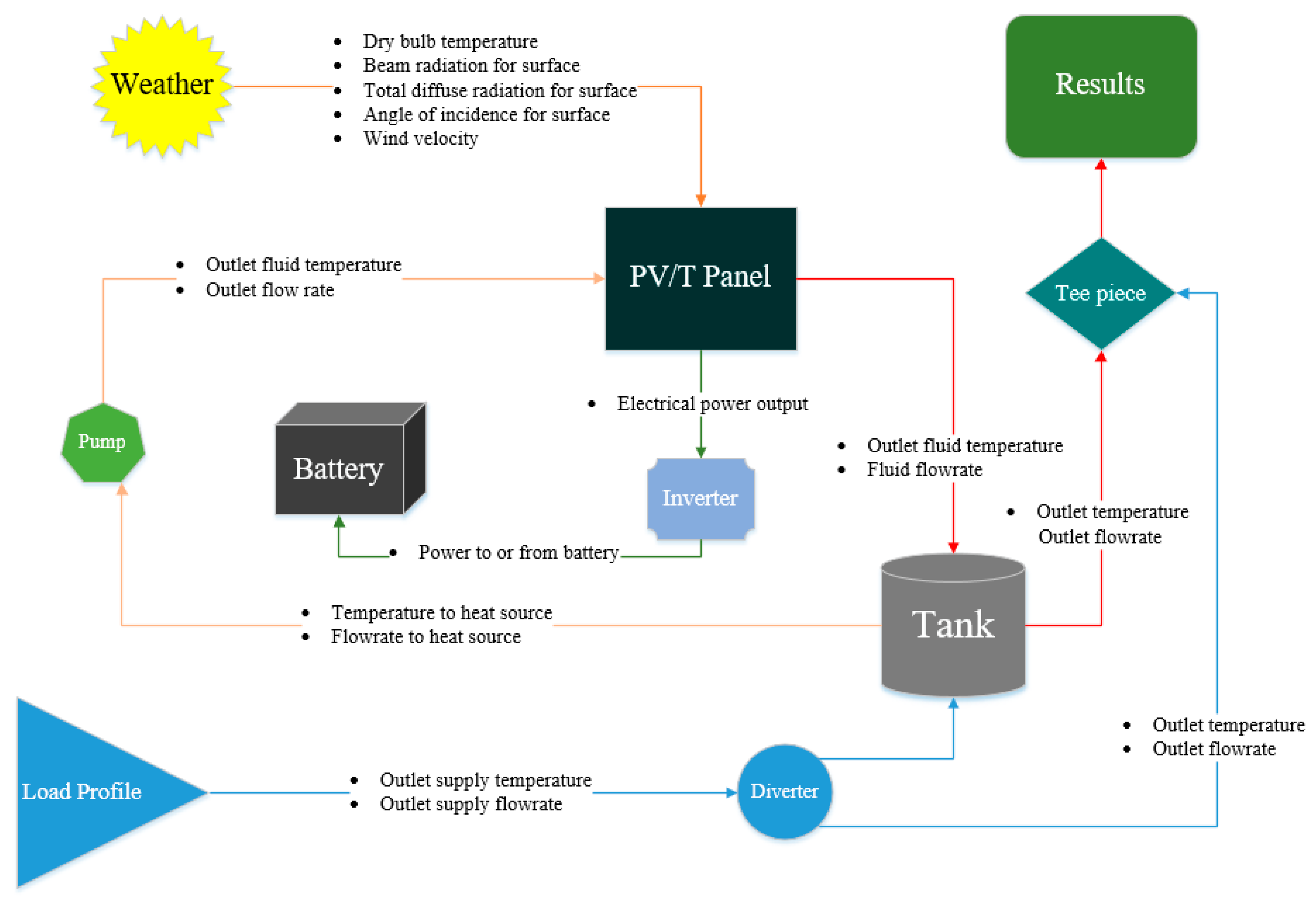
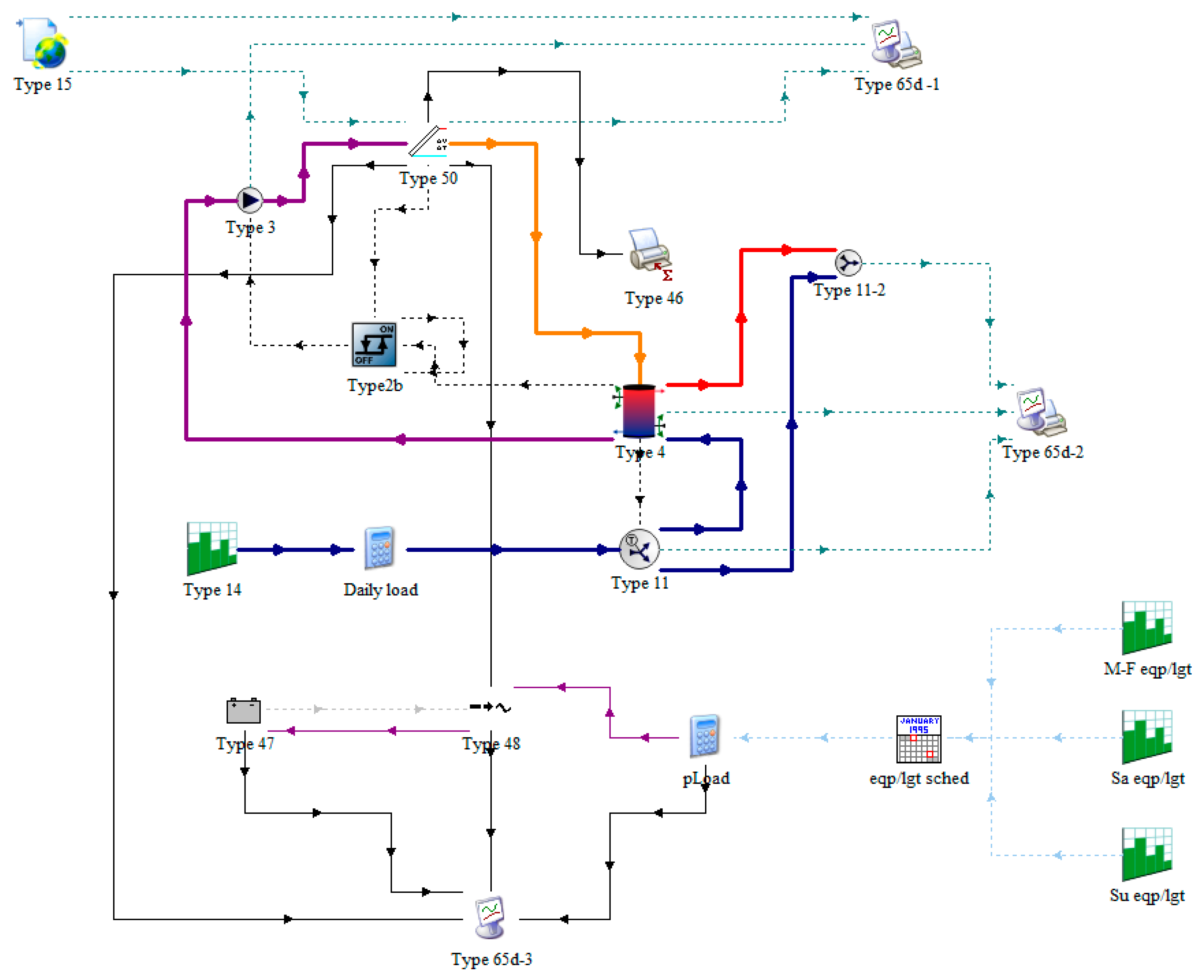
For this study, as shown in the Table 2, several Types were used to build and model the system. These Types were connected in a configuration so that the effect of cooling of the panel through water circulation can be indicated. As can be seen from Figure 4, the solar panel collects several data from Type 15 and Type 14, before producing electrical power and hot water outputs. The produced electricity from the panel is then guided to an inverter, which works as an electrical current convertor to and from Type 47. The hot water in this setup is instructed towards a hot water storage tank, which comprises an internal auxiliary power unit (Type 4) and works by delivering cool water to the pump and hot water to a tee piece. A tempering valve (diverter) was also implemented and placed after Type 14, to ensure a constant delivery of output temperature to Type 11.
As can be seen from Figure 5, the system is modelled in a way so that the generated heat can be taken away and stored in a thermal storage tank when cold water is passed through the panel. Following this, a controller is put in place to give order to the pump to deliver cold water from the tank to the panel with water at 20 °C temperature. This is to ensure that cold water is passed through the panel to absorb the waste heat.
The electrical power input to Type 48 is monitored to investigate if the produced electricity is sufficient to be directed to the auxiliary power unit to supply constant hot water from the tank. The examination will be conducted throughout the day and night and in all seasons of the year for a household of three in a hot location in Europe. The results of the simulation, in terms of the electrical and thermal performance, will be indicted by using Type 65.
In this regard, the installation will be simulated and tested in Madrid, Spain, using the Metronome weather data provided for this location. The reason for this selection was taken entirely on the basis that, as investigated, high temperature can negatively affect the performance of the solar panel and therefore, the choice of this location will allow us to investigate the effectiveness and performance of the technology and the system.
4. Estimations and Model Validation
It is estimated that the hot water demand of a family of three is about 200 L per day. This value is calculated by the amount of time each person takes showers and uses washbasins, which are assumed to be one time and four times per day, respectively. The hours at which water is consumed are indicated to be between 6 a.m. to 7 a.m. for two showers and three washbasin uses, between 2 p.m. and 4 p.m. for six uses of the washbasin, and between 8 p.m. to 10 p.m. for one shower and three uses of washbasin. The output temperature and demand unit of hot water was taken from the study performed by Castillo et al. [30], where it was indicated that the average household in Spain consumed around 144 L of water per person each day for shower and washing. The World Health Organisation (WHO) recommends that hot water should be stored and supplied at a minimum temperature of about 60 °C and therefore, the system must ensure the delivery of that [31].
The performance of the system was tested under different solar radiation for a duration of a year (8760 h) and the transient behaviour of the electrical output of the module was monitored. As explained by Khordehgah et al. [25], the electrical power output, thermal average output, and cooling effect of the panel can be defined as follows:
where, EL is the electrical output (E), I is the current, U is the voltage generated by the PV module, and A is the area of the panel (APV). QT is the amount of heat produced by the PV panel, ṁ is the coolant mass flow rate entering the system (water), Cp represents the specific heat capacity of water, and ΔT is the temperature difference of water between the collector inlet and outlet.
EEL = I.U/APV
QT = ṁ Cp ΔT
The PV cell temperature, Tc, is influenced by various factors, such as solar radiation, ambient conditions, and wind speed. It is well known that the cell temperature impacts the PV output current performance, and its time-variation can be determined. The PV cell temperature, as well as the whole PV solar panel temperature, can be computed from the following heat balance [32]:
where:
- TC: PV cell temperature.
- Cp_module: Thermal capacity of the PV module.
- t: time.
- Qin: Energy received due to solar irradiation.
- Qconv: Energy loss due to convection.
- Qelect: Electrical power generated.
The thermal energy transferred from the PV cell to the heat transfer fluid (HTF) is determined from the heat balance across the PV cell and HTF in terms of the heat transfer mechanisms: conduction, convection, and radiation, as follows.
The heat transfer by conduction is:
where:
- Tm: Module back surface temperature.
- Kpv: Thermal conductivity of PV cell.
- Lcell: Length of a PV cell.
- ΔT: Temperature difference Tc − Tm.
The heat transfer by convection is determined from
where:
- Qconvection: Energy due to convection.
- hwater: Heat transfer coefficient.
- Tf: Fluid temperature.
- ΔT: Temperature difference Tm − Tf.
The heat transfer by radiation is:
where:
- : Emissivity of PV cell.
- σ: Stefan–Boltzmann constant.
Equation (5) can be rewritten as follows:
where:
- mw: Water mass flow (HTF).
- : Specific heat of water.
- TfHx: Maximum temperature difference at the heat exchanger heat tubes.
The finite difference formulation is used to determine the heat transfer fluid temperatures at each element where the heat transfer fluid tube is divided into a number of thermal elements:
where:
- t: Time.
- δQ: Heat transfer per element.
- Tf_in: Fluid temperature at inlet.
- Cp: Water specific heat.
The thermal energy transferred from the PV cell to the heat transfer fluid (HTF) is obtained by:
where:
- QThermal: Energy from thermal process.
- TfHx+1: Fluid temperature at thermal element 1.
- ΔT: Temperature difference TfH+1 − Tf in.
The energy transferred to the heat transfer fluid is calculated from the integration of Equations (3)–(9) written for each element, dx, along the length of each tube.
It is worthwhile mentioning that the PV cell and panel temperature are influenced by different factors and, in particular, the ambient conditions such as the temperature, humidity, and wind speed, among other parameters. The back temperature, Tm, of the PV cell and PV panel can be calculated from the heat balance across the PV cell as follows:
where Tm is the module back-surface temperature, and TC is the PV cell temperature.
Qin = mCp_module∆T = mCp_module (TC − Tm),
It is assumed that Tm is equal to the surface temperature of the heat exchanger tubes welded to the solar PV cell/panel in close contact to the back surface of each of the PV cells.
The water is then passed into a thermal storage tank for heat storage. The total heat capacity of the medium at uniform temperature during a cycle with a temperature range difference () in the storage can be defined as:
where, and are the mass flowrate and the specific heat of water in this case.
In order to validate the system, the parameters in Table 3 are indicated, and the water output temperature from the simulation is compared with the mathematical results [19] and the model developed by Khordehgah et al. [25]. As shown in Figure 6, it was discovered that the simulation results, that were run for a weekday in July, closely match the model data.
5. Results and Discussion
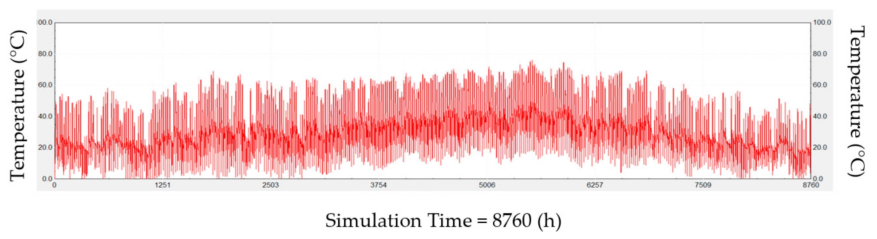
Comparisons of Figure 7 and Figure 8, indicated that the surface temperature of the solar panel reduced by about 20% on average when water was passed through the panel. Following this and as illustrated by Figure 9 and Figure 10, this resulted in an increase of the electrical output power by nearly 12%. This verified the investigated facts in the literature review and demonstrated how an increase in the cell temperature can affect the efficiency and power output of the panel.
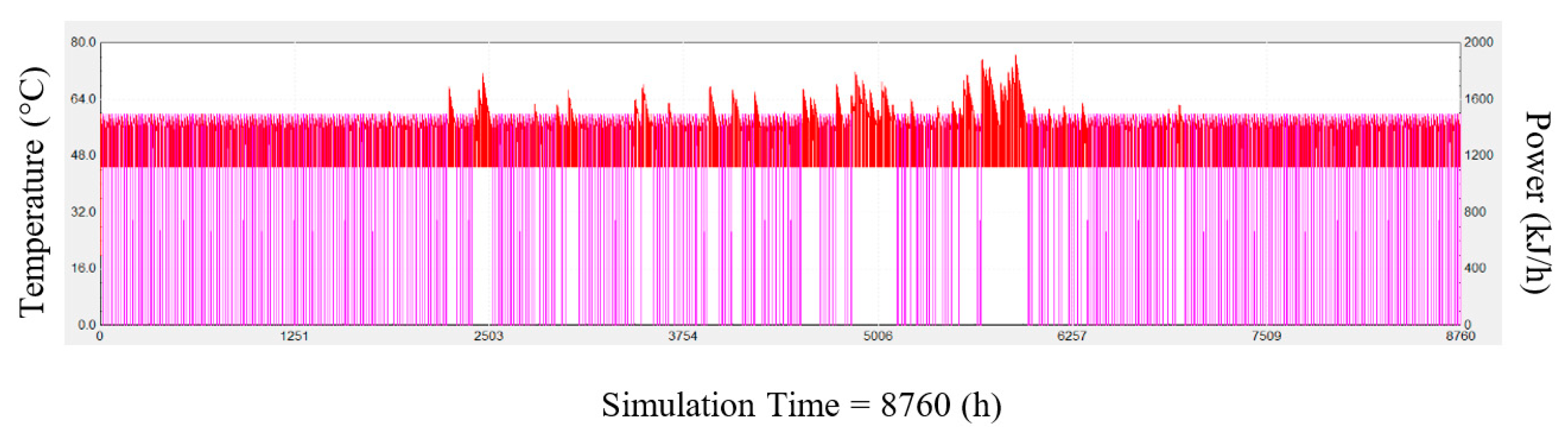
As shown by Figure 11, it was further discovered that the system can supply the required demand of hot water (red) to the dwelling; however, the auxiliary unit in the storage tank may be required to supply heat at a rate of 1500 kJ/h to keep the water temperature at 60 °C throughout the year. Having said that, it was also illustrated that the electrical power from the battery bank (purple) may be adequate enough to feed the auxiliary heating unit (heating the water in the storage tank to the set value), especially during the night and wintertime, when solar radiation is not sufficiently high enough.
6. Conclusions
In conclusion, a system of a PV/T solar panel, that can be used to produce electricity and hot water for a household in Spain, was modelled using TRNSYS software. It was investigated how, by cooling down the temperature of the PV cells, the electrical power output and efficiency of the panel can be improved. By looking at the current state of the technologies used for cooling photovoltaics solar panels, it was demonstrated that several technologies have been developed and experimentally tested that provide different efficiency increases. Through this and by comparing the results obtained from the simulation and experimental data, a system was modelled and verified, to investigate and examine the effect of cooling on the efficiency of the panel.
This was conducted by allowing water circulation to the panel and comparing the result of that to the case when this was not applied. The simulation results showed that when the temperature of the panel was reduced on average by 20%, the electrical power output increased by nearly 12%, confirming the findings in the literature review. Furthermore, it was indicated that the system is capable of providing hot water at the required amount throughout the year. However, input from an auxiliary power unit may be required to heat up the water at the optimum temperature.
This was more pronounced, especially during the night and wintertime, when the solar radiation was not adequate for the panel to provide hot water. Having said that, it was discovered the electrical power stored in the battery pack may be sufficient enough to feed the auxiliary power unit, developing a standalone system.
Author Contributions
Data curation, N.K.; Funding acquisition, H.J.; Investigation, N.K. and A.Ż.-G.; Methodology, N.K. and A.Ż.-G.; Software, N.K.; Supervision, H.J.; Writing—original draft, N.K., A.Ż.-G. and H.J. All authors have read and agreed to the published version of the manuscript.
Funding
This work was funded by the UK Department of Energy and Climate Change (DECC) under contract number EEF371 and has been receiving financial support from the Innovation and Networks Executive Agency (INEA), European Commission for project PVadapt under Grant Agreement number 818342.
Conflicts of Interest
The authors declare no conflict of interest.
References
- Sultan, S.M.; Efzan, M.N.E. Review on recent Photovoltaic/Thermal (PV/T) technology advances and applications. Sol. Energy 2018, 173, 939–954. [Google Scholar] [CrossRef]
- Imteaz, M.A.; Ahsan, A. Solar panels: Real efficiencies, potential productions and payback periods for major Australian cities. Sustain. Energy Technol. Assess. 2018, 25, 119–125. [Google Scholar] [CrossRef]
- Hossain, M.S.; Pandey, A.; Selvaraj, J.; Rahim, N.A.; Rivai, A.; Tyagi, V.V. Thermal performance analysis of parallel serpentine flow based photovoltaic/thermal (PV/T) system under composite climate of Malaysia. Appl. Therm. Eng. 2019, 153, 861–871. [Google Scholar] [CrossRef]
- Tan, L.; Date, A.; Fernandes, G.; Singh, B.; Ganguly, S. Efficiency Gains of Photovoltaic System Using Latent Heat Thermal Energy Storage. Energy Procedia 2017, 110, 83–88. [Google Scholar] [CrossRef]
- Online, C.K.; Kandilli, C. A comparative study on the energetic-exergetic and economical performance of a photovoltaic thermal system (PVT). Res. Eng. Struct. Mater. 2019, 5, 75–89. [Google Scholar]
- Reddy, S.R.; Ebadian, M.A.; Lin, C.X. A review of PV-T systems: Thermal management and efficiency with single phase cooling. Int. J. Heat Mass Transf. 2015, 91, 861–871. [Google Scholar] [CrossRef]
- Lupu, A.G.; Homutescu, V.M.; Balanescu, D.T.; Popescu, A. A review of solar photovoltaic systems cooling technologies. In IOP Conference Series: Materials Science and Engineering; IOP Publishing: Bristol, UK, 2018; p. 444. [Google Scholar]
- Popovici, C.G.; Hudişteanu, S.V.; Mateescu, T.D.; Cherecheş, N.C. Efficiency Improvement of Photovoltaic Panels by Using Air Cooled Heat Sinks. Energy Procedia 2016, 85, 425–432. [Google Scholar] [CrossRef] [Green Version]
- Grubisić-Čabo, T.G.; Nizetić, F.; Marco, S. Photovoltaic Panels: A Review of the Cooling Techniques. Trans. FAMENA 2016, 40, 63–74. [Google Scholar]
- Odeh, S.; Behnia, M. Improving photovoltaic module efficiency using water cooling. Heat Transf. Eng. 2009, 30, 499–505. [Google Scholar] [CrossRef]
- Fakouriyan, S.; Saboohi, Y.; Fathi, A. Experimental analysis of a cooling system effect on photovoltaic panels’ efficiency and its preheating water production. Renew. Energy 2018, 134, 1362–1368. [Google Scholar] [CrossRef]
- Kazem, H.A. Evaluation and analysis of water-based photovoltaic/thermal (PV/T) system. Case Stud. Therm. Eng. 2019, 13, 100401. [Google Scholar] [CrossRef]
- Akeiber, H.; Nejat, P.; Majid, M.Z.A.; Wahid, M.A.; Jomehzadeh, F.; Famileh, I.Z.; Calautit, J.K.; Hughes, B.R.; Zaki, S.A. A review on phase change material (PCM) for sustainable passive cooling in building envelopes. Renew. Sustain. Energy Rev. 2016, 60, 1470–1497. [Google Scholar] [CrossRef]
- Souayfane, F.; Fardoun, F.; Biwole, P.H. Phase change materials (PCM) for cooling applications in buildings: A review. Energy Build. 2016, 129, 396–431. [Google Scholar] [CrossRef]
- Chandel, S.S.; Agarwal, T. Review of cooling techniques using phase change materials for enhancing efficiency of photovoltaic power systems. Renew. Sustain. Energy Rev. 2017, 73, 1342–1351. [Google Scholar] [CrossRef]
- Peng, Z.; Herfatmanesh, M.R.; Liu, Y. Cooled solar PV panels for output energy efficiency optimisation. Energy Convers. Manag. 2017, 150, 949–955. [Google Scholar] [CrossRef] [Green Version]
- Elminshawy, N.A.S.; Mohamed, A.M.I.; Morad, K.; Elhenawy, Y.; Alrobaian, A.A. Performance of PV panel coupled with geothermal air cooling system subjected to hot climatic. Appl. Therm. Eng. 2019, 148, 1–9. [Google Scholar] [CrossRef]
- Rajput, U.J.; Yang, J. Comparison of heat sink and water type PV/T collector for polycrystalline photovoltaic panel cooling. Renew. Energy 2018, 116, 479–491. [Google Scholar] [CrossRef]
- Herrando, M.; Markides, C.N.; Hellgardt, K. A UK-based assessment of hybrid PV and solar-thermal systems for domestic heating and power: System performance. Appl. Energy 2014, 122, 288–309. [Google Scholar] [CrossRef] [Green Version]
- Saikrishnan, V.; Jagadeesh, P.S.; Jayasuriyaa, K.R. Experimental Investigation of Solar Paraffin Wax Melting Unit Integrated with Phase Change Heat Energy Storage by Using Phase Change Material. Appl. Mech. Mater. 2015, 766, 451–456. [Google Scholar] [CrossRef]
- Mehrotra, S.; Rawat, P.; Debbarma, M.; Sudhakar, K. Performance of A Solar Panel with Water Immersion Cooling Technique. Environ. Technol. 2014, 3, 1161–1172. [Google Scholar]
- Irwan, Y.M.; Leow, W.Z.; Irwanto, M.; Fareq, M.; Hassan, S.I.S.; Safwati, I.; Amelia, A.R. Comparison of solar panel cooling system by using dc brushless fan and dc water. In Proceedings of the 3rd International Conference on Science & Engineering in Mathematics, Chemistry and Physics 2015 (ScieTech 2015), Bali, Indonesia, 31 January–1 April 2015. [Google Scholar]
- Borkar, D.S.; Gotmare, J.; Ambedkar, D. Performance Evaluation of Photovoltaic Solar Panel Using Thermoelectric Cooling. Int. J. Eng. Res. 2014, 3, 536–539. [Google Scholar] [CrossRef]
- Nižetić, S.; Čoko, D.; Yadav, A.; Grubišić-Čabo, F. Water spray cooling technique applied on a photovoltaic panel: The performance response. Energy Convers. Manag. 2016, 108, 287–296. [Google Scholar] [CrossRef]
- Khordehgah, N.; Guichet, V.; Lester, S.P.; Jouhara, H. Computational study and experimental validation of a solar photovoltaics and thermal technology. Renew. Energy 2019, 143, 1348–1356. [Google Scholar] [CrossRef]
- Jouhara, H.; Chauhan, A.; Nannou, T.; Almahmoud, S.; Delpech, B.; Wrobel, L.C. Heat pipe based systems—Advances and applications. Energy 2017, 128, 729–754. [Google Scholar] [CrossRef]
- Jouhara, H.; Milko, J.; Danielewicz, J.; Sayegh, M.A.; Szulgowska-Zgrzywa, M.; Ramos, J.B.; Lester, S.P. The performance of a novel flat heat pipe based thermal and PV/T solar collector that can be used as an energy-active building envelope material. Energy 2016, 108, 148–154. [Google Scholar] [CrossRef] [Green Version]
- Jouhara, H.; Szulgowska-Zgrzywa, M.; Sayegh, M.A.; Milko, J.; Danielewicz, J.; Nannou, T.K.; Lester, S.P. The performance of a heat pipe based solar PV/T roof collector and its potential contribution in district heating applications. Energy 2017, 136, 117–125. [Google Scholar] [CrossRef] [Green Version]
- Beckman, W.A.; Broman, L.; Fiksel, A.; Klein, S.A.; Lindberg, E.; Schuler, M.; Thornton, J. TRNSYS The most complete solar energy system modeling and simulation software. Renew. Energy 1994, 5, 486–488. [Google Scholar] [CrossRef]
- Castillo, A.; Gutiérrez, A.; Gutiérrez, J.M.; Gómez, J.M.; García-López, E. Water Consumption on Spanish Households. Int. J. Humanit. Soc. Sci. 2013, 7, 532–535. [Google Scholar]
- Lévesque, B.; Lavoie, M.; Joly, J. Residential water heater temperature: 49 or 60 degrees Celsius? Can. J. Infect. Dis. 2004, 15, 11–12. [Google Scholar] [CrossRef]
- Sami, S. Modeling and Simulation of a Novel Combined Solar Photovoltaic-Thermal Panel and Heat Pump Hybrid System. Clean Technol. 2018, 1, 89–113. [Google Scholar] [CrossRef] [Green Version]
Figure 1.
Cooling methods of photovoltaics (PV) collectors [7].
Figure 1.
Cooling methods of photovoltaics (PV) collectors [7].
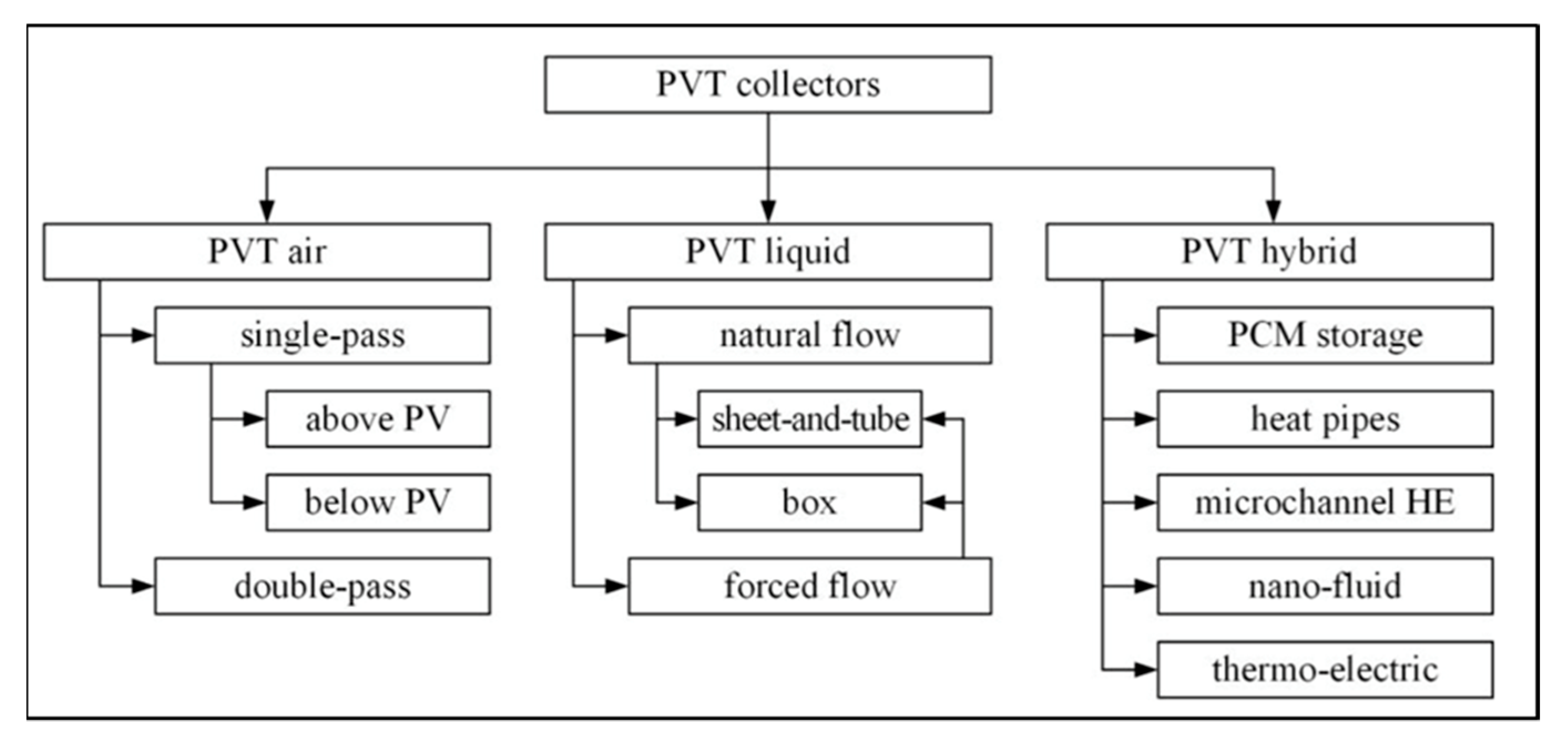
Figure 2.
Heat mat heat exchanger configuration [27].
Figure 2.
Heat mat heat exchanger configuration [27].

Figure 3.
Principle of a TRaNsient SYstem Simulation (TRNSYS) component subroutine.

Figure 4.
Flowchart of the model.

Figure 5.
Schematic of the system in TRNSYS platform.

Figure 6.
Comparison between mathematical and simulations models.

Figure 7.
Average temperature of the module without cooling.

Figure 8.
Average temperature of the module with cooling.

Figure 9.
Electrical output power of the module without cooling.

Figure 10.
Electrical output power of the module with cooling.
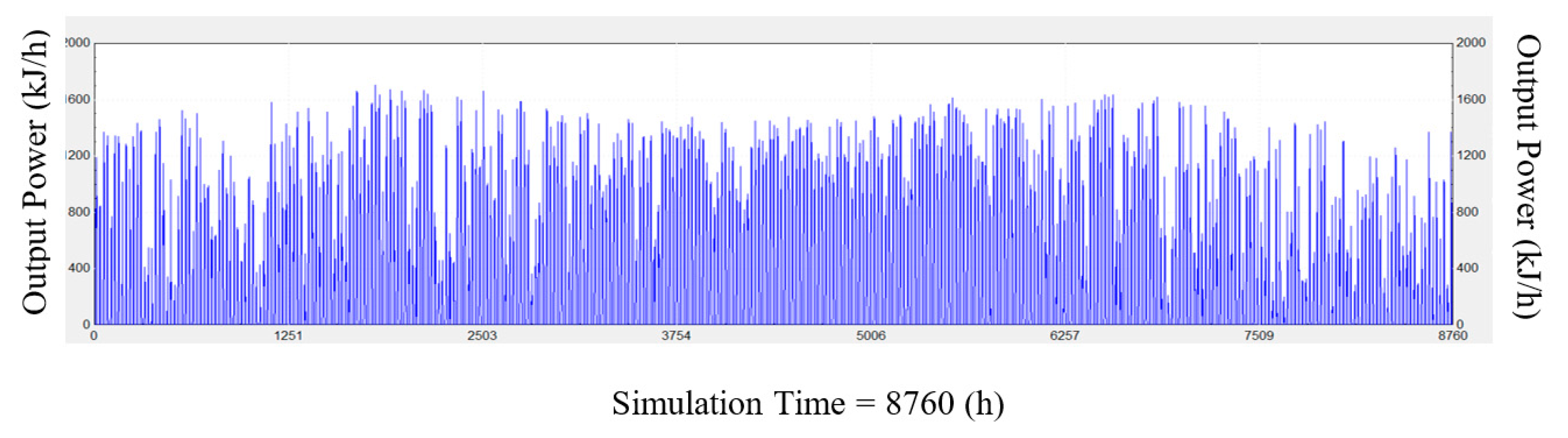
Figure 11.
Water temperature output and power to load.


Table 1.
Summary of PV cooling methods.
| Reference | Description | Method | Advantages | Disadvantages |
|---|---|---|---|---|
| Saikrishnan et al. [20] | Experimental Investigation of Solar Paraffin Wax Melting Unit Integrated with Phase Change Heat Energy Storage by Using Phase Change Material. | PCM was used as a type of heat storage material which was attached to the back of the PV panels. When the PV was subjected to solar radiation, the PCM material underwent a phase change from a solid to liquid condition, along with heat absorption. | Ability to store large amounts of energy in the daytime (during melting process) and releasing it at night. Increases the performance of the system around 5%, along with a rising electrical power production to 8%. | Low phase-change enthalpy, low thermal conductivity, and possible risk of flammability. Over time the material’s adsorptive capabilities degrade. The system cannot achieve the same performance during seasonal change, especially during winter and summer. |
| Mehrotra et al. [21] | Performance of a Solar Panel with the Water Immersion Cooling Technique. | Submerging the solar panel into the water to sustain their temperature, especially in peak solar radiation hours and hot climate. | Reduced PV module temperature. Effective increased efficiency when the accurate submersion depth is reached. | The nature of the technique used can affect the electrical efficiency after a period of time. |
| Irwan et al. [22] | Comparison of a Solar Panel Cooling System by Using a DC Brushless Fan and DC Water. | Used a DC brushless fan and water pump with an inlet and outlet manifold to obtain a steady movement of fresh air and circulation of water at both sides of the PV module. | Feasible technique which can increase the electrical output power significantly. The payback period of the investment can be reduced. | The technique consumes electricity and there can be a risk of break down Might require maintenance. |
| Borkar et al. [23] | Performance Evaluation of Photovoltaic Solar Panel Using Thermoelectric Cooling. | Thermoelectric cooling was used to increase the efficiency of the overall power output from the system by taking advantage of thermoelectric effect. | The technique used the waste heat from the panels to promote higher overall output efficiency. No direct contact with the PV module. | The development of the technology is slow and can be expensive. Low conversion efficiency rate was obtained. |
Table 2.
Components used for the system.
| Type | Name |
|---|---|
| 15 | Weather Data Processor |
| 50 | PV-Thermal Module |
| 4 | Storage Tank |
| 3 | Pump |
| 47 | Electrical Storage Battery |
| 48 | Inverter |
| 11 | Diverter/Tee Piece |
| 12 | Tempering Valve |
| 14 | Time Dependent Forcing Function (Load Profile) |
| 2 | Differential Controller |
| 46 | Integrator Printer |
| 65 | Online graphical plotter |
Table 3.
System parameters.
| Component | Descriptions | Value |
|---|---|---|
| PV/T Module | Module Area | 6.4 m2 |
| Fluid Specific Heat | 4.18 kJ/kg.K | |
| PV Reference Condition Efficiency | 15 % | |
| PV Cell Reference Temperature | 30 °C | |
| Solar Cell Efficiency Temperature Coefficient | 0.5%/K | |
| Packing Factor (ratio of PV cell area to absorber area) | 1 | |
| Inclination Angle | 36˚ | |
| Facing Orientation | South | |
| Pump | Maximum Flowrate | 60 kg/h |
| Maximum Power | 200 kJ/h (0.056 kW) | |
| Storage Tank | Tank Volume | 250 L |
| Maximum Heating Rate of Elements | 5000 kJ/h (1.39 kW) | |
| Battery Bank | Energy Capacity | 15 kWh |
© 2020 by the authors. Licensee MDPI, Basel, Switzerland. This article is an open access article distributed under the terms and conditions of the Creative Commons Attribution (CC BY) license (http://creativecommons.org/licenses/by/4.0/).
Share and Cite
MDPI and ACS Style
Khordehgah, N.; Żabnieńska-Góra, A.; Jouhara, H. Energy Performance Analysis of a PV/T System Coupled with Domestic Hot Water System. ChemEngineering 2020, 4, 22. https://doi.org/10.3390/chemengineering4020022
AMA Style
Khordehgah N, Żabnieńska-Góra A, Jouhara H. Energy Performance Analysis of a PV/T System Coupled with Domestic Hot Water System. ChemEngineering. 2020; 4(2):22. https://doi.org/10.3390/chemengineering4020022
Chicago/Turabian StyleKhordehgah, Navid, Alina Żabnieńska-Góra, and Hussam Jouhara. 2020. "Energy Performance Analysis of a PV/T System Coupled with Domestic Hot Water System" ChemEngineering 4, no. 2: 22. https://doi.org/10.3390/chemengineering4020022