Figure 1.
Illustration of the equipment used in Holter ECG clinical study, including: a commercial Holter ECG recorder (medilogAR 7L, Schiller AG, Switzerland) with a 7-wire patient cable [
37]; Recommended placement of 7 ECG electrodes on the human chest for 3-lead configuration (ECG1 from lead vector B (red) → A (green), ECG2 from lead vector D (yellow) → C (white), ECG3 from lead vector F (blue) → E (orange)); User interface of the commercial software for Holter data revision, showing the window for noise annotation with excluded noisy episodes (in grey).
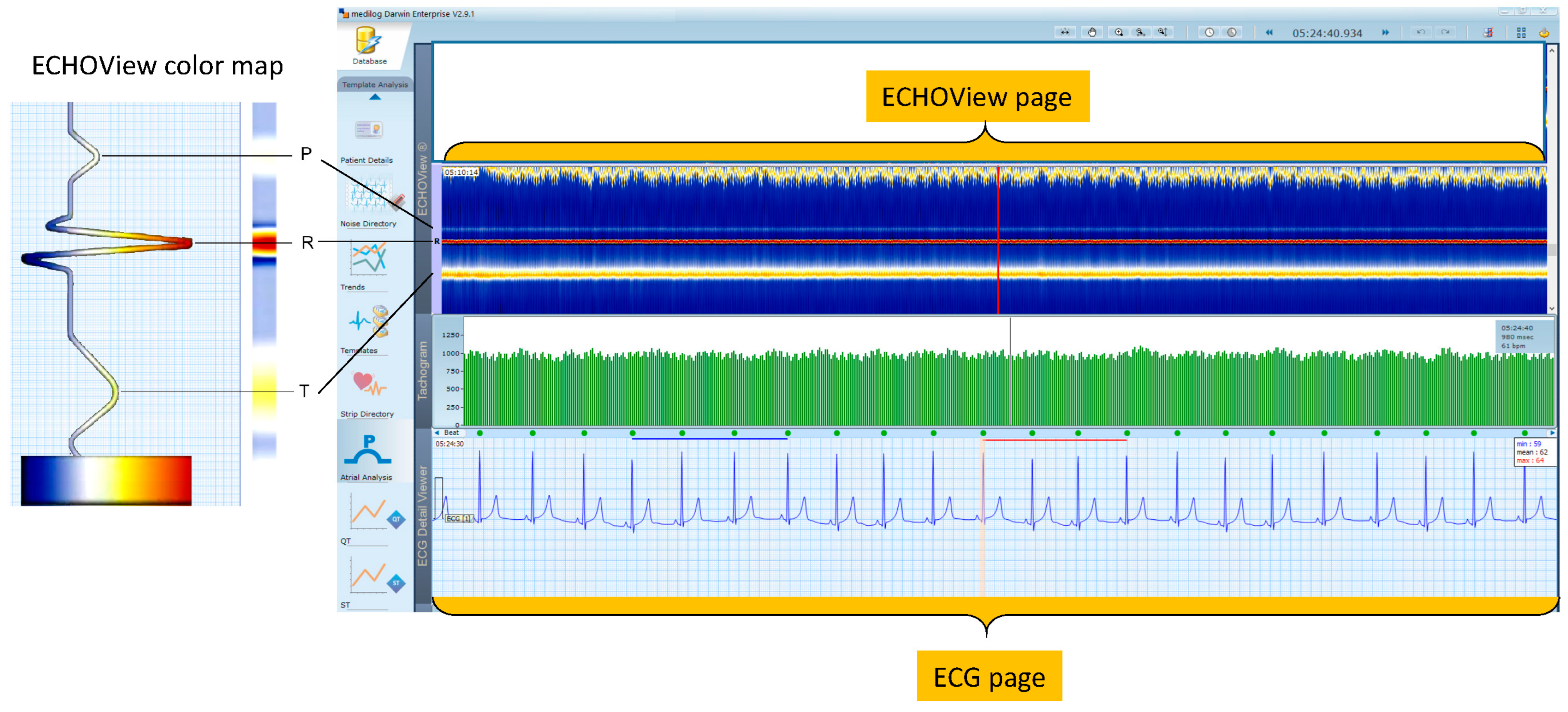
Figure 2.
(Left) Principle of ECHOView color map, flattening ECG beat waveform amplitude in a color-coded bar. (Right) DARWIN 2 user interface reviewing a Holter-ECG recording of a patient in normal sinus rhythm. One revision page includes the following traces: (top) One ECHOView page built by stacked color bars of about 1740 beats in a visible pattern R ± 750 ms; (middle) Tachogram of 600 RR-interval time series; (bottom) One ECG page, including 22 s ECG signal in standard time grid (25 mm/s). Vertical lines in the three traces (ECHOView, Tachogram, ECG) point to the same time in the Holter recording. They are guides for synchronized visualization of traces, which represent different number of beats and amounts of information. All traces and markers are part of the DARWIN 2 interface except both orange highlights of the ECG and ECHOView pages.
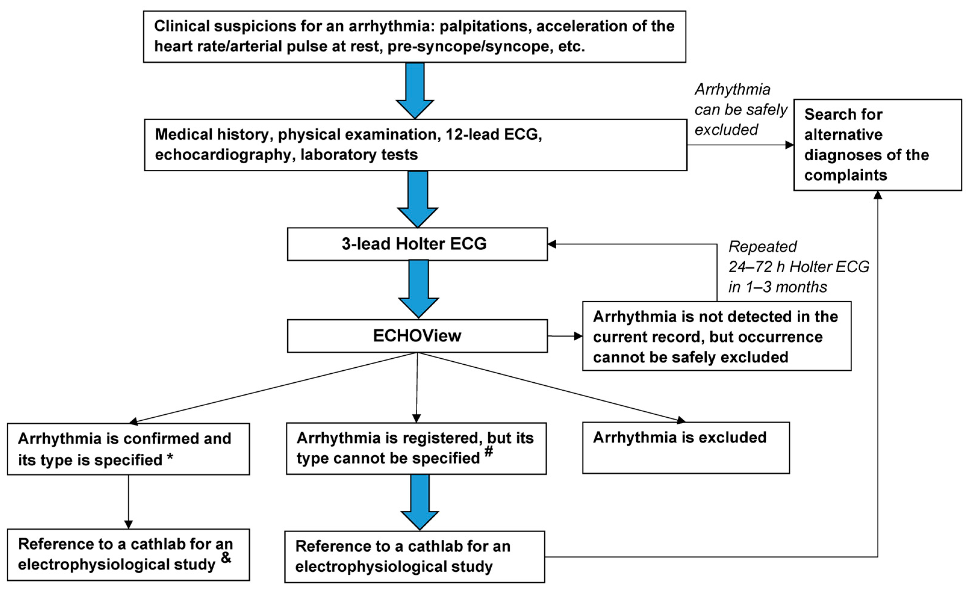
Figure 3.
Flowchart of the diagnostic approach applied to the patients in this study. The thick blue arrows indicate the obligatory diagnostic steps. Notes: * Diagnosis is based on the current ECS guidelines for the diagnosis of supraventricular and ventricular arrhythmias [
1].
# High-rate arrhythmias, artifacts, previous bundle branch block, poor contact of electrodes, loss of signal, or other factors that obscure ECG components, are essential for the diagnosis and specification of the type of arrhythmia.
& If arrhythmia episodes are causing hemodynamic instability or having a high symptomatic burden and are resistant/contraindicated for pharmacological treatment/patients unwilling to take antiarrhythmics.
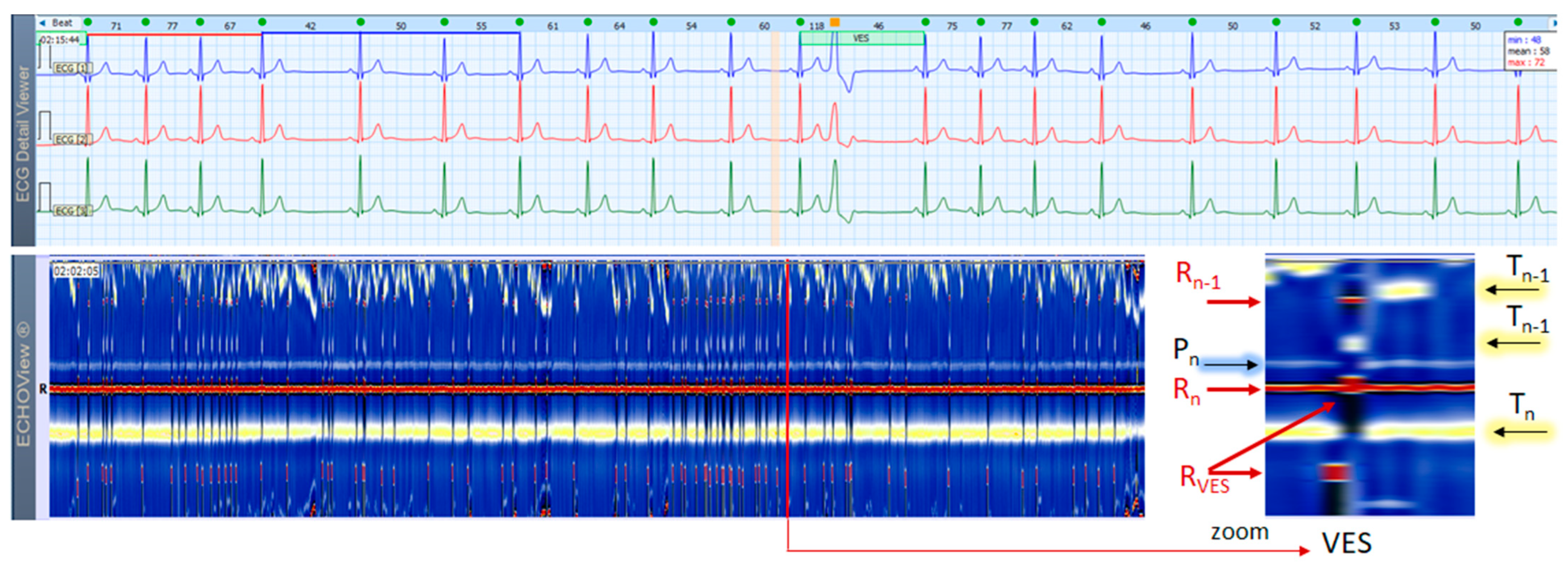
Figure 4.
A 3-lead Holter ECG strip (22 s, 25 mm/s) and ECHOView image (ECG lead 1, height = 1500 ms, width resolution = 80 beats/25 mm) of a patient with NSR and frequent early unifocal SVES. The two pages (ECG—top and ECHOView—bottom) are aligned with vertical lines. Zooming of the ECHOView area of interest around SVES shows that the early non-sinus ventricular depolarization (RSVES,) is visible as a red dot in the blue horizontal area between T-waves (Tn) and P-waves (Pn+1) of the sinus rhythm beats; the depolarization R-peak of the sinus beat preceding SVES (Rn−1) is visible as a red dot within the orange band of the sinus rhythm T-waves (Tn−1); the repolarization T-peak of the sinus beat preceding SVES (Tn−1) is visible as an orange dot within the blue horizontal area between Tn−1 and Pn of the sinus rhythm beats. SVES in the not zoomed ECHOView page are recognized as occasional narrow vertical lines with different colors than the background color map presented by the NSR. Pn, Pn+1—P-wave of the normal atrial depolarization (Pn: current, Pn+1: next); Rn—R-peak of ventricular depolarization; Rn−1—R-peak of previous normal ventricular depolarization; RSVES—R peak of SVES; Tn, Tn−1—T-wave of the normal ventricular repolarization (Tn: current, Tn−1: previous); NSR—normal sinus rhythm; SVES—supraventricular extrasystoles.
![Jcdd 10 00360 g004]()
Figure 5.
A 3-lead Holter ECG strip (22 s, 25 mm/s) and ECHOView image (ECG lead 1, height = 1500 ms, width resolution = 80 beats/25 mm) of a patient with NSR and frequent VES. The two pages (ECG—top and ECHOView—bottom) are aligned with vertical lines. Zoomed ECHOView around VES shows the early non-sinus ventricular depolarization (RVES) as a red band, which is thicker than (Rn) of normal sinus depolarization due to VES wide complex (consecutive not simultaneous excitation of both ventricles). The white-blue P-wave band (Pn) of NSR is interrupted during VES due to the lack of normal atrial excitation. The dark spot following RVES, spreading also on the yellow-white T-wave band (Tn) is due to ST-segment depression and a T-wave electric axis that is opposite to the electric axis of R-wave in VES. VES in the not zoomed ECHOView page are recognized as sporadic narrow vertical lines with a different color than the background color map presented by NSR. Pn—P-wave of the normal atrial depolarization; Rn—R-peak of ventricular depolarization; Rn−1—R-peak of previous normal ventricular depolarization; RVES—R peak of VES; Tn, Tn−1—T-wave of normal ventricular repolarization (Tn: current, Tn−1: previous); NSR—normal sinus rhythm; VES—ventricular extrasystoles.
![Jcdd 10 00360 g005]()
Figure 6.
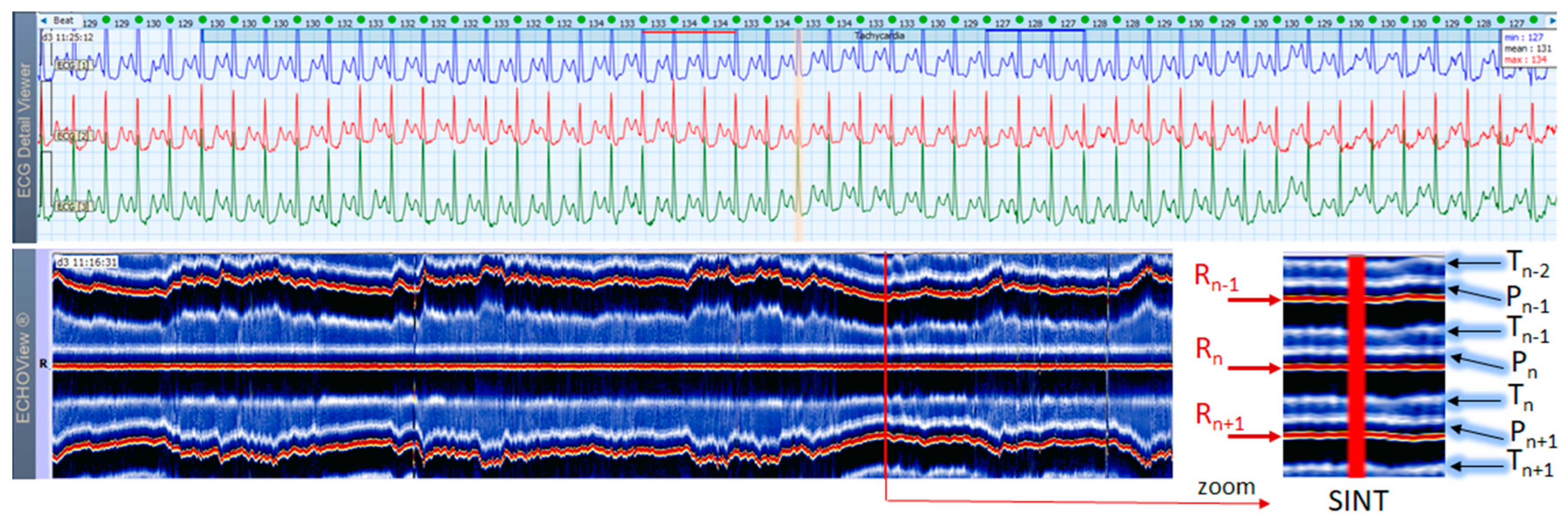
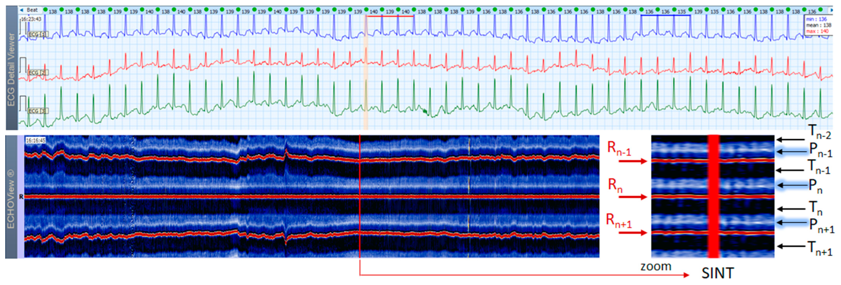
A 3-lead Holter ECG strip (22 s, 25 mm/s) and ECHOView image (ECG lead 1, height = 1500 ms, width resolution = 80 beats/25 mm) of a 46-year old female patient with SINT. The two pages (ECG—top and ECHOView—bottom) are aligned with vertical lines in the highest rate SINT (max HR = 134 bpm read from instant HR values above each QRS complex in the ECG page). In ECG, the high rate makes the P-wave to superimpose on the previous T-wave with no isoelectric line between them, so the ‘notch’ between T- an P-waves may be mistaken for a retrograde atrial excitation, found in AVRT with concealed accessory pathways and sometimes in AFL. Similar P-wave morphology may also be found in focal atrial tachycardia. In ECHOView (original and zoomed), the P-wave is a visible blue-white horizontal band (Pn), preceding the red R-wave line (Rn), which confirms the sinus rhythm. ECHOView color map: Blue-white traces (P-wave of atrial depolarization, Pn: current, Pn+1: next, Pn−1: previous); Red traces (R-peak of ventricular depolarization, Rn: current, Rn+1: next, Rn−1: previous); Blue-white traces (T-wave of ventricular repolarization, Tn: current, Tn+1: next, Tn−1, Tn−2: 2 previous). SINT—sinus tachycardia, AVRT—atrioventricular reentrant tachycardia, AFL—atrial flutter.
Figure 6.
A 3-lead Holter ECG strip (22 s, 25 mm/s) and ECHOView image (ECG lead 1, height = 1500 ms, width resolution = 80 beats/25 mm) of a 46-year old female patient with SINT. The two pages (ECG—top and ECHOView—bottom) are aligned with vertical lines in the highest rate SINT (max HR = 134 bpm read from instant HR values above each QRS complex in the ECG page). In ECG, the high rate makes the P-wave to superimpose on the previous T-wave with no isoelectric line between them, so the ‘notch’ between T- an P-waves may be mistaken for a retrograde atrial excitation, found in AVRT with concealed accessory pathways and sometimes in AFL. Similar P-wave morphology may also be found in focal atrial tachycardia. In ECHOView (original and zoomed), the P-wave is a visible blue-white horizontal band (Pn), preceding the red R-wave line (Rn), which confirms the sinus rhythm. ECHOView color map: Blue-white traces (P-wave of atrial depolarization, Pn: current, Pn+1: next, Pn−1: previous); Red traces (R-peak of ventricular depolarization, Rn: current, Rn+1: next, Rn−1: previous); Blue-white traces (T-wave of ventricular repolarization, Tn: current, Tn+1: next, Tn−1, Tn−2: 2 previous). SINT—sinus tachycardia, AVRT—atrioventricular reentrant tachycardia, AFL—atrial flutter.
![Jcdd 10 00360 g006]()
Figure 7.
A 3-lead Holter ECG strip (22 s, 25 mm/s) and ECHOView image (ECG lead 1, height = 1500 ms, width resolution = 80 beats/25 mm) of a 21-year old female patient with SINT. The two pages (ECG—top and ECHOView—bottom) are aligned with vertical lines in the highest rate SINT (max HR = 158 bpm read from instant HR values above each QRS complex in the ECG page). In ECG, the atypical morphology of the P-wave (narrow-based, tall, and sharp) and its superimposition on the previous T-wave requires differentiation from an atrial tachycardia. In ECHOView (original and zoomed), the P-wave is a visible blue-white horizontal band (Pn), preceding the red R-wave line (Rn), which confirms the sinus rhythm. ECHOView color map: Yellow-white trace (P-wave of the atrial depolarization, Pn: current, Pn+1, Pn+2: 2 next, Pn−1: previous); Red traces (R-peak of ventricular depolarization, Rn: current, Rn+1: next, Rn−1: previous); Blue-white traces (T-wave of ventricular repolarization, Tn: current, Tn+1: next, Tn−1, Tn−2: 2 previous). SINT—sinus tachycardia.
![Jcdd 10 00360 g007]()
Figure 8.
A 3-lead Holter ECG strip (22 s, 25 mm/s) and ECHOView image (ECG lead 1, height = 1500 ms, width resolution = 80 beats/25 mm) of a 38-year old male patient with SINT. The two pages (ECG—top and ECHOView—bottom) are aligned with vertical lines in the highest rate SINT (max HR = 148 bpm read from instant HR values above each QRS complex in the ECG page). In ECG, the atrial depolarization before the R wave is barely visible in the ECG channels and differentiation of SINT from AVNRT in this case is difficult. In ECHOView (original and zoomed), the P-wave is a visible white horizontal band (Pn), preceding the red R-wave line (Rn), which confirms the sinus rhythm. ECHOView color map: Blue-white traces (P-wave of atrial depolarization, Pn: current, Pn+1: next, Pn−1: previous); Red traces (R-peak of ventricular depolarization, Rn: current, Rn+1: next, Rn−1: previous); Black traces (T-wave of ventricular repolarization, Tn: current, Tn+1: next, Tn−1, Tn−2: 2 previous). SINT—sinus tachycardia, AVNRT—atrio-ventricular nodal reentrant tachycardia, AFL—atrial flutter.
![Jcdd 10 00360 g008]()
Figure 9.
A 3-lead Holter ECG strip (22 s, 25 mm/s) and ECHOView image (ECG lead 1, height = 1500 ms, width resolution = 80 beats/25 mm) of a 44-year old male patient presenting a short SVA episode, probably an accelerated nodal rhythm. The two pages (ECG—top and ECHOView—bottom) are aligned with vertical lines in the zone of interest, including SVA (HR = 91–99 bpm read from instant HR values above each QRS complex in the ECG page). In ECG, the P-wave is hidden inside the QRS complex or in the T-wave (best seen as a ‘notching’ of the T-wave of the last arrhythmia complex). In ECHOView, this arrhythmia is represented as a distinctive vertical line, clearly distinguishable from the adjacent sinus rhythm periods due to notable RR-interval change, leading to dislocation of red (Rn−1, Rn+1) and yellow (Tn−1) bands. The zoomed ECHOView shows important details, including a discontinuity of the P-wave band (Pn) for the time of the arrhythmia and slight changes in the T-wave band (Tn), probably due to superimposition with the atrial excitation. ECHOView color map: Blue-white trace (P-wave of atrial depolarization, Pn: current); Red traces (R-peak of ventricular depolarization, Rn: current, Rn+1: next, Rn−1: previous); Yellow-while traces (T-wave of ventricular repolarization, Tn: current, Tn−1: previous). SVA—supraventricular arrhythmia.
![Jcdd 10 00360 g009]()
Figure 10.
A 3-lead Holter ECG strip (22 s, 25 mm/s) and ECHOView image (ECG lead 1, height = 1500 ms, width resolution = 80 beats/25 mm) of a 62-year old female patient with PSVT (10 s). The two pages (ECG—top, ECHOView—bottom) are aligned with vertical lines in the zone of interest, including PSVT (HR = 118–167 bpm read from instant HR values above each QRS complex in the ECG page). In ECG, HR >100 bpm, changeable morphology of the atrial non-sinus P-wave (>3 different shapes) and varying RR intervals are consistent with a multifocal atrial tachycardia. AVRT or atypical AVNRT cannot be excluded either. In ECHOView, the PSVT run is marked by the appearance of two red R-wave bands of previous and next beats (Rn−1, Rn+1) due to RR-intervals shortening, as well as an interruption of the blue-white sinus P-wave band (Pn). The zoomed ECHOView clearly shows some important details in the dark-blue T-wave band (Tn), which is also interrupted by different-sized dark spots, representing the multifocal origination of atrial excitations, superimposing on the T-wave. ECHOView color map: Blue-white traces (P-wave of atrial depolarization, Pn: current, Pn+1: next); Red traces (R-peak of ventricular depolarization, Rn: current, Rn+1: next, Rn−1: previous); Dark-blue traces (T-wave of ventricular repolarization, Tn: current, Tn−1: previous, Tn+1: next). PSVT—paroxysmal supraventricular tachycardia, AVNRT—atrioventricular nodal reentrant tachycardia, AVRT—atrioventricular reentrant tachycardia.
![Jcdd 10 00360 g010]()
Figure 11.
A 3-lead Holter ECG strip (22 s, 25 mm/s) and ECHOView image (ECG lead 1, height = 1500 ms, width resolution = 80 beats/25 mm) of a 46-year old female patient with short PSVT episode (3 s). The two pages (ECG—top and ECHOView—bottom) are aligned with vertical lines in the zone of interest, including PSVT (HR = 112–138 bpm read from instant HR values above each QRS complex in the ECG page). In ECG, PSVT is seen as a 5-beat run of a multifocal tachycardia (≥3 different P-wave morphologies can be seen, the rhythm is irregular). Since all atrial non-sinus P-waves precede R-peak (Rn) and are very close to the timing of the normal sinus P-wave (Pn), the zoomed ECHOView shows that the P-wave band is not interrupted, but just displaced anteriorly to the adjacent sinus P-wave line. The arrhythmia episode itself is represented in ECHOView as a distinctive vertical line, well demarcated from sinus rhythm periods. ECHOView color map: Blue-white traces (P-wave of atrial depolarization, Pn: current, Pn−1: previous, Pn+1: next); Red traces (R-peak of ventricular depolarization, Rn: current, Rn+1: next, Rn−1: previous); Blue-white traces (T-wave of ventricular repolarization, Tn: current, Tn−1: previous). PSVT—paroxysmal supraventricular tachycardia.
![Jcdd 10 00360 g011]()
Figure 12.
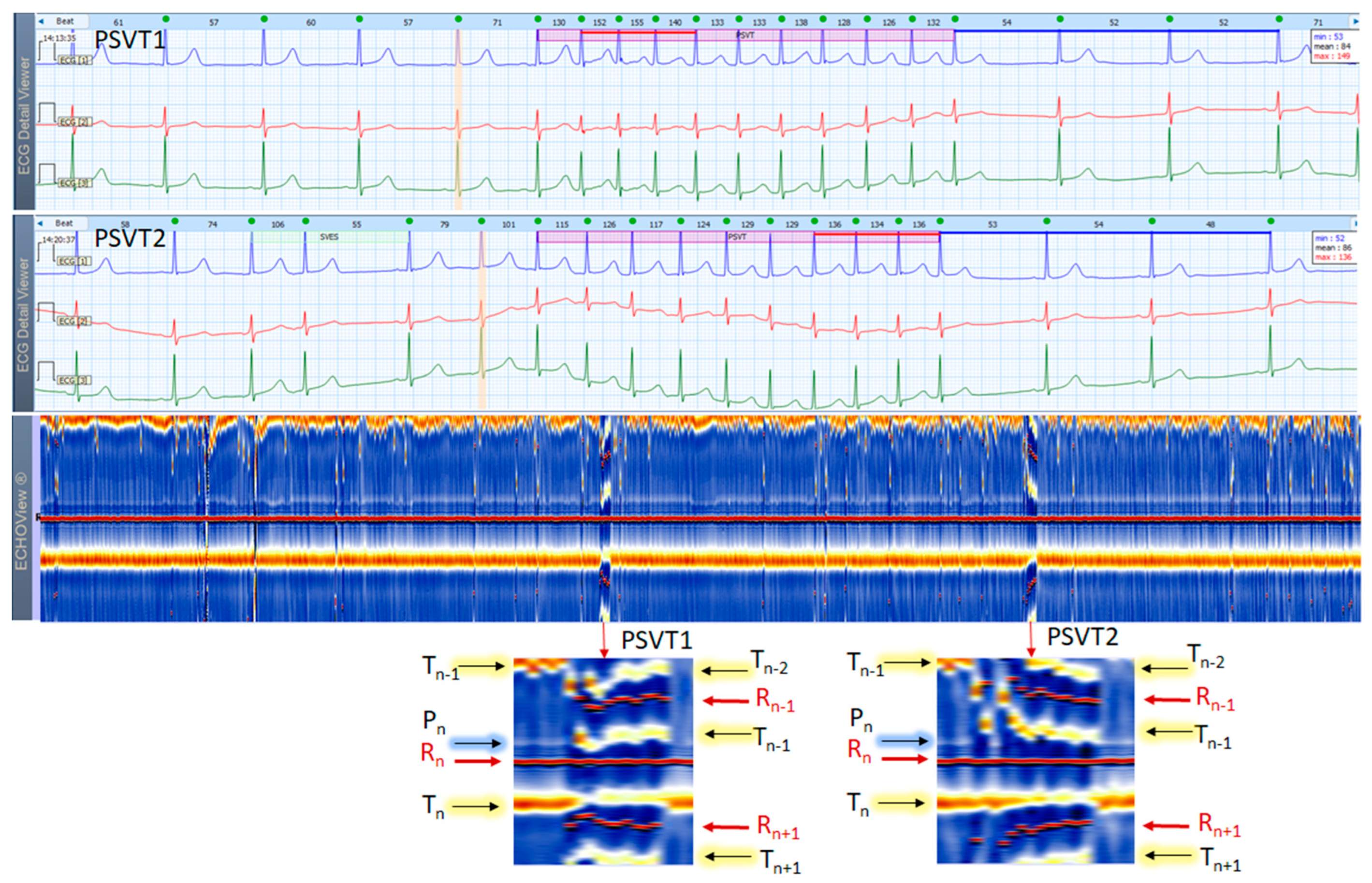
Two 3-lead Holter ECG strips (22 s, 25 mm/s) and corresponding ECHOView image (ECG lead 1, height = 1500 ms, width resolution = 80 beats/25 mm) of a 37-year old female patient with frequent SVES and two short PSVT episodes (4.2 s): PSVT1 (HR = 126–155 bpm) and PSVT2 (HR = 115–136 bpm, read from instant HR values above each QRS complex in the ECG page). In ECG, at first glance the SVT looks similar to an AVNRT (a paroxysmal, narrow-QRS complex tachycardia, starting after an SVES, HR looks regular, and no atrial P-waves are visible). A closer look, however, may identify a subtle ‘notching’ on the top of the T-wave in lead 2 of PSVT1 strip. If we accept it as a retrograde P-wave with an RP interval >90 ms, then an AVRT must be excluded (a concealed accessory pathway with retrograde conduction). A focal AT is also possible. In zoomed ECHOView, the P-wave band during PSVT is interrupted and the P-wave segment (Pn) is embedded in the T-wave (Tn−1), which supports the necessity to exclude an AVRT with a concealed retrograde pathway. In a typical ‘slow-fast’ AVNRT, P-waves are hidden in the QRS complex, and in a ‘fast-slow’ AVNRT, P-waves are visible between the QRS and T-wave (ST-segment). In these cases, the P-wave segment is expected to be found within or very close to the R-wave band in EchoView, which is not seen in this patient. ECHOView color map: Blue-white trace (P-wave of atrial depolarization, Pn: current); Red traces (R-peak of ventricular depolarization, Rn: current, Rn+1: next, Rn−1: previous); Orange-white traces (T-wave of ventricular repolarization, Tn: current, Tn−1: previous, Tn+1: next). PSVT—paroxysmal supraventricular tachycardia, SVES—supraventricular extrasystole, AVNRT—atrioventricular nodal reentrant tachycardia; AVRT—atrio-ventricular reentrant tachycardia, AT—atrial tachycardia.
Figure 12.
Two 3-lead Holter ECG strips (22 s, 25 mm/s) and corresponding ECHOView image (ECG lead 1, height = 1500 ms, width resolution = 80 beats/25 mm) of a 37-year old female patient with frequent SVES and two short PSVT episodes (4.2 s): PSVT1 (HR = 126–155 bpm) and PSVT2 (HR = 115–136 bpm, read from instant HR values above each QRS complex in the ECG page). In ECG, at first glance the SVT looks similar to an AVNRT (a paroxysmal, narrow-QRS complex tachycardia, starting after an SVES, HR looks regular, and no atrial P-waves are visible). A closer look, however, may identify a subtle ‘notching’ on the top of the T-wave in lead 2 of PSVT1 strip. If we accept it as a retrograde P-wave with an RP interval >90 ms, then an AVRT must be excluded (a concealed accessory pathway with retrograde conduction). A focal AT is also possible. In zoomed ECHOView, the P-wave band during PSVT is interrupted and the P-wave segment (Pn) is embedded in the T-wave (Tn−1), which supports the necessity to exclude an AVRT with a concealed retrograde pathway. In a typical ‘slow-fast’ AVNRT, P-waves are hidden in the QRS complex, and in a ‘fast-slow’ AVNRT, P-waves are visible between the QRS and T-wave (ST-segment). In these cases, the P-wave segment is expected to be found within or very close to the R-wave band in EchoView, which is not seen in this patient. ECHOView color map: Blue-white trace (P-wave of atrial depolarization, Pn: current); Red traces (R-peak of ventricular depolarization, Rn: current, Rn+1: next, Rn−1: previous); Orange-white traces (T-wave of ventricular repolarization, Tn: current, Tn−1: previous, Tn+1: next). PSVT—paroxysmal supraventricular tachycardia, SVES—supraventricular extrasystole, AVNRT—atrioventricular nodal reentrant tachycardia; AVRT—atrio-ventricular reentrant tachycardia, AT—atrial tachycardia.
![Jcdd 10 00360 g012]()
Figure 13.
A 3-lead Holter ECG strip (22 s, 25 mm/s) and ECHOView image (ECG lead 1, height = 1500 ms, width resolution = 80 beats/25 mm) of a 68-year old male patient with persistent AF. The two pages (ECG—top and ECHOView—bottom) are aligned with vertical lines. In ECG, the typical AF rhythm irregularity is visible (min–max HR = 60–103 bpm read from instant HR values above each QRS complex in the ECG page). However, the atrial f-waves are not readily visible due to a notable isoelectric line drift possibly in conditions of patient movements. In ECHOView, no distinctive blue-white band typical for the sinus-rhythm P-waves or atrial excitations in SVTs can be seen above the red R-wave line (Rn), which confirms AF. Instead, the blue-white band of ventricular repolarization (Tn) following the R-wave can be seen below the red line (Rn). Due to AF rhythm irregularity, the T-waves of the previous beats (Tn−1) appear at irregular intervals before R-waves (Rn), which are seen as scattered blue-white lines above the red line (Rn). ECHOView color map: Red traces (R-peak of ventricular depolarization, Rn: current, Rn+1: next, Rn−1: previous); Blue-white traces (T-wave of ventricular repolarization, Tn: current, Tn+1: next, Tn−1: previous). AF—atrial fibrillation.
![Jcdd 10 00360 g013]()
Figure 14.
A 3-lead Holter ECG strip (22 s, 25 mm/s) and ECHOView image (ECG lead 1, height = 1500 ms, width resolution = 80 beats/25 mm) of a 84-year old male patient with recurrent persistent AF. The two pages (ECG—top and ECHOView—bottom) are aligned with vertical lines. In ECG, the typical AF rhythm irregularity is visible (min–max HR = 46–150 bpm read from instant HR values above each QRS complex in the ECG page). The fibrillation ‘f’ waves are larger than usual—this type of AF is often regarded as ‘gross AF’. In such patients, differentiation of AF from AFL with variable atrioventricular conduction or from multifocal AT might not be so easy, which could affect the therapeutic decision about restoration and maintenance of sinus rhythm. In ECHOView, no distinctive blue-white band typical for the sinus-rhythm P-waves or atrial excitations in SVTs can be seen above the red R-wave line (Rn). Instead, randomly distributed white dots (above and below Rn line) are noted to probably depict the ‘f’ waves. Due to AF rhythm irregularity, the R-peaks of previous and next beats (Rn−1, Rn+1) appear at irregular intervals, which are well seen as scattered red dots above and below the red line of the central R-wave (Rn). This is the typical ECHOView pattern, which confirms AF. The two wide QRS complexes are probably supraventricular excitations (part of AF) with a functional BBB due to the so-called ‘Ashmann’ phenomenon (aberrant ventricular conduction due to a change in QRS cycle length). ECHOView color map: Red trace and dots (R-peak of ventricular depolarization, Rn: current, Rn+1: next, Rn−1: previous); Blue-white trace (T-wave of ventricular repolarization, Tn: current); random blue-white dots (atrial fibrillatory f-waves). AF—atrial fibrillation, AFL—atrial flutter, SVT—supraventricular tachycardia, AT—atrial tachycardia, BBB—Bundle Branch Block.
![Jcdd 10 00360 g014]()
Figure 15.
A 3-lead Holter ECG strip (22 s, 25 mm/s) and ECHOView image (ECG lead 1, height = 1500 ms, width resolution = 80 beats/25 mm) of a 61-year old male patient with AFL with atrial-ventricular conduction 2:1. The two pages (ECG—top and ECHOView—bottom) are aligned with vertical lines in high-rate AFL (min–max HR = 138–146 bpm read from instant HR values above each QRS complex in the ECG page). In ECG, the deflections of the isoelectric line (‘F’ waves) are not as typically described (‘saw-like’)—a focal/multifocal AT may have similar appearance. The ECHOView map shows rapid and regular HR typical for AFL, seen as stable red bands of previous (Rn−1) and next beats (Rn+1). Cardiac repolarization is recognized as a blue-white band, which follows sequential R-peak at a queasy-equal delay (Tn: is the band of the current beat, Tn−1 is the band of the previous beat). The F-waves of the macro-reentrant excitations of the atria can be seen as two blue-white bands equally spaced between any two adjacent R-peaks. The long-term ECHOView map shows certain changes in the F-wave conduction, where the first F-wave and T-wave are overlapping (most left part) but further diverge and form separate blue-white traces (most right part). This pattern is quite different than the single P-wave band in SINT and AT, or randomly distributed f-wave white dots in AF. ECHOView color map: Blue-white traces (F-waves of atrial depolarization, T-wave of ventricular repolarization, Tn: current, Tn−1: previous), Red traces (R-peak of ventricular depolarization, Rn: current, Rn+1: next, Rn−1: previous). AFL—atrial flutter, AF—atrial fibrillation, SINT—sinus tachycardia, AT—atrial tachycardia.
![Jcdd 10 00360 g015]()
Figure 16.
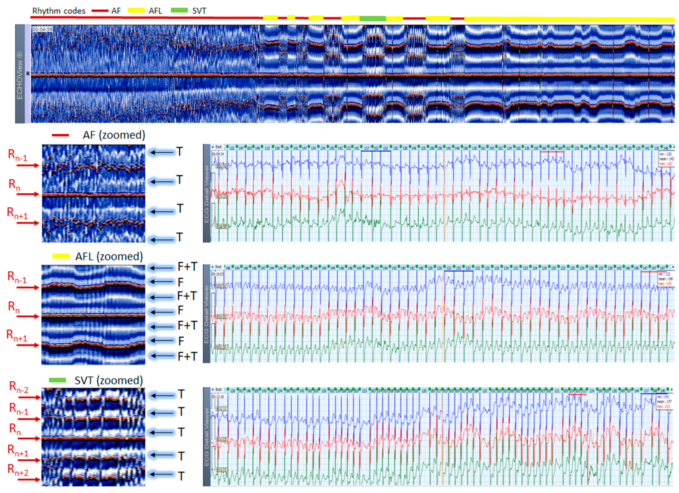
ECHOView image (ECG lead 1, height = 1500 ms, width resolution = 80 beats/25 mm) of a 61-year old male patient with alternating arrhythmia episodes, the period of which is marked at the top of the image by a horizontal bar with rhythm color codes: red (AF), yellow (AFL), green (SVT). Zoomed ECHOView images of selected arrhythmia episodes and their corresponding 3-lead Holter ECG strips (22 s, 25 mm/s) are presented: top—AF, min–max HR = 117–163 bpm; middle—AFL with atrial-ventricular conduction 2:1, min–max HR = 132–147 bpm; bottom—SVT with a characteristic of high-rate multifocal AT, min–max HR = 117–224 bpm. The three arrhythmias have the typical pattern observed in ECHOView for AF (absence of P-wave band and scattered red dots of R-wave peaks), AFL (presence of two blue-white F-wave bands and stable red bands of R-wave peaks), SVT (presence of one blue-white band of ventricular repolarization (suggested superposition with multifocal atrial excitation) and stable red bands of R-wave peaks). In this case, ECHOView is very important for differentiation between the second and third arrhythmia, because at first glance ECG strips seem similar. ECHOView color map: Blue-white traces (F-waves of atrial flutter, F + T: F-waves superimposed with ventricular repolarization); Red traces (R-peak of ventricular depolarization, Rn: current, Rn+1, Rn+2: 2 next, Rn−1, Rn−2: 2 previous); Blue-white traces (T-wave of ventricular repolarization). AF—atrial fibrillation, AFL—atrial flutter, AT—atrial tachycardia, SVT—supraventricular tachycardia.
Figure 16.
ECHOView image (ECG lead 1, height = 1500 ms, width resolution = 80 beats/25 mm) of a 61-year old male patient with alternating arrhythmia episodes, the period of which is marked at the top of the image by a horizontal bar with rhythm color codes: red (AF), yellow (AFL), green (SVT). Zoomed ECHOView images of selected arrhythmia episodes and their corresponding 3-lead Holter ECG strips (22 s, 25 mm/s) are presented: top—AF, min–max HR = 117–163 bpm; middle—AFL with atrial-ventricular conduction 2:1, min–max HR = 132–147 bpm; bottom—SVT with a characteristic of high-rate multifocal AT, min–max HR = 117–224 bpm. The three arrhythmias have the typical pattern observed in ECHOView for AF (absence of P-wave band and scattered red dots of R-wave peaks), AFL (presence of two blue-white F-wave bands and stable red bands of R-wave peaks), SVT (presence of one blue-white band of ventricular repolarization (suggested superposition with multifocal atrial excitation) and stable red bands of R-wave peaks). In this case, ECHOView is very important for differentiation between the second and third arrhythmia, because at first glance ECG strips seem similar. ECHOView color map: Blue-white traces (F-waves of atrial flutter, F + T: F-waves superimposed with ventricular repolarization); Red traces (R-peak of ventricular depolarization, Rn: current, Rn+1, Rn+2: 2 next, Rn−1, Rn−2: 2 previous); Blue-white traces (T-wave of ventricular repolarization). AF—atrial fibrillation, AFL—atrial flutter, AT—atrial tachycardia, SVT—supraventricular tachycardia.
![Jcdd 10 00360 g016]()
Figure 17.
A 3-lead Holter ECG strip (22 s, 25 mm/s) and ECHOView image (ECG lead 1, height = 1500 ms, width resolution = 80 beats/25 mm) of 44-year old male patient with NSR and a short NSVT episode (4 s). The two pages (ECG—top and ECHOView—bottom) are aligned with vertical lines in the zone of interest including NSVT (min–max HR = 153–183 bpm read from instant HR values above each QRS complex in the ECG page). Both, ECG and ECHOView present distinctive NSVT pattern morphology compared to NSR. During NSVT, the ECHOView image shows: (i) interruption of the blue-white P-wave band (Pn) of NSR due to the lack of normal atrial excitation; (ii) interruption of the orange-white T-wave band (Tn) of NSR due to ST-segment depression and an inversion of the T-wave electric axis; (iii) appearance of four red R-wave bands of previous and next beats (Rn−2, Rn−1, Rn+1, Rn+2) due to RR-intervals shortening; (iv) widening of the central R-wave band due to QRS complex enlargement. The NSVT image appears as horizontal red and black bands, corresponding to strongly positive R-peaks and strongly negative T-waves. During NSR, the occasional vertical line disruptions of the ECHOView map correspond to single VES similar to ones in the NSVT rhythm. ECHOView color map: Blue-white traces (P-wave of atrial depolarization, Pn: current); Red traces (R-peak of ventricular depolarization, Rn: current, Rn+2, Rn+1: 2 next, Rn−1, Rn−2: 2 previous); Orange-white traces (T-wave of ventricular repolarization, Tn: current, Tn−1: previous). NSVT—non-sustained ventricular tachycardia, NSR—normal sinus rhythm, VES—ventricular extrasystole.
![Jcdd 10 00360 g017]()


