
A Note on the Drag Coefficient of Steady Flow of Non-Newtonian, Power-Law Fluids across Unbounded Two-Dimensional Bodies at Low Reynolds Numbers

Abstract
:1. Introduction
2. The Mathematical Model and Numerical Code
3. Results and Discussion
4. Conclusions
Conflicts of Interest
References
- Zdravkovich, M.M. Flow around Circular Cylinders; Oxford University Press: Oxford, UK, 1997. [Google Scholar]
- Denier, J.P.; Dabrowski, P.P. On the boundary-layer equations for power-law fluids. Proc. R. Soc. Lond. A 2004, 460, 3143–3158. [Google Scholar] [CrossRef]
- Lee, Y.S.; Wetzel, E.D.; Wagner, N.J. The ballistic impact characteristics of Kevlar® woven fabrics impregnated with a colloidal shear thickening fluid. J. Mater. Sci. 2003, 38, 2825–2833. [Google Scholar] [CrossRef]
- Pantokratoras, A. Further results on non-Newtonian power-law flows past a two-dimensional flat plate with finite length. J. Mech. Sci. Technol. 2013, 27, 1995–2003. [Google Scholar] [CrossRef]
- Pantokratoras, A. Steady flow of a power-law non-Newtonian fluid across an unconfined square cylinder. J. Appl. Mech. Tech. Phys. 2016, 57, 264–274. [Google Scholar] [CrossRef]
- Oseen, C.W. Neuere Methoden und Ergebnisse in der Hydrodynamik; Leipzig Akademische Verlagsgesellschaft M.B.H: Leipzig, Germany, 1927; pp. 162–163. [Google Scholar]
- Tanner, R.I. Stokes paradox for power-law fluids around a cylinder. J. Non-Newtonian Fluid Mech. 1993, 50, 217–224. [Google Scholar] [CrossRef]
- Whitney, M.J.; Rodin, G.J. Force-velocity relationships for rigid bodies translating through unbounded shear-thinning power-law fluids. Int. J. Non-Linear Mech. 2001, 36, 947–953. [Google Scholar] [CrossRef]
- Marusic-Paloka, E. On the Stokes paradox for power-law fluids. Z. Angew. Math. Mech. 2001, 81, 31–36. [Google Scholar] [CrossRef]


| n | Circular Cylinder Present Work | Square Cylinder [5] | Normal Flat Plate [4] | ||||||
|---|---|---|---|---|---|---|---|---|---|
| Re | 0.001 | 0.01 | 0.1 | 0.001 | 0.01 | 0.1 | 0.001 | 0.01 | 0.1 |
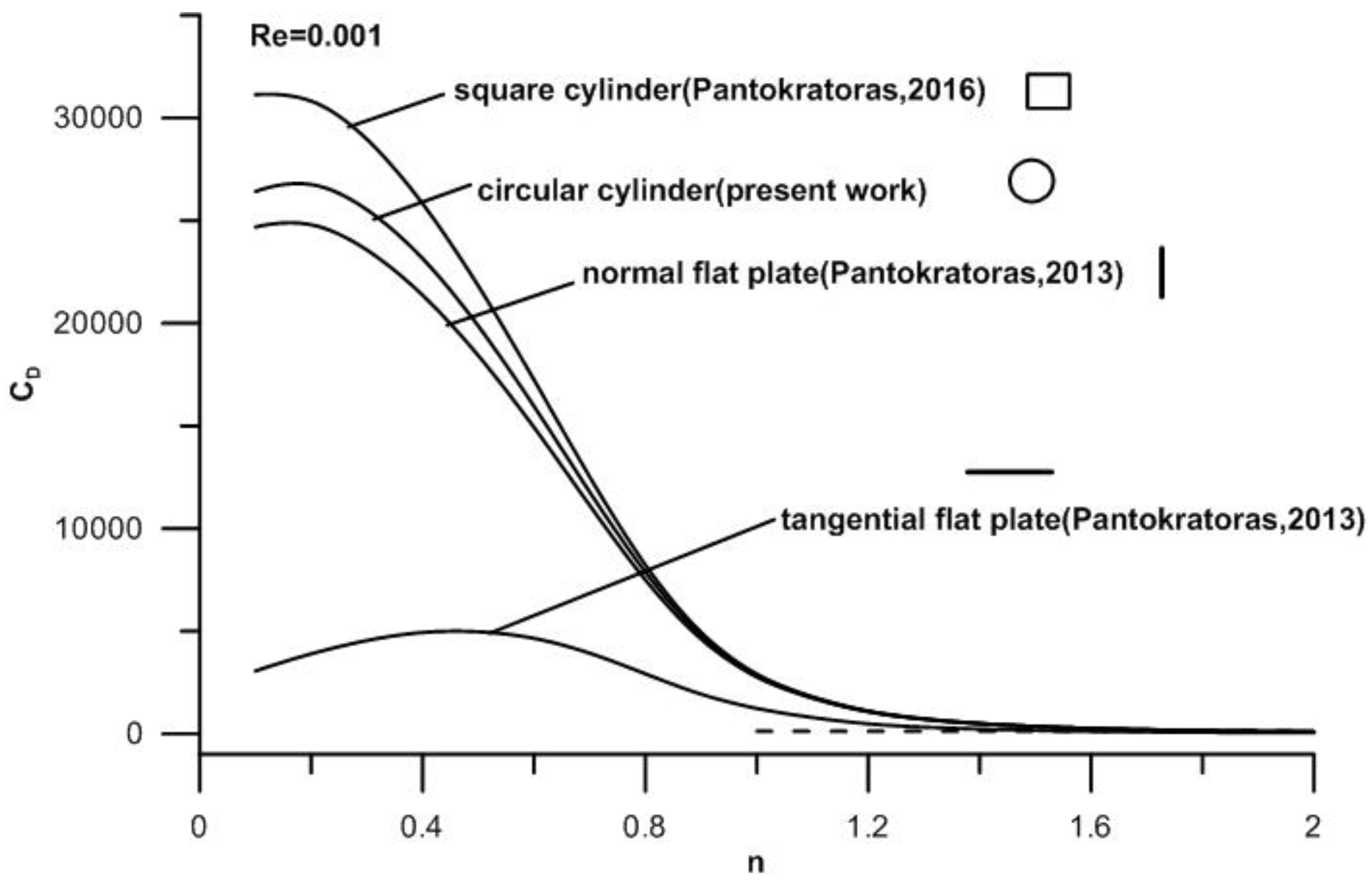
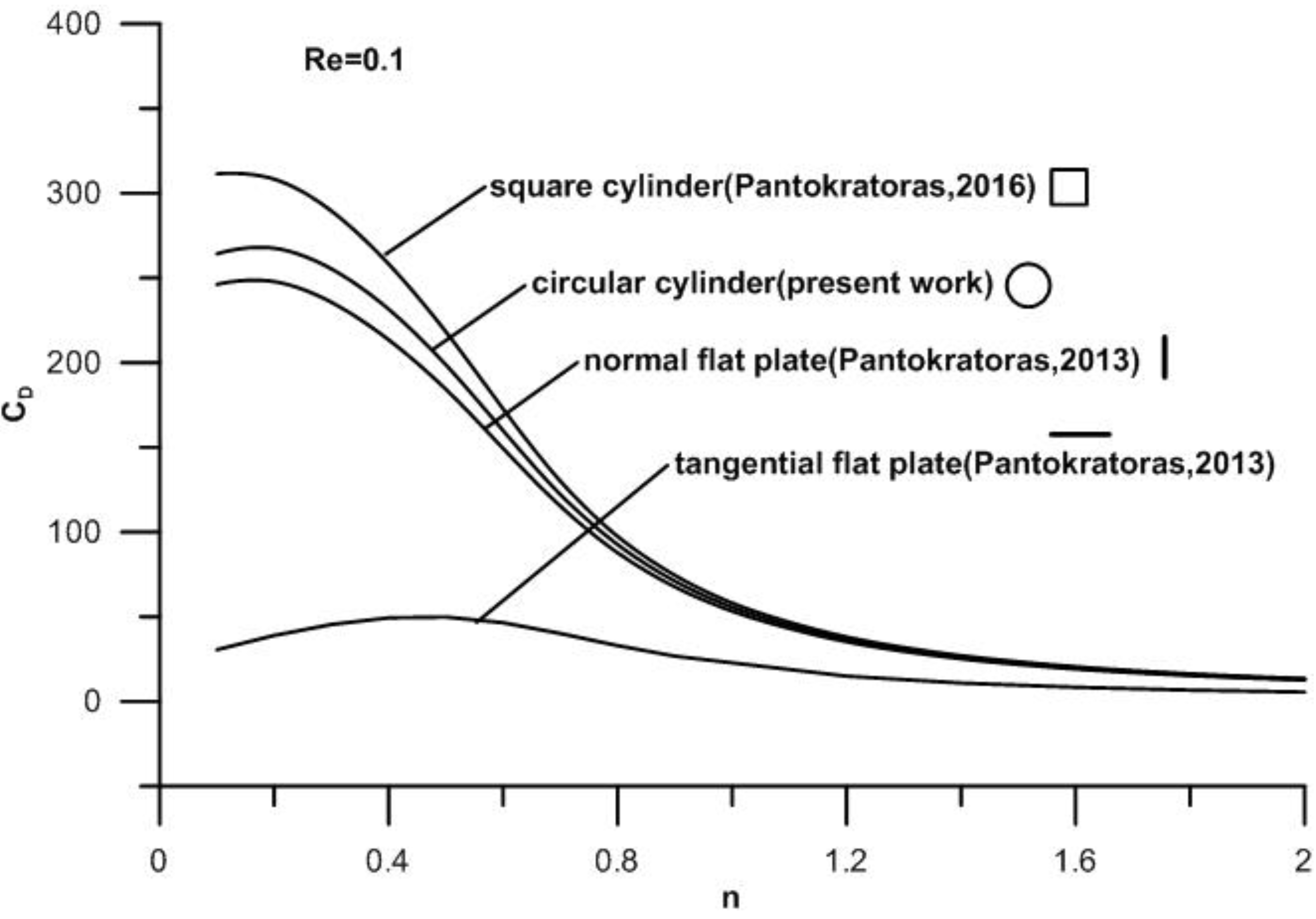
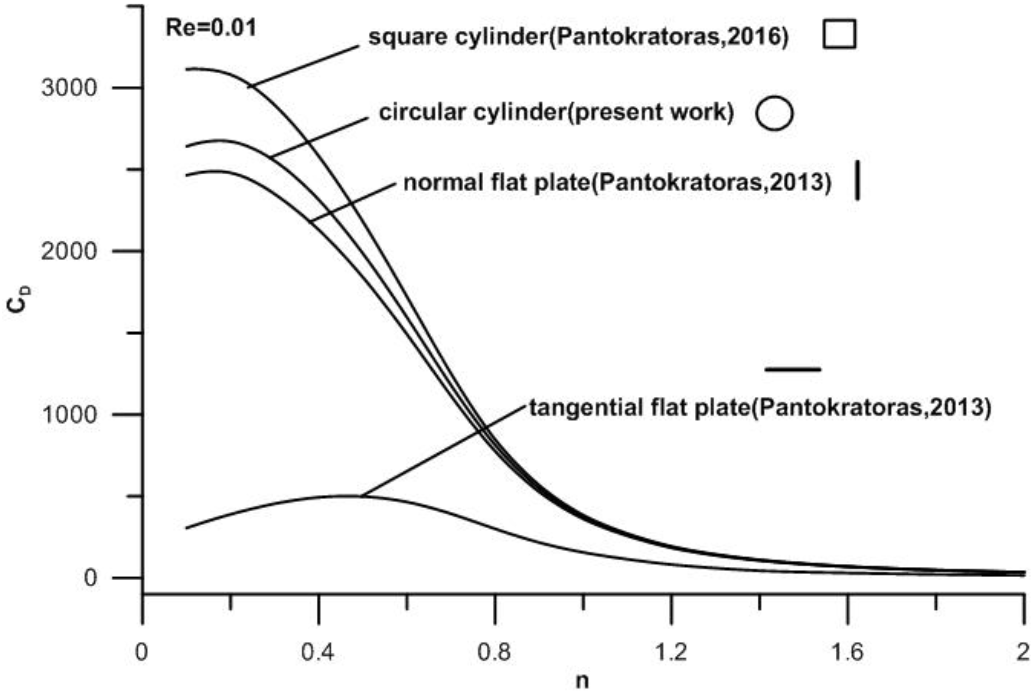
| 0.1 | 26,421 | 2642 | 264.23 | 31,134 | 3114 | 311.46 | 24,686 | 2465.0 | 246.20 |
| 0.2 | 26,764 | 2672 | 267.56 | 30,824 | 3081 | 308.31 | 24,802 | 2480.0 | 247.84 |
| 0.3 | 25,534 | 2553 | 255.35 | 28,961 | 2895 | 289.53 | 23,570 | 2350.0 | 235.66 |
| 0.4 | 23,155 | 2315 | 231.57 | 25,827 | 2582 | 258.22 | 21,369 | 2131.0 | 213.49 |
| 0.5 | 19,866 | 1986.6 | 198.70 | 21,817 | 2181.7 | 218.22 | 18,425 | 1841.0 | 184.27 |
| 0.6 | 15,956 | 1595.5 | 159.92 | 17,243 | 1722.0 | 172.69 | 14,930 | 1492.0 | 149.35 |
| 0.7 | 11,779 | 1180.0 | 122.17 | 12,517 | 1251.3 | 130.07 | 11,130 | 1115.0 | 115.32 |
| 0.8 | 7879 | 814.13 | 92.636 | 8227 | 848.14 | 97.449 | 7500.9 | 776.54 | 87.800 |
| 0.9 | 4797 | 548.03 | 71.054 | 4946 | 567.83 | 74.487 | 4617.7 | 527.33 | 67.700 |
| 1.0 | 2846 | 373.67 | 55.711 | 2912 | 384.80 | 58.143 | 2769.5 | 362.03 | 53.341 |
| 1.2 | 1097 | 189.79 | 36.678 | 1113 | 194.24 | 38.100 | 1077.6 | 184.96 | 35.282 |
| 1.4 | 501.2 | 109.22 | 26.147 | 507.3 | 111.53 | 27.098 | 494.12 | 106.84 | 25.230 |
| 1.6 | 266.3 | 69.826 | 19.855 | 269.3 | 71.232 | 20.554 | 262.99 | 68.421 | 19.205 |
| 1.8 | 159.2 | 48.439 | 15.829 | 161.0 | 49.415 | 16.382 | 157.41 | 47.505 | 15.343 |
| 2.0 | 104.2 | 35.785 | 13.106 | 105.4 | 36.524 | 13.565 | 103.06 | 35.127 | 12.734 |
| 1.0 | 2846 | 373.67 | 55.711 | ||||||
| Oseen | 2821 | 380.37 | 58.383 | ||||||
| Difference % | 0.9 | 1.8 | 4.8 | ||||||
| n | A |
|---|---|
| 0.1 | 26.42 |
| 0.2 | 26.72 |
| 0.3 | 25.53 |
| 0.4 | 23.16 |
| 0.5 | 19.90 |
© 2017 by the author; licensee MDPI, Basel, Switzerland. This article is an open access article distributed under the terms and conditions of the Creative Commons Attribution (CC BY) license ( http://creativecommons.org/licenses/by/4.0/).
Share and Cite
Pantokratoras, A. A Note on the Drag Coefficient of Steady Flow of Non-Newtonian, Power-Law Fluids across Unbounded Two-Dimensional Bodies at Low Reynolds Numbers. Fluids 2017, 2, 5. https://doi.org/10.3390/fluids2010005
Pantokratoras A. A Note on the Drag Coefficient of Steady Flow of Non-Newtonian, Power-Law Fluids across Unbounded Two-Dimensional Bodies at Low Reynolds Numbers. Fluids. 2017; 2(1):5. https://doi.org/10.3390/fluids2010005
Chicago/Turabian StylePantokratoras, Asterios. 2017. "A Note on the Drag Coefficient of Steady Flow of Non-Newtonian, Power-Law Fluids across Unbounded Two-Dimensional Bodies at Low Reynolds Numbers" Fluids 2, no. 1: 5. https://doi.org/10.3390/fluids2010005
APA StylePantokratoras, A. (2017). A Note on the Drag Coefficient of Steady Flow of Non-Newtonian, Power-Law Fluids across Unbounded Two-Dimensional Bodies at Low Reynolds Numbers. Fluids, 2(1), 5. https://doi.org/10.3390/fluids2010005