Experimental Measurement of Dolphin Thrust Generated during a Tail Stand Using DPIV

 ,
,
Abstract
:1. Introduction
2. Materials and Methods
2.1. Experimental Animals and Microbubbles
2.2. Bubble DPIV
2.3. Thrust Calculations
2.4. Statistical Analysis
3. Results
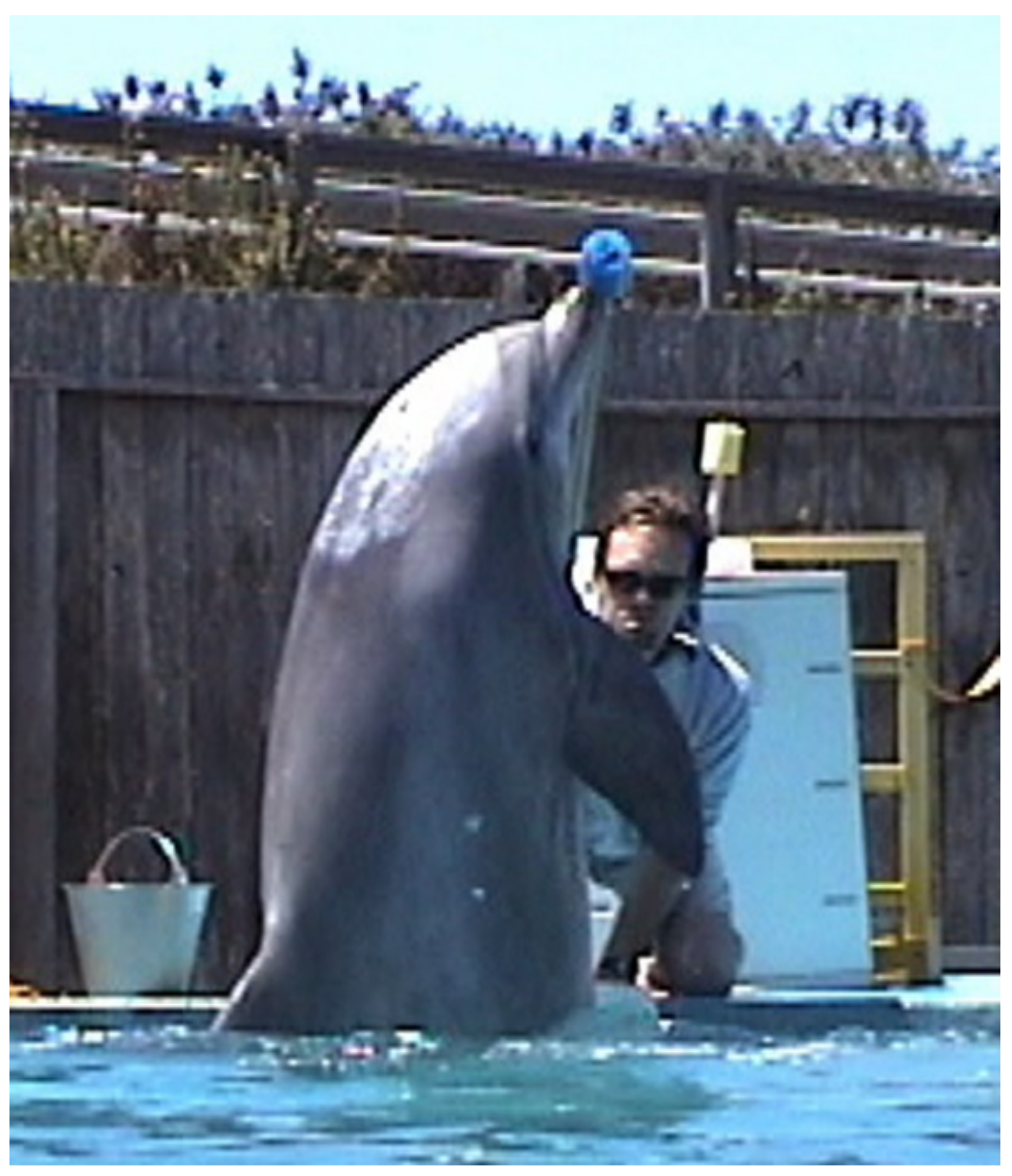
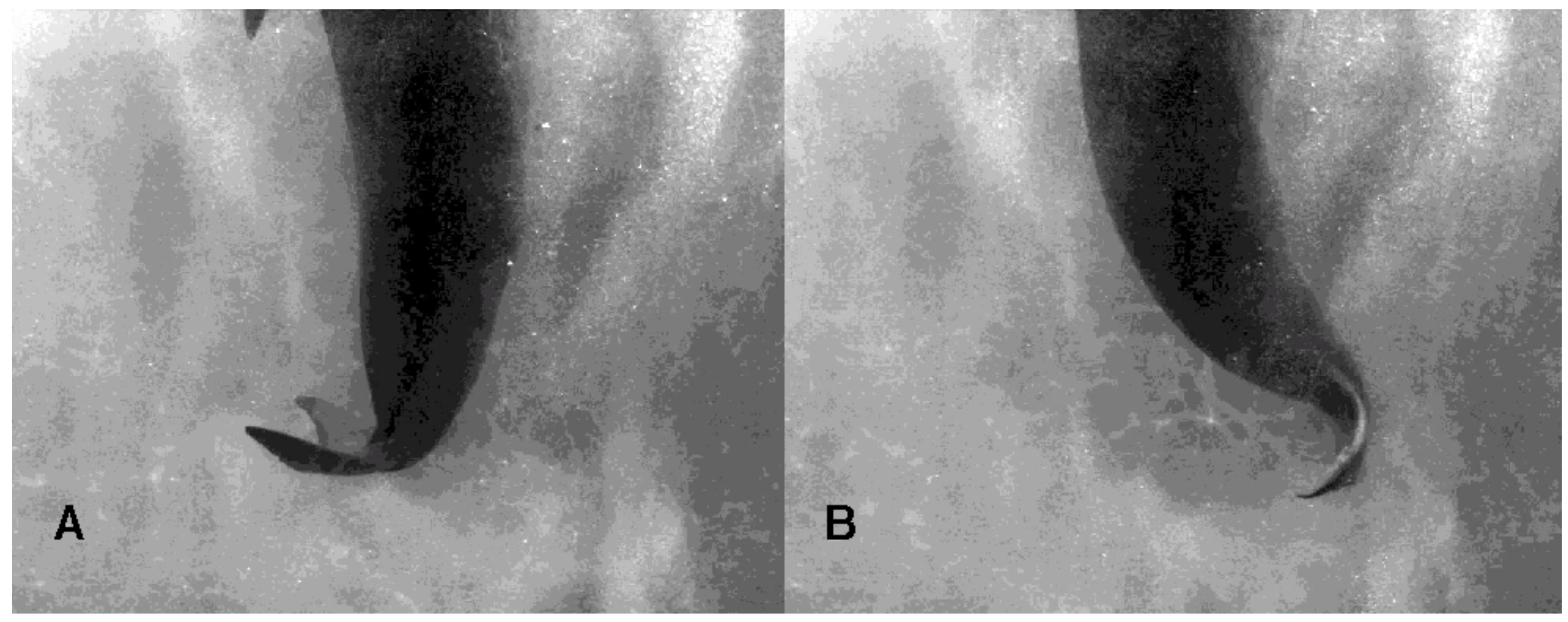
3.1. Tail Stand
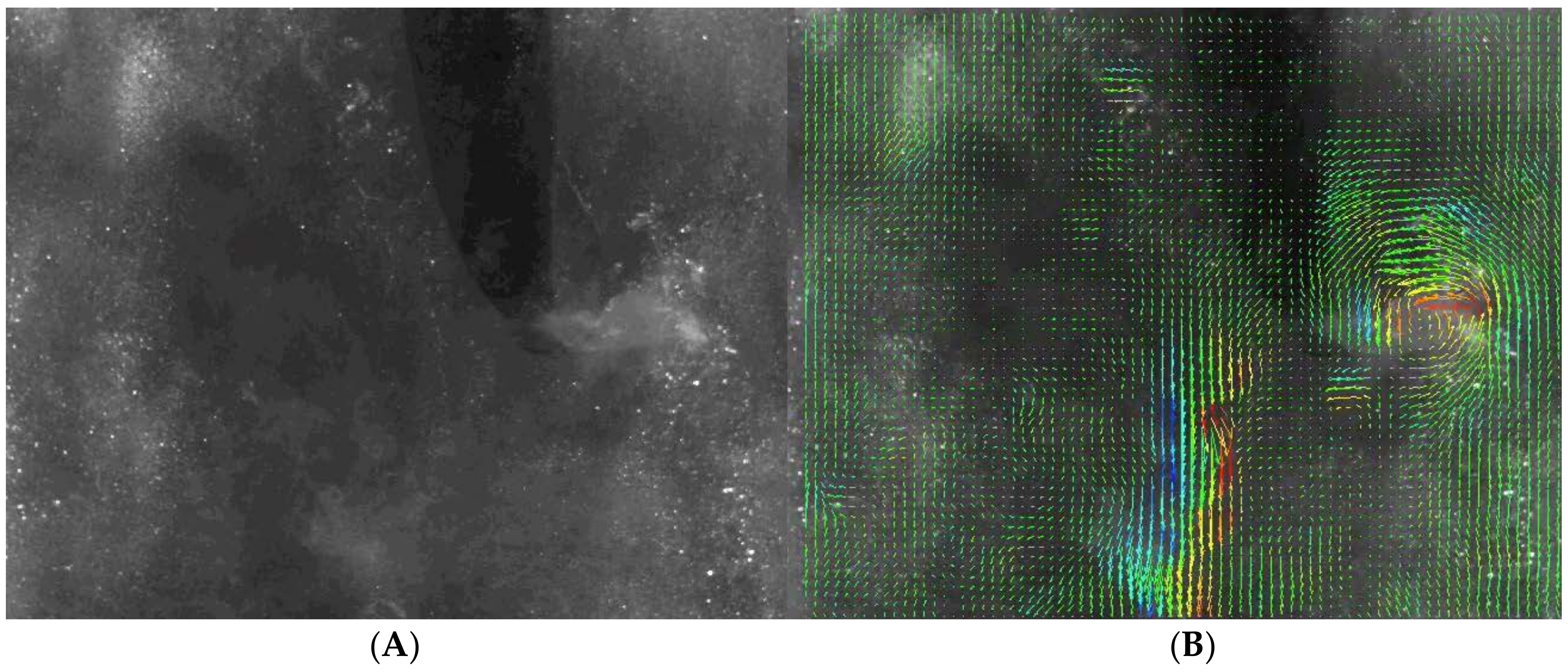
3.2. Bubble DPIV
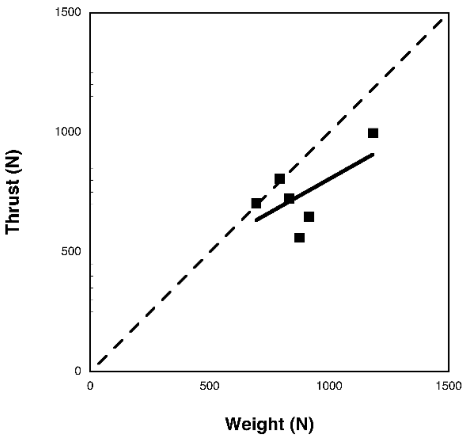
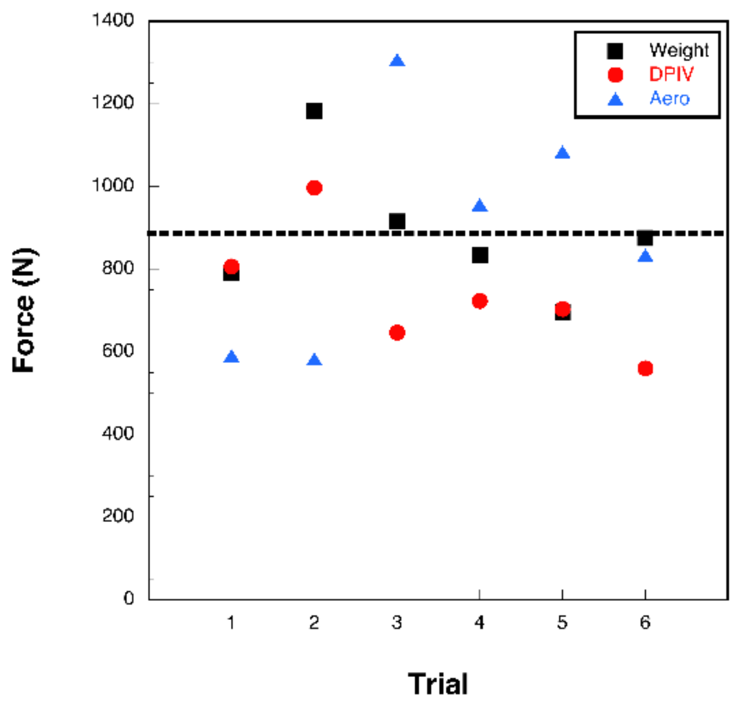
3.3. Aerodynamic Analysis
4. Discussion
5. Conclusions
Author Contributions
Funding
Acknowledgments
Conflicts of Interest
References
- Schultz, W.; Webb, P. Power requirements of swimming: Do new methods resolve old questions? Integr. Comp. Biol. 2002, 42, 1018–1025. [Google Scholar] [CrossRef] [PubMed]
- Wu, T.Y. Hydrodynamics of swimming propulsion. Part 1. Swimming of a two-dimensional flexible plate at variable forward speeds in an inviscid fluid. J. Fluid Mech. 1971, 46, 337–355. [Google Scholar] [CrossRef]
- Weihs, D. Semi-infinite vortex trails, and their relation to oscillating airfoils. J. Fluid Mech. 1972, 54, 679–690. [Google Scholar] [CrossRef]
- Triantafyllou, G.S.; Triantafyllou, M.S.; Grosenbaugh, M.A. Optimal thrust development in oscillating foils with application to fish propulsion. J. Fluids Struct. 1993, 7, 205–224. [Google Scholar] [CrossRef]
- Anderson, J.M.; Streitlien, K.; Barrett, D.S.; Triantafyllou, M.S. Oscillating foils of high propulsive efficiency. J. Fluid Mech. 1998, 360, 41–72. [Google Scholar] [CrossRef]
- Fish, F.E.; Lauder, G.V. Passive and active flow control by swimming fishes and mammals. Ann. Rev. Fluid Mech. 2006, 38, 193–224. [Google Scholar] [CrossRef]
- Fish, F.E.; Legac, P.; Williams, T.M.; Wei, T. Measurement of hydrodynamic force generation by swimming dolphins using bubble DPIV. J. Exp. Biol. 2014, 217, 252–260. [Google Scholar] [CrossRef] [PubMed]
- Webb, P.W. Hydrodynamics and energetics of fish propulsion. Bull. Fish. Res. Board Can. 1975, 190, 1–158. [Google Scholar]
- Rosen, M.W. Experiments with swimming fish and dolphins. Am. Soc. Mech. Eng. 1961, 61-WA-203, 1–11. [Google Scholar]
- Drucker, E.G.; Lauder, G.V. Locomotor forces on a swimming fish: Three-dimensional vortex wake dynamics quantified using digital particle image velocimetry. J. Exp. Biol. 1999, 203, 2393–2412. [Google Scholar]
- Drucker, E.G.; Lauder, G.V. Experimental hydrodynamics of fish locomotion: Functional insights from wake visualization. Integr. Comp. Biol. 2002, 42, 243–257. [Google Scholar] [CrossRef] [PubMed]
- Videler, J.J.; Muller, U.K.; Stamhuis, E.J. Aquatic vertebrate locomotion: Wakes from body waves. J. Exp. Biol. 1999, 202, 3423–3430. [Google Scholar] [PubMed]
- Videler, J.J.; Stamhuis, E.J.; Müller, U.K.; van Duren, L.A. The scaling and structure of aquatic animal wakes. Integr. Comp. Biol. 2002, 42, 988–996. [Google Scholar] [CrossRef] [PubMed]
- Bartol, I.K.; Krueger, P.S.; Thompson, J.T.; Stewart, W.J. Swimming dynamics and propulsive efficiency of squids throughout ontogeny. Integr. Comp. Biol. 2008, 48, 720–733. [Google Scholar] [CrossRef] [PubMed]
- Van Duren, L.A.; Stamhuis, E.J.; Videler, J.J. Copepod feeding currents: Flow patterns, filtration rates and energetics. J. Exp. Biol. 2003, 206, 255–267. [Google Scholar] [CrossRef] [PubMed]
- Abbott, I.H.; von Doenhoff, A.E. Theory of Wing Sections; Dover: New York, NY, USA, 1959. [Google Scholar]
- Lighthill, J. Mathematical Biofluiddynamics; Society for Industrial and Applied Mathematics: Philadelphia, PA, USA, 1975. [Google Scholar]
- Fish, F.E. Balancing requirements for stability and maneuverability in cetaceans. Integr. Comp. Biol. 2002, 42, 85–93. [Google Scholar] [CrossRef] [PubMed]
- Hart, D.P. PIV error correction. Exp. Fluids 2000, 29, 13–22. [Google Scholar] [CrossRef]
- Westerweel, J. Theoretical analysis of the measurement precision in particle image velocimetry. Exp. Fluids 2000, 29, S003–S012. [Google Scholar] [CrossRef]
- Hsu, T.Y. Turbulent Secondary Flow in the Mixed Boundary Corner Formed by a Horizontal Free Surface and a Vertical Solid Wall. Ph.D. Thesis, Rutgers University, New Brunswick, NJ, USA, 2000. [Google Scholar]
- Hsu, T.Y.; Grega, L.M.; Wei, T.; Leighton, R.I. Turbulent kinetic energy transport in a corner formed by a solid wall and a free surface. J. Fluid Mech. 2000, 410, 343–366. [Google Scholar] [CrossRef]
- Legac, P.; Wei, T.; Fish, F.; Williams, T.; Mark, R.; Hutchison, S. Digital particle image velocimetry of mammalian swimming. Phys. Fluids 2008, 20, 091105. [Google Scholar] [CrossRef]
- Stamhuis, E.J.; Nauwalaerts, S. Propulsive force calculations in swimming frogs. II. Application of a vortex ring model to DPIV data. J. Exp. Biol. 2005, 208, 1445–1451. [Google Scholar] [CrossRef] [PubMed]
- Fish, F.E.; Beneski, J.T.; Ketten, D.R. Examination of the three-dimensional geometry of cetacean flukes using CT-scans: Hydrodynamic implications. Anat. Rec. 2007, 290, 614–623. [Google Scholar] [CrossRef] [PubMed]
- Dearolf, J.L.; McLellan, W.A.; Dillaman, R.M.; Frierson, D., Jr.; Pabst, D.A. Precocial development of axial locomotor muscle in bottlenose dolphins. J. Morph. 2000, 244, 203–215. [Google Scholar] [CrossRef]
- Weis-Fogh, T.; Alexander, R.M. The sustained power output from striated muscle. In Scale Effects in Animal Locomotion; Pedley, T.J., Ed.; Academic Press: London, UK, 1977; pp. 511–525. [Google Scholar]
- Josephson, R.K. Contraction dynamics and power output of skeletal muscle. Annu. Rev. Physiol. 1993, 55, 527–546. [Google Scholar] [CrossRef] [PubMed]
- Triantafyllou, M.S.; Triantafyllou, G.S. An efficient swimming machine. Sci. Am. 1995, 272, 40–48. [Google Scholar] [CrossRef]
- Fish, F.E.; Hui, C.A. Dolphin swimming: A review. Mamm. Rev. 1991, 21, 181–196. [Google Scholar] [CrossRef]
- Fish, F.E.; Rohr, J. Review of Dolphin Hydrodynamics and Swimming Performance; SPAWAR Systems Center Pacific: San Diego, CA, USA, 1999. [Google Scholar]
- Fish, F.E. Power output and propulsive efficiency of swimming bottlenose dolphins (Tursiops truncatus). J. Exp. Biol. 1993, 185, 179–193. [Google Scholar]
- Fish, F.E. Comparative kinematics and hydrodynamics of odontocete cetaceans: Morphological and ecological correlates with swimming performance. J. Exp. Biol. 1998, 201, 2867–2877. [Google Scholar] [PubMed]
- Gray, J. Studies in animal locomotion VI. The propulsive powers of the dolphin. J. Exp. Biol. 1936, 13, 192–199. [Google Scholar]
- Fish, F.E. The myth and reality of Gray’s paradox: Implication of dolphin drag reduction for technology. Bioinspir. Biomim. 2006, 1, R17–R25. [Google Scholar]
- Flammang, B.E.; Lauder, G.V.; Troolin, D.R.; Strand, T.E. Volumetric imaging of fish locomotion. Biol. Lett. 2011, 7, 695–698. [Google Scholar] [CrossRef] [PubMed]
- Flammang, B.E.; Lauder, G.V.; Troolin, D.R.; Strand, T. Volumetric imaging of shark tail hydrodynamics reveals a three-dimensional dual-ring vortex wake structure. Proc. Roy. Soc. B 2011, 278, 3670–3678. [Google Scholar] [CrossRef] [PubMed]
- Bartol, I.K.; Krueger, P.S.; Jastrebsky, R.A.; Williams, S.; Thompson, J.T. Volumetric flow imaging reveals the importance of vortex ring formation in squid swimming tail-first and arm-first. J. Exp. Biol. 2016, 219, 392–403. [Google Scholar] [CrossRef] [PubMed]
- Skrovan, R.C.; Williams, T.M.; Berry, P.S.; Moore, P.W.; Davis, R.W. The diving physiology of bottlenose dolphins (Tursiops truncatus) II. Biomechanics and changes in buoyancy at depth. J. Exp. Biol. 1990, 202, 2749–2761. [Google Scholar]
- Alexander, R.M. Principles of Animal Locomotion; Princeton University Press: Princeton, NJ, USA, 2003. [Google Scholar]
- Norberg, U.M. Vertebrate Flight: Mechanics, Physiology, Morphology, Ecology and Evolution; Springer: Berlin, Germany, 1990. [Google Scholar]
- Alexander, D.E. Nature’s Flyers: Birds, Insects, and the Biomechanics of Flight; Johns Hopkins University Press: Baltimore, MD, USA, 2002. [Google Scholar]
- Song, J.; Luo, H.; Hedrick, T. Three-dimensional flow and lift characteristics of a hovering ruby-throated hummingbird. J. R. Soc. Interface 2014, 11, 20140541. [Google Scholar] [CrossRef] [PubMed]
- Warrick, D.R.; Tobalske, B.W.; Powers, D.R. Lift production in the hovering hummingbird. Proc. R. Soc. B 2009, 276, 3747–3752. [Google Scholar] [CrossRef] [PubMed]
- Wolf, M.; Ortega-Jimenez, V.M.; Dudley, R. Structure of the vortex wake in hovering Anna’s hummingbird (Calypte anna). Proc. R. Soc. B 2013, 280, 20132391. [Google Scholar] [CrossRef] [PubMed]
- Pournazeri, S.; Segre, P.S.; Princevac, M.; Altshuler, D.L. Hummingbirds generate bilateral vortex loops during hovering: Evidence from flow visualization. Exp. Fluids 2013, 54, 1439. [Google Scholar] [CrossRef]
- Izrelevitz, J.S.; Triantafyllou, M.S. Adding in-line motion and model-based optimization offers exceptional force control authority in flapping foils. J. Fluid Mech. 2014, 742, 5–34. [Google Scholar] [CrossRef]


| Dolphin | Length (m) | Mass (kg) | Fluke Span (m) | Fluke Chord (m) | Fluke Area (m2) |
|---|---|---|---|---|---|
| Primo | 2.41 | 181.5 | 0.67 | 0.21 | 0.094 |
| Puka | 2.46 | 205.5 | 0.68 | 0.23 | 0.110 |
© 2018 by the authors. Licensee MDPI, Basel, Switzerland. This article is an open access article distributed under the terms and conditions of the Creative Commons Attribution (CC BY) license (http://creativecommons.org/licenses/by/4.0/).
Share and Cite
Fish, F.E.; Williams, T.M.; Sherman, E.; Moon, Y.E.; Wu, V.; Wei, T. Experimental Measurement of Dolphin Thrust Generated during a Tail Stand Using DPIV. Fluids 2018, 3, 33. https://doi.org/10.3390/fluids3020033
Fish FE, Williams TM, Sherman E, Moon YE, Wu V, Wei T. Experimental Measurement of Dolphin Thrust Generated during a Tail Stand Using DPIV. Fluids. 2018; 3(2):33. https://doi.org/10.3390/fluids3020033
Chicago/Turabian StyleFish, Frank E., Terrie M. Williams, Erica Sherman, Yae Eun Moon, Vicki Wu, and Timothy Wei. 2018. "Experimental Measurement of Dolphin Thrust Generated during a Tail Stand Using DPIV" Fluids 3, no. 2: 33. https://doi.org/10.3390/fluids3020033
APA StyleFish, F. E., Williams, T. M., Sherman, E., Moon, Y. E., Wu, V., & Wei, T. (2018). Experimental Measurement of Dolphin Thrust Generated during a Tail Stand Using DPIV. Fluids, 3(2), 33. https://doi.org/10.3390/fluids3020033