Article

Gas–Liquid Two-Phase Flow and Heat Transfer without Phase Change in Microfluidic Heat Exchanger

Department of Optimization of Chemical and Biotechnological Equipment, Saint Petersburg State Institute of Technology, Technical University, Moscovskiy Prospect, 26, 190013 Saint Petersburg, Russia
*
Author to whom correspondence should be addressed.
Fluids 2021, 6(4), 150; https://doi.org/10.3390/fluids6040150
Submission received: 13 March 2021 / Revised: 4 April 2021 / Accepted: 7 April 2021 / Published: 9 April 2021
(This article belongs to the Special Issue Flow and Heat Transfer Intensification in Chemical Engineering)

Abstract

:
This work presents an experimental study of the possibility of intensifying in microfluidic heat exchangers (MFHE) by creating a two-phase segmented flow (gas–liquid). Measurements of convective heat transfer were carried out using an MFHE, consisting of six channels 1 × 1 mm. Experimental studies have shown that segmented flow makes it possible to increase the Nusselt number of a laminar flow in MFHE up to 1.67 and reduce thermal resistance up to 1.7 times compared to single-phase flow. At the same time, it was found that the intensification of heat exchange by a two-phase flow is observed only for the range of the volume fraction of gas from 10 to 30%. In addition, the calculation of the thermal performance criterion, including both thermal and hydraulic parameters (friction factor), also confirmed the promise of using the Taylor segmented flow as a method for single-phase heat transfer intensifying in microchannels.

1. Introduction

With the rapid development of micro- and nano-sized devices, the packing density of the elements and their heat output increase significantly. This results in high operating temperatures, which can significantly reduce the reliability of components and shorten their lifespan. It is predicted that by 2026 the heat flux dissipated in next-generation electronic devices (such as 3D integrated circuits) will exceed 1000 W/cm2 [1] with local hotspots ranging from 1200 to 4500 W/cm2 [2]. Therefore, to keep pace with the current growth trend of microelectronics, efficient cooling methods capable of dissipating large amounts of thermal load from the chip to a surface temperature of less than 125 °C for defense use [3] and less than 85–100 °C for general microelectronics are needed [4].
The microfluidic heat exchanger (MFHE) was proposed in 1981 by Tuckerman and Pease [5] as one of the most promising heat transfer technologies. The MFHE showed significantly higher heat transfer characteristics compared to conventional or macrochannel heat exchangers due to the higher ratio of heat exchange area to volume. The authors found that single-phase liquid cooling can dissipate up to 790 W/cm2. However, the previously developed MFHEs had a problem associated with an uneven temperature distribution over the base (substrate) of the heat exchanger, which adversely affects local overheating. Another disadvantage of heat transfer in single-phase flow microchannels is the low Nusselt number obtained in laminar flow, which is about 4.
In general, there are three approaches to improving heat transfer performance in MFHE [6]: (1) Optimization of MFHE geometry for better coolant distribution. Due to the use of various types of channel configurations [6,7,8], a two-layer or multilayer microchannel heat exchanger [9,10], as well as more complex ones, called fractal structures [11], optimize the location of the inlets and outlets of the coolant [6,12], etc. (2) Flow distribution improves performance mainly due to an increase in the heat exchange area and/or an improvement in the convective heat transfer coefficient [13,14]. (3) Improving the properties of coolants helps by including the use of two-phase flow.
Two-phase flow is of great interest because the heat of vaporization is very high. It was shown [15] that boiling in a flow can dissipate up to 10,000 W/cm2 [16], which is 10 times more heat than in a single-phase flow. This advantage of the boiling flow has found application for heat transfer in devices such as oscillating heat pipe [17], microchannel pulsating heat pipe [18] and others. While boiling in a stream is attractive because it provides a high heat flux at a constant phase transition temperature, it can be difficult to control due to backflow and instability. Another disadvantage of boiling flow is that the water in the heat exchanger is the working fluid, and the boiling point of the water is higher than the operating temperature of most electronic devices. There is a solution to use refrigerants as working fluids, since the boiling point is lower than the boiling point of water. However, refrigerants have a lower cooling capacity due to their lower specific heat and heat of vaporization.
In this work, a two-phase segmented flow as a method of intensifying single-phase heat transfer with water in microchannels was experimentally studied. Segmented flow is a periodic alternation of non-condensable gas bubbles and liquid slugs created in a T-shaped mixer by forcing air into liquid-filled microchannels. The segmented flow [19,20] is widely used in the chemical industry to intensify the process of mass transfer [21,22,23]. More details regarding the structure of a two-phase flow can be found in [24].

2. Experimental Part

2.1. Microfluidic Heat Exchanger Design

In this work, a microfluidic heat exchanger (MFHE) shown in Figure 1 was used. The heat exchanger consisted of 6 channels of square section with a width and height of 1 mm (Wch = 1 mm, Hch = 1 mm), the width of the walls between the channels was also 1 mm (Ww = 1 mm) (see Figure 1c), and the length of the channels was 55 mm (Lch = 55 mm) (see Figure 1, Table 1).
To ensure a uniform heat flux, MFHE was made of high purity copper of the M1 grade (analogous to EN CW004A, DIN ECu57, JIS C1100, UNS C11000). MFHE heating was achieved using a cartridge-type tubular electric heater, which was installed along the heat exchanger (see Figure 1c). In order to reduce the heating of the liquid in the collectors before and after the microchannels, the heater was installed directly along the channels, i.e., the length in the body of the MFHE is equal to 55 mm. Five K-type thermocouples were installed, as shown in Figure 1b, and were used to determine the MFHE wall temperature along the length of the channels. Thermocouples were installed from the bottom wall of one of the extreme channels at a depth of 0.5 mm (see Figure 1c). In further calculations, this thermocouple depth will be taken into account when determining the temperature of the microchannel wall. To study the two-phase flow (G–L) at a distance of 5 mm from the beginning of each of the microchannels (see Figure 1a), there is a hole 0.5 mm in diameter for supplying the gas phase (air). Air is supplied through a manifold, the inlet of which is located on the side surface of the heat exchanger (see Figure 1a). The transparent acrylic glass was pressed from above to the MFHE with screws and sealed using double-sided adhesive tape on an acrylic base (see Figure 1c).

2.2. Experimental Rig

Figure 2 shows an experimental setup for studying the processes of hydrodynamics and heat transfer in MFHE for single-phase and two-phase flows. The MFHE heating section has been wrapped in foam to minimize heat loss and environmental changes. In this case, the upper surface of the MFHE was open (see Figure 2).
In this work, water was used as a continuous phase, and air was dispersed. Water was supplied to the heat exchanger using a gear pump (PMI MG209XK (PMI Technologies, Hangzhou, China)), and the volumetric flow rate of the liquid was determined using a Badger Meter ModMAG M2000 (Badger Meter, Brno, Czech Republic) electromagnetic flowmeter (relative measurement error ± 0.2%). The pressure drop along the MFHE was measured using an NXP MPX5050DP (NXP Semiconductors, Eindhoven, Netherlands) pressure sensor (relative measurement error ± 2.5%). The signal from the pressure sensor was processed using an L-Card E14-140 (L-Card, Moscow, Russia) analog-to-digital converter and recorded by the PowerGraph software package for collecting and processing information. Air was supplied to the channels using a SINO MDT SN-50F6 (Sino MDT, Shenzhen, China) syringe pump equipped with a variable-flow drive and two syringes with a volume of 50 mL each. The use of two syringes was caused by the need to provide a given volumetric flow rate of the dispersed phase.
In this work, the following temperatures were measured: the temperature of the coolant at the inlet and outlet of the MFHE, the wall temperature along the microchannel at five points (the location of the thermocouples is shown in Figure 1), as well as the temperature inside the MFHE insulation (see Figure 2). Pre-calibrated flexible K-type thermocouples were used to measure the listed temperatures. Data registration from thermocouples was carried out using an 8-channel analog input module OWEN MB110-224.8A (OWEN, Moscow, Russia) (response time 500 ms, error ± 0.1 °C). We carried out a series of experiments in the absence of coolant supply to the heat exchanger to verify the accuracy of temperature measurement in the range from 25 to 55 °C. Thus, the deviation was less than 1% (see Appendix A, Figure A1). The boundary condition of constant heat flux in the heating section was achieved by means of a tubular electric heater. In the case of a two-phase flow, photographs were taken through the cover acrylic glass (see Figure 1) for further analysis of the flow of the gas—liquid system.

3. Theoretical Part

In this work, for further calculations and analysis of the results, the actual heat flux, which depends on the temperature of the coolant before and after MFHE, was used. So, the heat power radiated by the heater can be defined as
N = Q · ρ · ( T o u t T i n ) · C p
where Q S P , Q T P is single-phase or two-phase volumetric flow rate of the coolant, m3/s; ρ is coolant density, kg/m3; T i n , T o u t is coolant temperature before and after MFHE, K; C p is specific heat capacity of coolant, J/kg·K, for water C p = 4190 J/kg·K.
Then, the actual heat flux is
q = N / A h
where A h is the cross-sectional area of the heated surface under the channels, m2, since the length of the channels is 55 mm, and the width of six channels is 13 mm (see Figure 1a), A h = 715 mm2.
The average Nusselt number was calculated by the equation as
N u a v g = q · D h ( T w . a v g T f . a v g ) k f
and the local Nusselt number was defined as
N u x = q · D h ( T w . x T f . x ) k f
where T w . a v g , T w . x are the average and local temperature of the channel wall, respectively, K; T f . a v g , T f . x is average and local temperature of the coolant in the channel, respectively, K; k f is coefficient of thermal conductivity of the heat carrier, W/m·K, for water k f = 0.6 W/m·K, D h is hydraulic diameter of the channel, which was found as:
D h = 4 A c h P c h = 2 H c h W c h H c h + W c h
where A c h and P c h are the average cross-sectional area and average perimeter of the flow channel, m2 and m, respectively.
Another important criterion for assessing thermal performance is also the total thermal resistance, which is defined as:
R t h = T w . a v g T f . a v g N
r t h = 1 α a v g
where α a v g is the heat transfer coefficient, W/m2⋅K, which is equal to
α a v g = N u a v g · k f D h
The Reynolds numbers for single-phase and two-phase flows were determined as:
R e S P = u f ρ c D h μ c
R e T P = u T P ρ c D h μ c
where ρ c is the density of the continuous phase, kg/m3; μ c is dynamic viscosity of the continuous phase, Pa·s; u f , u T P is fluid velocity and two-phase flow velocity, m/s, the last of which is calculated as
u T P = u d + u c
where u c , u d are the velocity of the continuous and dispersed phases, respectively, m/s.
The capillary number, Ca, is determined by the following equation
C a = u T P μ c σ
where σ surface tension, N/m, which at the water–air boundary is σ = 72.86 mN/m.
The pumping power of liquid through the MFHE is defined as
N p = Q · P
where P is the pressure drop across the MFHE, Pa. The friction factor f is defined as
f = 2 P ρ u f 2 D h L
To compare the characteristics of the MFHE, the thermal performance criteria is used, which includes both thermal and hydraulic parameters [13]:
η = N u T P . a v g / N u S P . a v g ( f T P . a v g / f S P . a v g ) 1 / 3

4. Results and Discussion

Convective heat transfer measurements were carried out using the MFHE and the setup described in the previous section, with average volumetric flow rates equal to QSP = 0.036–0.54 L/m for a single-phase flow and QTP = 0.036–0.45 L/m for a two-phase flow, which corresponds to the Reynolds numbers ReSP = 100–1500 and ReTP = 100–1250. It was experimentally found that it takes from a few seconds (for pressure) to one minute (for temperature) to stabilize the readings of pressure, temperature and flow sensors. Therefore, for all the experiments, the recording of the sensor readings was carried out two minutes after setting the appropriate flow rate, to be certain that the flow rates and heat flow to the coolant from the electric heater are stabilized.

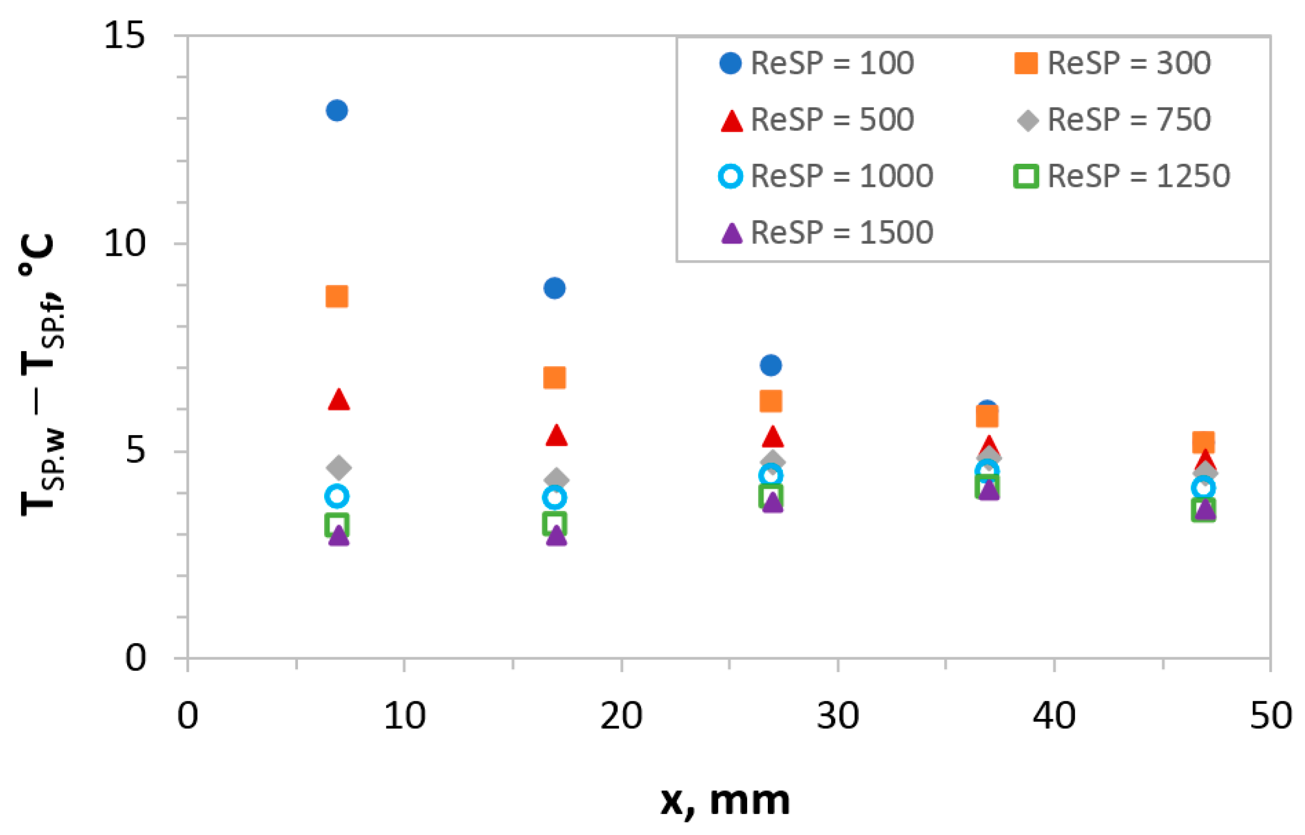
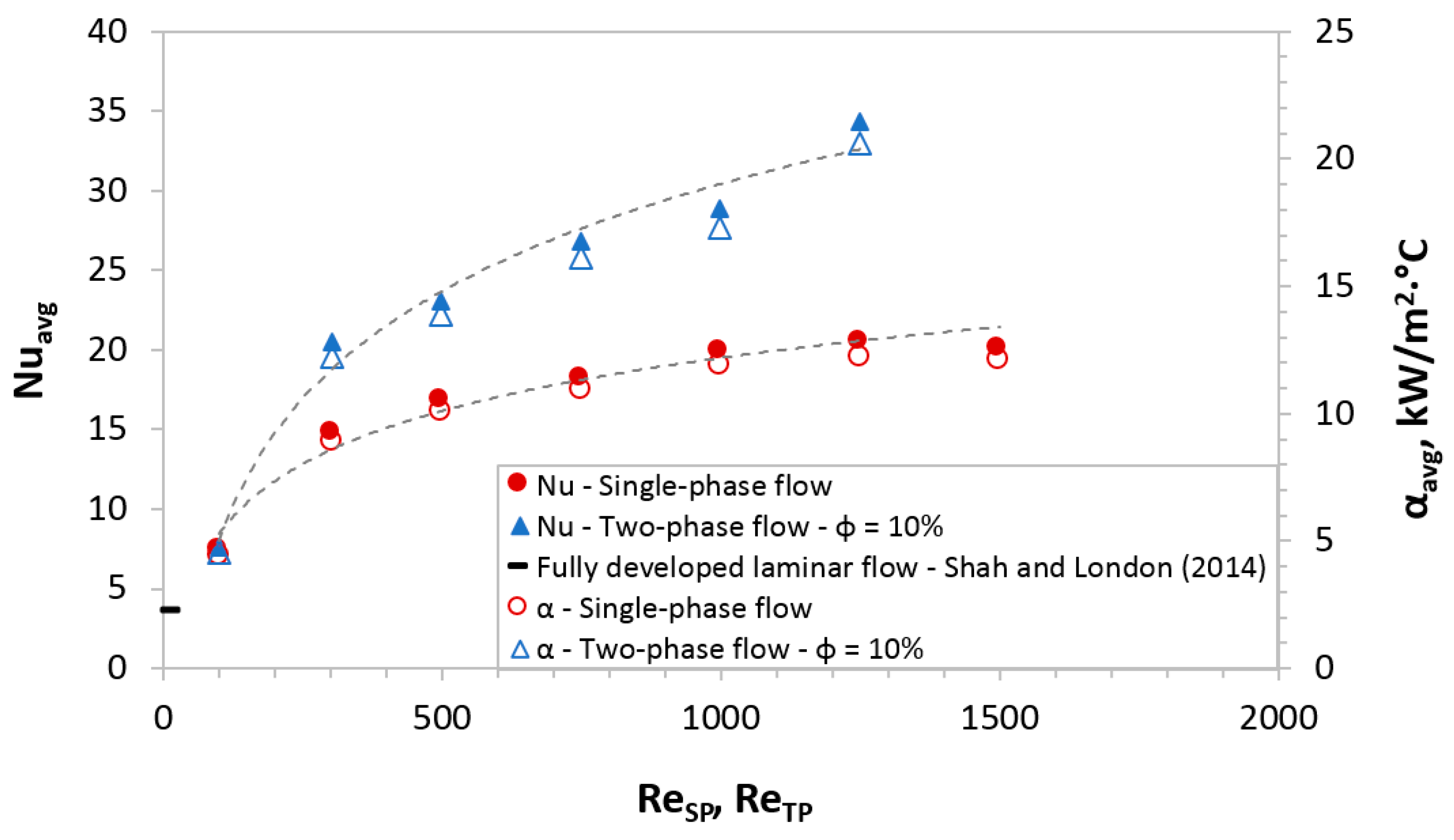
4.1. Heat Transfer in Single-Phase Flow in Microchannels

Heat transfer in a single-phase flow was studied at Reynolds numbers in the range from ReSP = 100 to ReSP = 1500, which corresponds to the fluid velocity in the channel from u f = 0.1 to 1.5 m/s. Taking into account that the thermocouples were installed under the channel at a depth of d z = 0.5 mm, the actual temperature on the channel wall was calculated as
T w . x = T q k s · d z
where T is the temperature measured by the thermocouple, K; k s is the coefficient of thermal conductivity, W/m·K, which for copper is equal to k s = 384.1 W/m·K.
Figure 3 shows the graphs of the dependence of the wall temperature and fluid flow along the length of the MFHE channel for a single-phase flow at ReSP = 100, 300 (see Figure 3a), ReSP = 500, 750 (see Figure 3b), ReSP = 1000, 1250, 1500 (see Figure 3c). Due to the fact that the maximum temperature measurement error is less than 1%, the error bar will not be visible on the graph. So, the error bar is smaller than the size of the dots.
Obviously, with an increase in the Reynolds number, the temperature of the wall and the fluid decreases. So, for ReSP = 1500 compared to ReSP = 100, the average wall temperature decreases from T S P . w . a v g ( R e S P   =   100 ) = 39.2 °C to T S P . w . a v g ( R e S P   =   1500 ) = 29.0 °C, and fluids with T S P . f . a v g ( R e S P   =   100 ) = 31.2 °C to T S P . f . a v g ( R e S P   =   1500 ) = 25.5 °C, which at 1.35 and 1.22 times lower, respectively. Additionally, it can be seen from Figure 3 that temperatures, as expected, increase linearly along the length of the MFHE. In this case, the lower the Reynolds number, the more significant the increase in both the wall temperature and the fluid flow. So, at ReSP = 100, the temperature for T S P . w and T S P . f increases along the length by 2.1 and 10.1 °C, respectively, while for ReSP = 1500 the temperature for T S P . w and T S P . f increases by only 1.4 and 0.8 °C. Figure 3 also shows that with an increase in the fluid velocity in the channels, and correspondingly with an increase in the Reynolds number, the temperature difference between T S P . w and T S P . f decreases significantly. For clarity, we plotted the dependence of the temperature difference on the Reynolds number (see Figure 4).
Let us consider the dependence of the local Nusselt number along the length of the MFHE channel for a single-phase flow on the Reynolds number. Figure 5 shows that the local Nusselt number for ReSP = 100, 300 increases with the MFHE length. Additionally, Figure 5 shows that the local Nusselt number becomes rather uniform over the entire heating length starting from ReSP ≥ 750, with the exception of the first two points (x = 7 and 17 mm), which is explained by the influence of the entrance region. In this case, the effect of the entrance area is more significant the higher the Reynolds number, which is caused by the restructuring of the velocity profile. So, from Figure 5, it can be seen that for the first two points N u S P . x for ReSP = 1500 is almost 2 times higher compared to N u S P . x for ReSP = 300 (24 versus 13). Whereas, for the separate points (x = 25–50), the local Nusselt number is fairly uniform. It can be seen that after ReSP = 300, an increase in the Reynolds number does not give a significant increase in the local Nusselt number, which takes a value equal to about N u S P . x = 17 for ReSP = 300–1500, and the spread N u S P . x for x = 27, 37, 47 is only ±1.7, ±1.4 and ±1, respectively.

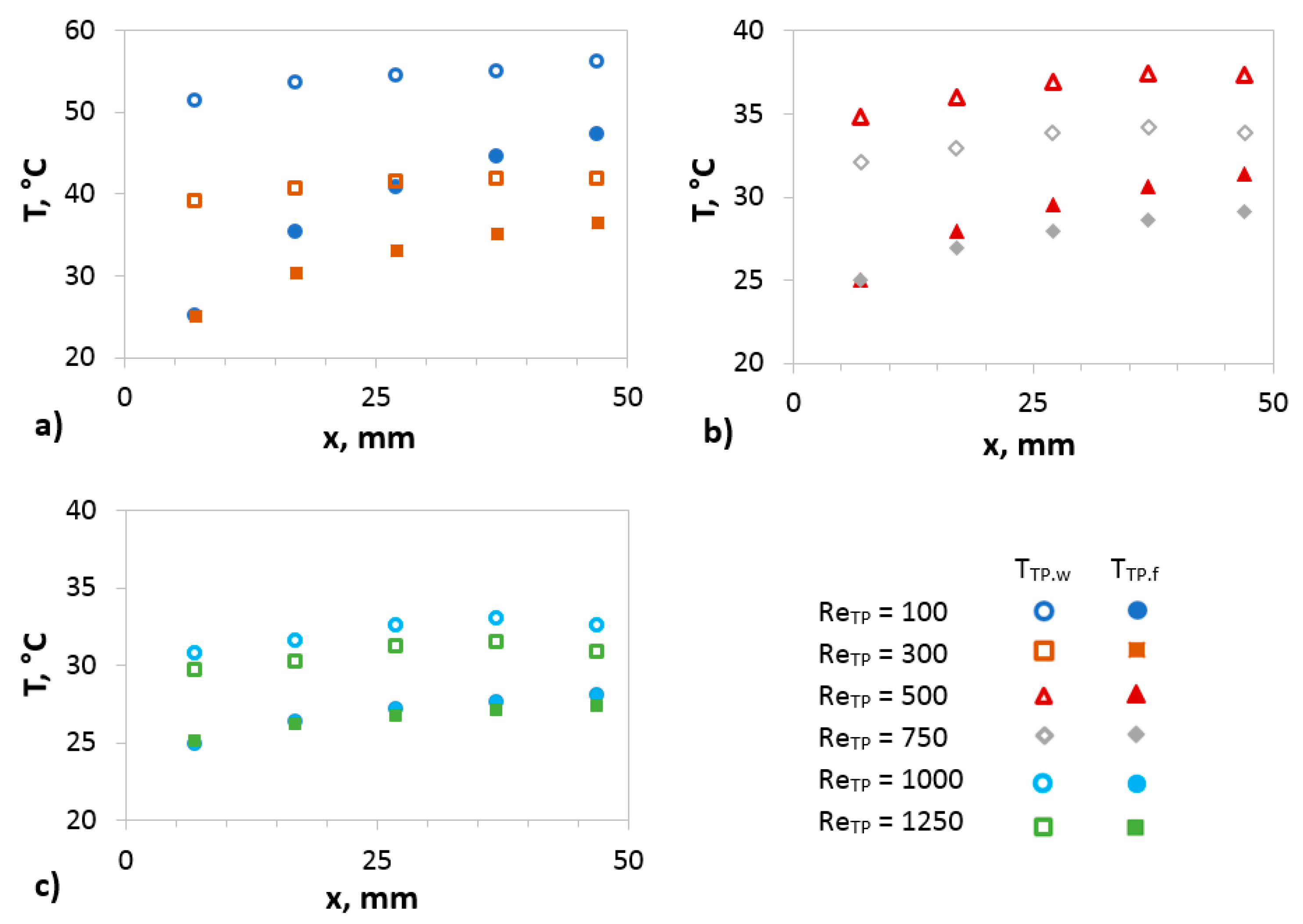
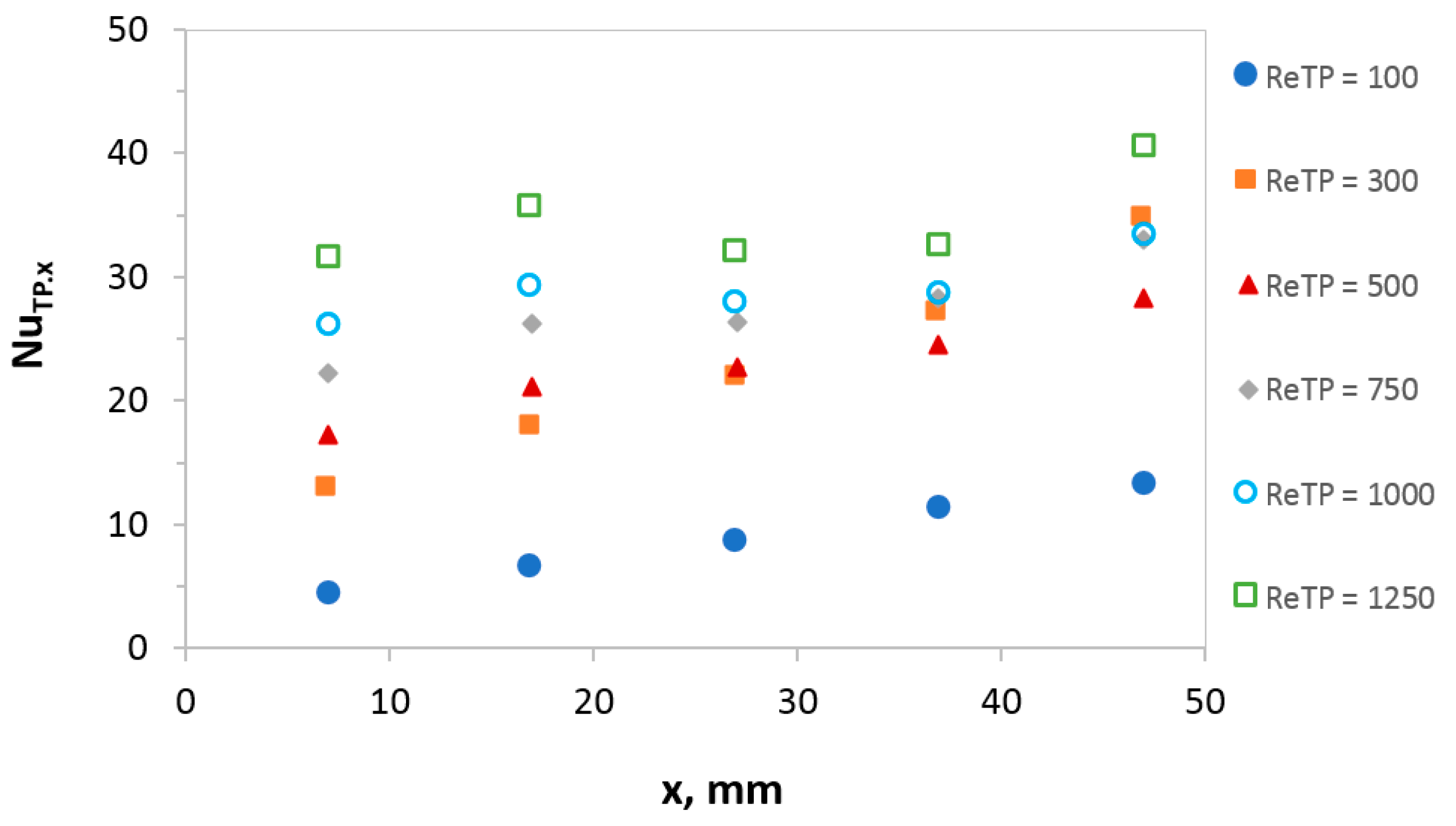
4.2. Heat Transfer in Two-Phase Flow in Microchannels

Heat transfer in a two-phase flow was studied at Reynolds values in the range from ReTP = 100 to ReTP = 1250 at a gas content of 10% and for ReTP = 300 at a gas content of 10 to 40%. As mentioned earlier, segmented flow is widely used in chemical engineering to enhance the mass transfer process. This should accordingly increase the heat transfer due to the same phenomenon of enhanced convection due to the Taylor vortices in liquid slugs. The presence of Taylor vortices in channel requires surface tension to prevail over gravity, which occurs when the Bond number ρ g D h 2 / σ < 3.368 [22] and the capillary number Ca < 0.707 [23]. In our case, the Bond number is 0.135, and the Ca number is in the range from 0.0014 to 0.0172.

4.2.1. Influence of Reynolds Number on the Heat Transfer Efficiency in MFHE

Similarly, to the case for a single-phase flow the dependence of the wall temperature and fluid flow along the length of the MFHE channel for a two-phase flow at φ = 10% for ReTP = 100–1250 was plotted (see Figure 6).
From this graph, it can be concluded that in the case of a two-phase flow, the wall and liquid temperatures become more sensitive to the value of the Reynolds number. So, with an increase in the latter, the temperatures decrease more significantly than for a single-phase flow. For ReTP = 1250, compared with ReTP = 100, the average wall and liquid temperatures decrease by 1.76 and 1.46 times, respectively, while for a single-phase flow these ratios took the values 1.35 and 1.22. Additionally, it can be seen from Figure 6 that temperatures, as expected, increase linearly along the length of the MFHE. In this case, the lower the Reynolds number, the more significant the increase in both the wall temperature and the fluid flow.
The graph of the dependence of the local Nusselt number for a two-phase flow with a gas content equal to φ = 10% is shown in Figure 7. It can be seen from the graph that, as in the case of a single-phase flow, although to a lesser extent, there is an insignificant effect on the first and last points, due to the input effects and instabilities associated with the end of the MFHE. In general, for a two-phase flow, the local Nusselt number is more uniform along the length than for a single-phase flow. Additionally, in contrast to the single-phase flow, the effect of ReTP on the growth of N u T P . x is noticeably more significant. However, the most important conclusion, from the point of view of heat transfer efficiency, which can be drawn from the analysis of the graphs in Figure 5 and Figure 7, is that the segmented flow significantly increases the local N u T P . x and, therefore, leads to an increase and averaged dimensionless heat transfer coefficient N u T P . a v g .
So, from Figure 8, it can be seen that the supply of a two-phase flow to the MFHE (G-L, at φ = 10%) allows an increase in N u T P . a v g and α T P . a v g of 1.67 times compared to single-phase flow. So, for ReTP, ReSP = 1250, the Nusselt number for two-phase and single-phase flows is N u T P . a v g = 34.3 and N u S P . a v g = 20.5, respectively. Figure 8 also shows that for a single-phase flow at ReSP = 500, the average Nusselt number is N u S P . a v g = 18.5 , and a further increase in the flow rate does not significantly affect N u S P . a v g . In this case, for a two-phase flow, an increase in N u T P . a v g from ReTP is observed over the entire investigated range (see Figure 8). For Reynolds tending to zero, the average Nusselt number tends to the fully developed value in the square channels of 3.61 (see Figure 8) [25]. It should also be mentioned that the ratio of the Nusselt number to that of the liquid-only flow obtained in this work is comparable with the data of other researchers. Thus, the N u T P . a v g / N u S P . a v g ratio obtained by the authors lies in the range from 1.63 to 2.88 and from 1.9 to 3.3 obtained experimentally [26,27] and by CFD simulation [28], respectively.
To compare the efficiency of heat transfer in MFHE, another indicator was chosen, the total thermal resistance. Figure 9 shows the dependence of the thermal resistance, calculated by Equations (6) and (7), on the Reynolds criterion for two types of flow. It can be seen from this graph that the thermal resistance for a segmented flow is up to 1.7 times lower than for a continuous liquid flow. In addition, Figure 9 also shows that for a single-phase flow, the thermal resistance is significantly reduced up to and including ReSP = 500, but a further increase in the Reynolds number practically does not affect the Rth and rth. In the case of a two-phase flow, a decrease in Rth, rth is observed over the entire investigated range (see Figure 9).

4.2.2. Influence of Gas Hold-Up on the Heat Transfer Efficiency in MFHE

In order to study the degree of influence of the volumetric gas content on the efficiency of heat transfer, we varied the gas content φ in the range from 10 to 40% at ReTP = 300. Figure 10 shows the dependence of the averaged Nusselt number on the volumetric gas content at ReTP = 300. It can be seen from the graph that the injection of gas in the amount of φ = 10% makes it possible to increase N u a v g by 38% (from 14.76 to 20.43). At a gas content above 10%, the intensification of heat transfer due to a segmented flow of air bubbles rapidly decreases, and at φ = 40%, the value of N u a v g turns out to be lower than for a single-phase flow. It is possible to understand the reason for the obtained dependence by analyzing photographs of flow regimes in microchannels. A visualization of these flow regimes can be seen in Table 2.
We were able to obtain a segmented flow only at φ = 10–30% (see Table 2, a–c). At lower values of the gas fraction, the segmented flow is replaced by a bubbly flow (i.e., bubbles with a diameter less than the channel diameter (see Figure 10)). At the higher values (φ > 30%), we see the formation of an annular rather than slug regime (see Table 2, d, Figure 10). The decrease in the effect of gas injection, exceeding the fraction of 10% in the slug flow (cases b and c), is explained by an increase in the average bubble length (from LB = 1.68 mm at φ = 10% to LB = 2.61 mm at φ = 30%). The fact is that the effect of liquid circulation in slugs is offset by a large fraction of gas, the contribution of which to heat exchange is insignificant, since the heat capacity of the bubbles is much lower than that of the liquid phase.

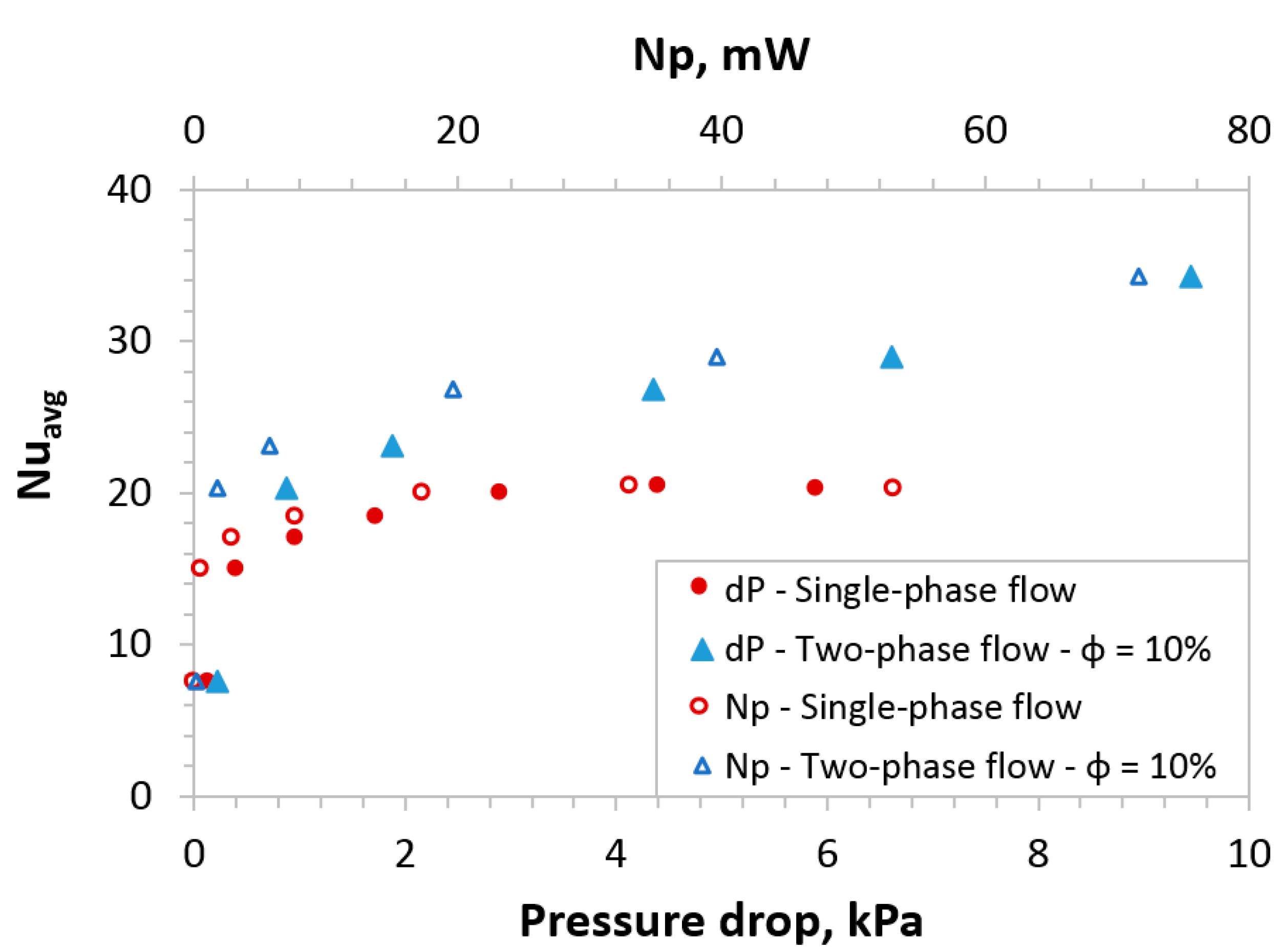
4.3. Single-Phase and Two-Phase Flow Hydrodynamics

The cost of the increase in pressure drop in the MFHE caused by the organization of segmented flow is estimated in Figure 11. It can be seen from the graph that two-phase flow leads to a more significant pressure drop than single-phase flow with the same Reynolds number.
A similar conclusion can be drawn from the obtained dependence of the friction factor, calculated according to Equation (14) from the Reynolds number (see Figure 12).
The segmented flow heat transfer enhancement scheme presented here will only be of interest if it achieves a higher Nusselt number than single phase flow at the same pressure drop and, hence, energy cost. This is confirmed in Figure 13 for pressure drop values ranging from 1 kPa onwards, where the increase in Nusselt number is about 43% using segmented flow instead of single-phase flow, at the same pressure drop.
Figure 13 also shows the dependence of the Nusselt number on the power spent on pumping fluid through the MFHE, calculated according to Equation (13). The obtained dependences also confirm the advantage of using a two-phase flow compared to a continuous flow.
Another comprehensive comparison of heat transfer effectiveness factor is made and shown in Figure 14 using the definition given by Equation (15). Cases in which the values of the thermal performance criteria η exceed 1 indicate conditions under which the two-phase flow allows more heat to be transferred, while consuming less energy, i.e., has great efficiency. In this work, η is less than 1 only with the Reynolds criterion equal to about 100, which is explained by the large friction factor for a two-phase flow (see Figure 13) with equal average Nusselt numbers (see Figure 8).
Figure 14 shows that the data correlate well with Figure 8 and Figure 13 and confirm the prospects of using the Taylor segmented flow as a method for intensifying single-phase heat transfer in microchannels.

5. Conclusions

In this paper, the possibility of intensifying single-phase heat transfer in microfluidic heat exchangers using a two-phase segmented flow is experimentally studied. Measurements of convective heat transfer were carried out using an MFHE consisting of six channels of 1 × 1 mm. Heat transfer in single-phase and two-phase flows was studied at ReSP = 100–1500 and ReTP = 100–1250, respectively.
The ability of gas–liquid non-boiling Taylor flow to increase the heat transfer rate in 1.67 times relative to liquid-only values has been demonstrated in this work. In addition, the thermal resistance for the segmented flow was up to 1.7 times lower than for the continuous liquid flow.
We also found that the improvement in heat transfer occurs only for a certain range of gas content values. Thus, at lower (φ < 10%) or higher (φ > 30%) gas content values, no significant improvement in heat transfer is observed, since the segmented flow is replaced by a bubble or annular flow, respectively. A two-phase flow with a gas content of 10% increases the N u a v g by 38% compared to a single-phase flow (for ReTP = 300). When the gas content is higher than 10%, the heat transfer intensification due to the segmented flow of air bubbles decreases rapidly, and at φ = 40%, the value of N u a v g is lower than for a single-phase flow. Internal recirculations within the liquid slugs have been shown to explain the heat transfer enhancement.
In addition, the cost of increasing the differential pressure in the implementation of the segmented flow was reasonable in the sense that at the same pressure drop values, the segmented flow provides a higher Nusselt number than the single-phase flow. So, for differential pressure values in the range of 1 kPa and beyond, the increase in the Nusselt number is about 43% when using a segmented flow, instead of a single-phase flow, at the same pressure drop value. Another comprehensive comparison using the thermal performance criterion, which includes both thermal and hydraulic parameters, also confirmed the prospects of using the Taylor vortices as a method for intensifying single-phase heat transfer in microchannels.
According to our calculations, the MCHE with the studied geometry is capable of maintaining a heat flux of 70 W/cm2 in the case of single-phase and 120 W/cm2 in the case of two-phase flows. At the same time, MCHE is able to maintain the maximum surface temperature below 85 °C required for general microelectronics [4]. The obtained heat flow for the Taylor flow demonstrates comparable results with the boiling flow in the vapor compression refrigeration flow loop and boiling incipience in pin fin heat sink [16,29]. Therefore, the use of a two-phase gas–liquid flow without a phase transition can be recommended as an alternative to a boiling (vapor–liquid) flow. In addition, it is known that the efficiency of heat transfer in a boiling flow can be significantly increased by reducing the channels hydraulic diameter and using offset strip-fin geometry (the heat transfer coefficient reaches 130,000 W/m2·°C and higher) [16]. It can be assumed that the use of similar methods for intensifying thermal characteristics in the case of a two-phase Taylor flow will provide an effective solution for cooling with large heat fluxes.

Author Contributions

Conceptualization, R.S.A.; methodology, R.S.A.; software, M.P.V.; validation, M.P.V. and R.S.A.; formal analysis, M.P.V. and R.S.A.; investigation, M.P.V.; resources, R.S.A.; data curation, M.P.V.; writing—original draft preparation, M.P.V.; writing—review and editing, R.S.A.; visualization, M.P.V.; supervision, R.S.A.; project administration, R.S.A.; funding acquisition, M.P.V. and R.S.A. All authors have read and agreed to the published version of the manuscript.

Funding

This research was provided by Scholarship of the President of the Russian Federation under the project CП-3109.2021.1.

Institutional Review Board Statement

Not applicable.

Informed Consent Statement

Not applicable.

Data Availability Statement

Not applicable.

Conflicts of Interest

The authors declare no conflict of interest.

Appendix A

Figure A1. Dependence of the wall temperature on the axial arrangement of thermocouples in the MFHE at zero phase flow.
Fluids 06 00150 g0a1

References

  1. Bar-Cohen, A.; Maurer, J.J.; Felbinger, J.G. Darpa’s intra/interchip enhanced cooling (icecool) program. In Proceedings of the 2013 International Conference on Compound Semiconductor Manufacturing Technology, CS MANTECH 2013, New Orleans, LA, USA, 13–15 May 2013. [Google Scholar]
  2. Karayiannis, T.; Mahmoud, M. Flow boiling in microchannels: Fundamentals and applications. Appl. Therm. Eng. 2017, 115, 1372–1397. [Google Scholar] [CrossRef]
  3. Lee, J.; Mudawar, I. Low-Temperature Two-Phase Microchannel Cooling for High-Heat-Flux Thermal Management of Defense Electronics. IEEE Trans. Components Packag. Technol. 2009, 32, 453–465. [Google Scholar] [CrossRef]
  4. Naqiuddin, N.H.; Saw, L.H.; Yew, M.C.; Yusof, F.; Ng, T.C. Overview of micro-channel design for high heat flux application. Renew. Sustain. Energy Rev. 2018, 82, 901–914. [Google Scholar] [CrossRef]
  5. Tuckerman, D.; Pease, R. High-performance heat sinking for VLSI. IEEE Electron. Device Lett. 1981, 2, 126–129. [Google Scholar] [CrossRef]
  6. Vasilev, M.; Abiev, R.; Kumar, R. Effect of microchannel heat sink configuration on the thermal performance and pumping power. Int. J. Heat Mass Transf. 2019, 141, 845–854. [Google Scholar] [CrossRef]
  7. Liu, H.-L.; Qi, D.-H.; Shao, X.-D.; Wang, W.-D. An experimental and numerical investigation of heat transfer enhancement in annular microchannel heat sinks. Int. J. Therm. Sci. 2019, 142, 106–120. [Google Scholar] [CrossRef]
  8. Kumar, R.; Yadav, V.; Abiev, R.S. Concurrent Removal of Heat Transfer and Mass Flow Rate Nonuniformities in Parallel Channels of Microchannel Heat Sink. Theor. Found. Chem. Eng. 2020, 54, 77–90. [Google Scholar] [CrossRef]
  9. Ansari, D.; Kim, K.-Y. Double-Layer Microchannel Heat Sinks with Transverse-Flow Configurations. J. Electron. Packag. 2016, 138, 031005. [Google Scholar] [CrossRef]
  10. Li, X.-Y.; Wang, S.-L.; Wang, X.-D.; Wang, T.-H. Selected porous-ribs design for performance improvement in double-layered microchannel heat sinks. Int. J. Therm. Sci. 2019, 137, 616–626. [Google Scholar] [CrossRef]
  11. Yan, Y.; He, Z.; Wu, G.; Zhang, L.; Yang, Z.; Li, L. Influence of hydrogels embedding positions on automatic adaptive cooling of hot spot in fractal microchannel heat sink. Int. J. Therm. Sci. 2020, 155, 106428. [Google Scholar] [CrossRef]
  12. Chein, R.; Chen, J. Numerical study of the inlet/outlet arrangement effect on microchannel heat sink performance. Int. J. Therm. Sci. 2009, 48, 1627–1638. [Google Scholar] [CrossRef]
  13. Kumar, R.; Abiev, R.; Ribatski, G.; Abdullah, S.; Vasilev, M. New Approach of Triumphing Temperature Nonuniformity and Heat Transfer Performance Augmentation in Micro Pin Fin Heat Sinks. J. Heat Transf. 2020, 142. [Google Scholar] [CrossRef]
  14. Vasilev, M.P.; Abiev, R.S.; Kumar, R. Effect of circular pin-fins geometry and their arrangement on the pressure drop and heat transfer in microchannel heat sink. Methods Eng. Technol. MMET 2020, 8, 60–62. [Google Scholar]
  15. Mudawar, I.; Bowers, M.B. Ultra-high critical heat flux (CHF) for subcooled water flow boiling—I: CHF data and parametric effects for small diameter tubes. Int. J. Heat Mass Transf. 1999, 42, 1405–1428. [Google Scholar] [CrossRef]
  16. Kandlikar, S.G. High Flux Heat Removal with Microchannels—A Roadmap of Challenges and Opportunities. Heat Transf. Eng. 2005, 26, 5–14. [Google Scholar] [CrossRef]
  17. Ma, H.; Cheng, P.; Boswell, J.A. Multiple Thermal Circuit Heat Spreader. U.S. Patent Application 13/640,758, 30 May 2013. [Google Scholar]
  18. Hardesty, R.E. Micro-Channel Pulsating Heat Pipe. U.S. Patent No. 8,919,426, 30 December 2014. [Google Scholar]
  19. Weinmueller, C.; Hotz, N.; Mueller, A.; Poulikakos, D. On two-phase flow patterns and transition criteria in aqueous methanol and CO2 mixtures in adiabatic, rectangular microchannels. Int. J. Multiph. Flow 2009, 35, 760–772. [Google Scholar] [CrossRef]
  20. Thorsen, T.; Roberts, R.W.; Arnold, F.H.; Quake, S.R. Dynamic Pattern Formation in a Vesicle-Generating Microfluidic Device. Phys. Rev. Lett. 2001, 86, 4163–4166. [Google Scholar] [CrossRef] [Green Version]
  21. Chen, W.; Twu, M.; Pan, C. Gas–liquid two-phase flow in micro-channels. Int. J. Multiph. Flow 2002, 28, 1235–1247. [Google Scholar] [CrossRef]
  22. Kreutzer, M.T.; Kapteijn, F.; Moulijn, J.A.; Heiszwolf, J.J. Multiphase monolith reactors: Chemical reaction engineering of segmented flow in microchannels. Chem. Eng. Sci. 2005, 60, 5895–5916. [Google Scholar] [CrossRef]
  23. Abiev, R.S.; Lavretsov, I. Intensification of mass transfer from liquid to capillary wall by Taylor vortices in minichannels, bubble velocity and pressure drop. Chem. Eng. Sci. 2012, 74, 59–68. [Google Scholar] [CrossRef]
  24. Abiev, R.S. Gas-liquid and gas-liquid-solid mass transfer model for Taylor flow in micro (milli) channels: A theoretical approach and experimental proof. Chem. Eng. J. Adv. 2020, 4, 100065. [Google Scholar] [CrossRef]
  25. Shah, R.K.; London, A.L. Laminar Flow Forced Convection in Ducts: A Source Book for Compact Heat Exchanger Analytical Data; Academic Press: Cambridge, MA, USA, 1978; ISBN 0120200511. [Google Scholar]
  26. Betz, A.R.; Attinger, D. Can segmented flow enhance heat transfer in microchannel heat sinks? Int. J. Heat Mass Transf. 2010, 53, 3683–3691. [Google Scholar] [CrossRef]
  27. Walsh, P.A.; Walsh, E.J.; Muzychka, Y.S. Heat transfer model for gas–liquid slug flows under constant flux. Int. J. Heat Mass Transf. 2010, 53, 3193–3201. [Google Scholar] [CrossRef]
  28. Gupta, R.; Fletcher, D.F.; Haynes, B.S. CFD modelling of flow and heat transfer in the Taylor flow regime. Chem. Eng. Sci. 2010, 65, 2094–2107. [Google Scholar] [CrossRef]
  29. Lee, J.; Mudawar, I. Implementation of Microchannel Evaporator for High-Heat-Flux Refrigeration Cooling Applications. J. Electron. Packag. 2005, 128, 30–37. [Google Scholar] [CrossRef]
Figure 1. Microfluidic heat exchanger (MFHE) top view (a), side view with the thermocouples location (b), cross-section of MFHE (c). All dimensions are in millimeters.
Fluids 06 00150 g001
Figure 2. Schematic diagram of the experimental setup to study hydrodynamics and heat transfer in single- and two-phase flow in microfluidic heat exchanger (MFHE).
Fluids 06 00150 g002
Figure 3. Dependence of the wall temperature and fluid flow along the length of the MFHE channel for a single-phase flow at (a) ReSP = 100, 300, (b) ReSP = 500, 750, (c) ReSP = 1000, 1250, 1500.
Fluids 06 00150 g003
Figure 4. Dependence of the temperature difference between the wall and fluid temperatures along the length of the MFHE channel for a single-phase flow at ReSP = 100–1500.
Fluids 06 00150 g004
Figure 5. Dependence of the local Nusselt number on MFHE axial location for single phase flow at ReSP = 100–1500.
Fluids 06 00150 g005
Figure 6. Dependence of wall temperature and fluid flow along the length of the MFHE channel for two-phase flow at φ = 10% for (a) ReTP = 100, 300, (b) ReTP = 500, 750, (c) ReTP = 1000, 1250.
Fluids 06 00150 g006
Figure 7. Dependence of the local Nusselt number on MFHE axial location for two-phase flow at ReTP = 100–1250, φ = 10%.
Fluids 06 00150 g007
Figure 8. Dependence of the average Nusselt number on the Reynolds number (ReSP = 100–1250 for single phase flow and ReTP = 100–1500 for two-phase flow, φ = 10%).
Fluids 06 00150 g008
Figure 9. Dependence of the thermal resistance on the Reynolds number.
Fluids 06 00150 g009
Figure 10. Dependence of the average Nusselt number on the gas hold-up at ReTP = 300. Bubbly, slug and annular flows (experimental data).
Fluids 06 00150 g010
Figure 11. Pressure drop for single phase and two-phase flow versus Reynolds number.
Fluids 06 00150 g011
Figure 12. Friction factor for single phase and two-phase flow versus Reynolds number.
Fluids 06 00150 g012
Figure 13. Dependence of the average Nusselt number on the pressure drop for single phase and two-phase flow.
Fluids 06 00150 g013
Figure 14. Dependence of the thermal performance criteria η on the Reynolds number (ReSP, ReTP = 100–1250, at φ = 10% for two-phase flow).
Fluids 06 00150 g014
Table 1. Geometrical dimensions of MFHE.
ParameterLch, mmWch, mmWw, mmHch, mm
Value55111
Table 2. Visualization of two-phase flows at a gas content φ = 10–40%.
Case(a)(b)(c)(d)
Gas hold-up (%)10203040
Flow regimeslugslugslugannular
Average length LB (mm)1.682.362.61
Average length LS (mm)2.312.811.22
Average length LUC (mm)3.994.173.83
(a)
Fluids 06 00150 i001
(c)
Fluids 06 00150 i002
(b)
Fluids 06 00150 i003
(d)
Fluids 06 00150 i004
Publisher’s Note: MDPI stays neutral with regard to jurisdictional claims in published maps and institutional affiliations.

