
Theoretical Hydrodynamic Analysis of a Surface-Piercing Porous Cylindrical Body


Laboratory for Floating Structures and Mooring Systems, Division of Marine Structures, School of Naval Architecture and Marine Engineering, National Technical University of Athens, 9 Heroon Polytechniou Avenue, GR 157-73 Athens, Greece
*
Author to whom correspondence should be addressed.
Fluids 2021, 6(9), 320; https://doi.org/10.3390/fluids6090320
Submission received: 3 August 2021
/
Revised: 2 September 2021
/
Accepted: 6 September 2021
/
Published: 7 September 2021
(This article belongs to the Special Issue Hydrodynamics and Its Interaction with Structures)
Abstract
:In the present study, the diffraction and the radiation problems of water waves by a surface-piercing porous cylindrical body are considered. The idea conceived is based on the capability of porous structures to dissipate the wave energy and to minimize the environmental impact, developing wave attenuation and protection. In the context of linear wave theory, a three-dimensional solution based on the eigenfunction expansion method is developed for the determination of the velocity potential of the flow field around the cylindrical body. Numerical results are presented and discussed concerning the wave elevation and the hydrodynamic forces on the examined body for various values of porosity coefficients. The results revealed that porosity plays a key role in reducing/controlling the wave loads on the structure and the wave run-up, hence porous barriers can be set up to protect a marine structure against wave attack.
1. Introduction
Over the past few decades, a substantial research interest has been driven towards the effectiveness of porous structures in reducing both the transmitted and reflected wave heights. By comparing with impermeable bodies, the wave loads on porous structures are relatively reduced, whereas the wave reflections are decreased, hence porous surfaces can be set up to protect a marine structure against wave attack.
Considering the porous effect, this was initially studied in terms of porous rubble-mound breakwaters, applied to protect harbors and shores from wave action. Indicative studies on the wave reflection/transmission and dissipation of energy inside porous breakwaters, applying proper eigenfunction expansions in the water region in front and within the porous medium, and behind the breakwater, were performed by [1,2,3,4], to name a few. In [5], the theory of wave transmission and reflection by an infinitely long porous structure was extended for oblique wave incidence, whereas in [6] a semi-porous cylindrical breakwater was examined, using the eigenfunction expansion method, concluding that the wave loads on the breakwater were reduced due to the semi-porous portion of the cylinder. Subsequently, several studies followed, examining theoretically and experimentally the induced wave-flow in a porous breakwater and its capability to dissipate the wave energy and to minimize the environmental impact [7,8,9,10,11]. Furthermore, porous plates have also been studied in the literature due to their capability of free exchange of water or marine species. Initially, a porous-wavemaker theory was developed in [12] and [13] to analyze small-amplitude surface waves produced by oscillations of a porous plate, whereas the reflection and transmission of waves of small amplitude by a rigid porous plate fixed in an open channel of a constant depth were presented in [14]. In [15], a boundary element method was applied on the wave diffraction of a submerged porous plate demonstrating that a plate with a proper porosity could attenuate the reflection while keeping the transmission at a low level. Several studies have followed, dealing with the solution of scattered and radiation problems of submerged and/or floating elastic porous disks, i.e., [16,17,18,19,20]. In addition, in [21,22], the hydroelastic behavior of a flexible submerged porous plate has been studied for wave energy absorption.
As for the interaction of waves with permeable/porous cylindrical bodies, Wang and Ren [23] were the earliest to study the wave interactions with a concentric surface piercing porous outer cylinder protecting an impermeable inner cylinder. They concluded that the presence of the outer porous cylinder reduced the hydrodynamic forces on the inner cylinder as compared to their counterparts when it was exposed to a direct wave impact. In [24], an analytical methodology on evaluating the wave kinematics and loads on vertical piles with porous bottom protection was introduced, whereas in [25] the water–wave interactions with an array of surface-piercing, bottom-mounted porous cylinders were evaluated using the eigenfunction expansion method. This study was extended in [26] for the case of a floating porous cylinder, concluding that the permeability and the size of the porous region have a considerable influence on the hydrodynamic forces. The wave diffraction problem around a cylinder with an upper porous wall and an inner impermeable column was examined in [27]. The results from this study demonstrated that the increase on the porous coefficient of the outer column reduced the wave elevation around the cylinder and the wave loads on it. Comparisons between experimental and numerical results were presented in [28] concerning the diffraction of linear waves around a group of dual porous cylinders, and in [29] regarding the hydrodynamics of a bottom seated impermeable cylinder encircled by a porous cylindrical surface. A semi-submerged porous circular cylinder was examined in [30] by means of the eigenfunction expansion. Applying the Haskind relations, a new component of damping was found, caused by the porosity in addition to the conventional wave radiating damping. Park et al., [31] solved the diffraction problem of an array of truncated porous circular cylinders to calculate the exciting forces on each body, whereas in [32,33] the wave interactions with a single or arrays of porous circular cylinders with or without an inner porous plate were theoretically and experimentally investigated. In addition, an array of partially porous, surface-piercing cylindrical bodies were examined in [34]. Here, the partial porous cylinder was composed of a porous-surfaced body near the free surface and an impermeable-surfaced body with an end-capped rigid bottom below the porous region. An optimal ratio of the porous portion to the impermeable portion was adopted to design an efficient body with minimal hydrodynamic impact. The effects of the porous coefficient—the cylinder’s draught and radius and the water depth on the hydrodynamic loads of a truncated compound cylinder with an upper porous sidewall and an inner impermeable column—were examined in [35]. The study focused on the selection of proper geometrical parameters in order to decrease the hydrodynamic loads on the porous cylinder. Furthermore, wave forces on porous geometries with linear and quadratic resistance laws were presented in [36,37], whereas in [38] the image method was applied to study the effect of a vertical breakwater on the hydrodynamics of a bottom-mounted surface-piercing porous cylinder placed in front of the wall. Recently, the diffraction and radiation problems of a semi-porous truncated cylinder in finite water depth was solved in [39,40,41], employing the method of the separation of variables and matched eigenfunction expansions for the velocity potentials around the cylinder. Additionally, in [42] a boundary element method model was presented on structures composed of solid and porous surfaces applying a linear or quadratic pressure-velocity relation, whereas an efficient method to remove irregular frequencies in the wave-porous structure interactions based on the null-field approach was presented in [43].
Porous cylinders are also related to fish-farm cages, the performances of which, in currents and waves, have been widely studied in the literature. Noteworthy examples of recent works in chronological order are [44,45,46,47,48,49]. In these studies a porous flexible circular cylinder is assumed, simulating the fish net. Furthermore, semi-porous truncated cylindrical structures have been adopted for semi-submergible fish-cage solutions, in which the coaxial cylindrical body is conceived to support the possible installation of a Wind Turbine or to mount tendons of a TLP type mooring system [50,51].
In the present study, a floating porous cylindrical body is examined that consists of a compound cylinder with an upper porous sidewall and an inner cylindrical impermeable column (see Figure 1). The porous surface is assumed to be inflexible and free-surface piercing, whereas the body bottom is considered to be impermeable. A theoretical formulation is presented, which is suitable for solving the linearized diffraction and radiation problems around the porous body in the frequency domain. The method of matched axisymmetric eigenfunction expansions is used to solve the relevant hydrodynamic problems in surge, heave, and pitch. According to this method, the flow field around and inside the body is subdivided into coaxial ring-shaped fluid regions, in each of which appropriate series representations of the velocity potential can be established. The linear Darcy’s law is applied for the boundary conditions on the porous surface, whereas the various potential solutions are matched by the requirements for continuity of the hydrodynamic pressure and radial velocity along the vertical boundaries of adjacent fluid regions, as well as by fulfilling appropriate kinematical conditions at the impermeable vertical walls of the body. The accuracy of the present method is validated with comparisons of available data from the literature concerning the exciting forces and the hydrodynamic coefficients of similar porous bodies, as the examined one.
Subsequently, this work is focused on the theoretical estimation of the drift forces on the examined floating porous cylindrical body in the presence of regular waves. Drift forces are second-order forces, time independent if the motion of the body is harmonic or slowly varying if the body is subjected to the action of random waves. They are generally small in magnitude compared to their first-order oscillatory counterparts; as a result, they do not influence the body’s oscillatory motions. On the other hand, in situations where there is a lack or very small hydrostatic restoring forces, the drift forces may cause large excursions of the body from its mean position if they act over sufficiently long periods of time. In the present work the direct integration method [52] is applied for the evaluation of the drift forces acting on the examined porous body. It is clearly demonstrated by the presented results that, depending on the wave frequency of the incoming wave train, the presence of the porous surface can reduce the wave loads on the body.
The present work is structured as follows: Section 2 formulates the solution of the corresponding diffraction and radiation problems, whereas in Section 3 the hydrodynamic forces and the mean second-order forces, i.e., the drift forces, are evaluated. Section 4 is dedicated to the presentation of the wave loads on the porous body for several values of porous coefficients. Finally, the conclusions are drawn in Section 5.
2. Formulation of the Hydrodynamic Problem
A porous free-surface piercing cylindrical body with a vertical axis of symmetry and impermeable bottom is exposed to the action of regular waves with amplitude (H/2), wave number k and frequency ω, in a constant water depth d. The distance between the bottom of the porous body and the seabed is denoted by h, whereas the distance between the bottom of the porous surface and the seabed is denoted by h1. The radius of the cylindrical porous surface is denoted by α, and the radius of the coaxial cylinder by b. A cylindrical co-ordinate system is introduced with origin at the seabed, coinciding with the body’s vertical axis of symmetry (see Figure 1). Viscous effects are neglected, and the fluid is assumed incompressible and the flow irrotational. The motions of the fluid and the body are assumed to be small, so that the linearized diffraction and radiation problems can be considered.
The examined porous cylindrical body is assumed to perform a three-degree of freedom motion in the wave propagation plane under the action of regular waves, i.e., two translational (surge, , heave, ) and one rotational (pitch, ). The fluid flow is described by the velocity potential:
The potential in Equation (1) is formulated separately in each of the three fluid regions surrounding the body, i.e., (a) fluid region I: ; (b) fluid region II: ; and (c) fluid region III: (see Figure 1). It follows that:
In Equation (2), stands for the velocity potential of the undisturbed incident harmonic wave, whereas denotes the scattered wave potential for the body restrained in waves. Further, we denote:
![Fluids 06 00320 g001]()
Figure 1.
3D representation of the examined porous compound cylindrical body.

Furthermore, in Equation (2), (j = 1, 3, 5) is the radiation potential resulting from the forced body oscillations in the j-th mode of motion with unit velocity amplitude, whereas is the complex velocity amplitude of body motion in the j-th direction.
The undisturbed velocity potential of an incident wave train propagating along the positive axis can be expressed using Jacobis’s expansion, i.e.,:
In Equation (4), denotes the m-th order Bessel function of first kind and the Neumann’s symbol, whereas the frequency ω and the wave number k are connected by means of the dispersion relation.
Similar to Equation (4), the diffraction potential of the flow field around the porous body equals to:
As far as the radiation potentials are concerned, these can be expressed, in accordance with Equation (5), as:
In Equations (5) and (6), the functions are the principal unknowns of the problem, in which the first subscript l = D, 1, 3, 5, denotes the respective boundary value problem, whereas the second one indicates the values of modes m that should be taken into account within the solution process.
The complex velocity potentials , (j = 1, 3, 5), k = I, II, III have to satisfy the Laplace equation in the corresponding fluid domain together with the zero normal velocity on the seabed and the free-surface boundary condition, i.e.,:
Additionally, the kinematic conditions on the body’s impermeable wetted surface, S, in its average position, should be satisfied, i.e.,:
Additionally, the Sommerfeld radiation condition has to be fulfilled at the far-field for the radiation and scattering potentials () [53]. In Equation (8), ∂/∂n denotes the derivative in the direction of the outward unit normal vector, , to the mean wetted- surface of the body and nj is the generalized normal vector defined as: , where r is the position vector with respect to the origin of the coordinate system.
On the sidewall porous surface of the cylindrical body, the fluid flow passing through the porous surface is assumed to obey Darcy’s law. It should be noted that the normal flow velocity is continuous and linearly proportional to the pressure difference through the porous boundary [25]. Hence, the boundary condition on the permeable wetted surface is:
In Equation (9), μ is the coefficient of the dynamic viscosity, γ is a material constant having the dimensions of length expressed as function of surface permeability and its length and ρ is the fluid density, respectively [12], whereas the term is introduced in Equation (8). Introducing , where k is the wave number, Equation (9) can be written as:
The dimensionless porous coefficient is a complex number, i.e., with being its real and its imaginary part [54]. It expresses a measure of the porosity effect. For the porous surface is assumed to be impermeable, whereas for the surface is, literally, completely permeable to fluid (i.e., no presence of the surface). Furthermore, the parameter is considered to be a real number when the resistance effect dominates over the inertial effect of the fluid inside the porous material. On the other hand, when the inertial effect dominates over the resistance effect, becomes an imaginary number [42]. Equations (9) and (10) are valid for a small solidity ratio at which the fluid inertial effect is predominant. By a set of experiments in [36], the porous coefficient was related to the opening rate τ of the material (i.e., the ratio between the area of the opening holes and the total area) as well as the wave slope , i.e.,:
In the present paper a linear pressure drop is assumed across the porous boundary. Nevertheless, several studies (i.e., [36,37,42] to name a few) assume a quadratic pressure drop across the porous surface. In quadratic formulation the linear drag term is neglected and the pressure drop is assumed to be the sum of a quadratic drag term due to turbulent dissipation and an inertial term due to acceleration of the flow through the openings.
Moreover, both the velocity potential and its derivative must be continuous at the vertical boundaries of adjacent fluid regions (see Figure 1). Accordingly, it follows that:
The determination of the velocity potential for an impermeable compound cylindrical body has been presented thoroughly in previous studies [53,55,56], to name a few. Thus, since the same process is followed here for the case of a porous cylindrical body, the solution methodology is not further detailed in the present work. Nevertheless, in the following, the appropriate series representations of the functions for the wave potentials in each fluid region around the porous body are presented:
Infinite fluid domain (Type I):
where:
In Equations (14) and (15), stand for the m-th order Hankel function of the first kind and the modified Bessel function of the second kind, respectively, whereas equals to: Furthermore, the eigenfunctions and read:
The terms are roots of the transcendental equation: . This equation has an imaginary and an infinite number of real roots. Here, the imaginary root , and the positive real roots are considered.
Second fluid domain (Type II):
In Equation (17) the term equals to [53]:
The terms are functions in the radial direction that involve modified Bessel functions, and they are given in Appendix A. The eigenfunctions Zi read:
The terms are roots of the equation: , with the imaginary one considered to be first.
Third fluid domain (Type III):
The term equals to [53]:
In Equation (22), Im is the m-th order modified Bessel function of first kind.
Applying the Galerkin’s method the expressions for the velocity potential are matched by continuity requirements of the hydrodynamic pressure and radial velocity along the common vertical boundaries of adjacent fluid regions (see Equations (12) and (13)), as well as by fulfilling the kinematic conditions at the vertical walls (porous or impermeable) of the body (see Equations (8) and (10)). This formulation delivers the linear systems of equations for the determination of the unknown Fourier coefficients, in each fluid domain. This numerical procedure is briefly described in Appendix B.
3. Hydrodynamic Forces
Having determined the velocity potential in each fluid region around the porous cylindrical body, the hydrodynamic forces in the x and z directions and the overturning moment around y axis can be determined from the pressure distribution given by the linearized Bernoulli’s equation.
The horizontal exciting forces, Fx, on the porous body can be decomposed into four terms: (a) the horizontal exciting forces on the coaxial cylinder, Fxb, i.e., for , and r = b; (b) the horizontal exciting forces on the inner side of the porous surface, , i.e., for , and ; (c) the horizontal exciting forces on the outer side of the porous surface, , i.e., for , and ; and (d) the horizontal exciting forces on the impermeable surface, Fxim, i.e., for , and r = a. These can be summarized according to:
The vertical forces acting on the porous cylindrical body, FZ, are equal to the sum of the forces on the upper surface, i.e., , and the lower surface, i.e., ,. Hence:
The overturning moment on the porous body, , around a horizontal axis lying at an arbitrary distance z = e from the seabed, is composed by Ms and Mb that originate from the pressure distribution on the body’s vertical walls (i.e., porous and impermeable) and on its impermeable bottom, respectively:
The hydrodynamic reaction forces and moments acting on the examined porous cylindrical body in the i-th direction due to its sinusoidal motion with frequency ω and unit amplitude in the j-th direction, are obtained by:
In Equation (27), the term is being defined by Equation (8), whereas m = 0 stands for the symmetric modes of motion, i.e., for the heave radiation problem, while m = 1 refers to the antisymmetric motion-radiation problems (surge and pitch).
The complex force may be written in the form:
where are the added mass and damping coefficients, respectively, both real and dependent on frequency ω.
Aside from the hydrodynamic forces of first-order on a porous cylindrical body, the present paper also deals with the evaluation of the drift wave loads, on the porous body. Herein, the direct integration method is applied [52], providing expressions for all the components of the second-order steady forces and moments. This method was extended in [57,58,59] to account for missing quadratic terms of hydrostatic nature. The drift forces are derived by the direct integration of the fluid pressure upon the instantaneous wetted surface of the porous body, retaining all terms up to the second order.
In Equation (29), the bars denote the time average, whereas S is the body’s mean wetted surface. The terms ρ and g denote the water density and the gravity acceleration, respectively. The term is the unit normal pointing outwards of the body, M is the generalized mass matrix, and is the vector of the first-order translations at a point on the body’s wetted surface, which is composed by the superposition of translational motions of the bodies’ center of gravity and the rotations around it. Additionally, the term stands for the rotational transformation matrix, whereas the term is the first-order translational acceleration of body’s center of gravity and is the first-order relative wave elevation with respect to the transposed static water line, WL, of the body. The term is the vertical distance of the center of gravity, G, from the seabed; the term is the first order pitch motion about the reference point G. Finally, is given in Equation (1), while denotes its time derivative.
4. Numerical Results
4.1. Validation
This section is dedicated to confirming the validity of the presented theoretical method and its numerical implementation. The results from the present methodology are compared with corresponding data, which are available in the literature. The depicted numerical results are obtained using the HAMVAB code [60] developed in Fortran. The CPU time for each wave frequency related to the diffraction and the radiation problems is less than a second. Herein, for the case of the I and II ring elements, I = 40 terms were used, while for the III ring element n = 60 terms, whereas the modes m = 7.
In Figure 2 the exciting forces on a floating porous cylindrical body without the presence of the coaxial cylinder (i.e., b = 0, see Figure 1) are presented and compared with the results reported in [32]. Here, the examined cylinder is of radius α and draught (d − h1)/α = 2. The cylinder is situated in a liquid domain of depth d = 100α/3. The non-dimensional porous coefficient is assumed to be a real number and equal to G = 1.432. The thickness of the impermeable bottom of the cylinder is assumed to be negligible, i.e., h1 ≈ h, and the wave train is considered propagating at zero angle. The depicted numerical results concerning the exciting wave forces have been normalized by ρgα2(H/2), while the exciting wave moments have been normalized by ρgα3(H/2). Furthermore, in Figure 3 the hydrodynamic coefficients of the examined porous cylinder are presented and compared, again, with the results reported in [32]. The coefficients have been normalized by (ρα3) and (ωρα3) for the added mass and damping terms, respectively.
The drift forces on a floating porous cylinder (i.e., b = 0) are also presented. For comparisons, the results reported in study [61] are exploited. The examined cylinder of radius α and draught (d − h1)/α = 1, is floating at water depth d = 3α. The thickness of the impermeable bottom of the cylinder is assumed to be negligible, i.e., h1 ≈ h. Two different non-dimensional values of the porous coefficient G are considered, i.e., G = 0 and G = 1.353. Figure 4 shows the non-dimensional horizontal drift force on the porous cylinder that is given, normalized by 2ρgα(H/2)2/π.
Figure 2 and Figure 3 show a favorable agreement between the calculations obtained by the present method and the results reported in [32]. The same holds for the calculations of the drift loads depicted in Figure 4. Here, comparisons are made with the results reported in reference [61]. Therefore, it can be concluded that the present model can effectively anticipate the hydrodynamic loads and the hydrodynamic coefficients associated with the concerned porous cylindrical body.
4.2. Test Cases
4.2.1. Coaxial Bottom-Mounted Porous Cylindrical System
The method developed in the present study is initially applied for a bottom-mounted, surface-piercing, impermeable cylinder surrounded by an exterior porous cylindrical cell. The porous cylindrical surface has radius α, while the radius of the coaxial impermeable cylinder is b = 0.5α. Here, h1 = h = 0 (i.e., the porous surface is assumed to be bottom-mounted). An incident wave train is considered, propagating at an angle of zero in a fluid field of depth d = 3b. Several values of opening ratios τ are examined. Table 1 lists practical values of τ as a function of the porous coefficient G (see Equation (11)) for wave slope ε = 0.05 [36]. The G values are considered in Figure 5, Figure 6 and Figure 7 and are used to evaluate their effect on the hydrodynamic loads exerted on the body. Additionally, the G = 0 and the cases are examined, in which the porous surface is assumed to be impermeable and fully permeable, respectively.
The effect of the porous coefficient on the horizontal exciting forces and the overturing moments, as well as on the drift forces is considered in Figure 5 and Figure 6. The results have been normalized by ρgb2(H/2), ρgb3(H/2), ρgb(H/2)2, respectively. Additionally, in Figure 7 the wave run up outside the porous surface, as being described in the right hand side of Equation (7), normalized by the wave amplitude, is depicted against kb, for various values of G.
Figure 5 shows that the wave loads on the impermeable system (i.e., G = 0) are generally greater than those on the porous cylindrical system since, in the latter case, the incident wave energy is absorbed by the pores on the outer cylindrical surface. Furthermore, as the G values increase, the exciting wave loads on the system decrease. The reduction is more pronounced at long waves, i.e., kb < 0.8. Hence, at these wave numbers the wave loads can be effectively controlled by applying porous-material-surfaces outside a vertical bottom-mounted cylinder. Furthermore, a peculiar behavior for the exciting forces and moments is observed at kb ≈ 0.67. In the vicinity of the specific wave number, the exciting forces and moments attain a sharp decrease. In addition, this effect is more profound for lower values of G. At kb ≈ 0.67, which corresponds to a wave frequency equal to 1.13 rad/s, where a resonance in the fluid motion between the inner and outer cylinders occurs. The wave frequency in which this phenomenon is encountered was determined in [63], where sloshing effects in moving containers were examined.
Concerning the drift forces on the porous cylindrical system, it can be seen that for G > 0 the variation pattern of the drift forces differs from that for G = 0 (Figure 6). Specifically, Figure 6 shows that the drift forces behave reverse proportionally with G. Furthermore, the values of are bounded by the values of G = 0 and G ≫ 1, i.e., by the values of the drift forces corresponding to the case of an impermeable outer cylinder and the ones of the impermeable internal coaxial cylinder, without the presence of the outer porous surface, respectively. Additionally, a peak is observed at kb ≈ 0.67, in which sloshing phenomena at the water area between the outer and the inner cylinder occur. This effect is more profound for small values of G. In addition, it is shown that for G = 0.1, exhibits a series of peaks around kb = 1.341; 1.979, etc. At these wave numbers the velocity potential fulfills the continuity relation between the inner and the outer fluid region as if the outer surface were fully permeable, allowing the undisturbed transmission of the incoming waves from the outer to the inner fluid domain without wave dissipation [62].
The wave-dissipation effect of the outer porous surface is also depicted in Figure 7, which shows the wave run-up on the surface. This effect is significantly weakened, at the corresponding wave numbers, i.e., kb = 1.341; 1.979 for G = 0.1. However, as the G values increase, the wave run-up obtains a smooth variation pattern (i.e., without presenting tense peaks), tending to the results of a fully permeable outer surface, for G > 9.309.
4.2.2. Bottom-Mounted Porous Compound Cylindrical Body
In the present subsection a cylindrical system is considered with radii α, b = 0.5α, and d = 3b. Here, also, h = 0 and h1 = 1.5b (see Figure 1). The examined porous coefficients are limited to the range of (0., 0.47) (i.e., G = 0., 0.05, 0.1, 0.25, 0.47) with the aim to investigate whether the aforementioned peculiar behavior of the outer porous surface of a bottom-mounted cylinder (i.e., diffraction or dissipation effect of water waves) is encountered in the examined compound cylindrical body case as well. Figure 8 and Figure 9 depict the normalized horizontal exciting forces and moments, as well as the horizontal drift forces, on the porous body, respectively. The normalized factors are presented in Section 4.2.1. Furthermore, in Figure 10, the wave run up ζ/(H/2) outside the porous surface is presented as a function of kb for the examined G values.
The results of Figure 8 demonstrate clearly that the porous coefficient affects significantly the exciting loads also for the examined case of a bottom-mounted porous compound cylindrical body. It is easily seen that as the porous coefficient is increased, the horizontal exciting forces behave reversely, tending to those for a truncated impermeable cylinder for . This is not the case, however, for the overturning exciting moments, which increase by analogy of the porous coefficient. It is worthwhile to mention that the exciting moments of a bottom-mounted compound cylindrical body (i.e., G ≫ 1 case) obtain larger values than those of a bottom-mounted vertical cylinder (i.e., G = 0 case). Furthermore, it is noted that both the horizontal exciting forces and overturning moments exhibit a peculiar behavior at kb ≈ 0.45 (i.e., corresponding to a wave frequency ω ≈ 0.88 rad/s). The specific wave number, which corresponds to wave lengths close to those of the free fluid motion in a cylindrical container with bottom, leads to resonance situations of wave motions (see [63]). However, for G = 0 and G ≫ 1 this phenomenon is not observed, due to the fact that for G = 0 the bottom-mounted cylinder is assumed to be impermeable, whereas for G ≫ 1 the porous cylindrical surface is assumed to be fully permeable. Additionally, as the G values increase the resonance effect on the exciting forces is reduced. The exciting moments behave reversely. Similar resonance phenomenon due to sloshing can be also observed in the works of [40,64].
Figure 9 shows the effect of G on the horizontal drift forces on the above examined cylindrical body. Clearly, as the G values increase the drift forces are reduced for values of kb greater than 0.4. However, the opposite trend seems to hold for small values of kb, i.e., kb < 0.4, where the drift forces for G = 0.47 obtain higher values than those for G = 0.05, 0.1, 0.25. Furthermore, at kb ≈ 0.45 and 1.2, small peaks are observed. Regarding the peak at kb ≈ 0.45 this corresponds to the resonance of the fluid motion in the area between the porous and the impermeable surface. As far as the peak at kb ≈ 1.2 is concerned, this is due to the enhanced wave action upon the interior impermeable column originated by the incoming wave which is undissipated by the porous surface.
The effect of G on the wave run-up on the examined porous system is shown in Figure 10. Starting with the variations of the porous coefficient, it can be seen that as G decreases the ζ/(H/2) values decrease as well. Furthermore, the locations (i.e., wavenumbers) where sloshing resonances occur (i.e., at kb ≈ 0.45) as well as where the wave transmission is undissipated by the porous surface (kb ≈ 1.2), are notable.
4.2.3. Free Floating Porous Compound Cylindrical Body
In this subsection a free floating porous compound cylindrical body of an outer radius α and an inner radius b = 0.5α is assumed. The distance between the bottom of the body from the seabed is h = 1.25b, whereas the distance of the bottom of the porous sidewall from the seabed equals to h1 = 0.75b. The body is floating at a water depth d = 3b. The above examined porous coefficients, i.e., G = 0., 0.05, 0.1, 0.25, 0.47, are also considered herein. The effect of the porous coefficient on the hydrodynamic behavior of the examined porous body is shown in Figure 11, Figure 12 and Figure 13, where the variations of the normalized horizontal exciting forces and overturning moments, as well as the surge added mass and damping coefficients, along with the horizontal drift forces, on the porous system, are depicted. The α11, b11 terms, defined in Equation (28), are normalized by ρV and ρωV, respectively, where V stands for the impermeable volume of the body.
Starting with the horizontal exciting wave forces, Fx, in Figure 11a it can be seen that they exhibit a similar variation with the increase of G such as the one discussed in Section 4.2.1 and Section 4.2.2. Specifically, as G increases the values of Fx decrease, tending toward those of a floating compound cylindrical body without the outer porous surface, for G ≫ 1 (see Figure 11a). Furthermore, the sloshing resonance is also notable at kb ≈ 0.4 (i.e., corresponding to ω ≈ 0.80 rad/s), where the exciting forces for G = 0.05, 0.1, 0.25, 0.47 attain a peak [63]. It is observed that as decreases these peaks become sharper. This is not the case for G = 0.0 and G ≫ 1 for which the exciting forces attain a smooth variation pattern. Regarding the overturning moments My, (Figure 11b), it can be seen that as G increases, My increases as well, tending toward the values of a floating compound cylinder, for G ≫ 1 In addition, the resonance at kb ≈ 0.4 is also notable. However, this phenomenon is significantly reduced as G decreases.
Figure 12 depicts the hydrodynamic coefficients of the examined porous system in the surge direction for each value of G For the case of the impermeable cylinder, i.e., for G = 0, the added mass is augmented by the fluid mass enclosed between the inner and the outer cylindrical body. Figure 12a shows that the added mass, as defined above, for every examined G, varies between the two bounding cases, i.e., G = 0 and G ≫ 1. It should be noted, however, that the motion of the inner fluid at kb ≈ 0.4 causes a peculiar phenomenon on the values of the added mass. Specifically, at the neighborhood below the corresponding wave number, the added mass initially increases, whereas above this wave number it decreases rapidly. This effect is affected by the G term, since for larger G values these resonances decrease. Figure 12b shows the damping coefficient of the examined porous system. It can be seen that the damping coefficient is not bounded by the limiting cases G = 0 and G ≫ 1. This is due to the existence of the additional porous damping, which increases the values of the total damping coefficient [42]. Furthermore, as the porosity term G increases, the damping decreases. A sharp increase is also depicted at kb ≈ 0.4 due to the increased fluid motion, which is less significant as the porosity values increase.
The effect of the porous coefficient on the horizontal drift forces on the porous system is shown in Figure 13. It can be seen that the drift forces behave reverse proportionally with In addition, several peaks are depicted, i.e., at kb ≈ 0.4, 1.025. The peak at kb ≈ 0.4 is due to the sloshing motion of the fluid between the outer and the inner cylinder, whereas in the vicinity of kb ≈ 1.025 certain components of the incoming waves can be completely transmitted into the inner region.
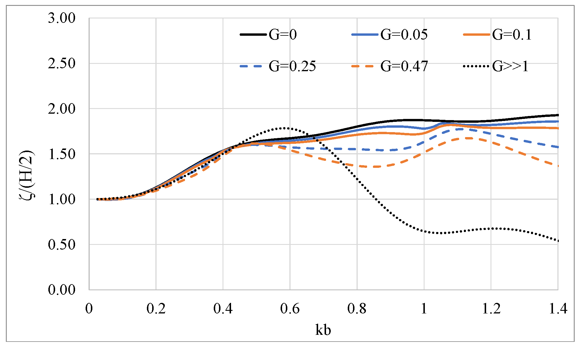
In Figure 14 the wave run-up outside the porous cylindrical surface is depicted for various examined porous coefficients. It can be seen that the presence of the outer porous surface has a constructive effect on reducing the wave run-up outside the porous body. Specifically, as increases, the wave run-up decreases. Furthermore, the resonant locations (i.e., at kb ≈ 0.4 and kb ≈ 1.025) are notable.
5. Conclusions
The present study dealt with a theoretical model for the investigation of the hydrodynamics of a porous vertical compound cylindrical body in the presence of regular waves. Within the realm of the linear wave theory, a three-dimensional theoretical solution based on the eigenfunction expansion method is developed for the determination of the velocity potential of the flow field around the cylindrical body, whereas a linear resistance law is used to connect the pressure drop across the porous shell with the normal velocity. The main conclusions drawn from the study are:
- The presence of the porous cylindrical surface reduces the hydrodynamic forces on the inner cylinder, as well as the wave run up. This could be beneficial for minimizing the environmental impact on pile-supported marine structures;
- Sloshing phenomena due to the fluid motion in the fluid volume confined between the porous surface and the inner cylinder are notable. Accordingly, sloshing phenomena create resonant peaks in the trends of the hydrodynamic loads and the wave elevations;
- In addition, resonances at specific wave numbers are encountered in the drift forces and the wave run-up. At the corresponding wave numbers, the porous surface cannot dissipate the wave energy, thus enhancing the wave impact on the porous system;
- The presence of the outer porous cylinder causes an increase on the hydrodynamic forces and added mass, which are bounded by the limiting cases G = 0 and G ≫ 1 On the other hand, the damping coefficient is not bounded by these limiting cases due to the existence of the additional porous damping, which increases the values of the total damping coefficient;
- The chosen porosity plays a key role in reducing/controlling the forces and moments on a system under consideration by dissipating the wave energy. The permeability of the outer porous surface increases with the increase of G, enhancing the wave impact on the inner cylinder. Hence, G needs to be chosen so as to have the optimum impact on the inner cylinder in addition to reducing the resonance effects.
The present theoretical analysis will be further developed in order to account for quadratic dissipation of a porous body of arbitrary shape and number of porous surfaces. Furthermore, the analysis will be also extended to account for the wave interaction phenomena among arrays of floating porous cylindrical bodies.
Author Contributions
Conceptualization, I.K.C. and S.A.M.; methodology, D.N.K.; software, S.A.M., D.N.K.; validation, D.N.K. and I.K.C.; investigation, D.N.K.; I.K.C. and S.A.M.; writing—original draft preparation, D.N.K.; writing—review and editing, I.K.C. and S.A.M.; supervision, I.K.C. and S.A.M.; project administration, I.K.C. All authors have read and agreed to the published version of the manuscript.
Funding
This research received financial support by Greek national funds through the Operational Program “Competitiveness, Entrepreneurship & Innovation” of the National Strategic Reference Framework (NSRF)—Research Funding Program: “MATISSE: Study of the appropriateness and the adequacy of modern materials for offshore fish cage—numerical and experimental investigation in realistic loading conditions”.
Conflicts of Interest
The authors declare no conflict of interest.
Nomenclature
| Wave amplitude | |
| k | Wave number |
| ω | Wave frequency |
| d | Constant water depth |
| h | Distance between the bottom of the body and the seabed |
| h1 | Distance between the bottom of the porous surface and the seabed |
| α | Radius of the porous cylindrical surface |
| b | Radius of the coaxial cylinder |
| Velocity potential around the porous body, k = I, II, III | |
| Velocity potential of the undisturbed incident regular wave | |
| Scattered velocity potential | |
| Diffraction velocity potential | |
| Radiation velocity potential, j = 1,3,5 | |
| Complex velocity amplitude of body motion in j-th direction | |
| m-th Bessel function of first kind | |
| Neumann’s symbol | |
| Principal unknowns of the diffraction and radiation problems, ℓ = D, 1, 3, 5; k= I, II, III | |
| S | Body’s impermeable wetted surface |
| Generalized normal vector | |
| μ | Dynamic viscosity |
| γ | Material constant |
| ρ | Fluid density |
| Porous coefficient | |
| τ | Opening rate of the material |
| ε | Wave slope |
| m-th order Hankel function of first kind | |
| m-th order modified Bessel function of second kind | |
| Orthonormal eigenfunctions | |
| m-th order modified Bessel function of first kind | |
| Fourier coefficients defined by the solution of the corresponding diffraction and radiation problems | |
| Horizontal exciting forces | |
| Vertical exciting forces | |
| M | Overturning moment |
| Hydrodynamic reaction forces | |
| Added mass coefficients | |
| Damping coefficients | |
| Mean drift wave forces | |
| Gravity acceleration | |
| M | Generalized mass matrix |
| First-order translations vector | |
| R | Rotational transformation matrix |
| First-order translational accelerations of body’s center of gravity | |
| Relative wave elevation | |
| Vertical distance of the body’s center of gravity from the seabed |
Appendix A
Values of the functions defined in Equation (17):
For , i.e., absence of the coaxial cylindrical body, the functions are reduced to:
Appendix B
Here is given a brief presentation of the numerical procedure that was followed to evaluate the unknown Fourier coefficients, in each fluid domain.
The condition for the continuity of the potential at the boundaries of neighboring elements (i.e., element type I and III) is expressed through Equation (12). It follows that:
After multiplying both sides of Equation (A3) with and integrating over [0,h], the following equation in a matrix notation is obtained:
In Equation (A4) are both complex vectors, the elements of which are the unknown Fourier coefficients of the I and III ring element type, whereas is a (N × M) matrix given by:
For , then:
for , then:
It should be noted that: Furthermore, the term in Equation (A4) is a complex vector, that is equal to:
Concerning the continuity of the velocity potential at the I and the II neighboring ring elements, given in Equation (10), it holds that:
After multiplying both sides of Equation (A8) with and integrating over [, d], the following equation in a matrix notation is obtained:
where
In Equation (A9), is a (N × M) matrix given by:
- for , then:
- for then:
Furthermore, in Equation (A9) is a complex vector, that is equal to:
The condition for continuity of the radial derivative of the potential at the boundaries of neighboring elements I–III and I–II is expressed through Equations (12) and (13). Furthermore, the kinematic condition on the vertical impermeable surface of the body, as described in Equation (8), must be satisfied as well. Multiplying both sides of equations with the weight function and integrating over the region of their validity, that is [0,h1] and [h1,d], respectively, and adding the resulting expressions, the following equation in a matrix form is obtained:
In Equation (A13) the term is a (N × N) square matrix given by:
Additionally, the term is a diagonal matrix with for n = 1 and for n > 1, whereas the is a (M × M) square matrix the elements of which are given by:
The term is given in Equations (A5) and (A6), whereas the term is a complex vector, the elements of which are equal to:
In Equation (A16) stands for the Kronecker’s delta function and the terms are (M × M) diagonal matrices defined by:
where , are given in Equations (A1) and (A2).
The term in Equation (A13) is a complex vector, that is equal to:
Especially on the vertical boundary the kinematic condition (Equation (8)) must be satisfied, i.e.,
The matrices of Equation (A9) are defined in Equation (A17) for whereas is a complex vector, that is equal to:
The solution of the system of Equations (A4), (A9), (A13) and (A18) yields the unknown Fourier coefficients .
References
- Sollitt, C.; Cross, R. Wave transmission through permeable breakwaters. In Proceedings of the 13th Coastal Engineering Conference, Vancouver, BC, Canada, 10–14 July 1972; pp. 1827–1846. [Google Scholar]
- Madsen, O. Wave transmission through porous structures. J. Waterw. Ports Coast. Ocean. Eng. Div. 1974, 100, 169–188. [Google Scholar]
- Solitt, C.; Cross, R. Wave Reflection and Transmission at Permeable Breakwaters; Tech. Paper 76-8; US Army Corps of Engineers, Coastal Engineering Research Center: Fort Belvoir, VA, USA, 1976. [Google Scholar]
- Sulisz, W. Wave reflection and transmission at permeable breakwaters of arbitrary cross section. Coast. Eng. 1985, 9, 371–386. [Google Scholar] [CrossRef]
- Dalrymple, R.; Losada, I.; Martin, O. Reflection and transmission from porous structures under oblique wave attack. J. Fluid Mech. 1991, 224, 625–644. [Google Scholar] [CrossRef]
- Darwiche, M.; Williams, A.; Wang, K. Wave interaction with a semi-porous cylindrical breakwater. J. Waterw. Ports Coast. Ocean. Eng. Div. 1994, 120, 382–403. [Google Scholar] [CrossRef]
- Losada, I.; Losada, M.; Martin, F. Experimental study of wave induced flow in a porous structure. Coast. Eng. 1995, 27, 77–98. [Google Scholar] [CrossRef]
- Pengzhi, L.; Karunarathna, S. Numerical study of solitary wave interaction with porous breakwaters. J. Waterw. Port. Coast. Ocean. Eng. 2007, 133, 352–363. [Google Scholar]
- Lan, Y.; Hsu, T.; Lai, J.; Chwang, C.; Ting, C. Bragg scattering of waves propagating over a series of poro-elastic submerged breakwaters. Wave Motion 2011, 48, 1–12. [Google Scholar] [CrossRef]
- Liu, Y.; Li, H.J. Wave reflection and transmission by porous breakwaters: A new analytical solution. Coast. Eng. 2013, 78, 46–52. [Google Scholar] [CrossRef]
- Pereira, E.; The, H.; Manoharan, L.; Lim, C. Design optimization of porous box-type breakwater subjected to regular waves. MATEC Web Conf. 2018, 203, 01018. [Google Scholar] [CrossRef] [Green Version]
- Chwang, A. A porous-wavemaker theory. J. Fluid Mech. 1983, 132, 395–406. [Google Scholar] [CrossRef]
- Chwang, A.; Li, W. A piston-like porous wavemaker theory. J. Eng. Math. 1983, 17, 301–313. [Google Scholar] [CrossRef]
- Chwang, A.; Dong, Z. Wave-trapping due to a porous plate. In Proceedings of the 15th ONR Symposium on Naval Hydrodynamics, Hamburg, Germany, 2–7 September 1984; pp. 407–414. [Google Scholar]
- Yu, X.; Chwang, A. Water waves above submerged porous plate. J. Eng. Mech. 1994, 120, 1270–1280. [Google Scholar] [CrossRef]
- Behera, H.; Sahoo, T. Hydroelastic analysis of gravity wave interaction with submerged horizontal flexible porous plate. J. Fluid Struct. 2015, 54, 643–660. [Google Scholar] [CrossRef]
- Mohapatra, S.C.; Sahoo, T.; Guedes Soares, C. Surface gravity wave interaction with a submerged horizontal flexible porous plate. Appl. Ocean. Res. 2018, 78, 61–74. [Google Scholar] [CrossRef]
- Zheng, S.; Meylan, M.; Zhu, G.; Greaves, D.; Iglesias, G. Hydroelastic interaction between water waves and an array of circular floating porous elastic plates. J. Fluid Mech. 2020, 900, A20. [Google Scholar] [CrossRef]
- Zheng, S.; Meylan, M.; Fan, L.; Greaves, D.; Iglesias, G. Wave scattering by a floating porous elastic plate of arbitrary shape: A semi-analytical study. J. Fluids Struct. 2020, 92, 102827. [Google Scholar] [CrossRef]
- Zheng, S.; Meylan, M.; Greaves, D.; Iglesias, G. Water-wave interaction with submerged porous elastic disks. Phys. Fluids 2020, 32, 047106. [Google Scholar] [CrossRef]
- Mohapatra, S.C.; Guedes Soares, C. Hydroelastic response of a flexible submerged porous plate for wave energy absorption. J. Mar. Sci. Eng. 2020, 8, 698. [Google Scholar] [CrossRef]
- Mohapatra, S.C.; Guedes Soares, C. Hydroelastic behavior of a submerged horizontal flexible porous structure in three-dimensions. J. Fluids Struct. 2021, 104, 103319. [Google Scholar] [CrossRef]
- Wang, K.-H.; Ren, X. Wave interaction with a concentric porous cylinder system. Ocean. Eng. 1994, 21, 343–360. [Google Scholar] [CrossRef]
- Govare, G.; Silva, R.; Maza, J. Wave kinematics around a protected cylindrical impermeable pile. Coast. Struct. 1999, 1, 151–158. [Google Scholar]
- Williams, A.; Li, W. Water wave interaction with an array of bottom-mounted surface-piercing porous cylinders. Ocean. Eng. 2000, 27, 841–866. [Google Scholar] [CrossRef]
- Williams, A.; Li, W.; Wang, K.H. Water wave interaction with a floating porous cylinder. Ocean. Eng. 2000, 27, 1–28. [Google Scholar] [CrossRef]
- Teng, B.; Zhao, M.; Li, Y.C. Wave diffraction from a cylinder with porous upper wall and an inner column. ACTA Oceanol. Sin. 2001, 23, 133–142. [Google Scholar]
- Sankarbabu, K.; Sannasiraj, S.A.; Sundar, V. Interaction of regular waves with a group of dual porous circular cylinders. Appl. Ocean. Res. 2007, 29, 180–190. [Google Scholar] [CrossRef]
- Vijayalakshmi, K.; Sundaravadivelu, R.; Murali, K.; Neelamani, S. Hydrodynamics of a concentric twin perforated circular cylinder system. J. Waterw. Port. Coast. Ocean. Eng. 2008, 134, 166–177. [Google Scholar] [CrossRef]
- Bao, W.; Kinoshita, T.; Zhao, F. Wave forces on a semi-submerged porous circular cylinder. Proc. Inst. Mech. Eng. Part M J. Eng. Marit. Environ. 2009, 223, 349–360. [Google Scholar] [CrossRef]
- Park, M.S.; Koo, W.; Choi, Y. Hydrodynamic interaction with an array of porous circular cylinders. Int. J. Nav. Archit. Ocean. Eng. 2010, 2, 146–154. [Google Scholar] [CrossRef] [Green Version]
- Zhao, F.; Bao, W.-G.; Kinoshita, T.; Itakura, H. Theoretical and experimental study on a porous cylinder floating in waves. ASME J. Offshore Mech. Arct. Eng. 2011, 133, 011301. [Google Scholar] [CrossRef]
- Zhao, F.; Kinoshita, T.; Bao, W.-G.; Huang, L.-Y.; Liang, Z.; Wan, R. Interaction between waves and an array of floating porous circular cylinders. China Ocean. Eng. 2012, 26, 397–412. [Google Scholar] [CrossRef]
- Park, M.S.; Koo, W. Mathematical modeling of partial-porous circular cylinders with water waves. Hindawio Publishing Corporation. Math. Probl. Eng. 2015, 2015, 903748. [Google Scholar] [CrossRef]
- Ning, D.Z.; Zhao, X.-L.; Teng, B.; Johanning, L. Wave diffraction from a truncated cylinder with an upper porous sidewall and an inner column. Ocean. Eng. 2017, 130, 471–481. [Google Scholar] [CrossRef] [Green Version]
- Dokken, J.; Grue, J.; Karstensen, P. Wave analysis of porous geometry with linear resistance law. J. Mar. Sci. Appl. 2017, 16, 1–10. [Google Scholar] [CrossRef] [Green Version]
- Dokken, J.; Grue, J.; Karstensen, P. Wave forces on porous geometries with linear and quadratic pressure-velocity relations. In Proceedings of the 32nd International Workshop on Water Waves and Floating Bodies, IWWWFB, Dalin, China, 23–26 April 2017. [Google Scholar]
- Cong, P.; Bai, W.; Teng, B. Analytical modeling of water wave interaction with a bottom-mounted surface-piercing porous cylinder in front of a vertical wall. J. Fluids Struct. 2019, 88, 292–314. [Google Scholar] [CrossRef]
- Sankar, A.; Bora, S.N. Hydrodynamic forces due to water wave interaction with a bottom-mounted surface-piercing compound porous cylinder. Ocean. Eng. 2019, 171, 59–70. [Google Scholar] [CrossRef]
- Sankar, A.; Bora, S.N. Hydrodynamic coefficients for a floating semi-porous compound cylinder in finite ocean depth. Mar. Syst. Ocean. Technol. 2020, 15, 270–285. [Google Scholar] [CrossRef]
- Sankar, A.; Bora, S.N. Hydrodynamic forces and moments due to interaction of linear water waves with truncated partial-porous cylinders in finite depth. J. Fluids Struct. 2020, 94, 102898. [Google Scholar] [CrossRef]
- Mackay, E.; Liang, H.; Johanning, L. A BEM model for wave forces on structures with thin porous elements. J. Fluids Struct. 2021, 102, 103246. [Google Scholar] [CrossRef]
- Liang, H.; Housseine, C.; Chen, X.; Shao, Y. Efficient methods free of irregular frequencies in wave and solid/porous structure interactions. J. Fluids Struct. 2020, 98, 103130. [Google Scholar] [CrossRef]
- Li, L.; Fu, S.; Xu, Y.; Wang, J.; Yang, J. Dynamic responses of floating fish cage in waves and current. Ocean. Eng. 2013, 72, 297–303. [Google Scholar] [CrossRef]
- Mandal, S.; Sahoo, T. Wave interaction with floating flexible circular cage system. In Proceedings of the 11th International Conference on Hydrodynamics (ICHD 2014), Singapore, 19–24 October 2018. [Google Scholar]
- Su, W.; Zhan, J.M.; Huang, H. Wave interactions with a porous and flexible cylindrical fish cage. Procedia Eng. 2015, 126, 254–259. [Google Scholar] [CrossRef] [Green Version]
- Shen, Y.; Greco, M.; Faltinsen, O.M.; Nygaard, I. Numerical and experimental investigations on mooring loads of a marine fish farm in waves and current. J. Fluid Struct. 2018, 79, 115–136. [Google Scholar] [CrossRef]
- Faltinsen, O.M.; Shen, Y. Wave and current effects on floating fish farms. J. Mar. Sci. Appl. 2018, 17, 284–296. [Google Scholar] [CrossRef]
- Liu, Z.; Mohapatra, S.C.; Guedes Soares, C. Finite element analysis of the effect of currents on the dynamics of a moored flexible cylindrical net cage. J. Mar. Sci. Eng. 2021, 9, 159. [Google Scholar] [CrossRef]
- Chu, Y.I.; Wang, C.M. Combined Spar and partially porous wall fish cage for offshore site. In Lecture Notes in Civil Engineering; Wang, C.M., Dao, V., Eds.; EASEC16; Springer: Singapore, 2019; Volume 101. [Google Scholar] [CrossRef]
- Zitti, G.; Novelli, N.; Brocchini, M. Preliminary results on the dynamics of a pile-moored fish cage with elastic net in currents and waves. J. Mar. Sci. Eng. 2021, 9, 14. [Google Scholar] [CrossRef]
- Pinkster, J.A.; Oortmerssen, G.V. Computation of the first and second order wave forces on oscillating bodies in regular waves. In Proceedings of the 2nd International Conference on Numerical Ship Hydrodynamics, Berkeley, CA, USA, 19–21 September 1977. [Google Scholar]
- Kokkinowrachos, K.; Mavrakos, S.A.; Asorakos, S. Behaviour of vertical bodies of revolution in waves. Ocean. Eng. 1986, 13, 502–538. [Google Scholar] [CrossRef]
- Yu, X.P. Diffraction of water waves by porous breakwaters. J. Waterw. Port. Coast. Ocean. Eng. 1995, 121, 275–282. [Google Scholar] [CrossRef]
- Mavrakos, S.A.; Bardis, L. Hydrodynamic analysis of floating solar ponds. Soc. Nav. Archit. Mar. Eng. 1986, 24, 1–12. [Google Scholar]
- Mavrakos, S.A. Hydrodynamic characteristics of floating toroidal bodies. Ocean. Eng. 1997, 24, 381–399. [Google Scholar] [CrossRef]
- Molin, B. On second-order motion and vertical drift forces for three-dimensional bodies in regular waves. In Proceedings of the International Workshop on Ship and Platform Motion, Berkeley, CA, USA, 26–28 October 1983; pp. 344–357. [Google Scholar]
- Standing, R.G.; Dacunha, N.M.C. Slowly-varying and mean second-order wave forces on ships and offshore structures. In Proceedings of the 14th Symposium on Naval Hydrodynamics, Ann Arbor, MI, USA, 23–27 August 1982; pp. 279–318. [Google Scholar]
- Papanikolaou, A.; Zaraphonitis, G. On the improved method for the evaluation of second-order motions and loads on 3D floating bodies in waves. J. Schiffstechnik 1987, 34, 170–211. [Google Scholar]
- Mavrakos, S.A. User’s Manual for the Computer Code HAMVAB; Laboratory for Floating Bodies and Mooring Systems, National Technical University of Athens: Athens, Greece, 2001. [Google Scholar]
- Zhao, F.; Kinoshita, T.; Bao, W.-G.; Wan, R.; Liang, Z.; Huang, L. Hydrodynamics identities and wave-drift force of a porous body. Appl. Ocean. Res. 2011, 33, 169–177. [Google Scholar] [CrossRef]
- Cong, P.; Liu, Y. Local enhancement of the mean drift wave forces on a vertical column shielded by an exterior thin porous shell. J. Mar. Sci. Eng. 2020, 8, 349. [Google Scholar] [CrossRef]
- Silverman, S.; Abramson, H.N. The Dynamic Behavior of Liquids in Moving Containers; NASA SP-106; NASA: Washington, DC, USA, 1966.
- Mavrakos, S.A. Hydrodynamic coefficients for a thick bottomless cylindrical body floating in water of finite depth. Ocean. Eng. 1988, 15, 213–224. [Google Scholar] [CrossRef]
Figure 2.
Comparison of the present method results against those from Zhao et al. [32], concerning the exciting forces and moments on a porous cylinder.
Figure 2.
Comparison of the present method results against those from Zhao et al. [32], concerning the exciting forces and moments on a porous cylinder.
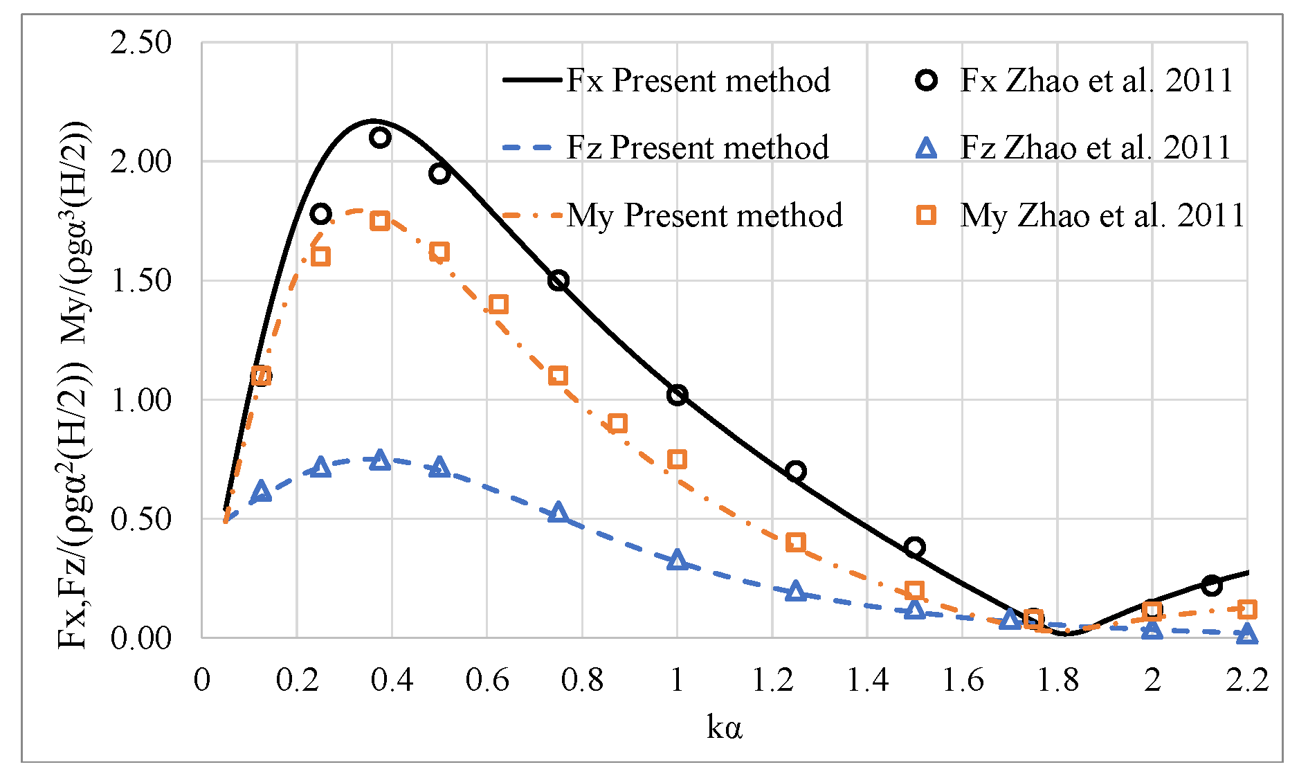
Figure 3.
Comparison of the present method results against those due to Zhao et al. [32], concerning the hydrodynamic coefficients of a porous cylinder: (a) hydrodynamic added mass in surge and heave; (b) hydrodynamic damping coefficients in surge and heave.
Figure 3.
Comparison of the present method results against those due to Zhao et al. [32], concerning the hydrodynamic coefficients of a porous cylinder: (a) hydrodynamic added mass in surge and heave; (b) hydrodynamic damping coefficients in surge and heave.
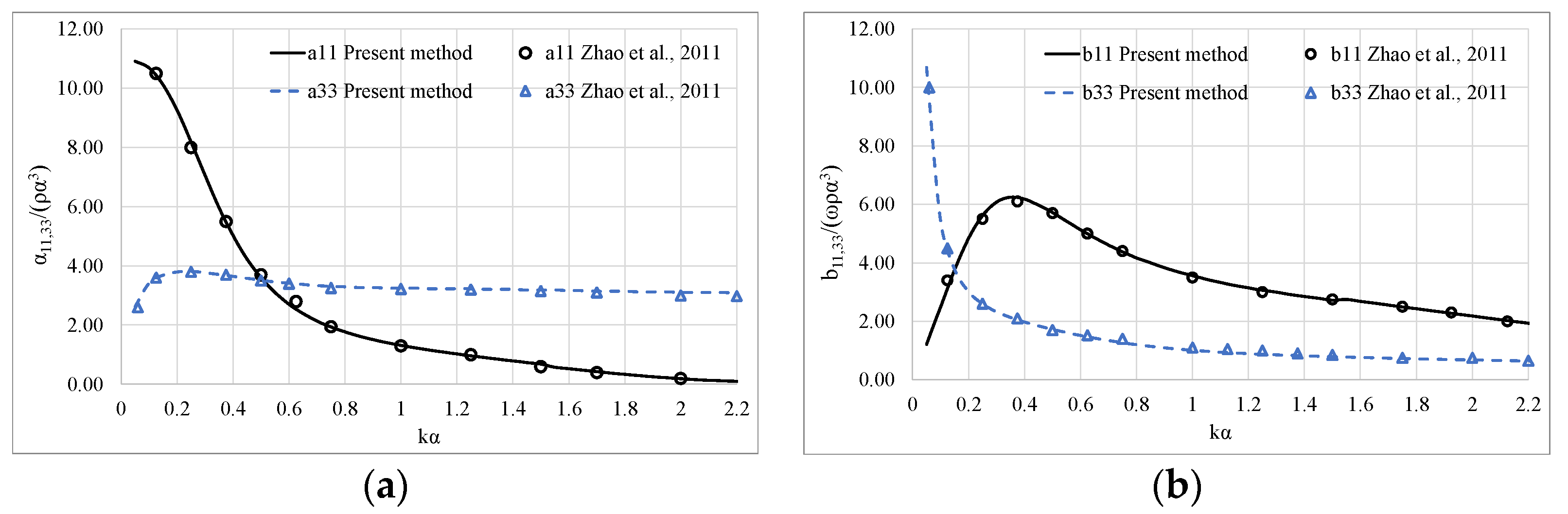
Figure 4.
Comparison of the present method results against those from Zhao et al. [61], concerning the horizontal drift forces on a porous cylinder.
Figure 4.
Comparison of the present method results against those from Zhao et al. [61], concerning the horizontal drift forces on a porous cylinder.
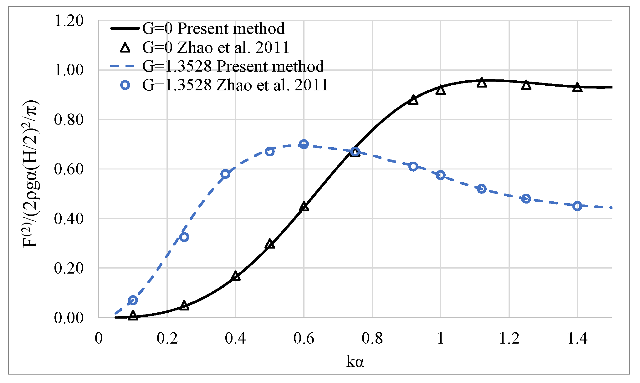
Figure 5.
Effect of the porous coefficient G on the horizontal exciting wave loads on a porous bottom-mounted cylindrical body: (a) horizontal exciting forces; (b) horizontal exciting moments.
Figure 5.
Effect of the porous coefficient G on the horizontal exciting wave loads on a porous bottom-mounted cylindrical body: (a) horizontal exciting forces; (b) horizontal exciting moments.

Figure 6.
Effect of the porous coefficient G on the mean drift forces on a porous bottom-mounted cylindrical body. The results are compared against those reported in [62].
Figure 6.
Effect of the porous coefficient G on the mean drift forces on a porous bottom-mounted cylindrical body. The results are compared against those reported in [62].
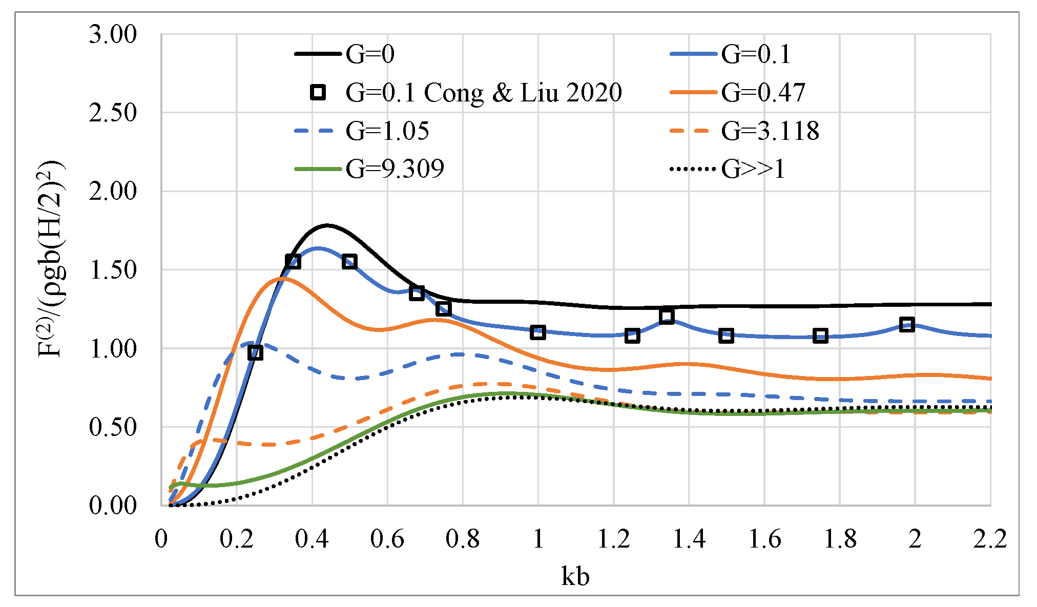
Figure 7.
Effect of the porous coefficient G on the wave run up of the porous cylindrical system.
Figure 8.
Effect of the porous coefficient G on the horizontal exciting wave loads on a porous bottom-mounted compound cylindrical body: (a) horizontal exciting forces; (b) horizontal exciting moments.
Figure 8.
Effect of the porous coefficient G on the horizontal exciting wave loads on a porous bottom-mounted compound cylindrical body: (a) horizontal exciting forces; (b) horizontal exciting moments.
Figure 9.
Effect of the porous coefficient G on the mean drift forces on a porous bottom-mounted compound cylindrical body.
Figure 9.
Effect of the porous coefficient G on the mean drift forces on a porous bottom-mounted compound cylindrical body.
Figure 10.
Effect of the porous coefficient G on the wave run up of a porous bottom-mounted compound cylindrical body.
Figure 10.
Effect of the porous coefficient G on the wave run up of a porous bottom-mounted compound cylindrical body.
Figure 11.
Effect of the porous coefficient G on the horizontal exciting wave loads and overturning moments on a floating porous compound cylindrical body: (a) horizontal exciting forces; (b) overturning moments.
Figure 11.
Effect of the porous coefficient G on the horizontal exciting wave loads and overturning moments on a floating porous compound cylindrical body: (a) horizontal exciting forces; (b) overturning moments.
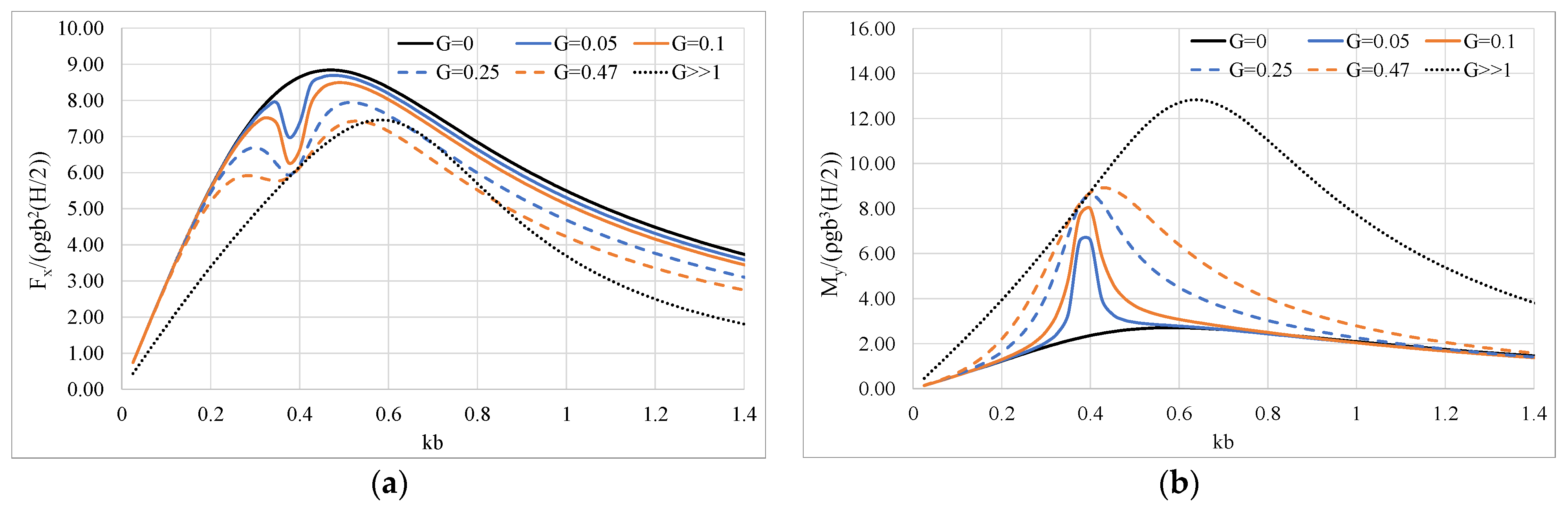
Figure 12.
Effect of the porous coefficient G on the horizontal hydrodynamic coefficients of a floating porous compound cylindrical body: (a) added mass; (b) damping coefficient.
Figure 12.
Effect of the porous coefficient G on the horizontal hydrodynamic coefficients of a floating porous compound cylindrical body: (a) added mass; (b) damping coefficient.
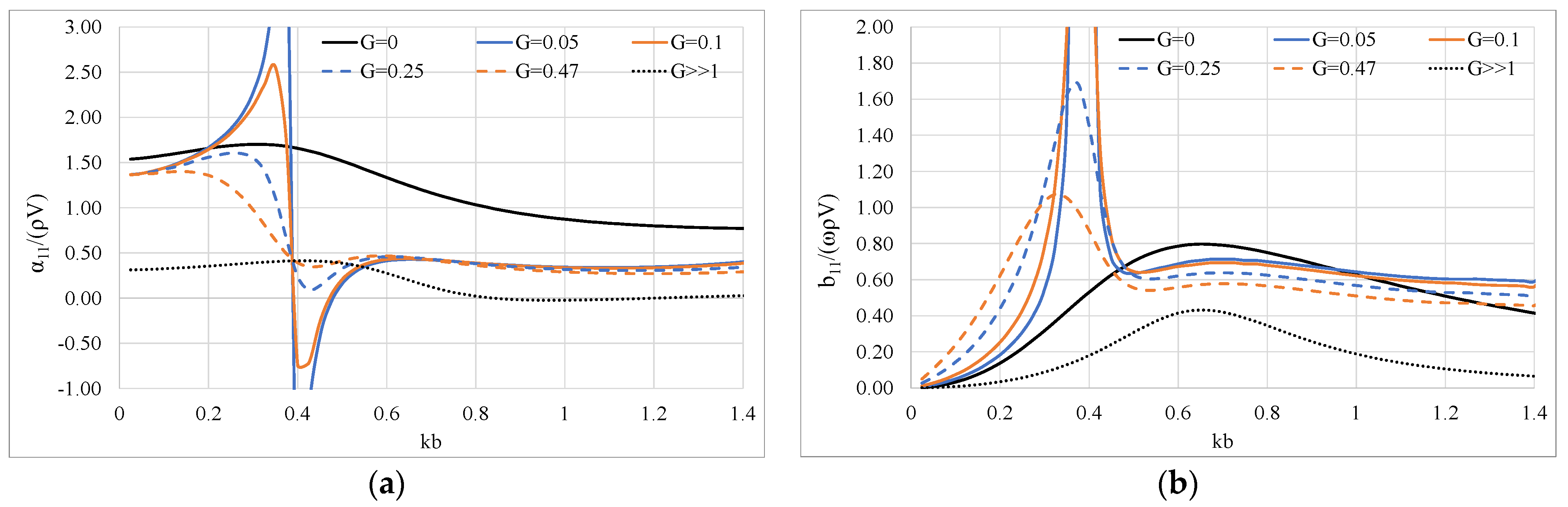
Figure 13.
Effect of the porous coefficient G on the mean drift forces on a floating porous compound cylindrical body.
Figure 13.
Effect of the porous coefficient G on the mean drift forces on a floating porous compound cylindrical body.

Figure 14.
Effect of the porous coefficient G on the wave run up on a floating porous compound cylindrical body.
Figure 14.
Effect of the porous coefficient G on the wave run up on a floating porous compound cylindrical body.

Table 1.
Porous coefficient G and the corresponding opening rate τ of the porous surface for ε = 0.05, based on Equation (11).
Table 1.
Porous coefficient G and the corresponding opening rate τ of the porous surface for ε = 0.05, based on Equation (11).
| τ | 0.037 | 0.08 | 0.12 | 0.22 | 0.41 | 0.60 |
| G | 0.100 | 0.468 | 1.015 | 3.118 | 9.309 | 17.482 |
Publisher’s Note: MDPI stays neutral with regard to jurisdictional claims in published maps and institutional affiliations. |
© 2021 by the authors. Licensee MDPI, Basel, Switzerland. This article is an open access article distributed under the terms and conditions of the Creative Commons Attribution (CC BY) license (https://creativecommons.org/licenses/by/4.0/).
Share and Cite
MDPI and ACS Style
Konispoliatis, D.N.; Chatjigeorgiou, I.K.; Mavrakos, S.A. Theoretical Hydrodynamic Analysis of a Surface-Piercing Porous Cylindrical Body. Fluids 2021, 6, 320. https://doi.org/10.3390/fluids6090320
AMA Style
Konispoliatis DN, Chatjigeorgiou IK, Mavrakos SA. Theoretical Hydrodynamic Analysis of a Surface-Piercing Porous Cylindrical Body. Fluids. 2021; 6(9):320. https://doi.org/10.3390/fluids6090320
Chicago/Turabian StyleKonispoliatis, Dimitrios N., Ioannis K. Chatjigeorgiou, and Spyridon A. Mavrakos. 2021. "Theoretical Hydrodynamic Analysis of a Surface-Piercing Porous Cylindrical Body" Fluids 6, no. 9: 320. https://doi.org/10.3390/fluids6090320