
Microfluidic Invasion Chemotaxis Platform for 3D Neurovascular Co-Culture
by
 ,
,
Emel Sokullu
1,2,*, 
Zeynel Levent Cücük
3,
Misagh Rezapour Sarabi
4,
Mehmet Tugrul Birtek
4,
Hesam Saghaei Bagheri
1,2 and
Savas Tasoglu
2,4,5,6,* 1
Koç University Translational Medicine Research Center (KUTTAM), Koç University, Sarıyer, 34450 Istanbul, Türkiye
2
School of Medicine, Biophysics Department, Koç University, Sarıyer, 34450 Istanbul, Türkiye
3
Graduate School of Nanoscience and Nanotechnology, Department of Natural and Applied Sciences, Izmir Katip Celebi University, 35000 Izmir, Türkiye
4
Mechanical Engineering Department, School of Engineering, Koç University, Sarıyer, 34450 Istanbul, Türkiye
5
Physical Intelligence Department, Max Planck Institute for Intelligent Systems, 70569 Stuttgart, Germany
6
Koc University Is Bank Artificial Intelligence Lab (KUIS AI Lab), Koç University, Sariyer, 34450 Istanbul, Türkiye
*
Authors to whom correspondence should be addressed.
Fluids 2022, 7(7), 238; https://doi.org/10.3390/fluids7070238
Submission received: 13 June 2022
/
Revised: 6 July 2022
/
Accepted: 11 July 2022
/
Published: 13 July 2022
Abstract
:Advances in microfabrication and biomaterials have enabled the development of microfluidic chips for studying tissue and organ models. While these platforms have been developed primarily for modeling human diseases, they are also used to uncover cellular and molecular mechanisms through in vitro studies, especially in the neurovascular system, where physiological mechanisms and three-dimensional (3D) architecture are difficult to reconstruct via conventional assays. An extracellular matrix (ECM) model with a stable structure possessing the ability to mimic the natural extracellular environment of the cell efficiently is useful for tissue engineering applications. Conventionally used techniques for this purpose, for example, Matrigels, have drawbacks of owning complex fabrication procedures, in some cases not efficient enough in terms of functionality and expenses. Here, we proposed a fabrication protocol for a GelMA hydrogel, which has shown structural stability and the ability to imitate the natural environment of the cell accurately, inside a microfluidic chip utilizing co-culturing of two human cell lines. The chemical composition of the synthesized GelMA was identified by Fourier transform infrared spectrophotometry (FTIR), its surface morphology was observed by field emission electron microscopy (FESEM), and the structural properties were analyzed by atomic force microscopy (AFM). The swelling behavior of the hydrogel in the microfluidic chip was imaged, and its porosity was examined for 72 h by tracking cell localization using immunofluorescence. GelMA exhibited the desired biomechanical properties, and the viability of cells in both platforms was more than 80% for seven days. Furthermore, GelMA was a viable platform for 3D cell culture studies and was structurally stable over long periods, even when prepared by photopolymerization in a microfluidic platform. This work demonstrated a viable strategy to conduct co-culturing experiments as well as modeling invasion and migration events. This microfluidic assay may have application in drug delivery and dosage optimization studies.
1. Introduction
The development of biomaterials and microfabrication methods have enabled the creation of microfluidic tissue and organ models to overcome the challenges of conventional methods of animal tests or cell culture systems, including the high cost, complexity, ethical issues, and inaccuracy in human tissue models [1,2]. On the other hand, the required biocompatibility in traditional setups is often achieved through multiple surface treatments or the addition of coatings. Advances in tissue engineering and microfabrication methods enabled the development of micro physiological systems (MPS) recapitulating human organ functions [3,4,5,6,7,8,9]. These systems have been mainly designed for modeling human diseases such as cancer, autoimmune diseases, infectious diseases, and neurodegenerative diseases [10,11]. These include amyotrophic lateral sclerosis (ALS), spinal muscular atrophy (SMA), Alzheimer’s disease (AD), as well as cardiovascular diseases, and preclinical drug development [12,13,14]. In addition, they are increasingly being used to reveal cellular and molecular mechanisms [15,16]. Microfluidic setups containing patient-derived cells allow for studying extracellular matrix (ECM) at cellular scales [17,18]. In addition, many inherited diseases involve multiple genetic mutations, requiring various animal models for a single disease [19,20,21,22]. Microfluidics enables the production of systems populated with human cells that recapitulate some aspects of organ functions and can be used to study important molecular or cellular events in a physiologically-relevant construct for exploring the causes of acute or chronic diseases [23]. These microfluidic organ-on-chip (OOC) models are particularly relevant to the study of diseases, where functional performance, for instance, resistance to mass transport, fluid displacement, and mechanical force, can be well characterized [17,24]. Another example in this regard is the detection of human placental pathologies [25]. Based on microfluidics technology, the development of a 3D placenta-on-a-chip model was investigated for the in vitro simulation of the placental interface between maternal and fetal blood [26]. A vital feature of such models is the control over microenvironmental parameters. These include the content and mechanical properties of the extracellular matrix, the incorporation of stromal and supporting cell types, and the recapitulation of physiological hemodynamics and tissue architecture. Organ-on-a-chip systems present a suitable platform for isolating factors associated with microfluidic cardiovascular models with the disease by combining cellular and molecular techniques such as stem cell technology, methods of isolating and maintaining primary cells, gene editing tools, delivery of bioactive and biocompatible components such as drugs, growth factors (GFs), biomolecules, and cells to their target destinations, or sampling bioagents [27,28,29,30].
The recent emergence of biodegradable materials offers an opportunity to transform health technologies by enabling sensors that naturally degrade after usage [31,32,33]. The eco-friendly systems developed from degradable materials could also help mitigate significant environmental problems by reducing electronic or medical waste generated, thus also reducing the carbon footprint [34,35]. With the integration of tissue engineering methods, biodegradable devices were introduced to biomedical applications [36,37]. There are many types of biodegradable devices, such as plant-based polysaccharides (e.g., cellulose, alginate, dextran) and animal-derived polymers (e.g., collagen, silk, chitosan) [32,38,39] and polyaniline-grafted gelatin hydrogels, which can be rapidly produced and simultaneously integrated into bio-platforms [40,41,42,43]. Several strategies have been developed to fabricate scaffolds for in vitro tissue engineering applications, including electrospinning, 3D printing, and molding techniques [9,44,45,46]. Hydrogels can change their chemo physical properties in response to physical stimuli, such as pH, temperature, and changes in salt concentration that allow for mimicking the permeability of the ECM for optimal transport of oxygen, nutrients, and waste products [47,48]. Since hydrogels possess cellular biocompatibility, they have many applications as cellular scaffolds or vehicles for drug delivery. Hydrogels for cell encapsulation can be synthesized via cross-linking of polymers, using photopolymerization, usually carried out using a photoinitiator and irradiation at the optimal wavelength for cell survival and optimal gel structure. Photopolymerization has faster cure rates compared to conventional room-temperature polymerization techniques [49]. In addition, using light instead of thermal polymerization offers advantages such as high reaction rates, spatial control of polymerization, low energy consumption, and chemical versatility [50,51]. In addition, the preparation of polymers in situ is advantageous because it is easier to form complex shapes containing tissue structures. In contrast, a challenge for the polymerization method is the difficulty of setting biologically-optimal conditions for the formation of polymers [52,53,54,55,56]. Biological structures require specific properties under certain situations, such as temperature, pH, and minimal toxicity [57,58,59,60]. However, since photopolymerization conditions are milder than conventional polymerization techniques, these challenges can be overcome [61,62,63].
In this study, we developed a microfluidic setup for creating 3D cell culture models. We presented a protocol for gelatin methacryloyl (GelMA) hydrogel fabrication inside the microfluidic chip along with embedded co-culturing of two human cell lines (HUVEC and SH-SHY5Y; Nomenclature offered in Table 1). GelMA was fabricated in the microfluidic setup using photopolymerization and investigated for its effects on cellular viability. The transparent surface of the polydimethylsiloxane (PDMS) in the microfluidic chip allowed the photoinitiation process through a light source. First, GelMA was synthesized, and its properties, such as surface morphology and structure, were identified by Fourier transform infrared spectrophotometry (FTIR), field emission electron microscopy (FESEM), and atomic force microscopy (AFM). In addition, the swelling behavior of the GelMA in the microfluidic chip was imaged, as swelling is one of the main factors for a cell-encapsulated hydrogel for continuous nutrition to stay viable for longer durations. GelMA exhibited the desired biomechanical properties and a great viability of cells at more than 80% for seven days. In addition, a migration experiment was also performed on the setup. The results of this study demonstrated a viable strategy to conduct co-culturing experiments as well as modeling invasion and migration events. This setup can be used in experimental studies on drug delivery and drug dosage optimization in a wide range of diseases.
2. Materials and Methods
2.1. Materials
Invasion Chemotaxis Chip (IC-Chip, Initiocell, İzmir, Türkiye) (Figure 1A) is made of biocompatible polydimethylsiloxane (PDMS), consisting of three channels, one at the bottom and one at the top, with the same size and volume, and a middle channel that has three intersection points with each side channel. IC-Chip is gas-permeable to ensure the exchange of CO2 and O2 gases. The base of the chip is a thin microscope slide, allowing the direct observation of the biological sample with temporal and spatial resolution by using optical, fluorescent, and confocal microscopes [64,65,66,67,68]. The specifications of the IC-Chip are organized in Table 2. An IC-Chip was used in the setup of this study (Figure 1B). Spot UV Curing System (OmniCure S2000, Excelitas Technologies, Waltham, MA, USA), CO2 Incubator, Centrifuge, Multiskan FC Microplate Photometer (Thermo Fisher Scientific, Waltham, MA, USA), water bath (Müve NB9, Henderson Biomedical, London, United Kingdom), SEM (Zeiss GeminiSEM 500, Carl Zeiss AG, Oberkochen, Germany), and a microscope were the main equipment used in this work. The UV Curing System (30 W/cm2, 320–500 nm), consisting of a 200-Watt UV lamp, a probe, and a probe holder, was used to initiate the polymerization process to create the hydrogel that encapsulated the cells inside of its 3D structure.
2.2. Methods
Firstly, GelMA was synthesized, followed by characterization. Second, the cells were encapsulated inside the hydrogel. Then, viability tests of the encapsulated cells in the 3D matrix were performed. Immunostaining of neuroblastoma and endothelial cells were performed. The cell encapsulation resulted in the building of the 3D hydrogel structure inside the chip. Then, endothelial cells were loaded inside channels. Fluorescence imaging of the cells was performed, followed by viability tests inside the chip.
2.2.1. GelMA Synthesis
Gelatin methacryloyl (GelMA) is one of the most promising hydrogels for 3D cell culture research due to its high biocompatibility, low cost, and degradability. GelMA can be synthesized by conducting a reaction between gelatin and methacrylic anhydride (MAA), followed by modifying lysine and hydroxyl residues with methacrylamide. The gelatin molecule protects its stability as a biomaterial after derivatization. Thus, GelMA as a hydrogel can provide a biocompatible environment that promotes cell growth, adhesion, and proliferation. The modification process of methacryloyl allows GelMA to polymerize with UV light using a photoinitiator. This creates a methacryoyl backbone with covalent crosslinking, causing thermal and mechanical stability and negates the major drawbacks of conventional gelatins [69]. The mechanical properties of GelMA can be tuned, increasing its surface adhesion or altering its pore sizes, which are important factors for cell adhesion and viability [70]. To synthesize GelMA, gelatin was added to Dulbecco’s phosphate buffer saline (DPBS) solution (Biological Industries, Kibbutz Beit-Haemek, Israel) (100 mL, 10% w/v). Afterwards, the solution was dissolved at 60 °C using a magnetic stirrer. After the solution was dissolved, MAA (8%, w/v) was added at a rate of 1 mL/min. The solution was stirred at 50 °C for 3 h. The solution was diluted five times more, adding more DPBS afterwards to stop the reaction. As the reaction resulted in salts and other unwanted compounds, the solution was dialyzed for 7 days. After the dialysis, the solution was lyophilized and stored at −80 °C in the dark.
2.2.2. Surface Coating of Coverslips
To increase the surface adhesion of the glass and enable more structural stability in the gel, the surface of the coverslips was coated with 3-(trimethoxysilyl) propyl methacrylate (TMSPMA) (Sigma Aldrich, St. Louis, MO, USA). Then, a 10% NaOH (Merck, Darmstadt, Germany) solution was applied to the coverslips for 1 h. After washing with distilled water, nitrogen gas was applied to dry the coverslips. Then the coverslips were dipped into TMSPMA at 80 °C for 12 h. The coverslips were cleaned with ethanol and dried using nitrogen gas. The treated coverslips were used within 15 days after coating.
2.2.3. Field Emission Scanning Electron Microscopy Imaging of GelMA
Field emission scanning electron microscopy (FESEM) was used to image the surface morphology of the GelMA. The lyophilized GelMA was coated with palladium nanoparticles, and its surface morphology was imaged using a Zeiss Sigma 500 VP FESEM at the Izmir Biomedicine and Genome Center (IBG).
2.2.4. Preparation of the Pre-Polymer Solution
To initiate photocrosslinking, the photoinitiator Irgacure D-2959 (2-hydroxy-4′-(2-hydroxy ethoxy)-2-methyl propiophenone) was added to 1 mL of DPBS (1%, w/v) and dissolved at 80 °C in a thermo shaker. This solution was added to the GelMA (0.5%, w/v). To completely dissolve the GelMA, the solution was incubated at 80 °C for 60 min.
2.2.5. Preparation of Cells
Human umbilical vein endothelial cell (HUVEC) and neuroblastoma cell (SH-SY5Y) lines were used. The cells, which were stored in liquid nitrogen, were thawed in passages 19 and 17, respectively, in a water bath at 37 °C. The medium was prepared using Dulbecco’s Modified Eagle Medium (Gibco), 10% Fetal Bovine serum (Gibco), 1% Penicillin Streptomycin (Gibco), 1% L-Glutamine (Gibco), and 1% Sodium Pyruvate (Gibco). The cells were seeded in T75 cell culture flasks and incubated at 95% humidity, 5% CO2, and 37 °C. The cells were sub-cultured after the prior viability tests.
2.2.6. UV Curing of GelMA and Cell Seeding Inside Microfluidic Chip
A UV light spot-curing source was used to polymerize the GelMA solution. The SH-SY5Y cells were added to the solution and injected inside the middle channel of the microfluidic chip (Figure 1C(i)). Then UV light was applied (Figure 1C(ii), Table 3). The top channel of the microfluidic chip was filled with HUVEC along with the medium prepared at the cell preparation phase. The bottom channel was filled with medium without any cells (Figure 1C(iii)). After filling the channels, the chip was placed inside of a staining jar and incubated for 20–30 min with the bottom channel at the top (Figure 1C(iv)) to accelerate the medium flow through the middle channel. The chip was rotated upside down (Figure 1C(v)) to promote cell movement towards the gel. The staining jar was filled with distilled water (4 mL) to keep the interior of the staining jar humid. The cell culture medium was renewed on a daily basis.
2.2.7. Preparation of GelMA for Cell Viability Analysis
Three cell types, HUVEC, SH-SHY5Y, and co-cultured HUVEC and SH-SHY5Y cells, were encapsulated in GelMA inside well plates three times. For this process, TMSPMA-coated coverslips were firstly placed inside of the well plates prior to polymerization to increase surface adhesion. After placing the coverslip, the cells and the pre-polymer solution were applied onto the surface of the coverslips. The same UV parameters (Table 3) were applied for photopolymerization. This step was repeated 3 times for each cell type, for days 0, 1, 4, and 7, making 36 cells encapsulated GelMA hydrogels in total.
2.2.8. Cell Viability Assay
The viability of the cell-encapsulated GelMA structures was measured using an alamarBlue viability assay (ThermoFisher Scientific, Waltham, MA, USA). HUVEC, SH-SHY5Y, and the co-cultured HUVEC/SH-SHY5Y encapsulated GelMA hydrogels were scraped from the well plates using a cell scraper and placed in a 96-well microplate one by one. This process was repeated for days 0, 1, 4, and 7, respectively, to measure the viability values for those durations. After the cell-encapsulated hydrogel structures were seeded into the microplates, cell medium (90 μL) was added to each well. The medium was changed every day. Five hours prior to achieving the viability results, the cell media in each plate were refreshed, and alamarBlue (10 μL) was added to the plates. After 5 h, the viability results were measured using a microplate reader at an absorbance value of 595 nm.
2.2.9. Atomic Force Microscopy Analysis of GelMA
The surface topography of the lyophilized GelMA hydrogels was investigated by using Atomic Force Microscopy (AFM) (Easyscan 2, Nanosurf AG, Liestal, Switzerland) via Nanosurf Easyscan 2 software. The scanning procedure was operated using the tapping mode using a silicon cantilever probe Tap190Al-G (Buged Sensors, Sofia, Bulgaria) with the parameters of a force constant equal to 48 N m−1 and a resonance frequency of 65 kHz.
2.2.10. Viability Imaging of Encapsulated Cells Inside the Microfluidic Chip
Calcein AM and Propidium Iodide were used to locate the dead and alive cells inside the hydrogel. To analyze the viability on days 0, 1, 4, and 7, HUVEC and SH-SHY5Y cells were co-cultured and encapsulated inside the GelMA hydrogel in the middle channel of the chip. Both the top and bottom channels were filled with the medium with serum and incubated at 37 °C, 5% CO2, and 95% humidity. The media were refreshed every day. Prior to imaging, the media in both the top and bottom channels were removed and replaced with calcein AM and propidium iodide, respectively. Unlike the conventional protocols, both calcein AM and propidium iodide were diluted to 5 μM, a higher-than-usual ratio, as a higher brightness was observed with this dilution rate. As the gravitational force increased, the amount of liquid passing through the permeable surface of the 3D matrix from the top channel when the chip was positioned horizontally inside of the staining jar also increased; the effect of gravitational force should be minimized to distribute calcein AM and propidium iodide homogenously. After both channels were loaded with calcein AM and propidium iodide, the positions of the top and bottom channels were swapped horizontally by rotating the chip 180° every 15 min (Figure 1C(iv,v)). This process was repeated four times for a total of 1 h. Fluorescence imaging was performed using an Olympus BX51 fluorescence microscope. The images were taken from the center of the middle channel to obtain the results from the most equally distributed region of calcein AM and propidium iodide. Figure 1D shows the overall distribution of the calcein AM/propidium iodide-marked cells in the channels.
2.2.11. Swelling Test
It is vital for a hydrogel to have an ideal swelling consistency since the encapsulated cells need continuous nutrition to stay viable for longer durations. Compared to GelMA inside a microfluidic chip, GelMA on conventional platforms, such as Petri dishes, are able to swell the medium faster as they have a larger surface area in contact with the medium and other nutrients. Thus, the confirmation of successful swelling in both the top and bottom channels and efficient diffusion overnight is important. Trypan blue was used to observe the permeability of the GelMA inside the microfluidic chip. A cell-encapsulated GelMA was built inside of the middle channel of the microfluidic chip, and both the top and bottom channels were filled with medium, and the chip was incubated at 37 °C, 5% CO2, and 95% humidity. The media were refreshed on a daily basis. On days 1 and 7, the media in both channels were removed and replaced with trypan blue and left to incubate overnight.
2.2.12. Finite-Difference Simulation
The transport of trypan blue across the chip was modeled and simulated using the Finite Elements Method. The concentration gradient was calculated with conservation of diffusion where the diffusive flux, , was calculated with Fick’s first law of diffusion [71]:
where is the diffusion coefficient and is the concentration. The fluid diffusion coefficient for trypan blue was calculated with the Stokes–Einstein equation [72]:
where is the Boltzmann constant, is temperature, is the dynamic viscosity of the solute, and is the radius of the diffusing particle. The viscosity of water at 37 °C was taken as 0.691 mPas while the radius of a trypan blue particle was taken as 1.13 nm, resulting in a diffusion coefficient of:
The diffusion coefficient inside the porous matrix, , was calculated by adding the effect of porosity using the model of Millington and Quirk [73]. This model was developed for the ideal expression of the permeability of porous structures in both saturated and unsaturated forms; utilizing the distribution of the pore sizes:
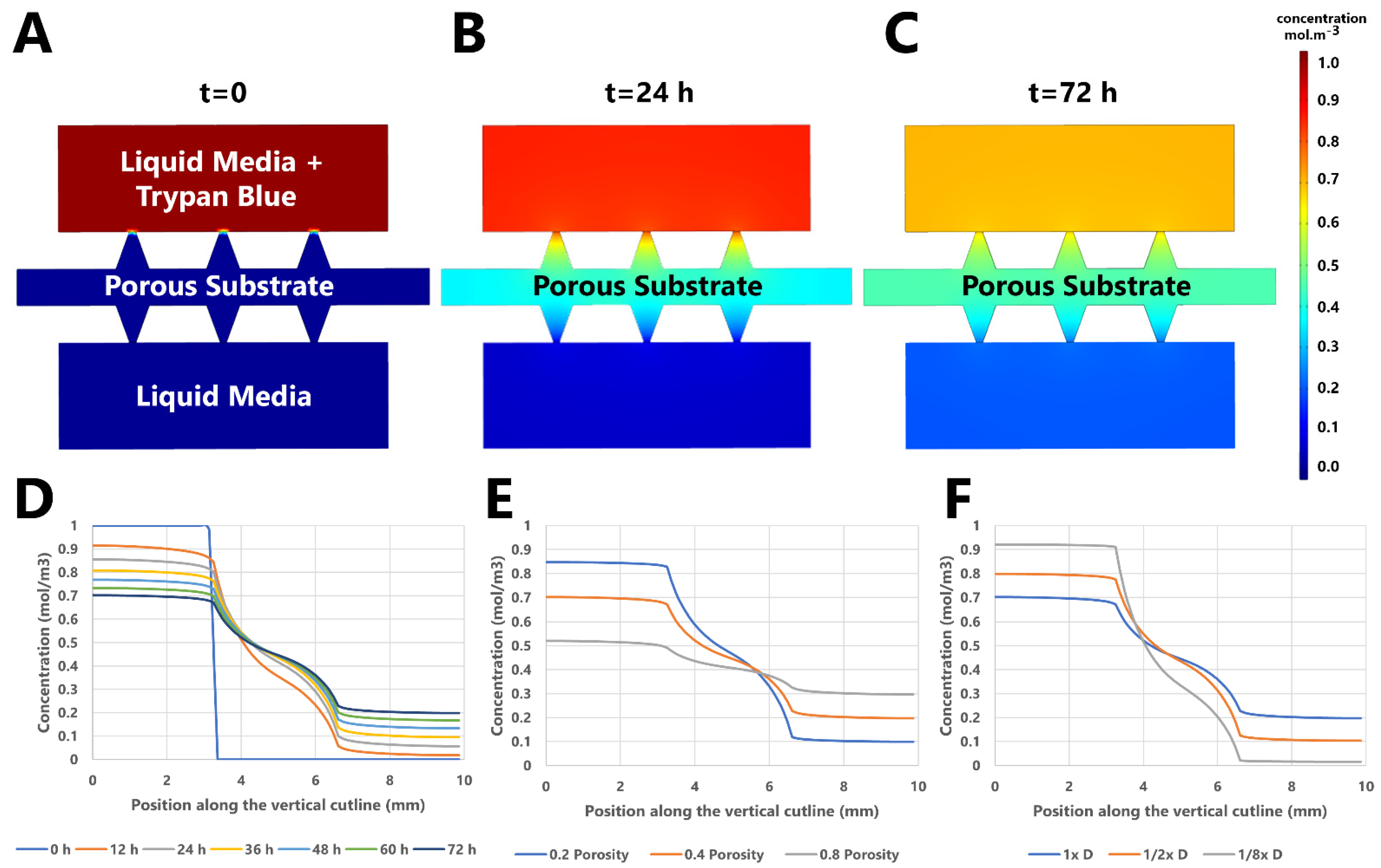
where is porosity of the matrix. One of the side channels of the chip was initially filled with a water solution defined by a particle concentration of , and the other channel was filled with pure water. The diffusion of the molecules through the porous membrane in the middle channel was simulated for a period of 72 h. Three different values of porosity, 0.2, 0.4, and 0.8, were simulated and compared. In addition, the diffusion coefficient for fluid was multiplied by 1/2 and 1/8 in order to see its effect on the concentration gradient.
2.2.13. Functional Immunofluorescent Staining
Fluorescent cell trackers were used for the identification of cell types and tracking their movements. Two different types of immunofluorescence dyes were used. CellTracker Green CMFDA dye (ThermoFisher Scientific) was used to stain SH-SHY5Y cells encapsulated inside GelMA at the middle channel, and Cell tracker Red CMTPX (ThermoFisher Scientific) was used for the HUVEC seeded into the top channel. Lyophilized dyes were dissolved in DMSO to the final concentration of 10 mM, and the solution was diluted in a 10 μM serum-free medium. The working solution was warmed to 37 °C prior to use. Two different protocols were used for each type of cell: staining protocol for cells in suspension (SH-SHY5Y) and staining protocol for adherent cells (HUVEC). For SH-SHY5Y, the cells were dyed before the UV photopolymerization process as the adherent cells required medium changes, which is not efficient for encapsulated cells. Prior to SH-SHY5Y cells being prepared for photopolymerization, they were centrifuged for 5 min, and the supernatant was aspirated. The working solution was used to resuspend the cells, and the cells were incubated in their growth environment at 37 °C, 5% CO2, and 95% humidity for 30 min. The cells were centrifuged and the working solution, Green CMFDA, was replaced with the growth medium, and the photopolymerization process was initiated. For HUVEC, at day 0, the growth medium inside the chip was removed and replaced with the working solution, Red CMTPX. Afterwards, the cells were incubated inside of a staining jar at 37 °C, 5% CO2, and 95% humidity for 30 min. The working solution was removed and replaced with a fresh medium with supplements. The fluorescent images were captured with an Olympus BX51 fluorescence microscope, stacked, and analyzed using ImageJ software.
3. Results
3.1. Field Emission Scanning Electron Microscopy Imaging of GelMA
Field emission scanning electron microscopy (FESEM) images of the lyophilized and hydrogel forms of GelMA were taken to image the surface morphology in both forms (Figure 2A). Lyophilized GelMA showed a patterned surface morphology with pores up to ~60 μm. In contrast, GelMA in a hydrogel form showed an irregular pattern of porous surface morphology, having more pores overall with smaller diameters.
3.2. Atomic Force Microscopy Analysis of GelMA
Atomic force microscopy (AFM) was used to image the structural properties of the GelMA hydrogel. A non-contact mode was used during scanning, resulting in 2D and 3D images (Figure 2B). The resulting images from the AFM topography provided complete information about the surface morphology, with the parameters of Sa (arithmetical mean deviation of surface 3D roughness), Sq (root-mean-square deviation of surface roughness topography), Sy (amplitude of height), Sp (height at peak), and Sv (height at valley). The mentioned values were obtained by operating the scanning procedure at a resonance frequency of 65 kHz and a force constant of 48 N m−1 over an area of 100.8 pm2, and they are organized in Table 4.
3.3. Fourier Transform Infrared Spectroscopy Analysis of GelMA
To confirm that the synthesized GelMA contained the desired compounds in its structure, Fourier transform infrared spectroscopy (FTIR) analysis was performed (Figure 2C). The hydrogel spectra showed a broad peak around 3300 cm−1. The peak around 1600 cm−1 is caused by C=O stretching groups. The smaller peak at 1500–1550 cm−1 refers to C–N–H structure. The FTIR spectra values correlated with the previously analyzed values of the GelMA, demonstrating that the synthesized GelMA had the desired chemical structure [74].
3.4. Swelling Test of the GelMA Inside the Microfluidic Chip
To visually confirm that the hydrogel inside the chip could swell enough liquid during overnight periods for a week, GelMA hydrogels were tested at days 1 and 7, respectively. A microfluidic environment containing co-cultured HUVEC and SH-SHY5Y cells was supplied with fresh medium on a daily basis. Prior to the test, the media from both the top and bottom channels were removed and replaced with trypan blue (Figure 2D, i and ii). The swelling process resulted in the middle medium channel swallowing a larger amount of liquid compared to the other channels, resulting in a darker blue color with no white space, meaning an efficient diffusion (Figure 2D, iii–v). Both of the hydrogels were able to swallow trypan blue efficiently overnight, which demonstrated that the hydrogels had the capability to swallow enough medium during overnight periods for at least 7 days.
3.5. Simulation Results
The ability of the chip to distribute particles by diffusion along its channels was simulated, and the concentration distribution results are visualized for the initial condition (Figure 3A), after 1 day (Figure 3B), and after 3 days (Figure 3C). Additionally, the change in the concentration distribution over 72 h on a vertical line in the chip for various hours throughout the study was organized in a diagram, as shown in Figure 3D. The simulation study also demonstrated that the diffusion speed increased with a higher porosity in the gel structure (Figure 3E). In addition, the simulation of smaller fluid diffusion coefficients in the porous matrix region demonstrated the diminishing effect on diffusion speed (Figure 3F).
3.6. Cell Viability Test
The viability of the encapsulated cells outside of the microfluidic platform was studied. HUVEC, SH-SHY5Y, and co-cultured HUVEC and SH-SHY5Y cells were encapsulated inside GelMA hydrogels on TMSPMA coated surface. For days 0, 1, 4, and 7 each, absorbance ratios of three different cell types were obtained, normalized, and quantitatively analyzed. The cell viability ratios of days 0, 1, 4, and 7, were 100%, 77%, 80%, and 82% for HUVEC cells, 100%, 80%, 82%, and 85% for SH-SHY5Y cells, and 100%, 70%, 85%, and 91% for co-cultured cells, respectively (Figure 4A). In addition, a comparison of the encapsulated co-cultured cells inside the GelMA hydrogel in different platforms was also studied (Figure 4B).
3.7. Cell Viability Imaging of GelMA Inside the Microfluidic Chip
To analyze the cell viability of the co-cultured HUVEC and SH-SHY5Y cells encapsulated in GelMA hydrogel inside the microfluidic chip, calcein AM and propidium iodide were used. Viability images of days 0, 1, 4, and 7 were taken (Figure 4C). The co-cultured cells inside the GelMA hydrogel in the microfluidic chip showed viability results of 83%, 75%, 84%, and 89% for days 0, 1, 4, and 7, respectively. A linear relationship was obtained between the viability values for both platforms (Table 5 and Table 6). There is a positive linear relationship at the 0.05 significant with a 70.4% correlation. Therefore, there is no significant positive or negative cellular viability difference between encapsulating cells inside GelMA hydrogels, outside or inside of a microfluidic chip, as cell viability values correlate with both.
3.8. Functional Immunostaining of Cells
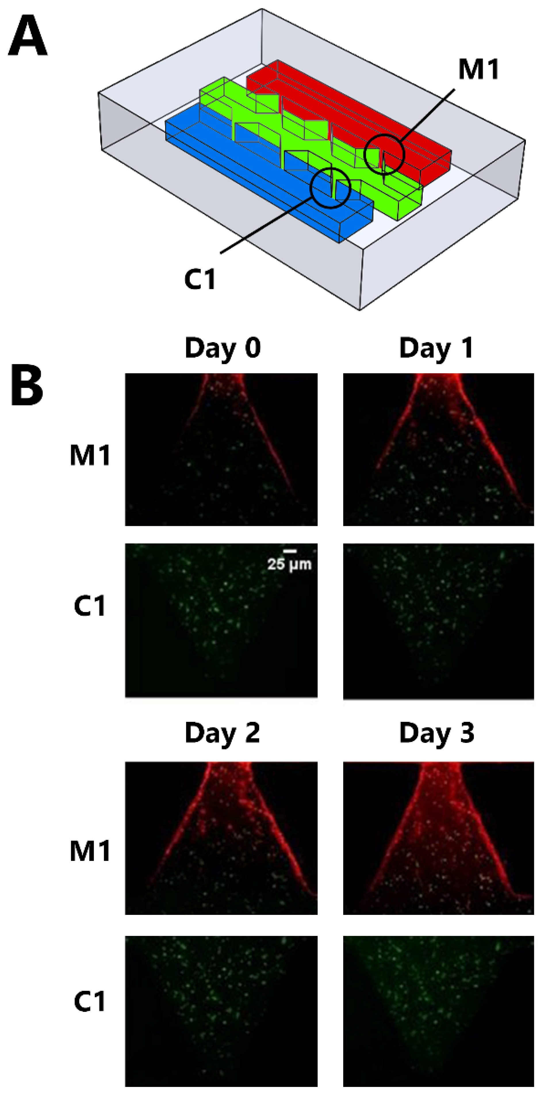
Two types of fluorescence cell dyes were used to track the localization of cells: CellTrackerTM Red CMTPX dye for HUVEC and CellTrackerTM Green CMFDA dye for SH-SHY5Y (Figure 5A). In addition to the localization of cells, the dyes were also used to observe the structural stability of the gel in the microfluidic chip throughout the study period. The first intersection points from each side were observed in this process, referred to as C1 and M1 (Figure 5A). Immunofluorescence images of these regions of interest on IC-Chip through 72 h were captured (Figure 5B). Immunofluorescence imaging demonstrated that GelMA could protect its structural stability for a duration of 72 h, allowing HUVEC migration through its porous structure.
4. Discussion
Modeling a structurally stable extracellular matrix (ECM) with the ability to mimic the natural extracellular environment of the cell efficiently is useful for tissue engineering applications. GelMA has shown structural stability and the ability to imitate the natural environment of the cell accurately. Using biocompatible gels, modeling cellular migration and invasion with conventional ways, such as using Matrigels (the solubilized basement membrane matrix secreted by Engelbreth-Holm-Swarm (EHS) mouse sarcoma cells), or well plates, are challenging when compared to utilizing photopolymerization on microfluidic systems. In conventional cases of modeling a 3D cell culture environment inside a microfluidic chip, Matrigels have been used. However, their drawbacks relating to mass manufacturing due to complex and inconvenient procedures, such as the necessity to use ice inside of the biosafety cabinet while forming the gel, means that they are less cost-efficient when compared to photopolymerizable GelMA hydrogels. On the other hand, as PDMS is being used as the main material to manufacture microfluidic devices, and these setups have high transparency, producing a GelMA hydrogel using photopolymerization on a microfluidic chip is a viable option for co-culturing and modeling migration/invasion studies.
4.1. Hydrogel Fabrication Inside the Microfluidic Chip Using UV Photopolymerization
Some desired properties, such as suitable shape and structure, are required by hydrogels for cell encapsulation. There are various strategies to fabricate biocompatible hydrogels that can mimic the ECM efficiently. However, options are narrow for the fabrication of hydrogels with the desired shape and that have inner structures that are stable in the long term. Three-dimensional printing is one of the main strategies utilized. Three-dimensional printing offers suitable resolution and precision; however, the process before printing is less convenient and more complex compared to UV photopolymerization. For UV photopolymerization, the process is rather simple, but the main concerns are the shape and the structural stability of the hydrogel, especially in the long term. As shown in this work, photopolymerization in a microfluidic environment had the ability to increase the structural stability of the gel in the long term while conveniently forming the gel in the desired shape. As compared to strategies such as Matrigels or 3D printing, UV photopolymerization is faster, as this method only requires 20 to 60 s to polymerize a gel.
The UV photopolymerization of GelMA has been widely used by us [75,76] and many well-established biomaterials research groups [62,70,71]. However, various aspects of the process of polymerization can influence cell viability, such as the concentration of the macromer, the type of the photoinitiator, and the wavelength and duration of the utilized light [77,78]. Among these factors, the macromer concentration can be easily optimized to maximize cell viability. In addition, the photoinitiator used in this study (Irgacure D-2959) has been reported to have relatively low cytotoxicity [79,80]. Furthermore, the current study, which utilized a UV-exposure intensity of 6.25 W cm−2 with an exposure time of 50 s, can be compared to a previous study that used a UV-exposure intensity of ~6 W·cm−2 for 10 min with low damage to the cells [80]. Hence, minimizing the possible negative effect of UV light can be carried out by selecting the most convenient type of photoinitiator for the study setup along with modifying the exposure dose (UV power and crosslinking time) [81,82,83,84].
4.2. Microfluidic Applications for Co-Culture and Migration Studies
Migration and invasion studies are easier to model on microchips compared to conventional methods mainly because of the ability to control and manipulate the fluid flow inside the channels, for example, by using gravitational force to control the fluid flow inside of the channels by simply placing the microchip in a horizontal position while in the incubation period promotes migration and invasion activities towards the direction of the gravitational force without needing extra protocols or environments such as transwell migration assay chambers or Matrigels. Additionally, compared to the conventional models, mechanical forces applied to the hydrogel are smaller as non-contact points organize the structural stability of the hydrogels while the intersection points allow for the controlled activity of co-culturing processes. Furthermore, mechanical forces are only applied in the desired locations, unlike conventional methods where mechanical forces such as shear stress are applied to a wider surface area of the gel, resulting in structures that are less viable for long-term applications. In addition to the mechanical properties and stability of a photoinitiated GelMA hydrogel inside a microfluidic chip, the cellular viability of the 3D matrix structure plays a vital role when conducting experiments to the desired duration. As shown in this work, the cellular viability inside the IC-Chip was almost the same as the cellular viability outside of this platform. Hence, there are no major drawbacks of using GelMA hydrogels on this platform when cellular viability is considered.
5. Conclusions
Neural-tissue modeling in tissue engineering that can allow for the building of accurate tissue models in 3D environments, which can mimic their natural environments in vivo, is one of the greatest challenges in this area, as animal tests suffer from complexity, ethical issues, and inaccuracy in regard to human tissue models. To overcome these challenges, neural tissue models have been developed to study the intra- and extra-cellular activities. In this research, a neural tissue model was developed in a microfluidic setup using the UV photopolymerization method to form the GelMA hydrogel structure in an IC-Chip, which is one of the most convenient, cost-efficient, easy-to-use microfluidic chips. This study showed that a neural tissue model could be created in a microchip in a short time for both short- and long-term studies.
In a nutshell, we demonstrated the co-culturing of two human cell lines inside the Invasion Chemotaxis (IC) microfluidic chip by the fabrication of the GelMA hydrogel inside the chip. By minimizing the mechanical forces applied to the surface area of the hydrogel structure inside the chip, the structural stability of the hydrogel lasted for more than 3 weeks, demonstrating that our approach is a suitable method for long-term studies. Furthermore, the cell viability results showed that the cells were viable inside the photopolymerized GelMA at the UV exposure duration needed to build the gel structure in the chip. Moreover, GelMA exhibited the desired biomechanical properties, and the viability of the cells was more than 80% for seven days. This work demonstrated a viable strategy to conduct co-culturing experiments as well as modeling invasion and migration events in a cost-efficient and easy-to-use microfluidic chip.
6. Future Prospects
The structural properties and bioavailability of GelMA hydrogels were examined inside and outside of the microfluidic chip with the co-culturing of a neurovascular tissue structure. In addition to the neurovascular research applications of this setup, the developed environment can also be suitable for modeling various types of cancer and examining the invasion and migration of various types of cancer or tumor cells. Furthermore, this platform can enable chemotaxis studies, allowing chemoattractants to be used for the promotion of the migration of cells from the selected channels. As the design of the microfluidic devices enables the user to “mold” their hydrogel patterns easily without a surface coating or chemical or mechanical functionalization, patterning the desired shape and sustaining the cell environment in a matrix is rapid and convenient. Our experiment proved that photo-initiating GelMA hydrogel inside a well-designed microfluidic chip is a viable strategy for conducting co-culturing experiments as well as modeling invasion and migration events. This property can also be used in experimental studies for drug delivery and drug dosage optimization studies on various diseases. In addition, by precisely controlling the fluid flow inside of the channels, studies on drug delivery speed and frequency can be conducted using this model. In addition, using the developed model, the effects of drugs or various molecules on the cell’s encapsulated 3D environment can also be tested by using entities alongside the seeded cells or only with the medium at the selected channels.
Author Contributions
Conceptualization S.T., E.S.; methodology, S.T., E.S.; software, M.T.B.; validation, Z.L.C.; formal analysis, E.S., Z.L.C.; investigation, E.S., Z.L.C.; data curation, Z.L.C.; writing—original draft preparation, Z.L.C., M.R.S., H.S.B.; writing—review and editing, E.S., S.T.; visualization, M.R.S., M.T.B.; supervision, S.T., E.S.; project administration, S.T., E.S.; funding acquisition, S.T., E.S. All authors have read and agreed to the published version of the manuscript.
Funding
S.T. acknowledges Marie Skłodowska-Curie Individual Fellowship (101003361), Tubitak 2232 International Fellowship for Outstanding Researchers Award (118C391), Alexander von Humboldt Research Fellowship for Experienced Researchers, and Royal Academy Newton-Katip Çelebi Transforming Systems Through Partnership award for financial support of this research. This work was partially supported by Science Academy’s Young Scientist Awards Program (BAGEP), Outstanding Young Scientists Awards (GEBİP), and Bilim Kahramanlari Dernegi The Young Scientist Award. Opinions, interpretations, conclusions, and recommendations are those of the author and are not necessarily endorsed by the TÜBİTAK.
Institutional Review Board Statement
Human umbilical vein endothelial cell (HUVEC) was obtained from Ozan Karaman and neuroblastoma cell (SH-SY5Y) lines was obtained from Taner Dagci.
Informed Consent Statement
Not applicable.
Data Availability Statement
The data that support the findings of this study are available from the corresponding author upon reasonable request.
Conflicts of Interest
The authors have no other relevant affiliations or financial involvement with any organization or entity with a financial interest in or financial conflict with the subject matter or materials discussed in the manuscript apart from those disclosed.
References
- Huh, D.; Hamilton, G.A.; Ingber, D.E. From 3D cell culture to organs-on-chips. Trends Cell Biol. 2011, 21, 745–754. [Google Scholar] [CrossRef] [PubMed] [Green Version]
- Guttenplan, A.P.M.; Birgani, Z.T.; Giselbrecht, S.; Truckenmüller, R.K.; Habibović, P. Chips for Biomaterials and Biomaterials for Chips: Recent Advances at the Interface between Microfabrication and Biomaterials Research. Adv. Healthc. Mater. 2021, 10, 2100371. [Google Scholar] [CrossRef] [PubMed]
- Low, L.A.; Tagle, D.A. Tissue chips—Innovative tools for drug development and disease modeling. Lab Chip 2017, 17, 3026–3036. [Google Scholar] [CrossRef] [PubMed]
- Bai, J.; Wang, C. Organoids and Microphysiological Systems: New Tools for Ophthalmic Drug Discovery. Front. Pharmacol. 2020, 11, 407. [Google Scholar] [CrossRef] [Green Version]
- Kleinstreuer, N.; Holmes, A. Harnessing the power of microphysiological systems for COVID-19 research. Drug Discov. Today 2021, 26, 2496–2501. [Google Scholar] [CrossRef]
- Signore, M.A.; De Pascali, C.; Giampetruzzi, L.; Siciliano, P.A.; Francioso, L. Gut-on-Chip microphysiological systems: Latest advances in the integration of sensing strategies and adoption of mature detection mechanisms. Sens. Bio-Sens. Res. 2021, 33, 100443. [Google Scholar] [CrossRef]
- Sarabi, M.R.; Yetisen, A.K.; Tasoglu, S. Magnetic levitation for space exploration. Trends Biotechnol. 2022; in press. [Google Scholar] [CrossRef]
- Rahmani Dabbagh, S.; Sarabi, M.R.; Birtek, M.T.; Mustafaoglu, N.; Zhang, Y.S.; Tasoglu, S. 3D bioprinted organ-on-chips. Aggregate 2022, e197. [Google Scholar] [CrossRef]
- Yigci, D.; Sarabi, M.R.; Ustun, M.; Atceken, N.; Sokullu, E.; Onder, T.B.; Tasoglu, S. 3D Bioprinted Glioma Models. Prog. Biomed. Eng. 2022. [Google Scholar] [CrossRef]
- Shi, T.; Cheung, M. Urine-derived induced pluripotent/neural stem cells for modeling neurological diseases. Cell Biosci. 2021, 11, 85. [Google Scholar] [CrossRef]
- Hernandez, H. Engineering Human iPSC-Derived Skeletal Muscle to Model Pompe Disease: Towards Novel Gene and Regenerative Therapies; Erasmus University Rotterdam: Rotterdam, The Netherlands, 2021. [Google Scholar]
- Santoso, J.W.; McCain, M.L. Neuromuscular disease modeling on a chip. Dis. Model. Mech. 2020, 13, dmm044867. [Google Scholar] [CrossRef] [PubMed]
- Chang, C.-Y.; Ting, H.-C.; Liu, C.-A.; Su, H.-L.; Chiou, T.-W.; Lin, S.-Z.; Harn, H.-J.; Ho, T.-J. Induced pluripotent stem cell (iPSC)-based neurodegenerative disease models for phenotype recapitulation and drug screening. Molecules 2020, 25, 2000. [Google Scholar]
- Lynch, E.; Peek, E.; Reilly, M.; FitzGibbons, C.; Robertson, S.; Suzuki, M. Current Progress in the Creation, Characterization, and Application of Human Stem Cell-derived in Vitro Neuromuscular Junction Models. Stem Cell Rev. Rep. 2021, 18, 768–780. [Google Scholar] [CrossRef] [PubMed]
- Fabre, K.M.; Livingston, C.; Tagle, D.A. Organs-on-chips (microphysiological systems): Tools to expedite efficacy and toxicity testing in human tissue. Exp. Biol. Med. 2014, 239, 1073–1077. [Google Scholar] [CrossRef] [PubMed]
- Sun, A.M.; Hoffman, T.; Luu, B.Q.; Ashammakhi, N.; Li, S. Application of lung microphysiological systems to COVID-19 modeling and drug discovery: A review. Bio-Design Manuf. 2021, 4, 757–775. [Google Scholar] [CrossRef]
- Doherty, E.L.; Aw, W.Y.; Hickey, A.J.; Polacheck, W.J. Microfluidic and Organ-on-a-Chip Approaches to Investigate Cellular and Microenvironmental Contributions to Cardiovascular Function and Pathology. Front. Bioeng. Biotechnol. 2021, 9, 624435. [Google Scholar] [CrossRef]
- Lesher-Perez, S.C.; Frampton, J.P.; Takayama, S. Microfluidic systems: A new toolbox for pluripotent stem cells. Biotechnol. J. 2012, 8, 180–191. [Google Scholar] [CrossRef] [Green Version]
- Haring, A.P.; Sontheimer, H.; Johnson, B.N. Microphysiological Human Brain and Neural Systems-on-a-Chip: Potential Alternatives to Small Animal Models and Emerging Platforms for Drug Discovery and Personalized Medicine. Stem Cell Rev. Rep. 2017, 13, 381–406. [Google Scholar] [CrossRef]
- Holmes, A.M.; Solari, R.; Holgate, S.T. Animal models of asthma: Value, limitations and opportunities for alternative approaches. Drug Discov. Today 2011, 16, 659–670. [Google Scholar] [CrossRef]
- Singh, Y.P.; Moses, J.C.; Bhardwaj, N.; Mandal, B.B. Overcoming the Dependence on Animal Models for Osteoarthritis Therapeutics—The Promises and Prospects of In Vitro Models. Adv. Healthc. Mater. 2021, 10, 2100961. [Google Scholar] [CrossRef]
- Hofer, M.; Lutolf, M.P. Engineering organoids. Nat. Rev. Mater. 2021, 6, 402–420. [Google Scholar] [CrossRef] [PubMed]
- Knowlton, S.; Yenilmez, B.; Tasoglu, S. Towards Single-Step Biofabrication of Organs on a Chip via 3D Printing. Trends Biotechnol. 2016, 34, 685–688. [Google Scholar] [CrossRef] [PubMed]
- Ustun, M.; Dabbagh, S.R.; Ilci, I.; Bagci-Onder, T.; Tasoglu, S. Glioma-on-a-Chip Models. Micromachines 2021, 12, 490. [Google Scholar] [CrossRef] [PubMed]
- Liu, J.; Mosavati, B.; Oleinikov, A.V.; Du, E. Biosensors for Detection of Human Placental Pathologies: A Review of Emerging Technologies and Current Trends. Transl. Res. 2019, 213, 23–49. [Google Scholar] [CrossRef] [PubMed]
- Mosavati, B.; Oleinikov, A.V.; Du, E. Development of an Organ-on-a-Chip-Device for Study of Placental Pathologies. Int. J. Mol. Sci. 2020, 21, 8755. [Google Scholar] [CrossRef] [PubMed]
- Teixeira, S.P.B.; Domingues, R.M.A.; Shevchuk, M.; Gomes, M.E.; Peppas, N.A.; Reis, R.L. Biomaterials for Sequestration of Growth Factors and Modulation of Cell Behavior. Adv. Funct. Mater. 2020, 30, 1909011. [Google Scholar] [CrossRef]
- Wang, Y.; Kankala, R.K.; Ou, C.; Chen, A.; Yang, Z. Advances in hydrogel-based vascularized tissues for tissue repair and drug screening. Bioact. Mater. 2021, 9, 198–220. [Google Scholar] [CrossRef]
- Geraili, A.; Jafari, P.; Hassani, M.S.; Araghi, B.H.; Mohammadi, M.H.; Ghafari, A.M.; Tamrin, S.H.; Modarres, H.P.; Kolahchi, A.R.; Ahadian, S.; et al. Controlling Differentiation of Stem Cells for Developing Personalized Organ-on-Chip Platforms. Adv. Healthc. Mater. 2017, 7, 1700426. [Google Scholar] [CrossRef] [Green Version]
- Sarabi, M.; Ahmadpour, A.; Yetisen, A.; Tasoglu, S. Finger-Actuated Microneedle Array for Sampling Body Fluids. Appl. Sci. 2021, 11, 5329. [Google Scholar] [CrossRef]
- Herbert, R.; Lim, H.; Park, S.; Kim, J.; Yeo, W. Recent Advances in Printing Technologies of Nanomaterials for Implantable Wireless Systems in Health Monitoring and Diagnosis. Adv. Healthc. Mater. 2021, 10, e2100158. [Google Scholar] [CrossRef]
- Peng, X.; Dong, K.; Wu, Z.; Wang, J.; Wang, Z.L. A review on emerging biodegradable polymers for environmentally benign transient electronic skins. J. Mater. Sci. 2021, 56, 16765–16789. [Google Scholar] [CrossRef]
- Ashammakhi, N.; Hernandez, A.L.; Unluturk, B.D.; Quintero, S.A.; de Barros, N.R.; Apu, E.H.; Shams, A.B.; Ostrovidov, S.; Li, J.; Contag, C.; et al. Biodegradable Implantable Sensors: Materials Design, Fabrication, and Applications. Adv. Funct. Mater. 2021, 31, 2104149. [Google Scholar] [CrossRef]
- Hosseini, E.S.; Dervin, S.; Ganguly, P.; Dahiya, R. Biodegradable Materials for Sustainable Health Monitoring Devices. ACS Appl. Bio Mater. 2020, 4, 163–194. [Google Scholar] [CrossRef]
- Bilirgen, A.C.; Toker, M.; Odabas, S.; Yetisen, A.K.; Garipcan, B.; Tasoglu, S. Plant-Based Scaffolds in Tissue Engineering. ACS Biomater. Sci. Eng. 2021, 7, 926–938. [Google Scholar] [CrossRef] [PubMed]
- Yenilmez, B.; Temirel, M.; Knowlton, S.; Lepowsky, E.; Tasoglu, S. Development and characterization of a low-cost 3D bioprinter. Bioprinting 2019, 13, e00044. [Google Scholar] [CrossRef]
- Knowlton, S.; Cho, Y.; Li, X.J.; Khademhosseini, A.; Tasoglu, S. Utilizing stem cells for three-dimensional neural tissue engineering. Biomater. Sci. 2016, 4, 768–784. [Google Scholar] [CrossRef]
- Feig, V.R.; Tran, H.; Bao, Z. Biodegradable Polymeric Materials in Degradable Electronic Devices. ACS Cent. Sci. 2018, 4, 337–348. [Google Scholar] [CrossRef] [Green Version]
- Bhatia, S. Natural Polymer Drug Delivery Systems: Nanoparticles, Plants, and Algae; Springer International Publishing: Cham, Switzerland, 2016. [Google Scholar] [CrossRef]
- Chiong, J.A.; Tran, H.; Lin, Y.; Zheng, Y.; Bao, Z. Integrating Emerging Polymer Chemistries for the Advancement of Recyclable, Biodegradable, and Biocompatible Electronics. Adv. Sci. 2021, 8, 2101233. [Google Scholar] [CrossRef]
- Anwar, M.; Muhammad, F.; Akhtar, B. Biodegradable nanoparticles as drug delivery devices. J. Drug Deliv. Sci. Technol. 2021, 64, 102638. [Google Scholar] [CrossRef]
- John, N. Bio-Implants Derived from Biocompatible and Biodegradable Biopolymeric Materials. In Advanced Studies in Experimental and Clinical Medicine; Apple Academic Press: Palm Bay, FL, USA, 2021; pp. 53–81. [Google Scholar] [CrossRef]
- Pyarasani, R.D.; Jayaramudu, T.; John, A. Polyaniline-based conducting hydrogels. J. Mater. Sci. 2018, 54, 974–996. [Google Scholar] [CrossRef]
- Jammalamadaka, U.; Tappa, K. Recent Advances in Biomaterials for 3D Printing and Tissue Engineering. J. Funct. Biomater. 2018, 9, 22. [Google Scholar] [CrossRef] [PubMed] [Green Version]
- Murugan, S.; Parcha, S.R. Fabrication techniques involved in developing the composite scaffolds PCL/HA nanoparticles for bone tissue engineering applications. J. Mater. Sci. Mater. Med. 2021, 32, 93. [Google Scholar] [CrossRef] [PubMed]
- Sarabi, M.R.; Bediz, B.; Falo, L.D.; Korkmaz, E.; Tasoglu, S. 3D printing of microneedle arrays: Challenges towards clinical translation. J. 3D Print. Med. 2021, 5, 65–70. [Google Scholar] [CrossRef]
- Tyagi, N.; Gambhir, K.; Kumar, S.; Gangenahalli, G.; Verma, Y.K. Interplay of reactive oxygen species (ROS) and tissue engineering: A review on clinical aspects of ROS-responsive biomaterials. J. Mater. Sci. 2021, 56, 16790–16823. [Google Scholar] [CrossRef]
- Pourjavadi, A.; Heydarpour, R.; Tehrani, Z.M. Multi-stimuli-responsive hydrogels and their medical applications. New J. Chem. 2021, 45, 15705–15717. [Google Scholar] [CrossRef]
- Goldhahn, C.; Cabane, E.; Chanana, M. Sustainability in wood materials science: An opinion about current material development techniques and the end of lifetime perspectives. Philos. Trans. R. Soc. Lond. Ser. A Math. Phys. Eng. Sci. 2021, 379, 20200339. [Google Scholar] [CrossRef]
- Sampson, K.L.; Deore, B.; Go, A.; Nayak, M.A.; Orth, A.; Gallerneault, M.; Malenfant, P.R.L.; Paquet, C. Multimaterial Vat Polymerization Additive Manufacturing. ACS Appl. Polym. Mater. 2021, 3, 4304–4324. [Google Scholar] [CrossRef]
- Zheng, N.; Xu, Y.; Zhao, Q.; Xie, T. Dynamic Covalent Polymer Networks: A Molecular Platform for Designing Functions beyond Chemical Recycling and Self-Healing. Chem. Rev. 2021, 121, 1716–1745. [Google Scholar] [CrossRef]
- Xiang, D.; Liu, Y.; Zhou, E.; Wang, Y. Advances in the applications of polymer biomaterials for in vitro follicle culture. Biomed. Pharmacother. 2021, 140, 111422. [Google Scholar] [CrossRef]
- Green, R.; Baek, S.; Poole-Warren, L.; Martens, P.J. Conducting polymer-hydrogels for medical electrode applications. Sci. Technol. Adv. Mater. 2010, 11, 014107. [Google Scholar] [CrossRef] [Green Version]
- Meyer, M.; Dohmen, C.; Philipp, A.; Kiener, D.; Maiwald, G.; Scheu, C.; Ogris, M.; Wagner, E. Synthesis and biological evaluation of a bioresponsive and endosomolytic siRNA−Polymer conjugate. Mol. Pharm. 2009, 6, 752–762. [Google Scholar] [CrossRef] [PubMed]
- Ahmad, A.; Mubarak, N.; Jannat, F.T.; Ashfaq, T.; Santulli, C.; Rizwan, M.; Najda, A.; Bin-Jumah, M.; Abdel-Daim, M.M.; Hussain, S.; et al. A Critical Review on the Synthesis of Natural Sodium Alginate Based Composite Materials: An Innovative Biological Polymer for Biomedical Delivery Applications. Processes 2021, 9, 137. [Google Scholar] [CrossRef]
- Xu, W.; Jambhulkar, S.; Zhu, Y.; Ravichandran, D.; Kakarla, M.; Vernon, B.; Lott, D.G.; Cornella, J.L.; Shefi, O.; Miquelard-Garnier, G.; et al. 3D printing for polymer/particle-based processing: A review. Compos. Part B Eng. 2021, 223, 109102. [Google Scholar] [CrossRef]
- Ellis, L.D.; Rorrer, N.A.; Sullivan, K.P.; Otto, M.; McGeehan, J.E.; Román-Leshkov, Y.; Wierckx, N.; Beckham, G.T. Chemical and biological catalysis for plastics recycling and upcycling. Nat. Catal. 2021, 4, 539–556. [Google Scholar] [CrossRef]
- McClements, D.J.; Rao, J. Food-grade nanoemulsions: Formulation, fabrication, properties, performance, biological fate, and potential toxicity. Crit. Rev. Food Sci. Nutr. 2011, 51, 285–330. [Google Scholar] [CrossRef]
- Papkovsky, D.B.; Dmitriev, R.I. Biological detection by optical oxygen sensing. Chem. Soc. Rev. 2013, 42, 8700–8732. [Google Scholar] [CrossRef]
- Goldberg, M.; Langer, R.; Jia, X. Nanostructured materials for applications in drug delivery and tissue engineering. J. Biomater. Sci. Polym. Ed. 2007, 18, 241–268. [Google Scholar] [CrossRef] [Green Version]
- Hoyle, C.E.; Lowe, A.B.; Bowman, C.N. Thiol-click chemistry: A multifaceted toolbox for small molecule and polymer synthesis. Chem. Soc. Rev. 2010, 39, 1355–1387. [Google Scholar] [CrossRef]
- Dumur, F.; Gigmes, D.; Fouassier, J.-P.; Lalevée, J. Organic Electronics: An El Dorado in the Quest of New Photocatalysts for Polymerization Reactions. Acc. Chem. Res. 2016, 49, 1980–1989. [Google Scholar] [CrossRef]
- Kaya, K.; Jockusch, S.; Yagci, Y. Mussel-Inspired Coatings by Photoinduced Electron-Transfer Reactions: Photopolymerization of Dopamine under UV, Visible, and Daylight under Oxygen-Free Conditions. Macromolecules 2021, 54, 5991–5999. [Google Scholar] [CrossRef]
- Ghaderinezhad, F.; Ceylan Koydemir, H.; Tseng, D.; Karinca, D.; Liang, K.; Ozcan, A.; Tasoglu, S. Sensing of electrolytes in urine using a miniaturized paper-based device. Sci. Rep. 2020, 10, 1–9. [Google Scholar] [CrossRef] [PubMed]
- Amin, R.; Li, L.; Tasoglu, S. Assessing reusability of microfluidic devices: Urinary protein uptake by PDMS-based channels after long-term cyclic use. Talanta 2019, 192, 455–462. [Google Scholar] [CrossRef] [PubMed]
- Tasoglu, S. Toilet-based continuous health monitoring using urine. Nat. Rev. Urol. 2022, 19, 219–230. [Google Scholar] [CrossRef] [PubMed]
- Temirel, M.; Yenilmez, B.; Tasoglu, S. Long-term cyclic use of a sample collector for toilet-based urine analysis. Sci. Rep. 2021, 11, 2170. [Google Scholar] [CrossRef]
- Dabbagh, S.R.; Rabbi, F.; Doğan, Z.; Yetisen, A.K.; Tasoglu, S. Machine learning-enabled multiplexed microfluidic sensors. Biomicrofluidics 2020, 14, 061506. [Google Scholar] [CrossRef]
- Yue, K.; Trujillo-de Santiago, G.; Alvarez, M.M.; Tamayol, A.; Annabi, N.; Khademhosseini, A. Synthesis, properties, and biomedical applications of gelatin methacryloyl (GelMA) hydrogels. Biomaterials 2015, 73, 254–271. [Google Scholar] [CrossRef] [Green Version]
- Aldana, A.A.; Malatto, L.; Rehman, M.A.U.; Boccaccini, A.R.; Abraham, G.A. Fabrication of Gelatin Methacrylate (GelMA) Scaffolds with Nano- and Micro-Topographical and Morphological Features. Nanomaterials 2019, 9, 120. [Google Scholar] [CrossRef] [Green Version]
- Tyrrell, H. The origin and present status of Fick’s diffusion law. J. Chem. Educ. 1964, 41, 397. [Google Scholar] [CrossRef]
- Miller, C.C. The Stokes-Einstein law for diffusion in solution. Proc. R. Soc. A Math. Phys. Eng. Sci. 1924, 106, 724–749. [Google Scholar]
- Millington, R.J.; Quirk, J.P. Permeability of porous solids. Trans. Faraday Soc. 1961, 57, 1200–1207. [Google Scholar] [CrossRef]
- Leggio, L.; Vivarelli, S.; L’Episcopo, F.; Tirolo, C.; Caniglia, S.; Testa, N.; Marchetti, B.; Iraci, N. microRNAs in Parkinson’s Disease: From Pathogenesis to Novel Diagnostic and Therapeutic Approaches. Int. J. Mol. Sci. 2017, 18, 2698. [Google Scholar] [CrossRef] [PubMed] [Green Version]
- Tasoglu, S.; Yu, C.; Gungordu, H.I.; Guven, S.; Vural, T.; Demirci, U. Guided and magnetic self-assembly of tunable magnetoceptive gels. Nat. Commun. 2014, 5, 4702. [Google Scholar] [CrossRef] [PubMed] [Green Version]
- Tasoglu, S.; Diller, E.; Guven, S.; Sitti, M.; Demirci, U. Untethered micro-robotic coding of three-dimensional material composition. Nat. Commun. 2014, 5, 3124. [Google Scholar] [CrossRef] [PubMed]
- Knowlton, S.; Yenilmez, B.; Anand, S.; Tasoglu, S. Photocrosslinking-based bioprinting: Examining crosslinking schemes. Bioprinting 2017, 5, 10–18. [Google Scholar] [CrossRef]
- Noshadi, I.; Hong, S.; Sullivan, K.E.; Sani, E.S.; Portillo-Lara, R.; Tamayol, A.; Shin, S.R.; Gao, A.E.; Stoppel, W.L.; Black, L.D., III; et al. In vitro and in vivo analysis of visible light crosslinkable gelatin methacryloyl (GelMA) hydrogels. Biomater. Sci. 2017, 5, 2093–2105. [Google Scholar] [CrossRef]
- Williams, C.G.; Malik, A.N.; Kim, T.K.; Manson, P.N.; Elisseeff, J.H. Variable cytocompatibility of six cell lines with photoinitiators used for polymerizing hydrogels and cell encapsulation. Biomaterials 2005, 26, 1211–1218. [Google Scholar] [CrossRef]
- Monteiro, N.; Thrivikraman, G.; Athirasala, A.; Tahayeri, A.; Franca, C.; Ferracane, J.L.; Bertassoni, L.E. Photopolymerization of cell-laden gelatin methacryloyl hydrogels using a dental curing light for regenerative dentistry. Dent. Mater. 2018, 34, 389–399. [Google Scholar] [CrossRef]
- Li, Q.; Wang, J.; Shahani, S.; Sun, D.D.; Sharma, B.; Elisseeff, J.H.; Leong, K.W. Biodegradable and photocrosslinkable polyphosphoester hydrogel. Biomaterials 2006, 27, 1027–1034. [Google Scholar] [CrossRef] [Green Version]
- Rezapour Sarabi, M.; Alseed, M.M.; Karagoz, A.A.; Tasoglu, S. Machine Learning-Enabled Prediction of 3D-Printed Microneedle Features. Biosensors 2022, 12, 491. [Google Scholar] [CrossRef]
- Bryant, S.J.; Nuttelman, C.R.; Anseth, K.S. Cytocompatibility of UV and visible light photoinitiating systems on cultured NIH/3T3 fibroblasts in vitro. J. Biomater. Sci. Polym. Ed. 2000, 11, 439–457. [Google Scholar] [CrossRef]
- Hwangbo, H.; Lee, H.; Jin, E.; Lee, J.; Jo, Y.; Ryu, D.; Kim, G. Bio-printing of aligned GelMa-based cell-laden structure for muscle tissue regeneration. Bioact. Mater. 2022, 8, 57–70. [Google Scholar] [CrossRef] [PubMed]
Figure 1.
Curing Gelatin Methacryloyl (GelMA) using ultraviolet (UV) light and co-culturing two cell lines inside the microfluidic chip. (A) Schematical design of the Invasion Chemotaxis Chip (IC-Chip) and (B) The actual setup of the chip used in this study (Scale bar: 250 μm). (C) Microfluidic chip setup preparation process includes steps of (i) Injecting GelMA along with neuroblastoma cells (SH-SHY5Y) to the middle channel. (ii) Curing the GelMA with UV light. (iii) Addition of medium with human umbilical vein endothelial cell (HUVEC) (shown in red) to the top channel and medium without cells (in green) to the bottom channel of the chip. (iv) Upon filling the channels, the chip was put inside of a staining jar for incubation with bottom channel at the top to accelerate medium flow through the middle channel. (v) The chip was rotated upside down to promote cell movement towards the gel. (D) Media in both top and bottom channels were removed and replaced with calcein AM and propidium iodide, respectively, for the purpose of locating the dead and alive cells inside the hydrogel. Fluorescence imaging shows the distribution of calcein AM/propidium iodide marked cells inside the microfluidic chip (Scale bar: 50 μm).

Figure 2.
(A) Field emission electron microscopy (FESEM) images of the GelMA surface. Scale bars are 10 μm (left) and 100 μm (right). Porosities are marked with star. (B) Non-Contact mode atomic force microscopy (AFM) scanning of the GelMA surface, shown in a 2D image (top) and a 3D image (bottom). Analysis parameters and measured results are organized in the table. (C) Fourier transform infrared spectrophotometry (FTIR) of GelMA and gelatin. (D) Swelling test included steps of (i) removing the media from top and bottom channels of the chip and (ii) replacing them with trypan blue. (iii) The initial state of the microfluidic chip with trypan blue. After this process, the permeability of the hydrogel was observed visually. (iv) Day 1 image and (v) Day 7 image of the chip after incubating with trypan blue overnight.

Figure 3.
Finite element simulation of the process of trypan blue diffusion and its transport across the microfluidic platform and the chambers. Contour plot of the trypan blue concentration along the chip for a gel structure with 40% porosity for (A) initial condition, (B) after 24 h, and (C) after 72 h. (D) Concentration variation with time over a central vertical cutline length for 40% porosity. (E) Concentration over the vertical cutline for different porosity values applied on the porous substrate at 72 h. (F) Concentration over the vertical cutline for different diffusion coefficients applied on the porous substrate at 72 h.

Figure 4.
Cell viability experiment results. (A) The alamarBlue cell viability test results of human umbilical vein endothelial cell (HUVEC) and neuroblastoma cells (SH-SHY5Y) encapsulated into GelMA hydrogel (n = 3). (B) Comparison of encapsulated co-cultured cells inside of GelMA hydrogel in different platforms (n = 3). (C) The cell viability images of co-cultured HUVEC and SH-SHY5Y cells inside of GelMA hydrogel.

Figure 5.
Cell migration results (n = 3). (A) Schematics of the experimental setup used to observe cell migration inside of the GelMA structure. M1 and C1 refer to regions of interest where images were taken. The channel painted with red color contains human umbilical vein endothelial cell (HUVEC) along with growth medium. On the other hand, the channel painted with green color contains neuroblastoma cell line (SH-SHY5Y) along with GelMA. Blue channel contains only growth medium, and it was considered as the control medium. (B) Immunofluorescence images of selected regions of interest on IC-Chip through 72 h. HUVEC was dyed with red immunofluorescence dye, whereas SH-SHY5Y was dyed with green dye. Immunofluorescence imaging demonstrated that GelMA could protect its structural stability for the duration of 72 h, letting HUVEC migrate through its porous structure.


Table 1.
Nomenclature.
| Abbreviation/Symbol | Explanation |
|---|---|
| HUVEC | Human umbilical vein endothelial cell line |
| SH-SY5Y | Human neuroblastoma cell line |
| Diffusive flux | |
| The fluid diffusion coefficient | |
| The diffusion coefficient inside the porous matrix | |
| Concentration | |
| The Boltzmann constant | |
| Temperature | |
| Dynamic viscosity | |
| Radius of the diffusing particle | |
| Porosity of the matrix |
Table 2.
Specifications of the Invasion Chemotaxis microfluidic chip (IC-Chip).
| Side Channels | Middle Channel | |
|---|---|---|
| Height | 150 μm | 150 μm |
| Width | 3250 μm | 1125 μm (the narrow parts); 3375 μm (the wide parts) |
| Injection Volume | 20 μL | 20 μL |
| Diameter of Inlets | 1000 μm | 1000 μm |
Table 3.
UV Curing parameters for the hydrogel fabrication inside of the microfluidic chip.
| UV Exposure Duration | 50 s |
| Microchip Distance from the UV Source | 60 mm |
| Irradiance Level | 6.25 W cm−2 |
| GelMA Concentration | 10% |
| Photoinitiator Concentration | 1% |
| Cell Concentration | 5 × 10⁵ mL−1 |
Table 4.
Analysis parameters and measured results in atomic force microscopy (AFM) scanning of the GelMA surface.
Table 4.
Analysis parameters and measured results in atomic force microscopy (AFM) scanning of the GelMA surface.
| Area | 100.8 pm2 |
| Sa | 7.3136 nm |
| Sq | 9.9188 nm |
| Sy | 116.32 nm |
| Sp | 74.854 nm |
| Sv | −41.464 nm |
| Sm | −5.7364 fm |
Table 5.
Mean and standard deviation values of cell viabilities inside of different platforms (N = 12).
Table 5.
Mean and standard deviation values of cell viabilities inside of different platforms (N = 12).
| Mean | Std Deviation | N | |
|---|---|---|---|
| IC-Chip | 82.500 | 5.632 | 12 |
| Petri Dish | 86.416 | 11.766 | 12 |
Table 6.
Pearson correlation values of cellular viability of co-cultures in different platforms.
| KERRYPNX | IC-Chip | Petri Dish | |
|---|---|---|---|
| IC-Chip | Pearson Correlation | 1 | 0.704 |
| Sig. (2-tailed) | - | 0.011 | |
| N | 12 | 12 | |
| Petri Dish | Pearson Correlation | 0.704 | 1 |
| Sig. (2-tailed) | 0.011 | - | |
| N | 12 | 12 | |
Publisher’s Note: MDPI stays neutral with regard to jurisdictional claims in published maps and institutional affiliations. |
© 2022 by the authors. Licensee MDPI, Basel, Switzerland. This article is an open access article distributed under the terms and conditions of the Creative Commons Attribution (CC BY) license (https://creativecommons.org/licenses/by/4.0/).
Share and Cite
MDPI and ACS Style
Sokullu, E.; Cücük, Z.L.; Sarabi, M.R.; Birtek, M.T.; Bagheri, H.S.; Tasoglu, S. Microfluidic Invasion Chemotaxis Platform for 3D Neurovascular Co-Culture. Fluids 2022, 7, 238. https://doi.org/10.3390/fluids7070238
AMA Style
Sokullu E, Cücük ZL, Sarabi MR, Birtek MT, Bagheri HS, Tasoglu S. Microfluidic Invasion Chemotaxis Platform for 3D Neurovascular Co-Culture. Fluids. 2022; 7(7):238. https://doi.org/10.3390/fluids7070238
Chicago/Turabian StyleSokullu, Emel, Zeynel Levent Cücük, Misagh Rezapour Sarabi, Mehmet Tugrul Birtek, Hesam Saghaei Bagheri, and Savas Tasoglu. 2022. "Microfluidic Invasion Chemotaxis Platform for 3D Neurovascular Co-Culture" Fluids 7, no. 7: 238. https://doi.org/10.3390/fluids7070238