
Small-Scale Rotor Aeroacoustics for Drone Propulsion: A Review of Noise Sources and Control Strategies


1
Engineering Department, Universitá Degli Studi Niccoló Cusano, Via Don Carlo Gnocchi 3, 00166 Rome, Italy
2
Flow Physics and Technology Department, Faculty of Aerospace Engineering, Delft University of Technology, Kluyverweg 1, 2629 HS Delft, The Netherlands
*
Author to whom correspondence should be addressed.
Fluids 2022, 7(8), 279; https://doi.org/10.3390/fluids7080279
Submission received: 30 June 2022
/
Revised: 10 August 2022
/
Accepted: 12 August 2022
/
Published: 15 August 2022
(This article belongs to the Special Issue Aeroacoustics of Drones)
Abstract
:In the last decade, the drone market has grown rapidly for both civil and military purposes. Due to their versatility, the demand for drones is constantly increasing, with several industrial players joining the venture to transfer urban mobility to the air. This has exacerbated the problem of noise pollution, mainly due to the relatively lower altitude of these vehicles and the proximity of their routes to extremely densely populated areas. In particular, both the aerodynamic and aeroacoustic optimization of the propulsive system and of its interaction with the airframe are key aspects of unmanned aerial vehicle design that can signify the success or the failure of their mission. The industrial challenge involves finding the best performance in terms of loading, efficiency and weight, and, at the same time, the most silent configuration. For these reasons, research has focused on an initial localization of the noise sources and, on further analysis, of the noise generation mechanism, focusing particularly on directivity and scattering. The aim of the present study is to review the noise source mechanisms and the state-of-the-art control strategies, available in the literature, for its suppression, focusing especially on the fluid-dynamic aspects of low Reynolds numbers of the propulsive system and on the interaction of the propulsive system flow with the airframe.
1. Introduction
The term “drone” refers to an automatized vehicle with high manoeuvrability in both hovering and cruise operations. In the most interesting configurations, unmanned aerial vehicles (UAVs), often labelled as unmanned aerial systems (UAS) or micro-aerial vehicles (MAV) are already designed with vertical or horizontal take-off and landing (VTOL) capabilities and can manoeuvre with extremely high versatility and speed. Due to their unique properties, MAVs are often used in tactical surveillance missions or for reconnaissance purposes. In order to gain information about the scouting area without being easily identified, achieving an acoustic stealth mode is an essential feature for mission success. Despite the different aims, the noise footprint of these vehicles is extremely important even when employed in civilian roles due to their flight proximity to populated urban areas. Some of their mission tasks still require geographical mapping, infrastructure inspections, precision agriculture, delivery and e-commerce. Small drones will have an enormous social and economic impact. In fact, this technology opens new possibilities in several application fields. For example, drones equipped with cameras can resolve the problem of the images taken by satellites (which are often expensive, weather-dependent and in low resolution) or car-based images (which are limited to human-level perspectives and the availability of accessible roads). In addition, farmers can check the quality of crop growth by using cameras mounted on specific UAVs. These particular drones will also enable construction companies to verify work advancement in real time. For mining companies, interest focuses on the possibility of obtaining precise volumetric data, leading to lower risks for their employers. Humanitarian organizations will be able to evaluate and adapt aid efforts for refugee camps, while medical supplies can be delivered quickly by rescue organizations where necessary. By using MAVs for transportation, developing countries (i.e., countries without appropriate road networks) could deliver goods simply. Inspection drones, vehicles able to fly in confined space, can be used by fire-fighting and emergency units to assess danger faster and safely, or by logistic companies to detect damage to both inner and outer shells of ships, or by road maintenance companies to measure deterioration in bridges or tunnels. Security agencies will be able to improve building safety by monitoring even the areas outside cameras range. Drones will enable disaster mitigation agencies to inspect partially collapsed buildings in the event of obstacles for terrestrial robots. Teams of autonomous drones coordinators will enable missions to last longer than the flight time of a single drone by allowing it to leave the swarm for a short time to replace its battery [1]. The interest in the use of drones in delivery is also related to the fact that these vehicles enable reduced greenhouse gases and other environmental impacts compared to conventional diesel delivery trucks [2,3,4,5].
The combination of distributed or multi-rotor propulsive systems, generally preferred for manoeuvrability, and proximity to civil areas makes drone noise a challenging issue for the European scientific community at both industrial and academic levels. In a 2018 document, the European Aviation Safety Agency (EASA) specified the noise level requirement for drones at a fixed value of 60 dB(A), measured at a distance of 3 m from the source [6]. Generally, the strategic objectives for drone market growth are greater endurance and acoustic impact reduction. These two aspects are also key issues to improve the safety of this technology in the future. Drone noise pollution is also a problem from the point of view of public acceptance of the widespread deployment of flying drones in urban areas. Just to give an idea of the problem related to a large-scale use of drones in residential areas, information about the effects on the population of a large-scale test drone for delivering can be found in an article from the Wall Street Journal (“Delivery Drones Cheer Shoppers, Annoy Neighbors, Scare Dogs”, WSJ 2018 [7]). In this article, drone noise is indicated as the main obstacle to widespread public acceptance of this technology in residential areas. Furthermore, Torija et al. [8] also identify the noise produced as the main impediment to the spread of drones in urban areas, even though, particularly in the delivery sector, they are perceived as more environmentally friendly than classic delivery trucks [3,8]. Moreover, the problem cannot be underestimated as it is also related to the health of the people involved. In fact, it is known that exposure to aircraft noise might be a significant cause of community reaction and social disturbance. Using a definition of health that includes both mental and social well-being, it is true and a well-known fact that being exposed to aircraft noise causes ill health. Several studies indicated that aircraft noise exposure can be associated with a prevalence of psychological and psychiatric symptoms. Studies show a strong link between aircraft noise and sleep loss and awakenings [9]. These effects can be a further motivation to find a way to reduce noise generated by UAVs.
Despite the clear drawbacks related to acoustic emissions, drones are earmarked to transform the marketplace of deliveries and civil urban transports, speeding up delivery times and reducing costs, which is what companies are betting on them [7]. The global drone market, according to the reports of Drone Industry Insight, amounted to ∼USD 14.1 billion in 2018 with the prospect of growth by almost 3 times in 2025 [10]; such growth is expected despite pandemic issues. Just to give an overview, in the USA, there were 1.32 million UAS registered for leisure purposes and 0.385 million for professional applications in 2019, and these numbers are expected to increase by 12% to 1.48 million for the former applications and 115% up to 0.83 million for the latter in 2024 [11,12]. A drawback of such fast growth is that this technology is expected to encourage innovations that may disrupt existing industries.
The interest in this topic can also be seen in the European Union U-space project. U-space is a set of new services designed to guarantee safe, efficient and secure access to airspace under 150 m for a great number of drones. This would facilitate any kind of routine mission in all classes of airspace and all types of environment.
One additional and often overlooked drone application is the monitoring and scouting of wildlife. The impact of UAVs on the animal population has been the object of recent research [13]. What the studies have found is that drones constitute a potential new source of anthropogenic disturbance, which depends both on UAV configurations themselves and on additional environmental factors. Mulero-Pazmany et al. [13] suggest that animal reactions are not only influenced by the magnitudes of the noise levels but also by the sound intermittency and timbre. In the case of UASs, these changes in intensity may be associated with aircraft on-flight engine variations due to sudden trajectory changes or due to wind gusts, which has led to the extension of the aeroacoustic problem to unsteady regimes. Noise signature has been additionally addressed as one of the main influencing parameters on both human and animal behaviour [14]. Long-term exposure studies based upon the acoustic emissions of UASs have yet to be performed. Even marine mammals could be negatively affected by noise emission from UAVs. Christiansen et al. [15] and also Smith et al. [16] demonstrate that drone noise and visual cues are the main problems for the utilization of MAVs in wildlife science. These situations require drones to fly at close range (less than 10 m), increasing the risk of disturbance for marine mammals. On-air recording showed that the noise level generated by UAVs (they considered two commonly used drones in marine mammal research) were within the level known to cause disturbance in some animals. However, according to recent studies, the physiological and behavioural aspects associated with psycho-acoustic stress [9] are expected to potentially cause relatively higher energy expenditures, decreases in reproduction and survival, and space-use changes, which might compromise the average fitness or even viability of certain populations. Researchers at NASA Langley performed a test aimed at understanding the psycho-acoustic effects on 38 subjects related to exposure of different recorded vehicle sounds, in particular of small UAVs [17]. The results reveal a difference of 5.6 dB between UAVs and the considered road vehicles. This can be interpreted to show that UAVs were 5.6 dB lower in the A-weighted sound exposure level (SEL) than road vehicles but were perceived to be equally as annoying. The experiments of Torija et al. [8] suggests UAV flight paths along road infrastructure. In this way, the road traffic noise could mask the drone sound emissions and alleviate the annoyance for the residents.
In this complex framework, there is a clear need for legislation and standardisation. The ANSI Standardization Roadmap of 2020 [11,18] reports that, at present, no specific standards for drone are available, in particular regarding UAV acoustic emissions. Limiting the noise pollution at an early stage is fundamental, even more so because the population is still forming its opinion about drones [19]. In 2011, the International Civil Aviation Organization (ICAO) in Circular 328 identified the noise radiated from drones as a possible problem in the future [20]: “As new products and aircraft come into use, it may become apparent that additional noise and emission standards are necessary.”
There is interest in this topic from both the academic and industrial spheres. The main manufacturer moving to design a silent configuration is DJI, which designed the Mavic low-noise propeller, which seems to reduce noise to almost , measurable at 4 dB. In addition, Master Airscrew has designed a low noise propeller for the DJI Mavic Air that generates a low-pitched sound compared to the original props. The new designed propeller reduces the aircraft noise by up to 3.5 dB and increases the flight time by , which means 2.5 min of extra flight time for the standard Mavic Air battery. From an academic point of view, different research groups are focusing on UAV noise. The main examples are the University of Southampton, the Institut Supérieur de l’Aéronautique et de l’Espace (ISAE-SUPAERO) and Niccolò Cusano University. The University of Southampton is working mainly on leading edge modifications to reduce interaction noise [21,22]. Niccolò Cusano University is focusing on trailing edge modification to reduce the broadband noise component generated by propellers [23,24,25]. Other research groups working on this topic are, for example, Penn State University; which is working on reducing noise from quadricopters. Finally, NASA is pursuing two projects concerning UAVs: advanced air mobility (AAM) and revolutionary vertical lift technology. The goal is to develop tools for designing aircraft to meet noise levels. The obtained data will also be useful to define and optimise AAM and low-noise flight paths according to community needs and assist the Federal Aviation Administration (FAA) in setting policy. Furthermore, the number of research groups working on this topic has increased.
For propeller-driven aircraft, the main noise sources are the engine and the propeller itself, and this problem strongly affects the low Reynolds regime as well. Therefore, to reduce a drone’s noise signature, the only way to proceed is to optimize both components at the same time. For this reason, in recent years, there has been renewed interest in the first aeronautical propulsion device: the propeller. Rotor noise is becoming a very central issue because of its several fields of drone applications.
Several authors investigated the aerodynamic performance of small-scale propellers, including [26,27,28,29,30,31], and the main evidence from both the experimental and numerical point of view is that UAV propellers are less efficient than their full-scale counterparts. Such an effect is related to the low Reynolds number in which they operate. Due to constraints in size and power density, MAVs are typically equipped with electric motors, which contribute to simplifying operations and significantly reducing the mechanical noise signature. As reported in literature, a greater benefit is achieved through the usage of brushless motors [32]. Huff and Henderson [33] experimentally investigated the engine noise contribution by using various motors on which the same propeller is mounted. Results shows a small broadband component buried in the tonal counterpart in the range of 4.5–5.5 kHz in the frequency domain. In addition, they found that, for typical drone loading conditions, the most important noise source is the propeller (which is the main focus of the paper).
In the last few years, the reduction of noise from the propulsive system of small rotors has been the subject of several works in the literature [32,34,35,36,37,38,39,40,41]. Propeller noise reduction requires particular attention in the design process because the achievement of an aeroacoustic optimum may affect the generation of aerodynamic forces. While several previous works focused on relatively high-Reynolds-numbers propeller, few studies have focused on low-Reynolds small-scale propellers. For the latter kind of propellers, especially in hovering conditions, where a considerable area of the rotor is subjected to stall and to self-interaction with its own slipstream, the effect of the flow features, such as recirculation bubbles, stall cells and non-uniform boundary layer transitions, are exacerbated. The presence of the aforementioned flow structures, associated with laminar separation or three-dimensional spanwise flow non-uniformity, contributes to a reduction in effective loading and an increase in the unsteadiness at the blade edge. For these reasons, small-scale UAVs provide a great challenge to the task of noise characterization and prediction. Indeed, the main noise sources remain consistent with those associated with helicopters, but there are numerous unknowns that could be investigated, such as, for example, the effect of reduced size and the balance between tonal noise and broadband noise. Small-scale propellers are characterized by diameters up to 300 mm and chord lengths on the order of 50 mm. In addition, their rotational speed generally ranges from 1440 [35] to 10,000 RPM [42], depending on the desired thrust. Furthermore, one of the main differences between small UAVs and conventional rotorcraft is the flow speed regime in which they fly, measured by the chord-based Reynolds number at span:
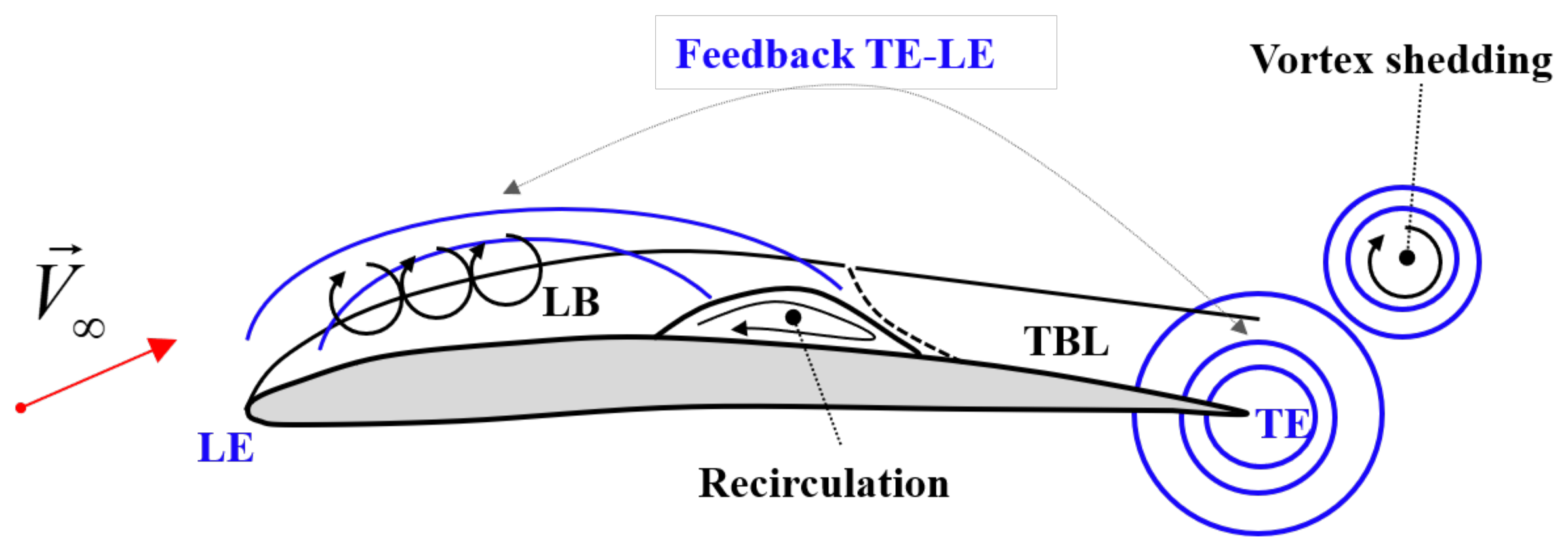
where is the rotational regime, R is the rotor tip radius, is the air density, c is the rotor blade chord and is the air dynamic viscosity. For a full-scale helicopter, a representative is on the order of , while for a UAV, it may range from to . The corresponding tip Mach number are on the order of 0.3. In terms of conventional flat plate aerodynamics, the former Reynolds number explicates in a turbulent flow regime, while the latter explicates in a laminar-transitional flow regime [43,44]. This discrepancy calls into question the applicability of traditional noise prediction tools. When summarizing the different contributions, the literature shows that the main noise sources in a UAV propeller are: tonal self-noise, generated by the volume displacement and aerodynamic loading on the blade; the incoming flow turbulence at the blade leading edge (i.e., LE noise from highly turbulent flow in harsh environments); the interaction of the boundary layer with the blade trailing edge (i.e., TE noise due to turbulent boundary layers but also due to unsteady flow separation of re-circulation bubbles, etc.), flow separation of the flow on the different blade sections (i.e., stall and flow separation noise), blade vortex interaction (i.e., BVI due to the interaction of a rotor blade with the shed tip vortices from a previous blade) and blade wake interaction (BWI, which occurs when the turbulent wake impinges on a subsequent blade) [35,45]. Predicting and reducing the noise radiation from these contributions is even more complicated due to the variety and sensitivity of the noise to the flow field. These reasons clarify the complexity of the problem and the importance of improving knowledge in this field. The relative importance of the noise sources listed here depends significantly on the specific operating conditions [46]. For a schematic representation of the main noise sources involved in these kind of applications, see Figure 1. In the literature, a few studies have been devoted to the analysis of the noise due to the interaction between the propulsive system and the airframe in the case of small propellers. Zawodny et al. [47], in their experimental analysis, found that the presence of airframe surfaces is a not-negligible noise source. In fact, it generates noise levels analogous or even greater than the rotor blade surfaces in particular rotor tip conditions. This study analyzed the effects of both airframe to rotor distance and airframe size. Results show prominent tonal peaks in the Fourier domain related to airframes in the case of close proximity between the airframe and the rotor plane. This effect seems to decay rapidly if the rotor-airframe distance increases. Even the airframe shape seems to influence noise generation. Generic constant cross-section systems were found not to affect noise generation in the plane of the rotor. Instead, a conical airframe shows an increase in the tonal noise component. The present manuscript is organized as follows. In Section 2.1 there is a brief explanation of the most important noise sources for rotors. Section 2.2 reviews the state of art of passive control strategies currently in use. Finally, Section 3 draws conclusions and provides a brief overview of future configurations.
2. Materials and Methods
2.1. Noise Modelling: Tonal and Broad-Band
The aerodynamic noise of conventional propellers can be split into two main components in the Fourier domain: tonal (or narrow-band) and broadband contributions [35,48]. For this reason, research studies tend to separate pressure fluctuations, denoted as , radiated from the blade surface in the far field, into two components [35,48,49]:
where is the tonal component of pressure fluctuations, and is the broadband counterpart. Tonal components are directly related to the periodic motion of the blade in the surrounding fluid. Therefore, the frequency and magnitude of the radiated noise is related to the rotational velocity. The physical mechanism associated with the production of the tonal contributions is related to blade thickness and to aerodynamic loading. On the other hand, broadband noise is radiated by the interaction of turbulent flow structures with the blade edge. Therefore, it is either generated at the blade leading/trailing edge or at the blade tip. The theoretical prediction of the periodic noise generated by propellers is based on the solution of the Ffowcs, Williams and Hawkings non-homogeneous wave equation, known as the Ffowcs–Williams/Hawkings equation [36,50].
where:
- a is the speed of sound;
- is the perturbation on the static pressure;
- t is the observer time;
- are the components of the position vector;
- are the components of the Lighthill stress tensor;
- is the air density;
- is the components of the source velocity vector;
- is Kronecker’s delta function;
- f is a function that defines the surface of the body producing the pressure wave;
- are the components of the generalized stress tensor.
In this equation, there are 3 forcing terms on the right-hand side, which are related to vortex, thickness and loading, respectively. For thin blades and low Mach numbers (), the vortex term is negligible, and the narrow band contribution is given by the sum of a sound source related to blade thickness and one related to aerodynamic loading as the distributed force over the blade. Since it is possible to further decompose , we obtain:
The thickness term takes into account the fluid displacement due to the body, while the loading counterpart takes count of the unsteady force distribution over the body surface. A numerical evaluation of these two quantities can be achieved by discretizing the blade in N finite elements along the span. The resulting overall radiation field can be approximated as the sum of N pointwise sources.
Using a reference system of coordinates , as defined in Figure 2, the two components can be calculated using Equations (7) and (8) (see [35]), which are derived in [48,51]:
where:
- is the position vector of an observer relative to the k-point noise source ,;
- is the aerodynamic force on the k-point blade element of volume ;
- is a scalar magnitude that represents the component of the Mach vector on .
Figure 2.
Representation of the reference coordinate system considered for the definition of the aeroacoustic model.
Figure 2.
Representation of the reference coordinate system considered for the definition of the aeroacoustic model.

If t is time as measured in the observer’s reference frame, retarded time indicates the time when the pressure wave left the noise source. Observer time t and retarded time are connected by:
In Equation (7), the first term represents the far field, while the second is representative of near-field contribution. These two terms differ by the power of in the denominator. The far-field term is proportional to , while the near field term is proportional to ; thus the last term becomes relatively small at large distances from the noise sources [36]. On the other hand, the broadband noise of a propeller is generally produced by three main sources: noise related to the turbulence of the incoming flow (LE noise), noise produced by the interaction of the turbulent boundary layer over the blade surface with the trailing edge (TE noise), and noise generated by the possible separation of the flow (Separation noise) [35]. Therefore, the broadband contribution can be further split as:
where is the TE component, is the LE counterpart and is the separation term. Several authors have addressed the prediction of trailing-edge broadband noise in literature. See, among many studies, Sinibaldi et al. [35], where a relationship for calculating the power spectral density at the trailing edge is reported:
where c is the chord, is the spanwise length of the blade, I is the radiation integral function, B is the number of the blades, is the angular frequency, f is the rotational frequency, is the directivity function and is the wall power spectral density of the pressure fluctuations. The wall pressure spectral density and the spanwise correlation length can be evaluated experimentally or numerically. There are different models for estimation, e.g., the one proposed by Schklinker and Amiet [52], or the more recent model proposed by Rozenberg et al. [53], which takes into account the effect of the adverse pressure gradient. On the other hand, for evaluation. the most used model is the Corcos’ model [54]. The effect of the flow separation on broadband noise can be significant as well. According to [40], an estimation of the power spectral density related to that source is provided by the following expression:
where is the drag coefficient, is the body cross-sectional area where separation is localized, and U is the velocity of the flow.
2.2. Noise Reduction Strategies
As pointed out in the previous sections, propeller noise is a central and complicated issue that has to be taken into account in the design process. This section describes the most effective noise control techniques that can be found in the literature, especially the physical mechanism that enables noise reduction and the changes in aerodynamic performance induced by the noise control system itself. There are two basic strategies to control the noise generated: active and passive. Large-scale airfoils and propellers have employed active flow control methods, but these solutions require energy expenditure. These methods include active modifications of airfoil geometry or of flow conditions, which is achieved by either modifying airfoil geometry and surface through actuators or by acting on the local boundary layer through blowing and suction jets. Due to the typical sizes of the control systems and of the actuators, these technologies are not suitable for small-scale propellers employed by MAVs [55]. These solutions are mostly used on large drones that produce high noise levels. These methods include: (i) a synchrophaser, (ii) speakers in a circular arrangement placed around the propeller, and (iii) small magnets vibrating in an electromagnetic field produced by the coil in the propeller frame [56]. On the other hand, passive flow control techniques enable the boundary layer to be manipulated without further consumption of additional energy, and this can be employed to reduce noise generation. For this reason, there have been several studies on them in the last decade [55]. Consequently, in this paper, the focus is on the second typology of control. The passive control methods employed to reduce noise generation include serrations, applications of porous materials, boundary layer tripping and geometry optimization. The use of serrations is of particular interest in this work due to its potential noise reduction efficiency.
2.2.1. Optimized Geometry
Generally, the aim of the propeller design process is to find the best aerodynamic performance without considering aeroacoustic behaviour. This could be achieved by means of an optimization-based design process. Optimization theory points out that an optimal design problem can be described mathematically by looking for a configuration that minimizes (or maximizes) a certain cost function J that embodies the design objective [36]. For rotors, most of the existing methods are based on the work of Betz [57] from 1919. This approach focuses on finding the optimal propeller geometry in order to minimize the power required to obtain a certain propulsive force (or to maximize the thrust produced by a certain power) at a certain specific operating condition (which has to be interpreted as a combination of airspeed, altitude, and propeller rotational speed). To design a quiet propeller, acoustic requirements must be included, and an iterative process is commonly employed. First, the optimal propeller in aerodynamic terms is defined (i.e., with maximum efficiency). Then, the resulting propeller is further modified in order to improve its acoustic properties [48,58,59]. This is the “classical” procedure for quiet propeller design, but such an iterative process presents some complications. It does not ensure an optimal final design, and it is also difficult to introduce additional constraints into this serial design process, such as side or structural constraints. An improvement of this process is to implement a multidisciplinary design optimization (MDO) approach [60,61]. MDO ensures that all the different disciplines are addressed simultaneously. In this case of study, aerodynamic, structural and acoustic problems were analysed at the same time.
One of the most interesting MDO models in the literature was presented by Gur and Rosen [32,36,62,63] and developed to reach the best compromise between the opposite requirements of efficiency and quietness. In particular, the target of this design process was first to mitigate the tonal component of the noise, dependent on the actual loading of the blade (as seen in Section 2.1). In [36], the cost function J was based on the sound pressure level (). However, the presence of power and stress constraints were taken into account. The first step was to optimize only the acoustic footprint of the blade, and MDO results provided for a blade with a very large chord and relatively small radius. This is, of course, unfeasible in a small rotor due to the power required by such a non-optimal aerodynamic design in combination with the noise increase from the electric engine to deliver such power at the hub. Furthermore, a limit on the extracted power from the battery produces a significant increase in propeller noise. Instead, stress constraints lead to an increase in cross-sectional thickness and rotational speed. These results clarified the need for a multidisciplinary optimization. In fact, the presence of both structural and acoustic constrains is fundamental to achieve feasible results.
This model was enhanced in [32], where the propeller design model was extended to the entire propulsion system. In other words, a model for electric motor and battery was added to the previous model. For this purpose, theoretical models of these components were required. The models presented were based on a comprehensive investigation of existing motors and batteries. The performance of the vehicle greatly depends on the interaction between propeller, electric motor and battery. Clearly, then, it is important to study these three components contemporaneously.
By using the Gur and Rosen model [36], Sinibaldi and Marino [35] employed a quiet propeller and carried out an experimental analysis to characterize its behaviour as compared to a conventional one (conventional in the sense of a propeller not specifically designed to achieve noise reduction). In their study, the focus was on the optimization of the chord distribution along the span-wise direction. The results of the comparison of the two propeller showed that, by using the MDO approach, significant noise reduction can be achieved, at least for the narrow-band contribution. An unexpected result is that by increasing rotational velocity in order to achieve high thrust values, strong vibrations occur that can be ascribed to the increased thickness of the optimized blade. This phenomenon produces noise that make the optimized propeller comparable to the conventional one.
Furthermore, Serrè et al. [21,22,38] presented a model for reducing the noise of a MAV rotor while preserving the endurance. The aim was to develop an optimisation algorithm that is applicable in the industrial field, especially in terms of computational cost. The method was based on low-order computational tools for the estimantion of the aerodynamic loading and the tonal and braodnband noise. These tools were coupled with the optimization algorithm in order to define a law for chord and twist distributions of the blade. A relevant reduction of 8 dB(A) was measured. Results showed that the optimized propeller had a higher aerodynamic efficiency. Such an effect permits to reduce the rotational speed resulting in a lower main frequency of the tonal noise, a lower intensity of the small turbulent eddies (which are related to high frequencies of ingestion noise) and a lower tip Mach number (which implies a lower intensity of the radiated noise).
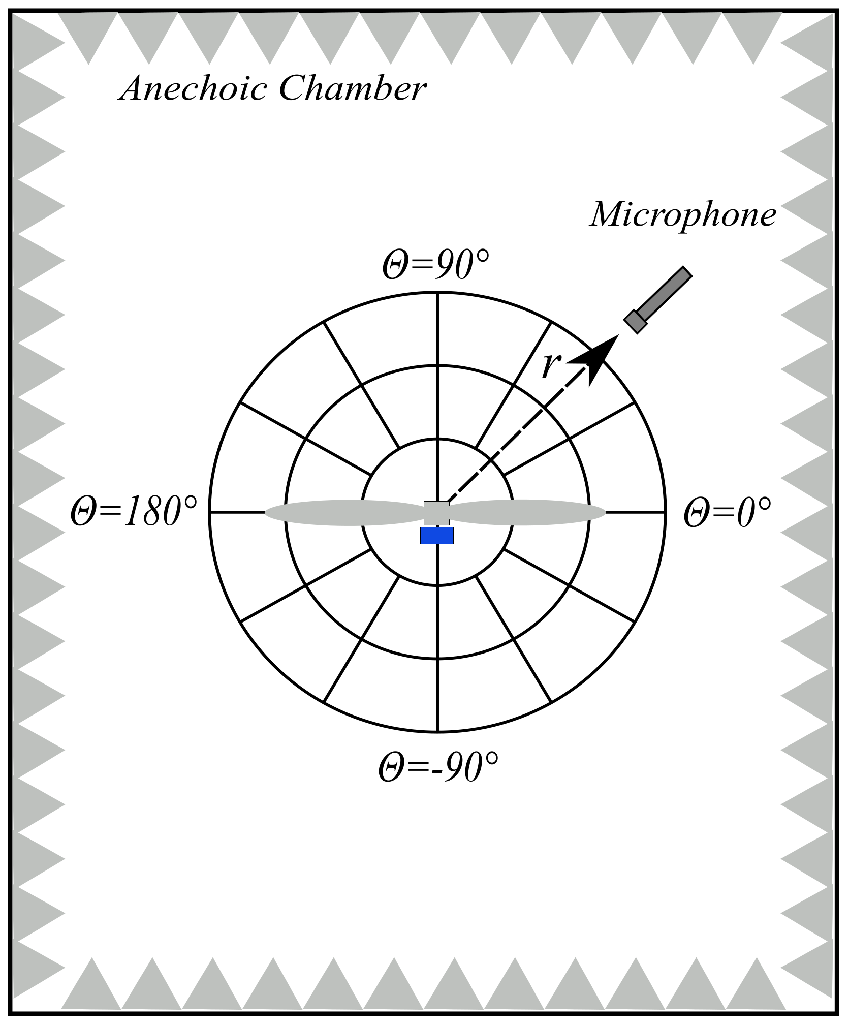
Moreover, Pagliaroli et al. [34] used an MDO approach in order to assess the effect of the pitch angle on MAV noise signatures. An experimental analysis was carried out in order to evaluate aeroacoustic behaviour. The experimental tests were carried out on a propeller of 2 [mm] with a twist angle of zero. The blades were mounted on a collective pitch in order to vary the pitch angle from 0 to 21 [deg]. All the measurements were taken at the anechoic chamber of the Office National d’Études et de Recherches Aérospatiales (ONERA). The optimization strategy seemed to be useful in reducing the number of variables in the multiphysics problem. Furthermore, wall pressure measurements confirmed that the pressure signature was dominated by the broadband component generated by the separation bubble, showing that it is important to extend studies to broadband noise.
Wisnieski et al. [64] developed a propeller design program in order to construct quiet propellers with improved efficiency. This approach enabled to design a propeller, evaluate its performance and, finally, to create a 3D model for additive manufacturing. Such an optimization approach lead to an high pitch propeller with low aspect ratio, reducing the chord length this propeller has a larger surface which guarantee the desidered thrust at lower rotational speed. The obtained propeller was characterized by 5 blades with an oval tip, which proved to be 12 dB quieter than the stock commercial DJI phantom II propeller and 6% more aerodinamically efficient. This investigation put emphasis on tip geometry as a powerful strategy to reduce noise. In the context of propeller shape optimisation, it is also interesting to consider optimal propeller blade spacing as in the study of Cattanei et al. [65]. This study presents a general optimization strategy based on the evaluation of the rotor interference function, which may be applied to rotors of arbitrary blade number. By imposing unequal spacing between the blades, it is possible to reduce the tonal noise component without having any effect on thrust generation. Based on their results, a propeller has been realized and tested in semi-anechoic chamber to validate the interference model. The experimental results show a good agreement, confirming that the proposed algorithm is reliable for the design of a propeller.
2.2.2. Serrated Trailing Edge
In the literature, one of the most interesting and investigated noise control strategies is based on the application of serrated trailing edges (STE). Serrations applied to the TE of an airfoil reduce noise generation due to the destructive interference of the pressure fluctuations produced by the flow structures convecting along the slanted edge. This technique is already employed on wind turbine blades and fixed-wing airfoils. Nevertheless, there have been a few studies on the application of serrations to small rotors. Figure 3b shows a representation of a blade with the serration at the TE in comparison with the baseline propeller blade (Figure 3a) (baseline has to be intended as a propeller without any geometric modification).
The idea for this control strategy was inspired by nature, in particular by the silent flight of owls [66,67,68]. Owls are known to be one of the most silent predators in nature. The quietness of their flight is due to their characteristic wings, with three main physical features: (i) a suction wing surface with a soft downy coating, (ii) a comb of stiff feathers at the wing leading edge, and (iii) TE feathers and wings with a fringe of flexible filaments. The sawtooth pattern employed by manufacturers is the simplest geometric way to mimic the permeability of owls’ wings.
Chong et al. [69] and Avallone et al. [70] focused on wind turbine applications. The first study involved an experimental analysis on a flat plate, while the second was a numerical investigation on an airfoil at zero-degree angles of attack by resolving the Ffowcs–Williams/Hawkings analogy (see Section 2.1). On the basis of Howe [71], Chong et al., pointed out that significant noise reduction can be achieved if two conditions are met. The first is that the serration length is of the same order of the turbulent boundary layer thickness near the TE. The second is that the serration angle (called in Figure 4) is small, favouring sharp sawtooths. Howe’s theoretical approach states that the introduction of obliqueness at the TE will reduce the coherence between the acoustic sources along the wetted surface. This effect will result in weaker noise emission. The experimental acoustic results show that TE broadband noise can be significantly reduced by using serration. Furthermore, noise reduction has been found to occur in a large range of frequencies. In [69], hot wire anemometry (HWA) measurements were aimed at determining coherent structures on a flat plate surface. The measurements showed that wake structures are affected by serration since noise reduction can be ascribed to this phenomenon. On the other hand, Avallone et al. [70] investigated the physical noise reduction mechanism by means of a numerical simulation based on lattice Boltzmann and Ffowcs–Williams/Hawkings equations (see Section 2.1). The propeller analysed is a “conventional” sawtooth and a combed-sawtooth TE. For the combed-sawtooth geometry, the space between the teeth was filled with solid filaments called combs (see Figure 4). Noise reduction was found to depend on frequency. Once a critical value was reached, corresponding to ( is the Strouhal number based on the airfoil chord and the free-stream velocity), no noise reduction was observed. For a given serration geometry, the introduction of combs does not modify the frequency range over which noise reduction can be observed but only the maximum noise reduction. Flow fields analysis shows that the introduction of sawtooth serrations promotes the constitution of elongated coherent structures in the wake in the space between two consecutive teeth, together with hairpin vortices along the sawtooth edges. The effect of this modification on the time-averaged flow field is to mitigate both the outer (namely from the centre line toward the edge) and the inner (namely from the edge toward the centre line) flow motions.
Pang et al. [55] conducted an experimental analysis of the effect of pitch angle and trailing edge serration on a small rotor. Results showed that sawtooth serrations employed at the TE can noticeably suppress broadband noise in the high frequency region in the far-field. The main drawback observed was that the tonal component seems to increase in the low-frequency region. At low velocities, serrations seem to lead to greater noise reduction. Such an effect suggests that STE is a potential solution for reducing UAV noise when propellers are sure to operate at low speed. Near-field experiments shed light on sound field characteristics, exhibiting a radial decay of SPL in the propeller rotation plane.
Ning et al. [72] also carried out an experimental analysis on STE, the aim being to reduce noise while maintaining the thrust constant. This work defined three parameters that ensure a beneficial employment of serration for noise reduction. The parameters considered were:
- The non-dimensional tooth height, defined as the ratio between the tooth half-height and the boundary layer thickness ;
- The aspect ratio of the tooth, defined as the ratio between the width and the half-height ;
- The boundary layer thickness-based Strouhal number .
The geometrical parameters employed are defined in Figure 5. Ning pointed out that to achieve noise reduction, . Otherwise the amplitude of the serration is too small, and as a result, the turbulent eddies go beyond the sawtooth without significant interaction. Furthermore, the inclination angle (see Figure 4) must be lower than , and this fact is guaranteed by imposing . In the definition of the Strouhal number, f is the sound frequency, is the boundary layer thickness and by having called the relative velocity. This non-dimensional coefficient has to be greater than 1 (as stated in Howe’s theory), which means , in order to obtain a significant noise reduction. Experiments have been carried out at . The results show that when , noise reduction appears at a frequency lower than , while the overall noise level increases. Therefore, this parameter gives the frequency range in which it is possible to find noise reduction. This work analyses four rotors by varying the coefficient. The analysis involves aerodynamic and aeroacoustic measurements to characterize wake flow statistics. The results show that the STE can reduce broadband noise in the high frequency region without any loss in aerodynamic performance, while, in the low frequency region, the noise generated is almost the same. Measurements also show that, in order to keep the thrust constant, a higher rotational velocity of the propeller is required.
Intravartolo et al. [49] alslo carried out an experimental analysis on STE by focusing on the serration depth effect. Results showed that an increase in serration depth produces a reduction in the intensity of the trailing edge wake. Nevertheless, benefits from the depth of the serrations diminished with respect to the overall noise signature of the propeller. When serration depth reaches a value comparable to half of the mean aerodynamic chord (MAC), no further gain in aeroacoustic effect can be observed. On the contrary, an increase in the overall noise may occur due mainly to aerodynamic effects. Serration depth effect was also analysed by Pagliaroli et al. [23,24,25], in particular, as regards broadband noise component and the directivity of the noise source in the near-field. A notable reduction in the noise generated was obtained in the low-frequency region, and damping in the tails of the probability density function (PDF) was observed. The statistical analysis shed light on the physical phenomenon that lies behind the noise reduction. PDF tails are commonly related to intermittent structures in the pressure field; as a result, serrations seem to eliminate strong energetic events. The drawback of serration is a loss in aerodynamic efficiency, so the optimal geometry had to be found. An analysis of the directivity showed that the sawtooth pattern effect is bounded in the polar angle range : (the polar angle considered is defined in Figure 6).
An improvement to STE technology could be made by the employment of fractal trailing edge geometry. Hasheminejad et al. [73] investigated this kind of solution by comparing the behaviours of a sawtooth TE and a conventional TE. An experimental analysis was carried out to test these different TE geometry applied to a flat plate. Noise measurements showed that both the sawtooth and the fractal trailing edge produce a reduction in the broadband noise but an increase in the tonal noise radiated by the tip vortex in the serrations gaps. However, the tonal component seems to be mitigated by the fractal TE. This effect may be ascribed to the cancellation of vortex shedding. The investigation on the coherence behind the TE shows that the fractal geometry interacts with the strong coherent structures that always occur between the tips of the serrated TE by decreasing their strength and extension in all direction. Moreover, the use of sawtooth and fractal-sawtooth TE improved post-stall lift behaviour. Although lift slightly decreased at some pre-stall angles of attack, the drag did not react significantly to TE replacement.
A mathematical and physical interpretation may be given to the effect of the serrated trailing edges on the noise generated by the propeller. In particular, the serration effect creates destructive interference in pressure fluctuations which are convected along the geometry. From a recent investigation, presented in [70,74], it was found that the frequency spectrum and the boundary layer characteristics develop at the serration edge. This means that the assumption of the theory of “frozen turbulence” cannot be used to analyse of the noise reduction performance. Some of the latest studies [70,75] show that changes in the skin-friction coefficient along the serrations are related to the change of the frequency spectrum and could be used to obtain a more accurate prediction of their response.
2.2.3. Leading Edge Serration
The silent flight of owls also inspired another control strategy: serrated leading edge. This technique has rarely been applied on propellers to reduce noise emissions, but it seems very attractive since it enables a noise reduction up to 4 dB with an increase in the thrust generated. Wei et al. [76] investigated propellers with LE serrations of different morphologies and found that SLE propellers could improve the thrust generated. They achieved a gain of almost 3% in comparison with the reference propeller. In addition, they tested the propeller on a real quad-copter and measure a noise reduction of 4.73 dB and 3.79 dB in hovering at 5 and 8 m height, respectively. LE serrations reduce the noise emitted because they work as a vortex generator and can mitigate velocity fluctuations and also modify the laminar-turbulent transition on the propeller suction surface.
In addition, Chaitanya et al. [77,78] performed an experimental analysis regarding the use of leading-edge serration on a flat plate. More in detail, in [78], an optimum geometry for the serration was found; the maximum noise reduction was achieved when the turbulence integral length scale corresponded to half of the serration wavelength. Moreover, in [77], an improvement of serration geometry was reported; specifically, three innovative serration geometry were defined and investigated. These configurations involve: (a) a double-wavelength obtained by adding two components, one of which has twice the frequency of the other; (b) a chopped peak, in which the source at the peak is increased by clipping the peak so that it generates destructive interference with the root source; (c) a slitted root leading edge obtained by adding a narrow slit at the root position. The results show that the main advantages are achieved by means of the double-wavelength serrations even if the other two geometries can lead to a not negligible noise reduction. It is important to emphasise that this control strategy has no effect on aerodynamic performance. Moreover, considering a flat plate, Narayan et al. [79] investigated the noise reduction in the case of sinusoidal serrations. The results showed that by using this geometry, the broadband noise can be significantly reduced, in particular in the mid-frequency range (500 Hz–8 kHz). It was also found that the serration amplitude is the factor that influences the sound emissions more.
A numerical model to investigate the effect of leading edge serration was reported in [80] based on Amiet’s approach, which also makes it valid for high-mach-number applications, where leading edge noise is a common problem. The numerical simulation performed showed that the noise reduction is related to a destructive interference of the scattered pressure induced by the serrations. They also defined geometrical parameters that ensure the noise effect.
Hersh et al. [81] investigated the use of LE serrations on a stationary and rotating NACA 0012 airfoil. They demonstrated that a sensible reduction in tonal noise (approximately between 4 and 8 dB) can be achieved, and it is related to wake vortex shedding at high incidence.
2.2.4. Boundary Layer Tripping System
The experiments of Leslie et al. [39,82] showed that broadband propeller noise emission of a propeller can be reduced by employing a LE boundary layer tripping system on the suction surface of the blade, with negligible evidence of any aerodynamic performance loss. The control technique presented in these works look at a boundary layer tripping system in the form of a simple strip of aluminium adhesive tape. A rendering of the blade with the tripping system is detailed in Figure 3c. The noise reduction mechanism is related to the mitigation of BL noise because of a forced laminar to turbulent transition of the BL. Noise generated by the turbulent boundary layer (TBL) is different from the laminar boundary layer (LBL). The LBL generates strong and loud tonal noise, so it appears as narrow band peaks in the frequency domain. This is the result of an aeroacoustic feedback loop between LBL oscillation and the noise radiated by the TE at the same frequency. Furthermore, the presence of a small laminar separation bubble just prior to the TE helped to amplify the Tollmien–Schlichting (T-S) boundary layer waves, confirming what was found in [83]. In this situation, the presence of the aeroacoustic feedback loop combined with the amplification of the T-S resulted in the production of strong narrow band tones. By forcing the transition from laminar to turbulent through the use of a transition strip, the aeroacoustic feedback loop is broken. The tripping system translates the transition from to of the chord and replaces the tonal noise with a broadband noise radiating from the TE. As a result of transition, due either to the presence of a laminar separation bubble or to forced transition through the use of a transition strip, a TBL is present at the TE of the airfoil. TBL-TE is strongly dependent upon the BL thickness at the TE. The location of the transition affects the TBL-TE noise. If the transition occurs further downstream along the chord, there are smaller contributions from low frequencies and increased high-frequency contributions. Consequently, the tonal noise connected with these two phenomena seems to be mitigated. This passive control technique seems very interesting because it should not affect the aerodynamic properties of the propeller, but rather reduce the drag force.
2.2.5. Porous Material Inserts
The idea of using porous materials to obtain noise attenuation dates back to the studies of Graham [84] on the silent flight of the owl. Since then, porous materials have been added to the blade leading edge in order to reduce noise generation due to strong blade vortex interactions (BVI) in helicopter applications [85]. Another solution is to treat the flap side-edge of the wing with porous material in order to mitigate flap-noise [86]. Recently, porous material has been tested on blunt bodies, such as the cylinder [87], and on flat plates to see if it is possible to reduce noise emissions by using them. Another approach previously discussed in the literature is the usage of a fully porous airfoil [88,89]. These airfoils have a prevalently rough surface. Thus, the drag force generated is expected to increase while the lift force is expected to decrease with respect to the baseline airfoil. Nevertheless, aerodynamic measurements [89] show that there is more lift and less drag as porous material flow resistivity increases. Such a simple dependence cannot be found for the acoustic properties. On the other hand, Geyer et al. [88] found that the SPL generated at the TE of the porous airfoil was lower with regard to the baseline airfoil for a large range of medium frequencies. Instead, for very high frequency, the porous airfoil has a higher noise signature than the non-porous one. As expected, a TBL analysis shows that the porous airfoil has a boundary layer thickness and a displacement thickness that exceed the non-porous one in both the suction and pressure side of the airfoil. In recent years, additive manufacturing technology (i.e., 3D printing) has grown very quickly and has now made it possible to directly integrate porous material structures into airfoils and rotor blades. Jiang et al. [90] carried out an experimental analysis on the effect on the TE noise of porosity employed on a rotor rig. Porous materials have already been used to control flat plate noise generation [68,69,91]. In this work, instead, the focus was on a modified propeller with the insertion of a blade extension realized by additive manufacturing. This technology allows designers to employ complex geometries at the TE in order to develop a quiet propeller. The way to attain acoustic stealth is to disrupt the conversion of TBL pressure fluctuations into acoustic waves and reduce the turbulent length scales in the BL without generating higher levels of turbulence (noise) at unwanted frequencies. Two sets of experiments and one numerical simulation were performed. The first set of experiments involved measuring the acoustic impedance of various additively manufactured samples in order to understand the porous structures’ effect on absorption. After this characterization, the porous structures were applied as blade extensions to the outer part of the rotor blade without increasing the rotor diameter. Figure 7 shows a schematic representation of the blade extension. The experimental results are very interesting, indicating significant noise reduction in the frequency region of (1:7) kHz. Numerical simulation showed that the porous TE did not affect the flow field or the BL thickness at the TE. Consequently, the noise reduction observed in the rotor tests may be attributed more to a reduction in turbulence length scale than a disruption of the edge scattering process.
In the literature, several authors have studied the effect of porosity on trailing edge noise [92,93,94]. Rubio Carpio et al. [92] focused on a flat plate with different types of inserts. The porous inserts, covering of the chord, are manufactured with metal foams of cell diameters (m) and (m) and permeability values of and . The far-field measurements show low-frequency noise attenuation of up to 7 and , respectively, for the first and second permeability value. On the other hand, in the high-frequency region, an increase in noise up to 8–10 dB was observed. This phenomenon is due to surface roughness. Increasing permeability also led to a reduction of the frequency range affected by noise attenuation. A PIV measurement campaign shows an increase in BL thickness and in displacement thickness for the metal foam insert with higher permeability. Analysis in the Fourier domain shows that the attenuation in velocity fluctuations affects mostly the low-frequency region, suggesting that turbulence intensity reduction may be one of the changes that contributes to noise reduction. On the other hand, the results do not show an increase in high-frequency fluctuation content as regards the solid case. Showkat Ali et al. [93] demonstrated that porous TE can delay vortex shedding and significantly increase vortex formation length, leading to a very low turbulent near-wake region. The usage of porous material also leads to significant lateral coherence reduction of the turbulent structure.
Ref. [94] documents acoustic test on an airfoil with porous treatment at the TE. Maximum noise reduction reached was up to 2–6 dB. This effect may be attributed to a material-dependent pressure field generated in the near-field related to the flow resistivity of the TE material.
A very interesting control technique is the use of Poro-Serrated TE [95,96,97], which combines the serrated TE (Section 2.2.2) and the effect of porosity. These poro-serrated TE devices contain porous materials of various air flow resistances at the gaps between adjacent members of the serrated sawtooth. The object of this study was to understand if two control strategies for noise mitigation can co-exist, one related to the oblique edges introduced by the serrations, the second arising from porosity, which allows the pressure side and suction side to communicate, thereby reducing the acoustic dipole strength at the trailing edge. In these studies, the focus was on a flat plate with a serrated trailing edge with the addition of porous foam between adjacent members of the sawtooth. The porous foam was cut in order to match perfectly with the volume and shape of the sawtooth gaps, thus preserving the original airfoil profile. This technique can simultaneously suppress vortex shedding and reduce broadband noise. Results showed that multiple broadband noise reduction mechanisms occur (serration + porous material), but it is likely that the porous material is enhancing the serration effect, rather than the porous material exerting an effect of its own.
2.2.6. Metamaterials
One way of achieving sound attenuation is the application of a sound barrier that reflects or absorbs the incident acoustic energy. Such a solution cannot be directly applied on MAVs because it eliminates the passage of air. To be employed on a rotor blade, it is important to guarantee permeability to air by designing a ducted propeller. In recent years, there has been a fast growth in metamaterial science, leading to new solutions for manipulating acoustic energy. Metamaterials are composed of subwavelength structures since their effective acoustic properties are governed by their structural shape rather than their constitutive properties.
Ghaffarivardavagh et al. [98] presented a design methodology for an ultra-open metamaterial (UOM) composed of subwavelength unit-cell structures featuring a predominately open area. The designed UOM works as a high-performance selective sound silencer for applications where both sound attenuation and highly efficient ventilation are required. The proposed method is based on Fano-like interference [99] for selective attenuation of acoustic waves. The first part of their studies aimed to analytically demonstrate that Fano-like interference is present in a transverse bilayer metamaterial. Then, the feasibility of the metamaterial structure was proved by providing both analytic and experimental validation. The designed UOM consist of two distinguishable regions: a central open part and a peripheral helical part. The two regions are characterized by different acoustic properties. Figure 8 reports a 3D representation of it. The contrast in the acoustic properties of the two regions has been proved to be essential to achieve the required silencing functionality. The experimental tests show a reduction in transmitted acoustic energy of up to . Another interesting feature of this solution is that the design is inherently flexible. Desired acoustic and refractive index impedance can be achieved by adjusting some geometrical parameters. This feature gives the designer a large number of degrees of freedom in order to optimize device performance.
2.2.7. Bio-Inspired Blade Shape
An innovative bio-inspired UAV propeller was investigated in [100]. The authors took inspiration from nature and designed a propeller with a planform shape based on cicada wings and maple seeds (see Figure 9b). In order to compare it to a conventional propeller (Figure 9a), the designed propeller was given the same planform area, the same cross-sectional shape and same weight. Both the propellers were realized by using additive manufacturing. An experimental analysis was carried out in order to characterize the aerodynamic and aerocoustic behaviour of the propellers. The aerodynamic measurements showed that the bio-inspired propeller can provide the same thrust as the baseline propeller under the same power input when hovering, but the rotational regime was lower, indicating a higher lift coefficient for the bio-inspired blade. However, the reduction in noise was up to 4 dB and can be ascribed to the small force variation of the new blade. Thrust standard deviation , representative of force oscillation, was observed to be lower with respect to the baseline propeller. As seen in Section 2.1, loading noise is related to force variation. Furthermore, the bio-inspired propeller generated a smaller wake region and demonstrated a faster decay rate in tip vortex strength.
Another noise reduction strategy inspired by nature is presented in [101]: mimicking the downy coat of the barn owl to reduce the noise generated by an airfoil. A numerical investigation was carried out on an airfoil with finlet fences. The simulation was carried out on a baseline geometry, and later, the finlets were added. The study was performed by using an implicit large eddy model. The comparison between lift, drag and pressure coefficients for the baseline and the owl-inspired geometry shows that the add-on does not significantly degrade the aerodynamic performance. Furthermore, spectral analysis shows a slight reduction in pressure spectra at high frequencies near the TE of the airfoil. At the present state-of-art, this technology has not been tested on a propeller, so it would be interesting to investigate this innovative geometry both numerical and experimental in order to understand if it is really applicable to drone propellers.
Finally, Noda et al. [102] developed a new quiet propeller inspired by owl wing morphologies. A DJI Phanton 3 propeller was employed as the reference propeller, and different structures were attached to the trailing edge of the propeller. The main interesting results came from an aluminium plate attached at the trailing edge. The first step in order to reduce sound emissions was to employ a greater propeller. The strategy herein proposed showed a reduction in noise of almost 2 dB with no effect on the power consumption. This effect could be related to the reduction in the rotational speed, while the rotational speed to maintain a certain operating condition will be lower with a smaller radius propeller.
2.2.8. Active Control Strategy: Synchrophaser
In order to give a complete review of the noise reduction strategies, in this section, an example of one of the most effective active control strategy is reported. A synchrophaser is a device that fixes the rotational velocity and the phase angle between the propellers [56]. This is achieved by comparing the relative position between the propellers and setting a specific angle between the blades [103,104,105]. Such a system can be used to control noise by creating destructive interference between the sound waves released by the two propellers. It is important to emphasise that the synchrophaser can also be used between more than two propellers, which makes it very interesting in applications for large drones or distributed electric propulsion in aircraft.
3. Conclusions
This paper focuses on the noise generated by small rotors, the aim being to identify which passive noise control strategies can be employed on a drone propeller. The main noise sources for this application concern the interaction between the BL and the TE of the blade. This paper presents several strategies to control this noise source. Even though noise control is the main focus, aerodynamic performance is also taken in count in order to guarantee the success of the mission.
The first strategy to reduce noise emission was to employ an optimized geometry by taking into account acoustic constraints in the multi-disciplinary optimization process. These solutions led to a blade geometry that reduces noise for a specific operating configuration, so it is not sure that in other configurations, the behaviour would be exactly the same, both in terms of thrust and noise generation. The effect of chord distribution and of pitch angle were analyzed, indicating significant noise reduction, but the drawback was a loss of aerodynamic features.
By taking ideas from nature, in particular the owl wing, innovative blade geometries may be employed, with the most effective, seemingly, being the application of serration. The most investigated configuration is the sawtooth pattern at the TE, which has been shown to reduce the broadband noise component. From a theoretical point of view, this effect can be related to a reduction in coherent structures in the pressure field. This assumption is confirmed by statistical analysis, which shows lower PDF tails when serration is employed at the TE. Another configuration involves the use of fractal serration, with the effect, even for this configuration, being related to the interaction between the coherent structures and the serration.
Serrations can also be employed at the leading edge. Through this technology, it seems possible to achieve a significant reduction in noise and also an improvement in aerodynamic performance. Leading-edge serrations act as vortex generators, limiting velocity fluctuations and anticipating the laminar-turbulent transition of the boundary layer; such effects result in noise reduction.
Another strategy to reduce TE noise is the use of porous materials. The effect of porosity on rotor noise has been studied principally for wind turbines but could be interesting for UAV rotors as well. In fact, it has been proved that porosity produces a reduction in turbulence length scale. The next step is to employ this technology on a small-scale propeller and test it. Furthermore, metamaterials can be designed as highly efficient sound barriers for a target frequency. The development in metamaterials science may, in a few years, lead to the realization of a ducted propeller with specific sound characteristics.
On the other hand, in order to reduce the tonal noise component, a boundary layer tripping system can be applied on the suction side of the propeller blade in the form of a simple adhesive aluminium strip. By using this system, laminar to turbulent transition is forced at of the chord. This effect results in broadband noise radiating from the TE in the high-frequency region and seems to have no effect on thrust generation; rather, it should reduce drag force since the efficiency of the propeller should increase.
Finally, this paper presented an innovative type of geometry inspired by nature. This particular geometry mimics the planform shape of cicada wings and maple seeds [100]. The experimental results show that this bio-inspired wing can provide the same thrust as a baseline propeller. Additionally, a reduction in loading noise was observed and can be attributed to the reduction in standard thrust deviation.
Author Contributions
Investigation, Formal Analysis and Writing, P.C.; Investigation and Writing, D.R.; Conceptualization and Writing, T.P. All authors have read and agreed to the published version of the manuscript.
Funding
This research received no external funding.
Institutional Review Board Statement
Not applicable.
Informed Consent Statement
Not applicable.
Data Availability Statement
Not applicable.
Conflicts of Interest
The authors declare no conflict of interest.
Abbreviations
The following abbreviations are used in this manuscript:
| MAV | Micro Aerial Vehicles |
| UAV | Unmanned Aerial Vehicle |
| UAS | Unmanned Aerial System |
| MDO | Multi Disciplinary optimization |
| STE | Serrated Trailing Edge |
| TE | Trailing Edge |
| LE | Leading Edge |
| TBL | Turbulent Boundary Layer |
| LBL | Laminar Boundary Layer |
| UOM | Ultra-Open Metamaterial |
References
- Floreano, D.; Wood, R.J. Science, technology and the future of small autonomous drones. Nature 2015, 521, 460–466. [Google Scholar] [CrossRef] [PubMed]
- Figliozzi, M. Lifecycle modeling and assessment of unmanned aerial vehicles (Drones) CO2e emissions. Transp. Res. Part D Transp. Environ. 2017, 57, 251–261. [Google Scholar] [CrossRef]
- Yoo, W.; Yu, E.; Jung, J. Drone delivery: Factors affecting the public’s attitude and intention to adopt. Telemat. Inform. 2018, 35, 1687–1700. [Google Scholar] [CrossRef]
- Koiwanit, J. Analysis of environmental impacts of drone delivery on an online shopping system. Adv. Clim. Change Res. 2018, 9, 201–207. [Google Scholar] [CrossRef]
- Goodchild, A.; Toy, J. Delivery by drone: An evaluation of unmanned aerial vehicle technology in reducing CO2 emissions in the delivery service industry. Transp. Res. Part D Transp. Environ. 2018, 61, 58–67. [Google Scholar] [CrossRef]
- EASA. Introduction of a Regulatory Framework for the Operation of Unmanned Aircraft Systems in the ‘Open’ and ‘Specific’ Categories; Opinion No 01/2018; EASA: Nairobi, Kenya, 2018.
- Cherney, M. Delivery Drones Cheer Shoppers, Annoy Neighbors, Scare Dogs. The Wall Street Journal, 26 December 2018. [Google Scholar]
- Torija, A.J.; Li, Z.; Self, R.H. Effects of a hovering unmanned aerial vehicle on urban soundscapes perception. Transp. Res. Part Transp. Environ. 2020, 78, 102195. [Google Scholar] [CrossRef]
- Morrell, S.; Taylor, R.; Lyle, D. A review of health effects of aircraft noise. Aust. N. Z. J. Public Health 1997, 21, 221–236. [Google Scholar] [CrossRef]
- Kapustina, L.; Izakova, N.; Makovkina, E.; Khmelkov, M. The global drone market: Main development trends. In Proceedings of the SHS Web of Conferences, EDP Sciences, Muscat, Oman, 15–16 November 2021; Volume 129, p. 11004. [Google Scholar]
- Schäffer, B.; Pieren, R.; Heutschi, K.; Wunderli, J.M.; Becker, S. Drone Noise Emission Characteristics and Noise Effects on Humans—A Systematic Review. Int. J. Environ. Res. Public Health 2021, 18, 5940. [Google Scholar] [CrossRef]
- FAA. FAA Aerospace Forecast, Fiscal Years 2019–2039; Technical Report; FAA: Washington, DC, USA, 2022.
- Mulero-Pázmány, M.; Jenni-Eiermann, S.; Strebel, N.; Sattler, T.; Negro, J.; Tablado, Z. Unmanned aircraft systems as a new source of disturbance for wildlife: A systematic review. PLoS ONE 2017, 12, e0178448. [Google Scholar] [CrossRef] [PubMed]
- Ditmer, M.; Vincent, J.; Werden, L.; Tanner, J.; Laske, T.; Iaizzo, P.; Garshelis, D.; Fieberg, J. Bears Show a Physiological but Limited Behavioral Response to Unmanned Aerial Vehicles. Curr. Biol. 2015, 25, 2278–2283. [Google Scholar] [CrossRef] [PubMed]
- Christiansen, F.; Rojano-Doñate, L.; Madsen, P.; Bejder, L. Noise Levels of Multi-Rotor Unmanned Aerial Vehicles with Implications for Potential Underwater Impacts on Marine Mammals. Front. Mar. Sci. 2016, 3, 277. [Google Scholar] [CrossRef]
- Smith, C.; Sykora-bodie, S.; Bloodworth, B.; Pack, S.; Spradlin, T.; Leboeuf, N. Assessment of known impacts of unmanned aerial systems (UAS) on marine mammals: Data gaps and recommendations for researchers in the United States. J. Unmanned Veh. Syst. 2016, 14, 31–44. [Google Scholar] [CrossRef]
- Christian, A.; Cabell, R. Initial investigation into the psychoacoustic properties of small unmanned aerial system noise. In Proceedings of the 23rd AIAA/CEAS Aeroacoustics Conference, Denver, CO, USA, 5–9 June 2017; p. 4051. [Google Scholar]
- ANSI. Standardization Roadmap for Unmanned Aircraft Systems, Version 2.0., Prepared by the ANSI Unmanned Aircraft Systems Standardization Collaborative (UASSC): June 2020; Technical Report; American National Standards Institute: New York, NY, USA, 2020. [Google Scholar]
- Eißfeldt, H.; Vogelpohl, V.; Stolz, M.; Papenfuß, A.; Biella, M.; Belz, J.; Kügler, D. The acceptance of civil drones in Germany. CEAS Aeronaut. J. 2020, 11, 665–676. [Google Scholar] [CrossRef]
- ICAO. Cir 328 AN/190, Unmanned Aircraft Systems (UAS) Circular 328; Technical Report; International Civil Aviation Organization (ICAO): Montreal, QC, Canada, 2011. [Google Scholar]
- Serré, R.; Gourdain, N.; Jardin, T.; Jacob, M.C.; Moschetta, J. Towards silent micro-air vehicles: Optimization of a low Reynolds number rotor in hover. Int. J. Aeroacoustics 2019, 18, 690–710. [Google Scholar] [CrossRef]
- Serré, R.; Fournier, H.; Moschetta, J. A design methodology for quiet and long endurance MAV rotors. Int. J. Micro Air Veh. 2019, 11, 1756829319845937. [Google Scholar] [CrossRef]
- Pagliaroli, T.; Candeloro, P.; Camussi, R.; Giannini, O.; Panciroli, R.; Bella, G. Aeroacoustic Study of small scale Rotors for mini Drone Propulsion: Serrated Trailing Edge Effect. In Proceedings of the 2018 AIAA/CEAS Aeroacoustics Conference 2018, Atlanta, GA, USA, 25–29 June 2018. [Google Scholar] [CrossRef]
- Candeloro, P.; Nargi, R.; Patanè, F.; Pagliaroli, T. Experimental Analysis of Small-Scale Rotors with Serrated Trailing Edge for Quiet Drone Propulsion Experimental Analysis of Small-Scale Rotors with Serrated Trailing Edge for Quiet Drone Propulsion. J. Phys. 2020, 1589, 012007. [Google Scholar] [CrossRef]
- Candeloro, P.; Nargi, R.E.; Grande, E.; Ragni, D.; Pagliaroli, T. Experimental Fluid Dynamic Characterization of Serrated Rotors for Drone Propulsion. J. Phys. Conf. Ser. 2021, 1977, 012007. [Google Scholar] [CrossRef]
- Deters, R.; Ananda Krishnan, G.; Selig, M. Reynolds number effects on the performance of small-scale propellers. In Proceedings of the 32nd AIAA Applied Aerodynamics Conference, Atlanta, GA, USA, 16–20 June 2014; p. 2151. [Google Scholar]
- Deters, R.; Kleinke, S.; Selig, M. Static testing of propulsion elements for small multirotor unmanned aerial vehicles. In Proceedings of the 35th AIAA Applied Aerodynamics Conference, Denver, CO, USA, 5–9 June 2017; p. 3743. [Google Scholar]
- Deters, R.; Dantsker, O.; Kleinke, S.; Norman, N.; Selig, M. Static performance results of propellers used on nano, micro, and mini quadrotors. In Proceedings of the 2018 Applied Aerodynamics Conference, Atlanta, GA, USA, 25–29 June 2018; p. 4122. [Google Scholar]
- Merchant, M.; Miller, L.S. Propeller performance measurement for low Reynolds number UAV applications. In Proceedings of the 44th AIAA Aerospace Sciences Meeting and Exhibit, Reno, NV, USA, 9–12 January 2006; p. 1127. [Google Scholar]
- Brandt, J.; Selig, M. Propeller performance data at low reynolds numbers. In Proceedings of the 49th AIAA Aerospace Sciences Meeting including the New Horizons Forum and Aerospace Exposition, Orlando, FL, USA, 4–7 January 2011; p. 1255. [Google Scholar]
- McCrink, M.; Gregory, J. Blade element momentum modeling of low-reynolds electric propulsion systems. J. Aircr. 2017, 54, 163–176. [Google Scholar] [CrossRef]
- Gur, O.; Rosen, A. Optimizing Electric Propulsion Systems for Unmanned Aerial Vehicles. J. Aircr. 2009, 46, 1340–1353. [Google Scholar] [CrossRef]
- Huff, D.; Henderson, B. Electric motor noise for small quadcopters: Part 1–Acoustic Measurements. In Proceedings of the 2018 AIAA/CEAS Aeroacoustics Conference, Atlanta, GA, USA, 25–29 June 2018; p. 2952. [Google Scholar]
- Pagliaroli, T.; Moschetta, J.; Benard, E.; Nana, C. Noise signature of a MAV rotor in hover. In Proceedings of the 49th International Symposium of Applied Aerodynamics, Lille, France, 24–26 March 2014; pp. 24–25. [Google Scholar]
- Sinibaldi, G.; Marino, L. Experimental analysis on the noise of propellers for small UAV. Appl. Acoust. 2013, 74, 79–88. [Google Scholar] [CrossRef]
- Gur, O.; Rosen, A. Design of a Quiet Propeller for an Electric Mini. J. Propuls. Power 2009, 25, 717–728. [Google Scholar] [CrossRef]
- JanakiRam, D.; Scruggs, B. Investigation of performance, noise and detectability characteristics of small-scale remotely piloted vehicle /RPV/ propellers. In Proceedings of the 7th Aeroacoustics Conference, Palo Alto, CA, USA, 15–20 November 1981; Volume 19, pp. 1052–1060. [Google Scholar] [CrossRef]
- Serre, R.; Chapin, V.; Moschetta, J.; Fournier, H. Reducing the noise of Micro–Air Vehicles in hover. In Proceedings of the International Micro Air Vehicle Conference and Flight Competition, Toulouse, France, 18–21 September 2017; pp. 51–59. [Google Scholar]
- Leslie, A.; Wong, K.; Auld, D. Broadband Noise Reduction on a mini-UAV Propeller. In Proceedings of the 14th AIAA/CEAS Aeroacoustics Conference (29th AIAA Aeroacoustics Conference), Vancouver, BC, Canada, 5–7 May 2008. [Google Scholar] [CrossRef]
- Nelson, P.; Morfey, C. Aerodynamic Sound Production. J. Sound Vib. 1981, 79, 263–289. [Google Scholar] [CrossRef]
- Rozenberg, Y.; Roger, M.; Moreau, S. Rotating Blade Trailing-Edge Noise: Experimental Validation of Analytical Model. AIAA J. 2010, 48, 951–962. [Google Scholar] [CrossRef]
- Massey, K.; Gaeta, R. Noise measurements of tactical UAVs. In Proceedings of the 16th AIAA/CEAS Aeroacoustics Conference, Stockholm, Sweden, 7–9 June 2010; p. 3911. [Google Scholar]
- Zawodny, N.; Jr, D.B.; Burley, C. Acoustic Characterization and Prediction of Representative, Small-Scale Rotary-Wing Unmanned Aircraft System Components. In Proceedings of the 72nd American Helicopter Society (AHS) Annual Forum, West Palm Beach, FL, USA, 17–19 May 2016. [Google Scholar]
- Cabell, R.; Grosveld, F.; McSwain, R. Measured noise from small unmanned aerial vehicles. In Proceedings of the Inter-Noise and Noise-Con Congress and Conference Proceedings, Hamburg, Germany, 21–24 August 2016; Volume 252, pp. 345–354. [Google Scholar]
- Fattah, R.; Chen, W.; Wu, H.; Wu, Y.; Zhang, X. Noise measurements of generic small-scale propellers. In Proceedings of the 25th AIAA/CEAS Aeroacoustics Conference, Delft, The Netherlands, 20–23 May 2019; p. 2498. [Google Scholar]
- Brooks, T.; Jolly, J.R., Jr.; Marcolini, M. Helicopter Main-Rotor Noise: Determination of Source Contributions Using Scaled Model Data; Technical Report; NASA: Washington, DC, USA, 1988.
- Zawodny, N.; Boyd, D., Jr. Investigation of rotor-airframe interaction noise associated with small-scale rotary-wing unmanned aircraft systems. J. Am. Helicopter Soc. 2017, 65, 1–17. [Google Scholar] [CrossRef]
- Farassat, F.; Succi, G. A review of propeller discrete frequency noise prediction technology with emphasis on two current methods for time domain calculations. Top. Catal. 1980, 71, 399–419. [Google Scholar] [CrossRef]
- Intravartolo, N.; Sorrells, T.; Ashkharian, N.; Kim, R. Attenuation of Vortex Noise Generated by UAV Propellers at Low Reynolds Numbers. In Proceedings of the 55th AIAA Aerospace Sciences Meeting, Grapevine, TX, USA, 9–13 January 2017. [Google Scholar] [CrossRef]
- Williams, J.E.F.; Hawkings, D.L. Sound Generation by Turbulence and Surfaces in Arbritary Motion. Philos Trans. Royal Soc. A 1969, 264, 321–342. [Google Scholar] [CrossRef]
- Succi, G. Design of Quiet Efficient Propellers; SAE Technical Paper; SAE International: Warrendale, PA, USA, 1979; p. 14. [Google Scholar] [CrossRef]
- Schlinker, R.; Amiet, R. Helicopter Rotor Trailing Edge Noise. In Proceedings of the 7th Aeroacoustics Conference, Palo Alto, CA, USA, 5–7 October 1981; p. 2001. [Google Scholar] [CrossRef]
- Rozenberg, Y.; Roger, M.; Moreau, S. Fan Blade Trailing-Edge Noise Prediction Using RANS Simulations. J. Acoust. Soc. Am. 2008, 123, 5207–5212. [Google Scholar] [CrossRef]
- Corcos, G. The structure of the turbulent pressure field in boundary-layer flows. J. Fluid Mech. 1964, 18, 353–378. [Google Scholar] [CrossRef]
- Pang, E.; Cambray, A.; Rezgui, D.; Azarpeyvand, M.; Showkat-Ali, S. Investigation Towards a Better Understanding of Noise Generation from UAV Propellers. In Proceedings of the 2018 AIAA/CEAS Aeroacoustics Conference, Atlanta, GA, USA, 25–29 June 2018. [Google Scholar] [CrossRef]
- Miljković, D. Methods for attenuation of unmanned aerial vehicle noise. In Proceedings of the 2018 41st International Convention on Information and Communication Technology, Electronics and Microelectronics (MIPRO), Opatija, Croatia, 21–25 May 2018; pp. 0914–0919. [Google Scholar]
- Betz, A. Schraubenpropeller mit geringstem Energieverlust. Mit einem Zusatz von l. Prandtl. Nachrichten Von Der Ges. Der Wiss. GöTtingen-Math.-Phys. Kl. 1919, 1919, 193–217. [Google Scholar]
- Patrick, H.; Finn, R.; Stich, C. Two and Three-Bladed Propeller Design For the Reduction of Radiated Noise. In Proceedings of the 3rd AIAA/CEAS Aeroacoustics Conference, Atlanta, GA, USA, 12–15 May 1997; pp. 934–950. [Google Scholar] [CrossRef]
- Roncz, J. Propeller Development for the Rutan Voyager; Technical Report; SAE Technical Paper; SAE International: Warrendale, PA, USA, 2018. [Google Scholar] [CrossRef]
- Adkins, C.; Liebeckt, R. Design of Optimum Propellers. J. Propul. Power 1994, 10, 676–682. [Google Scholar] [CrossRef]
- Sobieszczanski-Sobieski, J.; Haftka, R. Multidisciplinary aerospace design optimization—Survey of recent developments. Struct. Optim. 1996, 14, 1–23. [Google Scholar] [CrossRef]
- Gur, O.; Rosen, A. Optimization of Propeller Based Propulsion System. J. Aircr. 2009, 46, 95–106. [Google Scholar] [CrossRef]
- Gur, O.; Rosen, A. Multidisciplinary Design Optimization of a Quiet Propeller. In Proceedings of the 14th AIAA/CEAS Aeroacoustics Conference (29th AIAA Aeroacoustics Conference), Vancouver, BC, Canada, 5–7 May 2008; Volume 3073, pp. 5–7. [Google Scholar] [CrossRef]
- Wisniewski, C.; Byerley, A.; Van Treuren, K.; Hays, A. Experimentally testing commercial and custom designed quadcopter propeller static performance and noise generation. In Proceedings of the 23rd AIAA/CEAS Aeroacoustics Conference, Denver, CO, USA, 5–9 June 2017; p. 3711. [Google Scholar]
- Cattanei, A.; Ghio, R.; Bongiovı, A. Reduction of the tonal noise annoyance of axial flow fans by means of optimal blade spacing. Appl. Acoust. 2007, 68, 1323–1345. [Google Scholar] [CrossRef]
- Clark, I.; Daly, C.; Devenport, W.; Alexander, W.; Peake, N.; Jaworski, J.; Glegg, S. Bio-inspired canopies for the reduction of roughness noise. J. Sound Vib. 2016, 385, 33–54. [Google Scholar] [CrossRef]
- Peake, N. The aeroacoustics of the Owl. In Fluid-Structure-Sound Interactions and Control; Springer: Berlin/Heidelberg, Germany, 2016. [Google Scholar] [CrossRef]
- Jaworski, J.; Peake, N. Aerodynamic noise from a poroelastic edge with implications for the silent flight of owls. J. Fluid Mech. 2013, 723, 456–479. [Google Scholar] [CrossRef]
- Chong, T.; Vathylakis, A. On the aeroacoustic and flow structures developed on a flat plate with a serrated sawtooth trailing edge. J. Sound Vib. 2015, 345, 65–90. [Google Scholar] [CrossRef]
- Avallone, F.; Van Der Velden, W.; Ragni, D.; Casalino, D. Noise reduction mechanisms of sawtooth and combed-sawtooth trailing-edge serrations. J. Fluid Mech. 2018, 848, 560–591. [Google Scholar] [CrossRef]
- Howe, M.S. Noise produced by a sawtooth trailing edge. J. Acoust. Soc. Am. 1991, 90, 482–487. [Google Scholar] [CrossRef]
- Ning, Z.; Hu, H. An Experimental Study on the Aerodynamics and Aeroacoustic Characteristics of Small Propellers. In Proceedings of the 54th AIAA Aerospace Sciences Meeting, San Diego, CA, USA, 4–8 January 2016. [Google Scholar] [CrossRef]
- Hasheminejad, S.M.; Chong, T.; Joseph, P.; Lacagnina, G. Airfoil Self-Noise Reduction Using Fractal-Serrated Trailing Edge. In Proceedings of the 2018 AIAA/CEAS Aeroacoustics Conference, Atlanta, GA, USA, 25–29 June 2018. [Google Scholar] [CrossRef]
- Ragni, D.; Avallone, F.; van der Velden, W.C.; Casalino, D. Measurements of near-wall pressure fluctuations for trailing-edge serrations and slits. Exp. Fluids 2019, 60, 6. [Google Scholar] [CrossRef]
- Arce León, C.; Merino-Martínez, R.; Ragni, D.; Avallone, F.; Snellen, M. Boundary layer characterization and acoustic measurements of flow-aligned trailing edge serrations. Exp. Fluids 2016, 57, 182. [Google Scholar] [CrossRef]
- Wei, Y.; Xu, F.; Bian, S.; Kong, D. Noise reduction of UAV using biomimetic propellers with varied morphologies leading-edge serration. J. Bionic Eng. 2020, 17, 767–779. [Google Scholar] [CrossRef]
- Chaitanya, P.; Narayanan, S.; Joseph, P.; Kim, J. Leading edge serration geometries for significantly enhanced leading edge noise reductions. In Proceedings of the 22nd AIAA/CEAS Aeroacoustics Conference, Lyon, France, 30 May–1 June 2016; pp. 1–20. [Google Scholar]
- Chaitanya, P.; Joseph, P.; Narayanan, S.; Vanderwel, C.; Turner, J.; Kim, J.W.; Ganapathisubramani, B. Performance and mechanism of sinusoidal leading edge serrations for the reduction of turbulence-aerofoil interaction noise. J. Fluid Mech. 2017, 818, 435–464. [Google Scholar] [CrossRef]
- Narayanan, S.; Chaitanya, P.; Haeri, S.; Joseph, P.; Kim, J.; Polacsek, C. Airfoil noise reductions through leading edge serrations. Phys. Fluids 2015, 27, 025109. [Google Scholar] [CrossRef]
- Lyu, B.; Azarpeyvand, M. On the noise prediction for serrated leading edges. J. Fluid Mech. 2017, 826, 205–234. [Google Scholar] [CrossRef]
- Hersh, A.; Soderman, P.; Hayden, R. Investigation of acoustic effects of leading-edge serrations on airfoils. J. Aircr. 1974, 11, 197–202. [Google Scholar] [CrossRef]
- Leslie, A.; Wong, C.; Auld, D. Experimental analysis of the radiated noise from a small propeller. In Proceedings of the 20th International Congress on Acoustics, ICA, Sydney, NSW, Australia, 23–27 August 2010. [Google Scholar]
- McAlpine, A.; Nash, E.; Lowson, M. On the generation of discrete frequency tones by the flow around an aerofoil. J. Sound Vib. 1999, 222, 753–779. [Google Scholar] [CrossRef]
- Graham, L. The Silent FLight of Owl. Aeronaut J 1934, 38, 837–843. [Google Scholar] [CrossRef]
- Lee, S. Reduction of Blade-Vortex Interaction Noise Through Porous Leading Edge. AIAA J. 1994, 32, 480–488. [Google Scholar] [CrossRef]
- Revell, J. Trailing-Edge Flap Noise Reduction by Porous Acoustic Treatment. In Proceedings of the 3rd AIAA/CEAS Aeroacoustic Conference, Atlanta, GA, USA, 12–14 May 1997; pp. 493–505. [Google Scholar] [CrossRef]
- Sueki, T.; Takaishi, T.; Ikeda, M.; Arai, N. Application of porous material to reduce aerodynamic sound from bluff bodies. Fluid Dyn. Res. 2010, 42, 015004. [Google Scholar] [CrossRef]
- Geyer, T.; Sarradj, E.; Fritzsche, C. Porous airfoils: Noise reduction and boundary layer effects. Int. J. Aeroacoust. 2010, 9, 787–820. [Google Scholar] [CrossRef]
- Sarradj, E.; Geyer, T. Noise Generation by Porous Airfoils. In Proceedings of the 13th AIAA/CEAS Aeroacoustics Conference (28th Aeroacoustic Conference), Rome, Italy, 21–23 May 2007. [Google Scholar] [CrossRef]
- Jiang, C.; Moreau, D.; Yauwenas, Y.; Fischer, J.; Doolan, C.; Gao, J.; Jiang, W.; McKay, R.; Kingan, M. Control of rotor trailing edge noise using porous additively manufactured blades. In Proceedings of the 2018 AIAA/CEAS Aeroacoustics Conference, Atlanta, GA, USA, 25–29 June 2018. [Google Scholar] [CrossRef]
- Moreau, S.; Dignou, B.; Jaiswal, P.; Yakhina, G.; Pasco, Y.; Sanjose, M.; Alstrom, B.; Atalla, N. Trailing-edge noise of a flat plate with several liner-type porous appendices. In Proceedings of the 2018 AIAA/CEAS Aeroacoustics Conference, Atlanta, GA, USA, 25–29 June 2018. [Google Scholar] [CrossRef]
- Rubio Carpio, A.; Merino Martínez, R.; Avallone, F.; Ragni, D.; Snellen, M.; van der Zwaag, S. Experimental characterization of the turbulent boundary layer over a porous trailing edge for noise abatement. J. Sound Vib. 2019, 443, 537–558. [Google Scholar] [CrossRef]
- Ali, S.S.; Azarpeyvand, M.; da Silva, C.I. Experimental Study of Porous Treatments for Aerodynamic and Aeroacoustic Purposes. In Proceedings of the 23rd AIAA/CEAS Aeroacoustics Conference, Denver, CO, USA, 5–9 June 2017; p. 3358. [Google Scholar] [CrossRef]
- Herr, M.; Rossignol, K.; Delfs, J.; Lippitz, N.; Mößner, M. Specification of Porous Materials for Low-Noise. In Proceedings of the 24th AIAA/CEAS Aeroacoustic Conference, Atlanta, GA, USA, 16–20 June 2014; pp. 1–19. [Google Scholar] [CrossRef]
- Joseph, P.F. Poro-Serrated Trailing-Edge Devices for Airfoil Self-Noise. AIAA J. 2015, 53, 3379–3394. [Google Scholar] [CrossRef]
- Chong, T.; Dubois, E.; Vathylakis, A. Aeroacoustic and flow assessments of the poro-serrated trailing edges. In Proceedings of the 22nd AIAA/CEAS Aeroacoustics Conference, Lyon, France, 30 May–1 June 2016. [Google Scholar] [CrossRef]
- Chong, T.; Dubois, E. Optimization of the poro-serrated trailing edges for airfoil broadband noise reduction. J. Acoust. Soc. Am. 2016, 140, 1361–1373. [Google Scholar] [CrossRef] [PubMed]
- Ghaffarivardavagh, R.; Nikolajczyk, J.; Anderson, S.; Zhang, X. Ultra-open acoustic metamaterial silencer based on Fano-like interference. Phys. Rev. B Condens. Matter 2019, 99, 024302. [Google Scholar] [CrossRef]
- Újsághy, O.; Kroha, J.; Szunyogh, L.; Zawadowski, A. Theory of the Fano resonance in the STM tunneling density of states due to a single Kondo impurity. Phys. Rev. Lett. 2000, 85, 2557. [Google Scholar] [CrossRef]
- Ning, Z.; Hu, H. An Experimental Study on the Aerodynamic and Aeroacoustic Performances of a Bio-Inspired UAV Propeller. In Proceedings of the 35th AIAA Applied Aerodynamics Conference, Denver, CO, USA, 5–9 June 2017. [Google Scholar] [CrossRef]
- Bodling, A.; Agrawal, B.; Sharma, A.; Clark, I.; Alexander, W.; Devenport, W. Numerical Investigations of Bio-Inspired Blade Designs to Reduce Broadband Noise in Aircraft Engines and Wind Turbines. In Proceedings of the 55th AIAA Aerospace Sciences Meeting, Grapevine, TX, USA, 9–13 January 2017; p. 0458. [Google Scholar] [CrossRef]
- Noda, R.; Nakata, T.; Ikeda, T.; Chen, D.; Yoshinaga, Y.; Ishibashi, K.; Rao, C.; Liu, H. Development of bio-inspired low-noise propeller for a drone. J. Robot. Mechatron. 2018, 30, 337–343. [Google Scholar] [CrossRef]
- Huang, X.; Sheng, L.; Wang, Y. Propeller synchrophase angle optimization of turboprop-driven aircraft—An experimental investigation. J. Eng. Gas Turbines Power 2014, 136, 112606. [Google Scholar] [CrossRef]
- Jones, J.; Fuller, C. An Experimental Investigation of the Interior Noise Control Effects of Propeller Synchrophasing; Technical Report; NASA: Washington, DC, USA, 1986.
- Jones, J.D.; Fuller, C. Noise control characteristics of synchrophasing. II-Experimental investigation. AIAA J. 1986, 24, 1271–1276. [Google Scholar] [CrossRef]
Figure 1.
Representation of the main noise sources around an airfoil.

Figure 3.
3D rendering of the propeller blade: (a) baseline; (b) serrated trailing edge; (c) boundary layer tripping system.
Figure 3.
3D rendering of the propeller blade: (a) baseline; (b) serrated trailing edge; (c) boundary layer tripping system.

Figure 4.
Schematic of the sawtooth and the combed-sawtooth TE geometry [70].
Figure 4.
Schematic of the sawtooth and the combed-sawtooth TE geometry [70].

Figure 5.
Sketch of the serrated trailing edge. In the enlargement of figure, the main geometrical parameters of the tooth are reported: tooth basis b, height h and the serration angle .
Figure 5.
Sketch of the serrated trailing edge. In the enlargement of figure, the main geometrical parameters of the tooth are reported: tooth basis b, height h and the serration angle .

Figure 6.
Definition of the polar reference system for the directivity analysis.

Figure 7.
Schematitazion of the section of the rotor extension.

Figure 8.
A 3D rendering of the proposed configuration of the ultra-open metamaterial.

Figure 9.
Representation of the considered baseline blade (a) and of the new bio-inspired blade (b).
Figure 9.
Representation of the considered baseline blade (a) and of the new bio-inspired blade (b).

Publisher’s Note: MDPI stays neutral with regard to jurisdictional claims in published maps and institutional affiliations. |
© 2022 by the authors. Licensee MDPI, Basel, Switzerland. This article is an open access article distributed under the terms and conditions of the Creative Commons Attribution (CC BY) license (https://creativecommons.org/licenses/by/4.0/).
Share and Cite
MDPI and ACS Style
Candeloro, P.; Ragni, D.; Pagliaroli, T. Small-Scale Rotor Aeroacoustics for Drone Propulsion: A Review of Noise Sources and Control Strategies. Fluids 2022, 7, 279. https://doi.org/10.3390/fluids7080279
AMA Style
Candeloro P, Ragni D, Pagliaroli T. Small-Scale Rotor Aeroacoustics for Drone Propulsion: A Review of Noise Sources and Control Strategies. Fluids. 2022; 7(8):279. https://doi.org/10.3390/fluids7080279
Chicago/Turabian StyleCandeloro, Paolo, Daniele Ragni, and Tiziano Pagliaroli. 2022. "Small-Scale Rotor Aeroacoustics for Drone Propulsion: A Review of Noise Sources and Control Strategies" Fluids 7, no. 8: 279. https://doi.org/10.3390/fluids7080279