

Numerical Simulation of Dropwise Condensation of Steam over Hybrid Surfaces via New Non-Dimensional Heat Transfer Model

Dipartimento Politecnico di Ingegneria e Architettura (DPIA), Università Degli Studi di Udine, Via delle Scienze 206, 33100 Udine, Italy
*
Author to whom correspondence should be addressed.
†
These authors contributed equally to this work.
Fluids 2023, 8(11), 300; https://doi.org/10.3390/fluids8110300
Submission received: 7 October 2023
/
Revised: 28 October 2023
/
Accepted: 31 October 2023
/
Published: 15 November 2023
(This article belongs to the Special Issue Contact Line Dynamics and Droplet Spreading)
Abstract
:Dropwise condensation (DWC) of steam over hybrid hydrophobic–hydrophilic surfaces is numerically investigated via a phenomenological, Lagrangian model. The full non-dimensionalization of the heat transfer model, needed to determine the droplet growth, allows for generalization of computational results. Hybrid surfaces characterized by recursive geometries are implemented via the introduction of proper boundary conditions. The numerical size distribution of both the large and the small droplet populations, crucial for development of simplified, statistically sound models, is compared with empirical and theoretical correlations. Then, the validation with experimental data involving DWC over an hybrid surface is successfully conducted and the heat flux is enhanced under different operating conditions via hybrid geometry optimization.
1. Introduction
Heterogeneous steam condensation is involved in engineering applications such as heat exchanger design. In particular, dropwise condensation (DWC) over an inclined surface is known to enhance heat transfer performance, in terms of specific heat flux, of about one order of magnitude, compared with the standard filmwise condensation (FWC) mode. In fact, the continuous surface renewal, due to gravity driven motion of the large droplets, reduces the thermal resistance of the liquid droplets population [1] under DWC regime. Such a mechanism is promoted by hydrophobic surfaces, characterized by static contact angle , and superhydrophobic surfaces, , due to small contact angle hysteresis, which gives smaller departure radii, compared with hydrophilic surfaces [2]. Nanostructure superhydrophobic surfaces promote coalescence-induced jumping of droplets, further reducing the departure radius of the droplets and enhancing heat transfer [2,3]. Recently, hybrid hydrophobic–hydrophilic and patterned surfaces are getting more and more attentions [2,4,5,6,7,8]. In particular, hybrid surfaces often appears as a pattern of recursive, hydrophobic–hydrophilic regions of different geometries [2,4,9]. Appropriate surface configurations allow to control the maximum droplet size over the hydrophobic pattern, where DWC is promoted, while the hydrophilic regions enhance the liquid drainage. For example, Peng et al. [2] conducted an experimental campaign on vapor steam condensation over a vertical hybrid surface, composed by alternate hydrophobic–hydrophilic stripes of width and , looking for the best geometrical configuration in terms of heat flux. Alwazzan et al. [4,5] also studied steam condensation over a patterned cylindrical surface with alternate hydrophobic and less hydrophobic vertical stripes. More complex geometries have also been investigated in the experimental literature, such as inverted V-shaped channels design [9], tested in case of moist air condensation and characterized by alternate hydrophobic and hydrophilic inclined stripes and a vertical hydrophilic region, which enhance condensate removal. The optimization of such hybrid geometries (for example, in terms of optimal hydrophobic width and hydrophilic width for the test case investigated in [2]) plays a crucial role and represents a complex issue, as hydrophilic regions, which enhance heat transfer promoting droplet removal from non-wettable surface, are in turn covered by a continuous film and are thus characterized by lower heat transfer performance.
A deep theoretical investigation on the effect of morphology of superhydrophobic nanograsses surfaces inducing droplet jumping was conducted in ref. [10], with the predictions of the proposed model compared with data from the experimental campaign. Various methods can be used to achieve hydrophobic surfaces [4,11,12,13]. However, the surface characterization is usually conducted only in terms of static contact angle and contact angle hysteresis, while the determination of the actual density of nucleating sites, which strongly influences heat transfer performance as well as the wettability properties, still remains an open problem. The empirical correlation of Rose [14], which gives the nucleation density as a function of the critical nucleating radius and, thus, as a function of the substrate subcooling, is known to overestimate the actual nucleation density, which usually ranges in for pure steam condensation. An updated theoretical model was proposed in refs. [15,16], where the effect of the hydrophobic coating was introduced. In particular, the effective nucleation density, which must be used in Rose correlation, is greater that the critical one and depends on the substrate subcooling, on the surface wettability and on the coating thermal resistance. However, the effect of surface roughness and morphology is not taken into account and, still, the knowledge of the coating characteristics in terms of thickness and thermal conductivity is not easy to determine in practical problems.
The aim of this work is the numerical investigation of steam condensation over a hybrid surface via a Lagrangian approach. Thus, nucleation, growth (due to condensation process and eventual coalescence), and departure of every single droplet is traced during its whole life. An in-house code, previously developed in FORTRAN90 language to study moist air condensation, is adapted to simulate steam condensation over hybrid surfaces. The steam condensation model is formulated in a non-dimensional form in order to generalize the problem. This allows to reduce the number of computations required to characterize and optimize hybrid hydrophobic–hydrophilic surfaces. Furthermore, the procedure can be used as a postprocessing tool to estimate the nucleation density of the hydrophobic surface from experimental data. The numerical model is firstly validated in terms of droplet size distribution with experimental [17] and theoretical [1] correlations. Then, condensation over an hydrophobic–hydrophilic surface as the one in ref. [2] is investigated. An efficient procedure to characterize the hydrophobic surface in terms of nucleation density, based on the literature experimental data of ref. [2], is proposed. Then, the hybrid geometry is optimized, looking for the best compromise in terms of global heat flux, and the optimal geometrical configuration, numerically obtained, is compared with experimental evidence of [2].
2. Mathematical Model
The evolution of a condensing droplet population over an hydrophobic surface is analyzed via a phenomenological, Lagrangian model. Condensation of pure, saturated vapor steam is considered. Every droplet is modeled as a spherical cap with prescribed contact angle. The main physical mechanisms are:
- 1.
- Generation of nuclei at random locations over the computational domain (only dry spots are active);
- 2.
- Growth of the whole droplet population due to condensation;
- 3.
- Coalescence check (via loop on every droplet of the population, looking for overlap condition with other droplets) and implementation;
- 4.
- Hybrid surface implementation as a dedicated boundary condition;
- 5.
- Next time step.
The nucleating sites are randomly initialized over the computational domain, according to the imposed nucleation density . Nucleation is allowed on dry spots only. Thus, a new drop with radius is initialized at each time step on the kth site, with , if the site stands on a dry region. The location of the nucleating sites does not change during the computation. The droplet growth is driven by two combined mechanisms: condensation of pure vapor at the droplet free surface; coalescence with other droplets (i.e., droplets at different locations may interact with each other). The condensation model is derived in a non-dimensional form. The coalescence between two droplets, which is assumed as an instantaneous event, takes place if contact between neighbour droplets is detected. In order to simulate recursive geometries, periodic boundary conditions were eventually implemented, letting two droplets standing at the opposite sides of the computational domain coalesce. The hybrid surface implementation replicates the experimental test case of ref. [2], where a pattern of hydrophobic and hydrophilic stripes on a flat plate is used to enhance droplet regeneration over the hydrophobic surface. The stripes are thin enough to prevent droplet growth above the gravity induced motion threshold: thus, droplet motion due to gravity and/or air shear is not considered and the contact angle is assumed constant and equal to the static contact angle during droplet growth.
An in-house code, previously developed in FORTRAN90 language and validated in case of dropwise condensation of moist air [18], was adapted. The non-dimensional condensation model of vapor steam was implemented. Furthermore, different boundary conditions were added, including periodic conditions and hybrid surface implementation. Parallelization was performed via OpenMP library for a shared memory machine, in order to speed up computations.
2.1. Droplet Growth
Assuming saturation temperature at the droplet free surface, the heat transfer can be modeled via a series of two thermal resistances, related to conduction through coating layer and conduction through liquid droplet:
where is the droplet base radius, is the coating thickness, is the equivalent thickness related to conduction through the droplet core, calculated according to refs. [15,16]. For convenience, we refer to non-dimensional parameter , which only depends on contact angle, instead of . Further assuming that condensation drives heat transfer process, the heat flux through the droplet free surface can be expressed as:
The non-dimensional coefficient , which depends on the contact angle, is the droplet volume (estimated as the volume of a spherical cap with contact angle and radius r) divided by the cube of its radius. Combining Equations (1) and (2) gives the droplet growth rate:
Further integrating Equation (3) in time yields the droplet radius growth,
where is the nucleating radius. We define the scaling length as the critical coalescence radius and the scaling time as the time elapse required by a newly nucleated droplet to grow from to :
Further introducing the following non-dimensional quantities,
where is the ratio between the thermal resistance of the coating and the thermal resistance of a droplet of radius , Equation (4), which gives the droplet growth, can be recast in a non-dimensional form:
Note that the non-dimensional droplet growth, which is shown in Figure 1a at different values of the non-dimensional parameter does not depend on neither the fluid properties nor the substrate subcooling. Furthermore, the non-dimensional nucleation density is not a model parameter as it is always equal to:
where is defined by Equation (5).
2.2. Comparison with Literature Growth Model
The condensation model, see Equation (4), was compared with the literature model of ref. [19] in terms of growth of a single, isolated droplet laying on a hydrophobic surface at a given subcooling. If compared with ref. [19], our growth model, Equation (4), neglects the vapor–liquid interface thermal resistance and the interface curvature thermal resistance, defined as [19]:
where for pure vapor condensation and q is the heat flux through the droplet. It can be verified that is negligible in case of pure vapor condensation, while is important only when the droplet radius approaches the critical nucleating radius :
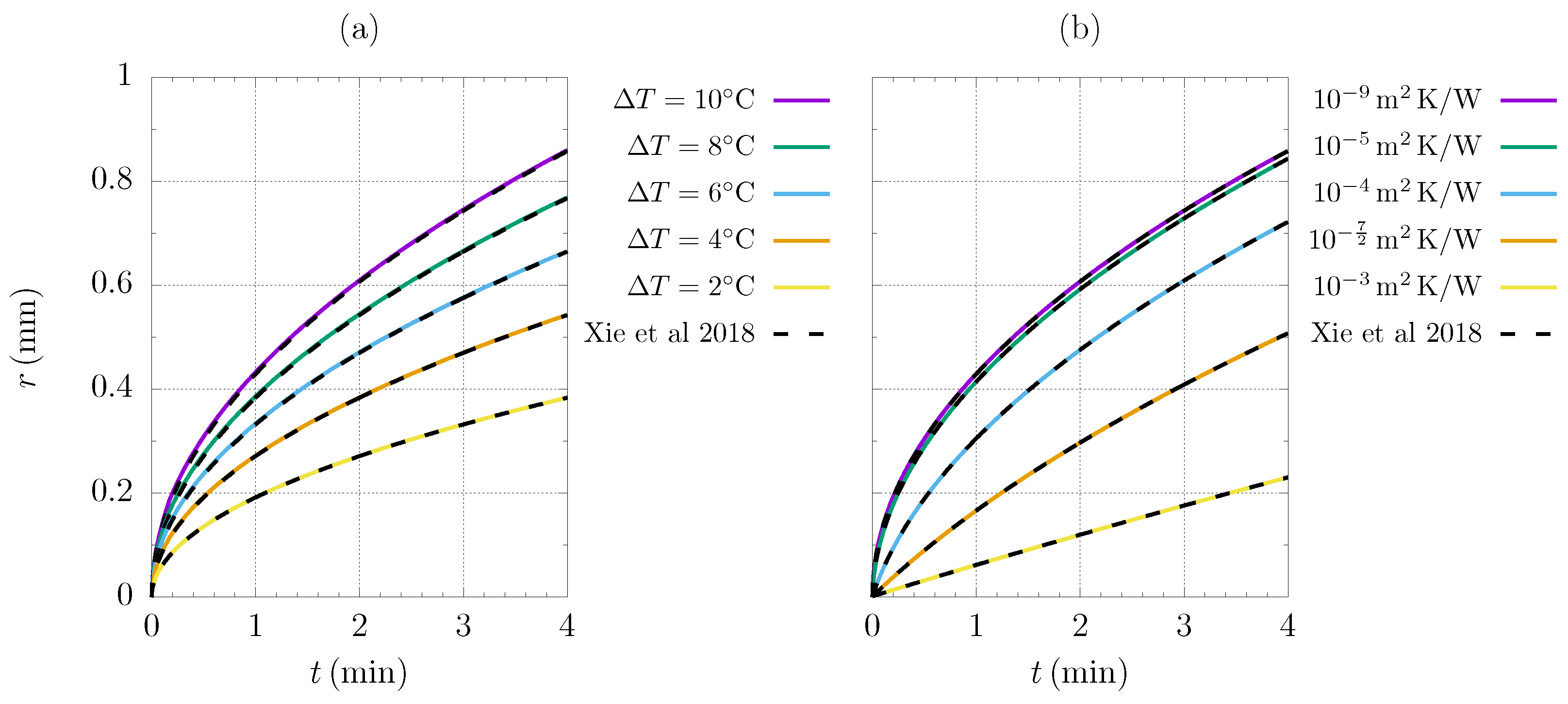
In fact, the model of ref. [19] predicts droplet blow up when . Thus, we must impose a realistic value of the effective nucleating radius to get accurate results and perform a proper comparison with our model; see Equation (4). The effective nucleating radius, which is greater than in presence of a hydrophobic coating [15], was derived at different substrate subcooling and coating characteristics via minimization of the availability function , following the procedure proposed by refs. [15,16,19]. The effective nucleating radius of an hydrophobic surface is shown in Figure 1b as a function of the substrate subcooling and of the coating specific thermal resistance, , while the dashed line represents the critical nucleating radius. Note that the coating layer plays a crucial role in the determination of the nucleating radius, which, in turn, affects the actual nucleation density [14,16]. Equation (14), presented by ref. [19], which is an ordinary differential equation modeling the droplet growth, was numerically solved by imposing the initial condition and compared with the proposed analytical model, see Equation (4), in case of water vapor condensation at under different substrate subcooling and coating layer properties. The results shows a great agreement between the literature model [19] and the proposed growth model through the whole range of investigated subcooling; see Figure 2.
2.3. Droplet Coalescence
During condensation, droplets also grow due to coalescence. At each time step, a coalescence check is performed for every droplet belonging to the population, looking for an overlap with neighboring droplets. Since it is assumed that the coalescence is an instantaneous process, all the detected coalescences are implemented within the time step. Assuming spherical droplets on a hydrophobic surface, the critical droplet distance between two droplets leading to overlap condition is equal to [18]:
The coalesced droplet is placed at the center of gravity of the pre-merged droplets and its mass is equal to the sum of the pre-merged droplets mass:
2.4. Hybrid Surface Implementation
The experimental configuration of ref. [2], characterized by vertical hydrophobic–hydrophilic stripes with prescribed width alternating over a vertical plate, was considered. Dropwise condensation takes place on the hydrophobic regions, while the wettable surface portions are characterized by a continuous liquid film. The migration of droplets from hydrophobic regions to hydrophilic regions due to surface tension forces allows for regeneration of the droplets [2,6], while the falling film ensures liquid shedding from the condensing plate through the hydrophilic regions. In order to enhance the heat transfer, the width of the hydrophobic regions must be much lower than the characteristics droplet moving diameter [2].
In presence of an hybrid surface characterized by recursive geometries such as a series of hydrophobic–hydrophilic stripes (as the one of Figure 3), the computational domain is defined by a single frame of hydrophobic region, with proper boundary conditions implemented through the hydrophobic–hydrophilic boundaries. In particular, following experimental evidences [2], when the base surface of a growing droplet reaches the hydrophobic–hydrophilic boundary, the droplet instantaneously migrates to the more wettable region due to surface tension forces and, thus, exits the computational domain. Note that droplet migration is modeled as an instantaneous process as well as coalescence. The effect of droplets eventually moving due to gravity is not considered, as the hydrophobic width is lower than the moving diameter in practical cases.
3. Result
3.1. Droplet Size Distribution
First, the evolution of a population of droplets condensing on a horizontal plate, of non-dimensional size , characterized by equilibrium contact angle equal to , was simulated. The eventual presence of a coating layer was neglected, giving . A computational domain gives nucleating spots and, thus, ensures that we can get statistically relevant results. After a dependency analysis on the integration time step, it was found that does not affect the resulting cumulative size distribution; thus, it was imposed that . Applying the Rose correlation [14],
it derives that the non-dimensional nucleating radius is equal to , which was chosen for the current simulation. Periodic conditions were applied through boundaries and . The cumulative size distribution of large droplets was computed and validated with the empirical cumulative droplet size distribution, obtained via integration of the well known Le Fevre and Rose empirical correlation [17],
where , which has the unit of measure , is the number of droplets per unit surface with a radius ranging in and is the maximum radius of the droplet population. In general, the maximum radius may be the characteristic moving radius [20], in case of gravity and/or shear driven droplet, or it may be derived from geometrical constraints in case of hybrid surfaces [2]. Here, the actual maximum radius of the condensing droplet population was considered. Note that only large droplets, characterized by a radius in the range were considered to estimate , because Equation (16) is valid when coalescence drives the droplet growth process rather than condensation. The computed probability of having large droplets with radius in the range , obtained from , was compared with:
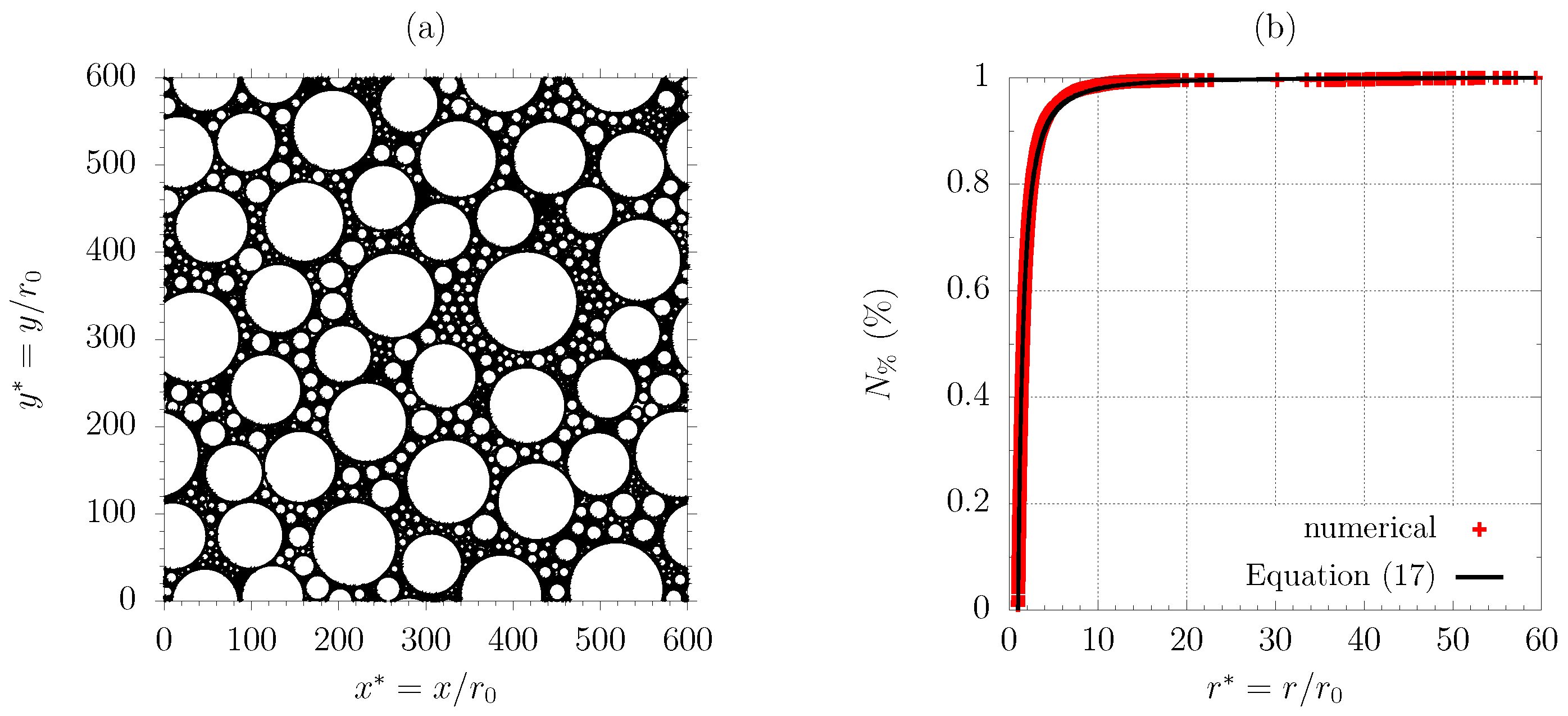
Figure 4a shows the droplet population at on the non-dimensional computational domain of size . The corresponding is compared with Equation (17) in Figure 4b, showing almost a perfect agreement.
The small droplet population, characterized by , in which the growth is driven by a condensation process rather than coalescence, also plays a crucial role in the definition of a simplified, statistically sound model of heat transfer in dropwise condensation [6,20,21]. Due to the tiny size of the small droplets (usually ), poor experimental literature is available, while a correlation, based on the single droplet heat transfer model, was proposed for the small drop size distribution by ref. [1]:
where with unit of measure , , , defined according to ref. [1] and is the critical nucleating radius. Equation (18) can be analytically integrated and recast in non-dimensional fashion, yielding the cumulative size distribution of the small droplets , which is the number of droplets per unit surface with a radius lower than r for :
where the non-dimensional coefficients are equal to:
where and are defined in ref. [1]. Further computations were run in order to verify the numerical cumulative size distribution of small droplets with Equation (19). Again, the coating thermal resistance was neglected, leading to , while two values of the nucleating radius were imposed: , which is consistent with Rose correlation [14]; . A hydrophobic surface with contact angle equal to , of size , was considered. Periodic conditions were applied through the plate boundaries and the integration time step was set to . The numerical cumulative size distribution (including both small and large drops) was computed from the actual droplet population as,
where is the computational domain area and is compared with Equations (16) and (19). Note that, when , the non-dimensional coefficient in Equation (19) reduces to:
meaning that the non-dimensional parameter does not depend on the liquid properties or on the substrate subcooling and contact angle. We further assume that is consistent with the model of ref. [15] in case of negligible coating thermal resistance. As expected, the cumulative size distribution of the large droplet population agrees with the empirical correlation of ref. [17], see Figure 5. The computed, cumulative size distribution of small drops also agrees with the theoretical correlation of ref. [1] in case of , while it is lower than the theoretical size distribution for low droplet radius in case of . However, Equation (18) is not reliable in the limit of small as infinite droplet density is predicted when the droplet radius approaches the critical nucleating radius, .
3.2. Hybrid Surface Characterization
The experimental setup of Peng et al. [2] was replicated. Thus, condensation of water vapor at a saturation temperature of (fluid properties listed in Table 1) over a circular, vertical test section of radius , characterized by alternating hydrophilic–hydrophobic vertical stripes of width and was considered, as shown in Figure 3. In particular, condensation over a stripe of hydrophobic surface of non-dimensional width (white regions in Figure 3) was simulated: periodic conditions were applied through , while the presence of hydrophilic regions at and was implemented as described in Section 2.4. It was assumed that the solution of a localized piece of hydrophobic strip is representative of the whole hydrophobic surface, in terms of specific heat flux and migrating flow rate per unit length. The computational domain height was set to to ensure statistically relevant results. Peng et al. [2] did not provide specific information about the thickness and the thermal conductivity of the self-assembled monolayers (SAM) deposited on the solid substrate to ensure hydrophobicity. We considered in the numerical simulations: such an assumption is consistent with SAMs, characterized by low thermal resistance, of the order of [22]. Computations were run at different normalized width , while the static contact angle was set to , according to ref. [2]. Once the solution becomes self-similar, the computations were stopped and the non-dimensional heat flux from dropwise condensation (DWC) contribution was estimated from the cumulative condensate volume, which was traced during the whole computation. Furthermore, the volume of liquid migrating through the hydrophobic–hydrophilic boundary due to capillary forces was also traced. As shown in Figure 3, droplets with the base surface touching the hydrophilic stripes instantaneously migrate and merge with the thin film flowing over the hydrophilic side. Snapshots of the droplet population resulting in successive instants from a computation at with time integration step of are shown in Figure 6a–c. The actual condensing flux is shown in Figure 6d, where it can be observed that, after the largest droplet, with a base diameter of about half , migrates to the hydrophilic region, suddenly increases due to nucleation and growth of several droplets over the dry spot left by the migrating droplet. In fact, droplet growth is faster during the very first stage, as , see Equation (7). Thus, a small hydrophobic region ensures an higher sweeping frequency and smaller droplets size, with a benefit in terms of DWC heat flux. On the other hand, reducing the hydrophobic width means that the contribution from FWC, which is about one order of magnitude lower in terms of specific heat flux, becomes more important. The self-similar condition is reached when the sweeping cycles of the largest droplets (characterized by ) are observed and, thus, the computed averaged condensing flux stabilizes.
Each simulation represents a family of physical problems, as explained in Section 2.1. Depending on the considered value of , the coalescence radius is univocally defined according to Equation (5). Then, the imposition of the dimensional width of the hydrophobic strip gives the corresponding , which is the input parameter of the simulation in the non-dimensional space. Figure 7a explains the procedure to extend a computation at imposed to a family of physical test cases, characterized by a different combination of and . Further imposing allows to determine the scaling time , Figure 7b, and, thus, to extend the simulations at any substrate subcooling.
The specific heat flux through the hydrophobic region and the migrating flow rate per unit length were estimated as:
where is the number of newly nucleated droplets, is the number of droplets, is the number of migrating droplets, and is defined in Equation (2). Parametric computations were run at different non-dimensional hydrophobic width, with ranging . Each simulation was run on domain, with the hydrophilic regions placed at and periodic condition imposed at , with to ensure statistically relevant information. The time integration step was set in the range and the simulations were stopped after self-similarity was reached.
In order to compute the filmwise condensation (FWC) contribution, the liquid layer solution is required over the hydrophilic regions (grey stripes in Figure 3). It was assumed that a rivulet of width forms over the hydrophilic regions. Applying lubrication theory, a parabolic rivulet profile can be assumed and the flow rate can be estimated by integrating the parabolic velocity profile through the rivulet section:
where is the maximum rivulet thickness. The liquid flow rate at a distance y from the topmost section of the vertical plate is equal to:
where is the condensate flow rate and is the flow rate per unit length, which migrates from the hydrophobic region to the hydrophilic region due to capillary forces. Following Nusselt theory [23], the condensate flow rate is estimated via the energy balance through the liquid rivulet:
Combining Equations (25)–(27) gives an ordinary differential equation,
which can be analytically solved yielding :
Equation (29) has one positive root . Following the experimental setup of ref. [2], let us consider water properties at saturation temperature of , substrate subcooling , and hydrophilic width . The corresponding rivulet height along the vertical plate is plotted in Figure 8a at a different flow rate per unit length , migrating from the hydrophobic to the hydrophilic region, and compared with the film thickness from Nusselt theory [23]. The heat flux along the vertical coordinate is also plotted in Figure 8b, showing that the standard Nusselt theory [23] would lead to inaccurate results. The heat flux through a vertical, hydrophilic strip can be simply estimated as , with being the condensate flow rate at the outlet section. As the condensing surface of [2] is a circular plate of radius R, characterized by vertical hydrophilic-hydrophobic stripes, the specific heat flux through the whole hydrophilic surface was evaluated as:
with being the number of hydrophilic stripes and being the kth stripe height.
Results from DWC computations were combined with the FWC heat flux, which estimation needs , derived from postprocessing of DWC data. The global specific heat flux was estimated as:
First of all, we had to characterize the hydrophobic surface. The actual nucleation density is not given in ref. [2]. However, the present numerical model allows us to estimate it for any experimental point. To do so, we considered an experimental data point, which gives the experimental heat flux at a given width of the hydrophobic and of the hydrophilic stripes and at a given substrate subcooling, and we followed the procedure:
- A number of non-dimensional simulations at different were carried out, with ;
- Each of these non-dimensional computations at different may be representative of the experimental hydrophobic width , if is determined via Figure 7a;
- There will be a single value of , which allows the matching between experimental and numerical heat fluxes. This single value is assumed as the actual nucleation density.
The experimental heat fluxes at fixed hybrid surface geometry, given by , , and different subcoolings were used to trace . It was found that the nucleation density is nearly independent on the substrate subcooling in the investigated range of and the value , corresponding to , allows to accurately reproduce experimental data at , and , as shown in Figure 9a.
The estimated nucleation density was then used in the optimization of the hybrid surface geometry, in order to validate the model with the experimental data of ref. [2] at different hybrid surface geometries, not yet used for characterization of and therefore representing different test cases to investigate. In particular, the effect of increasing the hydrophobic width at fixed was investigated. Numerical data at different values of were used to trace the DWC heat flux as a function of the hydrophobic width and substrate subcooling. To do so, further computations at were run and the available heat flux data were interpolated. The resulting specific heat flux of the hybrid surface is shown as a function of in Figure 9b, at different substrate subcoolings. A maximum of is always observed at . The experimental optimum observed by Peng et al. [2] is also identified with markers in Figure 9b, showing a good agreement with numerical data. Furthermore, the predicted heat flux falls inside the uncertainty range of experimental data for .
4. Conclusions
Steam condensation over an hybrid hydrophobic–hydrophilic surface was numerically investigated via a Lagrangian approach, using an in-house code previously developed and adapted to the modelization of hybrid surfaces. The validation of the details of such a numerical model is not trivial, since it is difficult to experimentally evaluate some of its inputs and outputs. Here, the accuracy of the cumulative size distribution of the larger droplets was successfully validated against the well-established empirical correlation of Le Fevre Rose [17], for the case of an unbounded surface. Experimental data on smaller droplet populations is not available, due to difficult access to the microscopic scale of the nucleation phenomenon, but the comparison with cumulative size distribution of small droplets from the theoretical correlation of ref. [1] confirms the robustness of the implemented numerical model.
Furthermore, the simulation of a practical application demonstrates that the code is capable of producing useful information both in terms of surface characterization and as a design tool for optimizing hybrid hydrophilic-hydrophobic surfaces. In particular, by analyzing the experimental data on condensing heat transfer on a hybrid surface, characterized by alternating hydrophobic–hydrophilic vertical stripes, it was possible to estimate the effective nucleation density of the hydrophobic surface, which is not known a priori in most of the practical cases and is quite difficult to determine experimentally. This type of numerical post-processing of experimental data may thus offer an interesting procedure for the practical characterization of the effective of real surfaces. Once the surface parameters were known, the numerical simulations were able to define the optimal hybrid surface geometries: the good agreement with experiments of ref. [2] allows for a further validation of the numerical model (note that different data from ref. [2] and different geometries were considered for surface characterization and model validation) and demonstrates that numerical computations are an alternative, robust approach to large experimental campaign for hybrid surface design, while simplified, statistically based DWC models are not able to accurately reproduce hybrid surface behavior.
Computations were run on a 8 core, shared memory machine, with the one at the highest requiring around 96 h. However, the generalization of the DWC problem via the non-dimensional approach allowed us to investigate different values of nucleation density , hydrophobic width , and subcooling by changing only a non-dimensional model parameter, . Thus, the computational cost of simulations was reduced by about a cubic root compared to a standard modelization of the DWC problem.
A deeper investigation of size distribution of the small droplet population, which is essential to build accurate and simplified, statistical based models [1,16], could further enhance the accuracy of the procedure, as both experimental and theoretical methods showed some limitations when the droplet size approached the nucleating radius. Further developments within the Lagrangian approach could include the modelization of mechanisms such as coalescence-induced jumping, which is promoted by superhydrophobic surfaces, and droplet movement driven by the wettability gradient. Both of them cannot be simply predicted by the definition of a critical departure radius. Thus, the Le Fevre and Rose correlation [17] may not be able to predict the large drop size distribution accurately [10] and computations may help to access useful statistical information.
Author Contributions
Conceptualization, G.C.; Methodology, N.S.; Software, N.S.; Formal analysis, G.C.; Investigation, G.C.; Writing—original draft, N.S.; Writing—review & editing, G.C. All authors have read and agreed to the published version of the manuscript.
Funding
This research received no external funding.
Data Availability Statement
The data presented in this study are available on request from the corresponding author.
Conflicts of Interest
The authors declare no conflict of interest.
References
- Kim, S.; Kim, K.J. Dropwise Condensation Modeling Suitable for Superhydrophobic Surfaces. ASME J. Heat Transf. 2011, 133, 081502. [Google Scholar] [CrossRef]
- Peng, B.; Ma, X.; Lan, Z.; Xu, W.; Wen, R. Experimental investigation on steam condensation heat transfer enhancement with vertically patterned hydrophobic-hydrophilic hybrid surfaces. Int. J. Heat Mass Transf. 2015, 83, 27–38. [Google Scholar] [CrossRef]
- Miljkovic, N.; Enright, R.; Nam, Y.; Lopez, K.; Dou, N.; Sack, J.; Wang, E.N. Jumping-droplet-enhanced condensation on scalable superhydrophobic nanostructured surfaces. Nano Lett. 2012, 13, 179–187. [Google Scholar] [CrossRef] [PubMed]
- Alwazzan, M.; Egab, K.; Peng, B.; Khan, J.; Li, C. Condensation on hybrid-patterned copper tubes (I): Characterization of condensation heat transfer. Int. J. Heat Mass Transf. 2017, 112, 991–1004. [Google Scholar] [CrossRef]
- Alwazzan, M.; Egab, K.; Peng, B.; Khan, J.; Li, C. Condensation on hybrid-patterned copper tubes (II): Visualization study of droplet dynamics. Int. J. Heat Mass Transf. 2017, 112, 950–958. [Google Scholar] [CrossRef]
- Peng, B.; Ma, X.; Lan, Z.; Xu, W.; Wen, R. Analysis of condensation heat transfer enhancement with dropwise-filmwise hybrid surface: Droplet sizes effect. Int. J. Heat Mass Transf. 2014, 77, 785–794. [Google Scholar] [CrossRef]
- Croce, G.; D’Agaro, P.; Suzzi, N. Optimization of hybrid hydrophilic-hydrophobic surfaces for dropwise condensation enhancement. In Proceedings of the ASME 2019 17th International Conference on Nanochannels, Microchannels, and Minichannels, St. John’s, NL, Canada, 23–26 June 2019. [Google Scholar]
- Suzzi, N.; Croce, G. Numerical prediction of dropwise condensation performances on hybrid hydrophobic-hydrophilic surfaces. J. Phys. Conf. Ser. 2020, 1599, 012006. [Google Scholar]
- Yang, K.S.; Lin, K.H.; Tu, C.W.; He, Y.Z.; Wang, C.C. Experimental investigation of moist air condensation on hydrophilic, hydrophobic, superhydrophilic, and hybrid hydrophobic-hydrophilic surfaces. Int. J. Heat Mass Transf. 2017, 115, 1032–1041. [Google Scholar] [CrossRef]
- Stevens, K.A.; Crockett, J.; Maynes, D.; Iverson, B.D. Simulation of Drop-Size Distribution During Dropwise and Jumping Drop Condensation on a Vertical Surface: Implications for Heat Transfer Modeling. Langmuir 2019, 35, 12858–12875. [Google Scholar] [CrossRef] [PubMed]
- Zhang, B.J.; Kuok, C.; Kim, K.J.; Hwang, T.; Yoon, H. Dropwise steam condensation on various hydrophobic surfaces: Polyphenylene sulfide (PPS), polytetrafluoroethylene (PTFE), and self-assembled micro/nano silver (SAMS). Int. J. Heat Mass Transf. 2015, 89, 353–358. [Google Scholar] [CrossRef]
- Parin, R.; Martucci, A.; Sturaro, M.; Bortolin, S.; Bersani, M.; Carraro, F.; Del Col, D. Nano-structured aluminum surfaces for dropwise condensation. Surf. Coat. Technol. 2018, 348, 1–12. [Google Scholar] [CrossRef]
- Torresin, D.; Tiwari, M.K.; Del Col, D.; Poulikakos, D. Flow Condensation on Copper-Based Nanotextured Superhydrophobic Surfaces. Langmuir 2013, 29, 840–848. [Google Scholar] [CrossRef] [PubMed]
- Rose, J.W. Further aspects of dropwise condensation theory. Int. J. Heat Nad Mass Transf. 1976, 19, 1363–1370. [Google Scholar] [CrossRef]
- Liu, X.; Cheng, P. Dropwise condensation theory revisited: Part I. Droplet nucleation radius. Int. J. Heat Mass Transf. 2015, 83, 833–841. [Google Scholar] [CrossRef]
- Liu, X.; Cheng, P. Dropwise condensation theory revisited Part II. Droplet nucleation density and condensation heat flux. Int. J. Heat Mass Transf. 2015, 83, 842–849. [Google Scholar] [CrossRef]
- Le Fevre, E.J.; Rose, J.W. A Theory of Heat Transfer by Dropwise Condensation. In Proceedings of the 3rd International Heat Transfer Conference, Chicago, IL, USA, 7–12 August 1966. [Google Scholar]
- Suzzi, N.; Croce, G. Numerical simulation of dropwise condensation over hydrophobic surfaces using vapor-diffusion model. Appl. Therm. Eng. 2022, 214, 118806. [Google Scholar] [CrossRef]
- Xie, J.; Xu, J.; Shang, W.; Zhang, K. Dropwise condensation on superhydrophobic nanostructure surface, part II: Mathematical model. Int. J. Heat Mass Transf. 2018, 127, 1170–1187. [Google Scholar] [CrossRef]
- Mirafiori, M.; Abbatecola, A.; Tancon, M.; Bortolin, S.; Del Col, D. A New Model to Study the Life of Millions of Drops During Condensation of Steam. In Proceedings of the 40th UIT International Conference, Assisi, Italy, 26–28 June 2023. [Google Scholar]
- Miljkovic, N.; Enright, R.; Wang, E.N. Modeling and Optimization of Superhydrophobic Condensation. ASME J. Heat Mass Transf. 2013, 135, 111004. [Google Scholar] [CrossRef]
- Song, L.; Zhang, Y.; Yang, W.; Tan, J.; Cheng, L. Molecular Structure Effect of a Self-Assembled Monolayer on Thermal Resistance across an Interface. Polymers 2021, 13, 3732. [Google Scholar] [CrossRef] [PubMed]
- Nusselt, W. Die Oberflächenkondensation des Wasserdampfes. Z. Ver. Dtsch. Ingenieure 1916, 60, 541–546, 569–575. [Google Scholar]
Figure 1.
Non-dimensional droplet growth model, Equation (7), at different values of the coating parameter and fixed (a). Nucleating radius as a function of subcooling and coating thermal resistance ; , water properties evaluated at (b). The dotted line represents the critical nucleating radius, Equation (11).
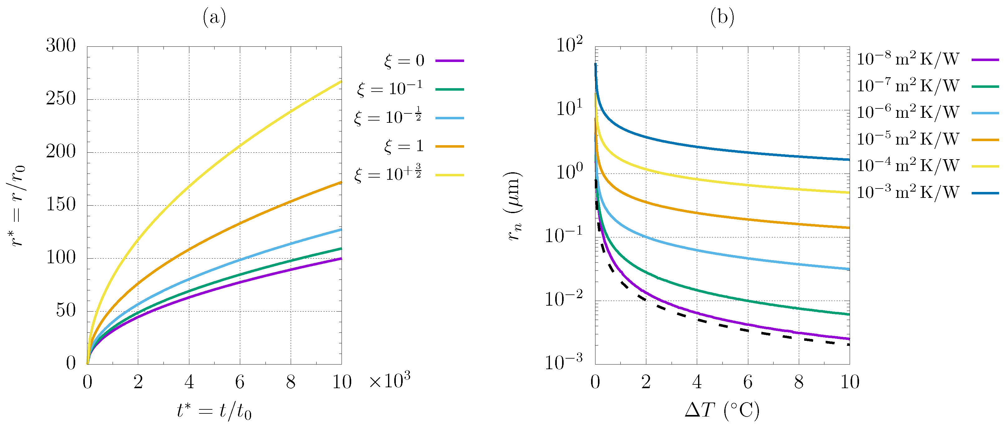
Figure 2.
Droplet radius versus time at different substrate subcooling , fixed (a), at different coating thermal resistances , fixed (b). , water properties evaluated at . The continuous lines represent Equation (4) and the dotted lines are obtained via numerical integration of the droplet growth model by ref. [19].

Figure 3.
Hybrid surface geometry of ref. [2] and droplet migration (here modeled as an instantaneous process) from a hydrophobic region () to hydrophilic () region. The red patterned rectangle denotes the computational domain, where DWC is simulated via Lagrangian model: a periodic condition is applied to both the top and bottom section while a hybrid surface condition is implemented through the lateral boundaries.
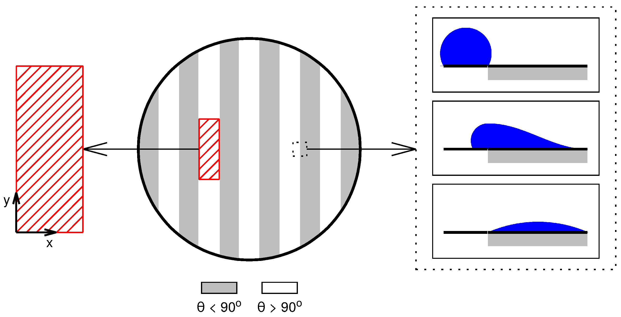
Figure 4.
Droplet population at (a); comparison between corresponding cumulative droplet size distribution, numerically computed, and empirical correlation, Equation (17) (b). , , .
Figure 4.
Droplet population at (a); comparison between corresponding cumulative droplet size distribution, numerically computed, and empirical correlation, Equation (17) (b). , , .

Figure 5.
Numerical droplet cumulative size distribution versus empirical correlations for large droplets, Equation (16), and small droplets, Equation (19): (a), (b). , , , computational domain.
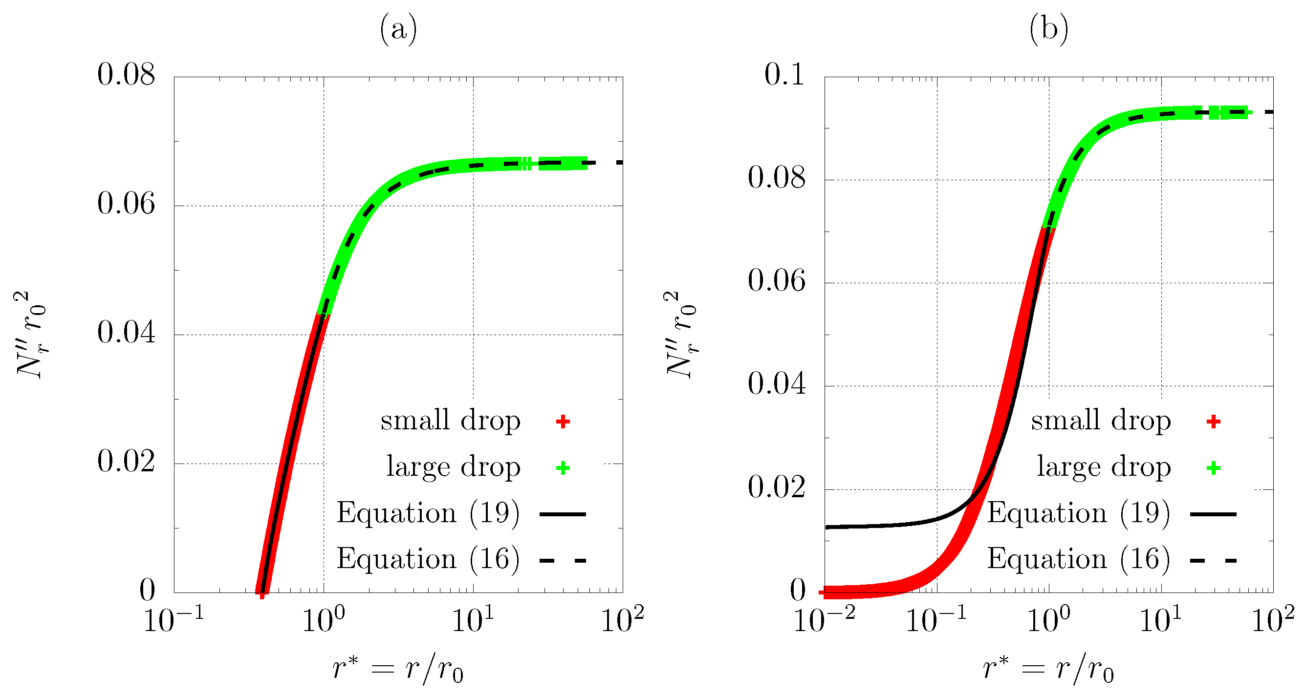
Figure 6.
Droplet population at: (a); (b); (c). Non-dimensional condensing flux, with colored markers corresponding to (d). , , , , .
Figure 6.
Droplet population at: (a); (b); (c). Non-dimensional condensing flux, with colored markers corresponding to (d). , , , , .

Figure 7.
Generalization of results at fixed non-dimensional width to different values of nucleation density and hydrophobic width, each line corresponding to a computation in the non-dimensional space (a). Scaling time, Equation (5), as a function of subcooling and nucleation density, water properties evaluated at saturation temperature (b).
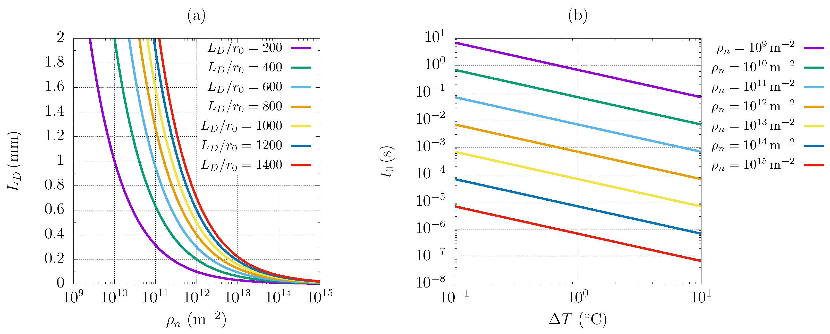
Figure 8.
Maximum rivulet thickness along the plate at different (a); local specific heat flux at different (b). Water properties evaluated at , subcooling , .
Figure 8.
Maximum rivulet thickness along the plate at different (a); local specific heat flux at different (b). Water properties evaluated at , subcooling , .
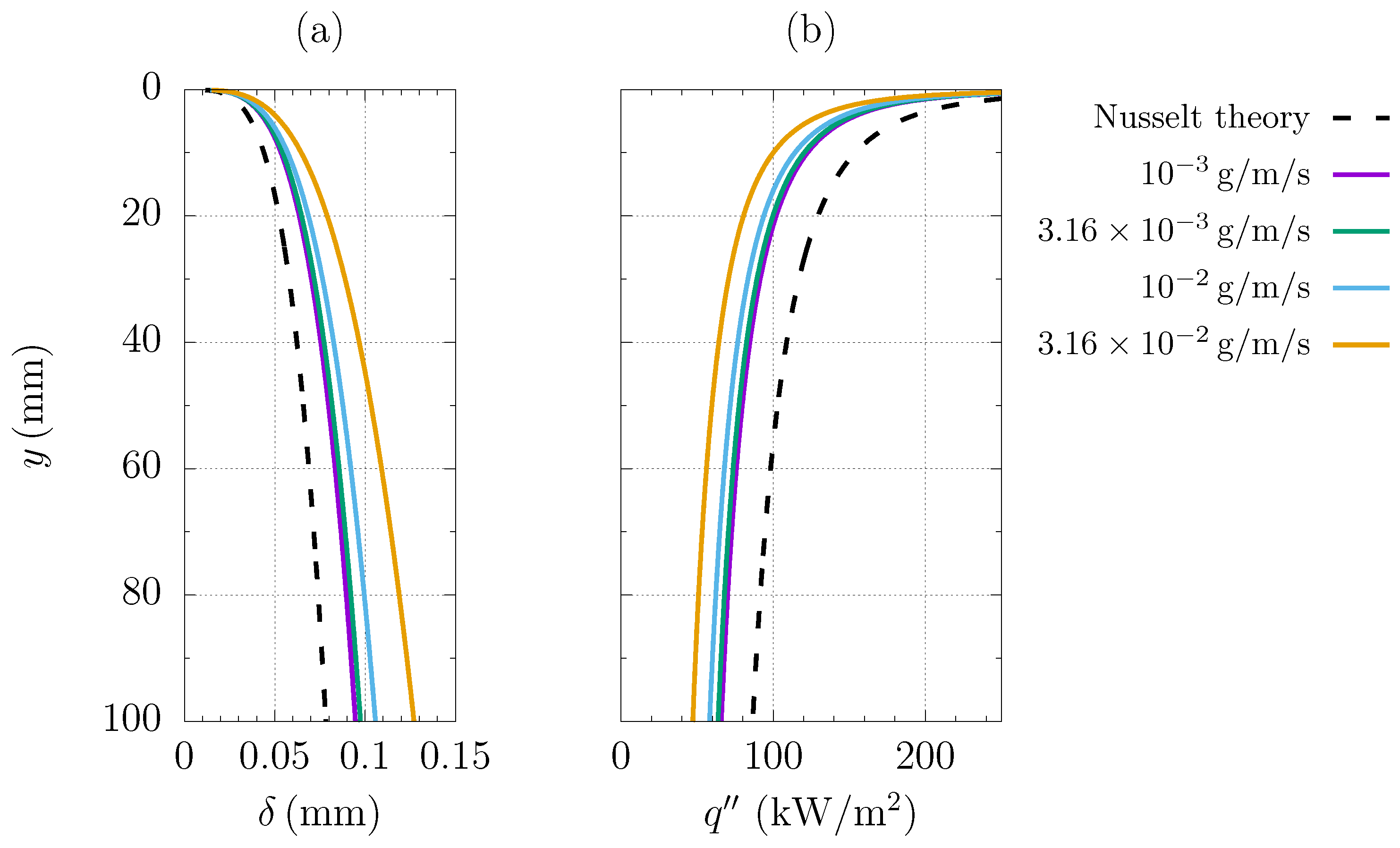
Figure 9.
Predicted vs. experimental [2] heat flux through the hybrid surface as a function of substrate subcooling, , (a). Specific heat flux through the hybrid surface as a function of hydrophobic length , at fixed at (b). Markers with the error bar refer to experimental optimized configuration of [2]. Imposed nucleation density equal to .


Table 1.
Water properties at saturation temperature of .
| 2256 |
Disclaimer/Publisher’s Note: The statements, opinions and data contained in all publications are solely those of the individual author(s) and contributor(s) and not of MDPI and/or the editor(s). MDPI and/or the editor(s) disclaim responsibility for any injury to people or property resulting from any ideas, methods, instructions or products referred to in the content. |
© 2023 by the authors. Licensee MDPI, Basel, Switzerland. This article is an open access article distributed under the terms and conditions of the Creative Commons Attribution (CC BY) license (https://creativecommons.org/licenses/by/4.0/).
Share and Cite
MDPI and ACS Style
Croce, G.; Suzzi, N. Numerical Simulation of Dropwise Condensation of Steam over Hybrid Surfaces via New Non-Dimensional Heat Transfer Model. Fluids 2023, 8, 300. https://doi.org/10.3390/fluids8110300
AMA Style
Croce G, Suzzi N. Numerical Simulation of Dropwise Condensation of Steam over Hybrid Surfaces via New Non-Dimensional Heat Transfer Model. Fluids. 2023; 8(11):300. https://doi.org/10.3390/fluids8110300
Chicago/Turabian StyleCroce, Giulio, and Nicola Suzzi. 2023. "Numerical Simulation of Dropwise Condensation of Steam over Hybrid Surfaces via New Non-Dimensional Heat Transfer Model" Fluids 8, no. 11: 300. https://doi.org/10.3390/fluids8110300