

Dynamics of a Water Droplet Impacting an Ultrathin Layer of Oil Suspended on a Pool of Water

Department of Mechanical, Industrial, and Manufacturing Engineering, The University of Toledo, Toledo, OH 43606, USA
*
Author to whom correspondence should be addressed.
Fluids 2024, 9(4), 82; https://doi.org/10.3390/fluids9040082
Submission received: 6 February 2024
/
Revised: 8 March 2024
/
Accepted: 18 March 2024
/
Published: 25 March 2024
(This article belongs to the Special Issue Contact Line Dynamics and Droplet Spreading)
Abstract
:This study investigates water droplets impacting a two-layered pool, consisting of a deep pool of water above which an ultrathin a suspended layer of silicone oil is present. Initially, the difference between the impact dynamics of water droplets on ultrathin and thick layers of oil were studied. It was found that the existence of an ultrathin layer of oil changes the impact characteristics such how aggressively the jet rises, how the dimensions of the impact impression change, and how the jets are broken down on their tops. Then, in a series of experiments on ultrathin layers of oil, the droplet size, the velocity of the droplets upon impact, and the viscosity of the oil layers were changed to observe and measure the characteristic dimensions of the formed craters and the jets. It was observed that when the viscosity of oil layers decreased to a minimum of 1 (cSt), the jet height and crater sizes increased to their maximum value. In addition to the effect of the oil viscosity, it was found that the droplet size and the release heights of the droplets were in the next orders of significance in determining the impact dynamics. The impacts were also characterized qualitatively by specifically looking into the crown and crater formations, pinch-off modes in jets, and number of formed secondary droplets. As well as the quantitative conclusion, it was found that the major affecting parameter in changing each of these qualities was the viscosity of the suspended oil layer.
1. Introduction
Droplet impact on surfaces can be seen in a wide range from daily life to industrial applications such as inkjet printers, pesticide sprayers, irrigation systems, fuel injection in engines, fire extinguishers, metal quenching systems, and plasma spraying, among others [1,2,3,4,5]. The surfaces that experience impacting droplets could be a solid, a pool of liquid, or a thin liquid film laid either on a solid substrate or suspended on a pool of another immiscible liquid [6,7,8]. Properties of the impacting droplets (e.g., size, velocity, viscosity, surface tension, etc.) and characteristics of the pool/thin film liquids (e.g., thickness, viscosity, surface tension, etc.) and/or solid surfaces (e.g., surface energy, roughness, polarity, wetness) all influence the outcome of the impact [9,10]. For instance, modulating roughness and energy of solid surfaces has resulted in bouncing/repelling of the impacting droplets and development of so-called superhydrophobic surfaces [11,12,13]. Other potential outcomes of such impacts include homogenous wetting, splashing, and impalement/sticking [14,15]. On the other hand, droplets impacting miscible or immiscible liquids (ultrathin film or pool) might lead to outcomes such as crater and jet formation depends on liquid thickness, temperature, viscosity, surface tension, etc. [16]. Effects of droplet size, the number of falling droplets, the impact velocity, and condition of the impacted pool of liquid (temperature, viscosity, stationary/moving, etc.) have all been investigated [17,18]. These studies have mainly focused on the formation and dimensions of the craters upon impact, the retraction of the craters, and the consequent jet formations [19,20,21].
Inertia, capillary, viscous, and surface tension forces are all involved in studying droplet dynamics. Competing effects of these forces have been studied through various dimensionless numbers such as Reynolds (Re), Weber (We), Froude (Fr), Ohnesorge (Oh), Bond, and capillary [22,23,24]. Among those, the We and the Re numbers have been used mostly to explain various phenomena involved in droplet dynamics. For instance, Manzello et al. defined a critical We for jet break up that was independent of the pool depth [25]. Castillo-Orozco et al. found that the jet height increases as the We number increases and that the chances of the jet break up significantly decreases in higher droplet viscosity [26]. Ding et al. studied dynamics of viscous droplets impacting a less viscous pool of liquid (a mixture of water and glycerol with the oil content changing from 50 to 100 (wt.%), providing various dynamic viscosity values). They observed two successive jet formations after the impact in which the first jet corresponds to climbing behavior of the more viscous droplet and the second one is the so-called Worthington’s jet [27]. Che et al. showed that the miscibility of two interacting liquids (i.e., droplet and pool of liquid) play a major role in determining outcome of the impact. They found that when a water droplet impacts an oil layer a compound jet forms while when an oil droplet impacts a water layer, the droplet spreads quickly [28]. Jain et al., investigated the effect of viscous oil droplets impacting on a pool of water, showing a correlation between the droplet viscosity and the crater depth. They showed that as the viscosities of the droplets and the pool liquid becomes closer, shallower craters are formed [29]. One of the few studies on the impact of droplets on multi/double layered pools was conducted by Kim et al., where oil droplets impact a suspending oil layer on a pool of water. With different droplet diameters and suspended layer thicknesses, they found out that with even a very thin layer of oil, the jet height and the crater depth are smaller when compared to the case in which no suspended oil layer is present [30]. In a similar study by Zhang et al., a water droplet impacted a suspended heptane layer on a deep pool of water. The study concluded that with changing the impact velocity (We number) and the thickness of the suspended oil layer, four types of impact outcomes observed (single crown-jet, single crown-bubble, double crown-bubble, and double crown-jet). They also showed that the existence of the water-oil interface substantially reduces the crater dimensions [31]. There are other works focusing on the impact of droplets on solid surfaces with engineered properties and thin films of liquid spread on solid substrates. For instance, Raiyan et al. used macrotextures to reduce contact time of viscous liquids impacting superamphiphobic surfaces [32]. On the other hand, Yeganehdoust et al. used a three phase flow model to study air entrapment during droplet impact on a thin film of immiscible liquid [33].
More recently droplet impacts on multilayers of immiscible liquids have been studied. Among various parameters, thickness of each layer have shown major effect on the characteristics of the crater and jet formation [31,34]. When a droplet impacts a multilayer of immiscible liquids, relative thickness of the outmost liquid (suspended layer) to the droplet size plays a major role in characteristics of the impact. The physics becomes more complex when this relative thickness becomes ultrathin [30]. Despite previous reports, there are no major efforts that study dynamics of droplets impacting ultrathin layer of a liquid suspended/floating on a pool of another immiscible liquid.
Here, dynamics of water droplets impacting an ultrathin layer of silicone oil suspended on a deep pool of water is investigated. Effect of oil viscosity and droplet size to oil thickness ratio on impact dynamics are studied. Characteristics of crater, crown, jet, and secondary droplets and their dependence to droplet/bilayer liquid (ultrathin silicone oil and pool of water) properties are studied in detail. It is found that an increase in the droplet size leads to an increase in jet height and crater dimensions (i.e., depth and width). In addition, higher We and Re numbers lead to formation of tall crowns and jets with top pinch-off modes, respectively. Furthermore, it is found that the oil viscosity plays a major role in defining the dynamics of the impact. Building upon these insights and drawing from the work of Yongsheng Wu et al. [35] we recognize that environmental factors such as rainfall must be considered in the context of oil spills. Their study underscores that rain-induced turbulence significantly affects oil droplet size and dispersion rates, similar to the turbulence caused by wind-induced waves. This phenomenon is critical for understanding the maximum droplet sizes and dispersion fractions in varying conditions, including the use of chemical dispersants. Their findings suggest that heavy rainfall can influence the dispersion of light and heavy oils to varying degrees, which should be considered when developing strategies to mitigate oil spill. Integrating this knowledge, our study will further elucidate the potential spread of oil spills over oceans due to rain, providing insights for better handling of such environmental crisis.
2. Results and Discussions
Droplet dynamics involves competition of inertia, viscous, surface tension, and gravity forces, among others. To understand significance of each force, various dimensionless numbers are employed. Weber (We) number represents ratio of inertial force to surface tension force and is defined as (effective impact Weber number) while Reynolds (Re) number represents competing effects of the inertial force to viscous resistance and is defined as . Here is the impact velocity, is the droplet density, is the droplet diameter, is the droplet kinematic viscosity, and is the effective surface tension of the pool liquid (ultrathin silicone oil suspended on water or just water). As shown in their mathematical forms, these numbers vary by droplet viscosity, droplet size, impact velocity, equivalent surface tension, and the viscosity of the liquids [36]. Existence of an ultrathin layer of oil suspended on a pool of water changes some of the properties mentioned above. For instance, the active surface tension of the impact changes to interfacial tension since at the same time the water droplet is in interaction with air, and an oil layer suspended on a pool of water [30]. Figure 1C shows three different combinations of pool surface in which the oil thickness (H) varies from 0 to ultrathin layer () to comparable to water droplet diameter (). In the case that there is no oil layer present (), the interfacial tension would be equal to that of air-water surface tension. When the oil layers are added (i.e., from ultrathin to thicknesses close to droplet diameter), the interfacial tension between the water droplet, air, and oil layer would become equal to a combination of oil-air and oil-water surface tensions. Finally, when the oil layer is thick enough (i.e., ), the interfacial tension changes to just the surface tension of oil-water without considering the term for air-water or air-oil surface tensions [37,38]. By adjusting the surface tensions (interfacial tensions in the case of ultrathin oil layer), the effective surface tension () is calculated based on each experimental combination (equations shown in Figure 1C are adopted with modifications from Kim et al. [30]). Knowing the effective surface tension, the effective number is calculated and used for data analysis. Since the only changing parameter in the ultrathin oil layer cases is the equivalent surface tension, the rest of the dimensionless numbers are kept and used as they were. Figure 1 shows the overall experimental setup and steps and Table 1 summarizes the liquid properties used in this study and the ranges of their values [39].
When a water droplet impacts an ultrathin layer of silicone oil suspended on a pool of water, its kinetic energy leads to deformation in the droplet and the pool liquid. Figure 2 shows different stages of the impact dynamics. Upon impact, the liquid pool surface deforms forming a crater with a depth of D and width of W significantly larger than the droplet diameter (d). This phenomenon is also called the crater evolution (step 2). Next, the crater retracts and pushes a column of liquids (water and silicone oil) upward forming a varying-height jet which is known as jet evolution and build up (step 3). In some cases, as the jet height reaches to its peak (based on initial impact conditions), the jet breaks up and forms secondary/child droplets (step 4). This moment is exactly when the jet peaks in its height and starts to descent. Generally, this region is called pinch-off or jet break-up and it is where the secondary/child droplets form from the descending liquid column (step 5). In some instances, as the jet descends the weight of that liquid column forms another crater upon impact to the pool forming a secondary crater (step 6). This might lead to formation of a secondary jet which is not typically tall and ultimately results in a liquid dimple and a tertiary droplet (step 7). However, from the point that the jet is descending, the process of droplet impact moves toward a stable state. At this stage, the droplet initially gets trapped in the suspended oil layer and eventually it passes the oil layer and meets with the deep pool of water, mixing with it (step 8). Movie S1 illustrates all the introduced stages of the impact. The video corresponds to a droplet impact falling from height of Z = 750 (mm) with a diameter of (mm) on an ultrathin layer of silicone oil with kinematic viscosity of (cSt) suspended on a deep pool of water.
2.1. Effect of Oil Layer Thickness
Figure 3A represents three different silicone oil thicknesses employed in this study. The oil thicknesses of and 8 (mm) are considered thick layers (), the oil thickness of (mm) is considered a thin layer (nearly equal to the water droplet diameter or ) and finally, the ultrathin oil layers in which . When the oil is ultrathin () it does not resist the impacting water droplets much. This leads to formation of deep craters regardless of oil viscosity. However, when the suspended oil becomes thicker ( and 8 (mm)) it resists the water droplet upon impact, leading to a decrease in the depth of formed craters. However, the kinetic energy of the impacting droplets leads to creation of wider craters instead. This can be seen when plotting the normalized depth () vs. normalized width of craters () (Figure 3B). It can be hypothesized that an increase in the normalized jet height () means less energy dissipation during the droplet impact. Therefore, it can be concluded that the wider crater formation leads to more energy dissipation than the formation of a deeper one. Difference between water droplets impacting an ultrathin vs. a thick oil layer is evident in characteristics of impact dynamics. With no research on dynamics of a water droplet impacting an ultrathin layer of oil suspended on a pool of water, characteristics of that impact such as formation of crater, crown, jet, and secondary droplets are studied in detail and presented here. Movie S2 compares the characteristics of impacts on ultrathin and thicker layers of suspended oil on a pool of water. The pool surface conditions are with no oil, ultrathin oil layer, and thicker oil layers (H = 3, 5, and 8 (mm) and (cSt)). The droplet size is (mm) released from (mm). A view of the same impact is presented in Movie S3.
Figure 3C shows the difference between ratio of crater dimensions (in terms of ) for impacts on ultrathin layers oil in comparison to similar impacts on thicker oil layers. It can be seen that for impacts on ultrathin layers of suspended silicone oil, the majority of the impacts form a crater with while for impacts on thicker suspended oil layers the crater dimension ratio changes to . Although the impacts on (cSt) and (mm) falls below the margin of thin and thick oil layers, it can be safely anticipated that the impacts on thick oil layers are different in nature.
Finally, Figure 3D shows that despite dissipation of the kinetic energy upon droplet impact, an increase in inertial forces leads to enhanced retainment of the energy leading to a jet formation with increased normalized jet heights ( which will be discussed in next sections). However, this trend is less intensified when the water droplets impacted a thicker layer of oil suspended on a pool of water (). This can be explained due to surface tension mismatch between the water and the silicone oil and the corresponding damping nature. As expected, when the oil is ultrathin, a linear trend between the impact We number and the normalized jet height () is observed. In addition, a decrease in oil viscosity leads to an increase in the normalized jet height, especially where an ultrathin layer of oil is suspended on a deep pool of water. Overall, at a given number a decrease in oil viscosity or its thickness leads to taller jet formation.
2.2. Vertical Displacement of Liquid and Formation of Crowns
As the falling water droplets impact the pool surface (water only or ultrathin oil on water), a deformation occurs in both the falling droplets and the pool surface [40,41]. The impact leads to liquid deformation and consequently to formation of craters. However, the liquid retracts due to surface tension forces resulting in its vertical displacement [42,43]. The extent of vertical displacement in the liquid depends on the impact condition such as We number. In addition, the effect of pool surface viscosity should always be considered as surface/interfacial tension and viscosity forces are in constant interaction during liquid deformation and motion. Four different impact conditions and the extent of vertical pool liquid displacement, up to formation of a full crown, are shown in Figure 4A–D. As the impact conditions change, it can be seen that the viscosity is playing an important role.
When the effective Weber number is small (), in most impact instances, no vertical displacement occurs regardless of existence and/or viscosity of the suspended ultrathin oil (see Figure 4E). With an increase in the effective Weber number (), slight/short vertical displacement in the liquid is observed during the crater formation. This is expected given the increase in the kinetic energy of the impacting droplets. Further increase in the Weber number () leads to medium and large vertical displacements in the liquid. However, at higher Weber numbers adding an ultrathin layer of silicone oil on pool of water leads to an overall decrease in the extent of vertical displacement. This can be due to the surface tension mismatch and immiscibility difference between the silicone oil and the water. In addition, the viscosity of the silicone oil can also play a role. At higher Weber numbers (), an increase in the viscosity of the ultrathin silicone oil from 1 to 100 (cSt) leads to an overall decrease in the extent of vertical displacement in the liquid and consequently crown formation. It is hypothesized that more viscous oil leads to enhanced energy dissipation during the impact and less likelihood of large vertical displacements at high Weber numbers. When the vertical displacement of the liquid is large it leads to so-called crown formation which is visible at the tips of the displaced liquid (Figure 4E). It has been shown that the crown becomes more enhanced when the water droplet impacts the pool of water without any suspended ultrathin layer of oil [44].
Figure 4F shows the behavior of the impact regarding its and numbers. As these dimensionless numbers increase, there is a higher chance in observing a full crown formation. Based on the impact Re numbers, three distinct regions of no displacement, short displacements, and full crown formations could be observed over the ranges of , 11,000, and 11,000 15,500, respectively. However, the instances of medium deformations were available over a wide range of impact numbers ( 15,500) which was expected as these deformations were transition modes between a short deformation and a full crown formation. Although it is possible to distribute this category to short displacements and full crowns, they are kept in order to have the highest distinction between all the observed categories. The and numbers include the terms for impact velocity and the droplet size themselves. Thus, it can be concluded that as the release heights and droplet sizes increase, a linear increasing trend will be observed for chances of having full crown formations.
2.3. Crater Formation and Its Characteristics
Upon droplet impact on a pool of liquid (ultrathin silicone oil suspended on water), deformations occur both in the droplet and the liquid pool leading to formation of craters with various depths and widths 44. As discussed earlier, the craters are wider than deeper () due to more resistance droplets experience in the impact direction (see Figure 3B,C). However, as the number increases, the difference between the width and depth of the craters fades away. This means that at impacts of larger droplets from higher release heights, the craters are formed closer to a hemisphere shape rather than oval-shaped ones which occurs during impact of smaller droplets released from lower heights. It can be also seen that larger craters form when the impacts are more aggressive (increase rate of D is higher than that of W). Thus, such impacts result in increased depth of craters rather than width which enhances the retraction and formation of full crowns. This trend is mostly seen where there are comparable values of W and D () (see Figure 5B). Furthermore, an increase in droplet size and its release height collectively leads to an increase in impact number. As expected, the enhancement in the kinetic energy leads to larger crater formation as evident by an increase in the overall dimension () of the formed craters. This consequently leads to enhancement in the vertical displacement of the liquid, resulting in increased occurrence of full crown formation. Figure 5C,D represent the effect of droplet size and release height on enhanced chances of full crown formations. For larger droplets released from a higher height (larger impact ), most of the impact instances results in a full crown formation. A real snapshot of the impact instances with droplet sizes 1–4 are shown in Figure 5A where in similar impact conditions, increasing the droplet size causes an increase in the crater dimensions and consequently formation of taller jets which will be discussed in the following sections.
2.4. Jet Pinch-Off Modes
Consequent to crater formation and its retraction, the excessive energy of the impacting droplets leads to vertical displacement of the liquid forming a jet [45]. Depending on the extent of energy dissipation during the impact, liquid jets with different heights form some of which experience a disintegration and a pinch-off on top of the liquid pillar. This occurs due to different velocities in a pillar of the liquid that moves upward [46,47]. The process starts with elongation of a column of liquid followed by necking and partial separation, as shown in Figure 6A. If observed pinch-off modes are categorized as low, medium, and top depending on their height as shown in Figure 6B. Figure 6C shows that with an increase in the impact number an increase in the normalized jet height () is observed. As shown in Figure 5D, with increased release heights, the crater size increases which translates to more severe crater retraction since more liquid is displaced. As the retraction became more aggressive, a higher normalized jet height was occurred, consequently leading to enhancement in top pinch-off modes. However, at any given release height, there were several instances of top pinch-off which means the release height alone is not a well-defined indicative of the pinch-off modes.
On the other hand, the size of the droplets is considered as the other impacting parameter in changing the impact number. As shown in Figure 6D, with increased droplet sizes, a higher number of top pinch-off instances were observed. Similar to the droplets released from a higher height, when the larger droplets impact the pool surface, higher kinetic energy is converted and larger craters form. Depending on the properties of the droplet and pool liquid properties (such as viscosity), they will deform to different extents. For instance, if the pool surface has a higher equivalent viscosity, the impacting droplets deform more easily. In general, the impacts made wider craters rather than deeper ones which can be obviously seen in Figure 5C,D but with an increased droplet size and release height, this difference became smaller (higher impact numbers in Figure 5B). Overall, increase in effective number leads to formation of craters with larger depth and width. This leads to enhanced vertical displacement of the liquid, ultimately forming crown. Upon crater retraction the height of the formed jets depends on the size of craters and extent of vertical displacement in the liquid. Observed increase in the depth and width of the formed craters ultimately lead to taller jet formations that experience top pin-off modes.
Figure 6E shows that as the viscosity of the ultrathin oil layer increases the dissipation of kinetic energy increases during the impact. This leads to formation of smaller craters and consequently shorter jets that result in low or no pinch-offs. For instance, an impact on = 100 (cSt) silicone oil is less severe compared to the same impact on a lower viscosity (e.g., = 1 (cSt)) as in the former, the resisting viscous forces of the pool surface are larger. On the other hand, surface tension plays a key role when comparing the impacts on silicone oil of = 1 (cSt) and pool of water with the same viscosity. Since the oil layers are ultrathin (), the effective surface tension () is roughly equal to the sum of oil-air ()) and oil-water () surface tensions and greater than the water-air surface tension ()) [30]. Upon impact, both water surface and oil layer deform. However, on the oil layer, the crater faces a resistance caused by higher surface tension and retracts more aggressively. As a result, the formed jets are taller for the instances of impacts on = 1 (cSt) oil layer and the chances of observing top pinch-offs increase [29].
Based on the presented data, it can be concluded that for larger droplets and higher release heights impacting less viscous ultrathin oil layers, it is highly expected to observe deeper craters, taller jets, and higher chances of top pinch-off (see discussion on Figure 6E). Figure 7A shows that the minimum ratio occurs at impacts on = 1 (cSt) oil layer and the highest number of instances with top pinch-off occurs at this condition. As a result, it can be concluded that with a deeper (or less wide) crater, the chances of experiencing a top pinch-off increases. Since the instances of top pinch-off occur nearly in any given impact conditions (a combination of release height and droplet size in Figure 7B), it is apparent that the major affecting parameter in defining the pinch-off modes is the viscosity of the target surface followed by its surface/interfacial tension. Nearly all the impacts on the low viscosity oil layer resulted in top pinch-off modes, justifying this finding. Although the droplet size and the release height are the other important contributing factors to categorize the pinch-off modes (Figure 6C,D), the major effect is reflected by the pool surface conditions. Figure 7C represents impacts on different pool surfaces from different heights, corresponding to the presented discussion. When water droplets impact a pool of water only instead of oil, the formed craters disappear faster due to lower viscosity of water when compared to oil. This results in less energy dissipation during the impact and formation of taller jets with potential occurrence of a pinch-off. Adding an oil with a high viscosity to the pool of water results in formation of craters with increased width to depth ration () due to high shear forces leading to shorter jet formation that do not experience top pinch-offs. However, for the impacts on a pool of water and = 1 (cSt), the ruling factor seems to be interfacial tension of oil-water-air. It is hypothesized that the suspended oil layer acts as a cushion but due to its negligible thickness it does not provide any significant resistance to deformation and further facilitates the impingement of the falling droplet. Although a deeper crater formation is expected for impacts on a pool of water, an opposite trend was observed. This is a distinct observation when compared to the studies on conventionally thicker oil layers [29,48].
2.5. Secondary Droplet Formation
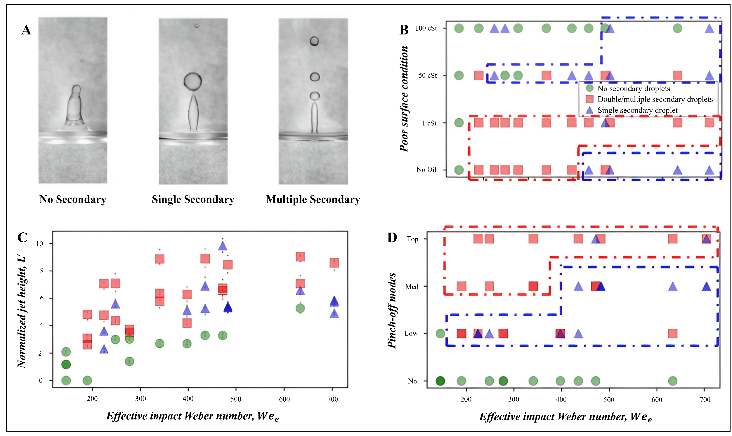
When jet pinch-off occurs, the liquid body (jet) divides into a main descending column and a secondary droplet. Different pinch-off modes (low, medium, and top) result in different types of secondary droplet formations [49]. A single droplet or a series of droplets (two or more) might form during jet pin-offs depending on the impact condition [50,51,52]. Here, the results are categorized into three distinct groups of: no secondary droplets, single secondary droplet, and double/multiple secondary droplets as shown in Figure 8A.
When a water droplet with a threshold effective Weber number () impacts a pool of water, the resulting jet always experiences a pinch-off with one or more secondary droplets formation. This is valid even after adding an ultrathin layer of silicone oil with kinematic viscosities of = 1 and 50 (cSt) to the pool of water. However, when the silicone oil viscosity increases further to = 100 (cSt) the formed jet does not necessarily experience a pinch-off, thus no formation of secondary droplets. With a = 100 (cSt) silicone oil suspended on pool of water, at higher numbers a single secondary droplet form in rare occasions of impacts. However, adding a less viscous ( = 1 or 50 (cSt)) ultrathin layer of oil to the pool of water leads to enhanced chances of jet pinch-offs, forming single or multiple secondary droplets (see Figure 8B). Comparing impacts on a deep pool of water and a suspended oil layer of = 1 (cSt), at higher impact numbers (), the impacts on pool of water mostly resulted in single secondary droplet formation while for lower numbers a greater number of secondary droplets were formed. Since the overall air-water surface tension is less than the sum of interfacial tensions between oil and air and oil and water, the retraction of the crater formed upon impact on the pool of water was less abrupt compared to that of 1 (cSt) oil layer (see discussion on Figure 6E). In addition, higher impact numbers result in a thick compound jet where a higher volume of liquid is displaced compared to singular jets (lower numbers). As a result, the necking is less likely to happen for cases of compound jets and lower chances of pinch-off and formation of multiple secondary droplets will exist (see Movie S4).
Figure 8C shows that over a wide range of numbers and normalized jet heights different numbers of secondary droplets form. Once a threshold number is reached, double/multiple secondary droplets are observed during pinch-off of even short jets. This shows that the secondary droplet formation is not exactly following the increasing trend observed for the crown formation as a function of the impact numbers. However, there is a threshold for the normalized jet height () that is needed to lead to formation of single/double/multiple secondary droplets. Overall, a combined condition of increase in effective Weber number and normalized jet height lead to formation of single/double/multiple secondary droplets during jet pin-offs.
Figure 8D presents the data for secondary droplet formations based on pinch-off modes. At different pinch-off modes (Low, Med, and Top), the instances of multiple secondary droplets increase over any given impact number. Most likely for any instance of top pinch-off and regardless of the impact numbers, there would be multiple secondary droplets formed. For medium (Med) pinch-offs there is a higher chance of multiple secondary droplet formation by critical but for higher values mostly single secondary droplets form. Lower numbers reflect smaller impacting droplets released from a lower height which are more likely to form thin singular jets. This leads to a more feasible necking and pinch-off leading to formation of multiple secondary droplets, compared to thicker compound jets formed at higher impact numbers. It can be concluded that viscosity of the suspended oil layer is the major determining factor in qualitative analysis of secondary droplet formation. Table 2 summarizes how variations in Weber number and oil layer thickness influence the observed jet pinch-off modes and various liquid displacement during crater formation.
While this study has provided valuable insights into droplet dynamics on ultrathin oil layers, we acknowledge certain limitations. Our experiments were conducted under controlled laboratory conditions, which may not fully capture the complexities of natural environments where factors such as wind, temperature fluctuations, and surface heterogeneity can play a role. Furthermore, we focused on a specific range of droplet sizes and velocities limiting the range of studied We number which can be broadened in future studies.. In addition, oil with varying surface tension and thickness can be explored further to better mimic crude oil that spills over oceans/seas.
3. Conclusions
In the current study, it was found that with different impact conditions, different impact dynamics are observed. Initially, it was observed that droplet impacts on ultrathin and thicker suspended silicone oil layers express different impact characteristics; impacts on ultrathin oil layers relatively result in deeper crater formation followed by taller jets. After observing the significant difference in dynamics of impacts on ultrathin oil layers, the experiments were focused on investigating the different characteristics of such impacts. In that regard, it was found that as the impact increases, the chances of formation of full crowns increase as well. Most of the instances of full crown formations occurred in impacts on a pool of water or = 1 (cSt) silicone oil. Addition of more viscous oil layers reduced the chances of full crown formation. Furthermore, the size of the formed craters enhanced with increase in droplet size and release height (higher impact numbers). In addition, at higher impact numbers, the crater dimension ratio () decreased, shifting the morphology of the craters to near-sphere shapes. Jet pinch-off modes were observed to be directly tied to droplet size and release height while the major effect was reflected by the pool surface conditions.
Going forward, it was observed that as the oil viscosity decreases, the chances of observing top pinch-offs increased. Comparing the case of a similar viscosity ( = 1 (cSt) silicone oil and a pool of water), the effective surface tension plays the major role by increasing the depth of the craters and resulting in taller jets and more instances of top pinch-offs for impacts on = 1 (cSt) ultrathin oil layer. Other than that, the impacts on this viscosity oil resulted in formation of deeper craters compared to the similar impacts on a pool of water. This is a key characteristic difference compared to the results of previous studies that focused on thicker oil layers. By different behaviors in pinch-off modes, it was expected to have a notably different number of secondary droplet formations. It was observed that secondary droplets can form over a wide range of impact numbers. However, the highest chance of observing multiple secondary droplets is at lowest oil viscosity of = 1 (cSt), followed by impacts on a pool of water. The number of secondary droplets is directly tied to the dynamics of jet formation and pinch-off modes.
It was observed that for impacts on a pool of water, as the impact numbers increase, the compound jets form (relatively thicker compared to singular jets) which decreases the chances of necking and pinch-off. As a result, lower number of secondary droplets were formed at this specific impact condition. For a similar reason, the impacts resulted in medium pinch-off form multiple secondary droplets at lower impact numbers while most top and low pinch-off instances resulted in multiple and single secondary droplet formation, respectively.
Future studies can consider impact of water salinity to better mimic ocean water. There is also a great need for studying the impacts of different types of crude oils to better understand impact of rain droplets on crude oil spill over oceans. It can also help in drawing generalized inferences for other industrial applications and environmental conditions by extending the range of the number using wider range of droplets sizes and impacting velocities/release heights.
4. Materials and Methods
4.1. Experimental Setup
Figure 1A shows a schematic of the setup used in this study and the corresponding parameters. Experiments are conducted in a controlled environment (i.e., temperature of 21–23 °C, and relative humidity of 75–80%). A large transparent container (100 mm × 100 mm × 110 mm) is made of polycarbonate and filled with deionized water (Millipore Sigma, Burlington, MA, USA). The container is made large enough to minimize any wall effects [26]. Silicone oils with kinematic viscosities of , and 100 (cSt) ( MicroLubrol, Clifton, NJ, USA) and thicknesses of , and 8 (mm) are poured on the deep pool of water. Another set of experiments are conducted in which droplets of the silicone oil (with various viscosities as listed above) are placed on the deep pool of water, forming a suspended ultrathin layer of oil (). Water droplets are generated with a syringe pump (NE-300 Just Infusion, Braintree, MA, USA) at a flowrate of and using four different needle diameters, (, and 2.1 (mm)) to obtain droplets with different diameters (d). Based on the needle sizes, the droplet diameters (d) are mathematically calculated to be around and 4.1 (mm), respectively. These numbers are also verified through acquired images. The water droplets are released from different heights, (Z = 250, 500, and 750 (mm)) to obtain different impact velocities upon reaching the pool liquid. A high-speed camera (Olympus i-speed, Digital Solutions Americas, Bethlehem, PA, USA) is used to image the impact dynamics at 1500 fps. The silicon oils are dyed with Sudan III (Sigma-Aaldrich, Burlington, MA, USA) to improve contrast and to obtain better quality videos/images.
To accurately replicate real-world conditions in our experiment, we used droplets with varying sizes and release heights. This partially enables findings of this study to be applicable for real worlds scenarios such rain droplets and industrial spraying. Such a varying range for the number allows us to explore droplet dynamics comprehensively, identifying regime transitions and clarifying the underlying mechanisms. Our focus on specific droplet parameters guarantees that our findings are attributable to the interplay of inertial and surface tension forces, offering critical insights into droplet impact physics relevant for environmental and industrial advancements.
4.2. Video Processing
The acquired videos are processed to obtain characteristics of various features (i.e., formation of craters, crowns, and jet and their breakup) observed during the impact dynamics. Dimensions of various features are obtained based on the ratio of the image size to the actual size of the droplets using pixel counting. The reported values are based on averages of three experiments/measurements. Figure 1B shows representative images of the crater and jet formation during the impact and their characteristic dimensions (W and D are the width and the depth of craters, respectively and L is the jet height). Their corresponding nondimensional values are obtained by dividing them over the size of the impacting water droplets (, , and ). In addition, characteristics of other features observed during the impact dynamics such as crown height, jet pinch-off modes, and number of secondary formed droplets are obtained from the videos, qualitatively.
Supplementary Materials
The following supporting information can be downloaded at: https://www.mdpi.com/article/10.3390/fluids9040082/s1, The supporting information files of this work include discussion about the different stages of an impact of a falling droplet to a target pool in addition to representing the impact characteristics of similar impacts on a pool of water, on an ultrathin layer, a thin layer, and two thicker layers of suspended silicone oil on a deep pool of water from different angles of view (front view and 45° top view). Furthermore, a comparison of two different jet types is presented where their different characteristics result in different impact dynamics. Movie S1: Represents different impact stages of a falling water droplet on an ultrathin layer of silicone oil suspended on a pool of water. The pool of water is large and deep enough to consider it semi-infinite pool. A droplet in size of d ≈ 4.1 (mm) was released from Z = 750 (mm) on an ultrathin layer of silicone oil ( = 1 (cSt)) suspended on a deep pool of water; Movie S2: Represents different impact characteristics for different experimental conditions. (A) impact occurs on a deep pool of water without any suspended oil layer (H = 0). (B) impact occurs on an ultrathin layer of silicone oil ( = 50 (cSt), H ≈ 0) suspended on a deep pool of water. (C) impact occurs on a thin layer of silicone oil ( = 50 (cSt), H = 3 (mm) ) suspended on a deep pool of water. (D) impact occurs on a thick layer of silicone oil ( = 50 (cSt), H = 5 (mm)) suspended on a deep pool of water. (E) impact occurs on a thicker layer of silicone oil ( = 50 (cSt), H = 8 (mm) ) suspended on a deep pool of water. The difference between the impact characteristics is evident as the thickness of the oil layer decreases and reaches to an ultrathin layer; Movie S3: Represents a similar impact from a 45° view angle. The impact conditions are identical as well; Movie S4: Represents the two different types of jet formations, singular jets, and compound jets and how the jet type affects the pinch-off modes and consequently the number of formed secondary droplets. The singular jet is resulted from an impact with relatively lower impact Wee numbers, but it has a higher number of secondary droplets formed. Evidently, the thicker jet needs more upward velocity/energy to onset necking and pinch-off as it contains a larger volume of liquid, compared to that of the singular jet.
Author Contributions
Conceptualization, A.D. and B.A.H.; methodology, A.D.; data curation, A.D. and E.K.; writing—original draft preparation, A.D.; writing—review and editing, E.K., B.A.H. and H.S.; supervision, H.S. All authors have read and agreed to the published version of the manuscript.
Funding
This research received no external funding.
Data Availability Statement
The data presented in this study are available on request from the corresponding author due to (specify the reason for the restriction).
Acknowledgments
The authors cordially thank the University of Toledo machine shop and John Jaegly for his help in preparing the setup for the experiments.
Conflicts of Interest
The authors declare no conflict of interest.
References
- Pan, Z.; Weibel, J.A.; Garimella, S.V. Influence of Surface Wettability on Transport Mechanisms Governing Water Droplet Evaporation. Langmuir 2014, 30, 9726–9730. [Google Scholar] [CrossRef] [PubMed]
- Liang, G.; Mudawar, I. Review of Pool Boiling Enhancement by Surface Modification. Int. J. Heat Mass Transfer 2019, 128, 892–933. [Google Scholar] [CrossRef]
- Charalampous, G.; Hardalupas, Y. Collisions of Droplets on Spherical Particles. Phys. Fluids 2017, 29, 103305. [Google Scholar] [CrossRef]
- Luo, K.; Shao, C.; Chai, M.; Fan, J. Level Set Method for Atomization and Evaporation Simulations. Prog. Energy Combust. Sci. 2019, 73, 65–94. [Google Scholar] [CrossRef]
- Pasandideh-Fard, M.; Aziz, S.D.; Chandra, S.; Mostaghimi, J. Cooling Effectiveness of a Water Drop Impinging on a Hot Surface. Int. J. Heat Fluid Flow 2001, 22, 201–210. [Google Scholar] [CrossRef]
- Josserand, C.; Thoroddsen, S.T. Drop Impact on a Solid Surface. Annu. Rev. Fluid Mech. 2016, 48, 365–391. [Google Scholar] [CrossRef]
- Lohse, D. Fundamental Fluid Dynamics Challenges in Inkjet Printing. Annu. Rev. Fluid Mech. 2022, 54, 349–382. [Google Scholar] [CrossRef]
- Yu, X.; Zhang, Y.; Hu, R.; Luo, X. Water Droplet Bouncing Dynamics. Nano Energy 2021, 81, 105647. [Google Scholar] [CrossRef]
- Biroun, M.H.; Rahmati, M.; Tao, R.; Torun, H.; Jangi, M.; Fu, Y. Dynamic Behavior of Droplet Impact on Inclined Surfaces with Acoustic Waves. Langmuir 2020, 36, 10175–10186. [Google Scholar] [CrossRef]
- Hu, Z.; Wu, X.; Chu, F.; Zhang, X.; Yuan, Z. Off-centered Droplet Impact on Single-ridge Superhydrophobic Surfaces. Exp. Therm. Fluid Sci. 2021, 120, 110245. [Google Scholar] [CrossRef]
- Breitenbach, J.; Roisman, I.V.; Tropea, C. From Drop Impact Physics to Spray Cooling Models: A Critical Review. Exp. Fluids 2018, 59, 1–21. [Google Scholar] [CrossRef]
- Weisensee, P.B.; Tian, J.; Miljkovic, N.; King, W.P. Water Droplet Impact on Elastic Superhydrophobic Surfaces. Sci. Rep. 2016, 6, 30328. [Google Scholar] [CrossRef] [PubMed]
- Schutzius, T.M.; Jung, S.; Maitra, T.; Graeber, G.; Köhme, M.; Poulikakos, D. Spontaneous Droplet Trampolining on Rigid Superhydrophobic Surfaces. Nature 2015, 527, 82–85. [Google Scholar] [CrossRef] [PubMed]
- Xu, M.; Wang, C.; Lu, S. Water Droplet Impacting on Burning or Unburned Liquid Pool. Exp. Therm. Fluid Sci. 2017, 85, 313–321. [Google Scholar] [CrossRef]
- Raiyan, A.; Mohammadian, B.; Sojoudi, H. Droplet Dynamics and Freezing Delay on Nanoporous Microstructured Surfaces at Condensing Environment. Coatings 2021, 11, 617. [Google Scholar] [CrossRef]
- Hasegawa, K.; Nara, T. Energy Conservation during Single Droplet Impact on Deep Liquid Pool and Jet Formation. AIP Adv. 2019, 9, 085218. [Google Scholar] [CrossRef]
- Blanken, N.; Saleem, M.S.; Thoraval, M.-J.; Antonini, C. Impact of Compound Drops: A Perspective. Curr. Opin. Colloid Interface Sci. 2021, 51, 101389. [Google Scholar] [CrossRef]
- Cheng, X.; Sun, T.-P.; Gordillo, L. Drop Impact Dynamics: Impact Force and Stress Distributions. Annu. Rev. Fluid Mech. 2022, 54, 57–81. [Google Scholar] [CrossRef]
- Pasandideh-Fard, M.; Qiao, Y.M.; Chandra, S.; Mostaghimi, J. Capillary Effects during Droplet Impact on a Solid Surface. Phys. Fluids 1996, 8, 650–659. [Google Scholar] [CrossRef]
- Zhang, G.; Quetzeri-Santiago, M.A.; Stone, C.A.; Botto, L.; Castrejón-Pita, J.R. Droplet Impact Dynamics on Textiles. Soft Matter 2018, 14, 8182–8190. [Google Scholar] [CrossRef]
- Liu, Q.; Lo, J.H.Y.; Li, Y.; Liu, Y.; Zhao, J.; Xu, L. The Role of Drop Shape in Impact and Splash. Nat. Commun. 2021, 12, 3068. [Google Scholar] [CrossRef]
- Moghtadernejad, S.; Lee, C.; Jadidi, M. An Introduction of Droplet Impact Dynamics to Engineering Students. Fluids 2020, 5, 107. [Google Scholar] [CrossRef]
- Attinger, D.; Moore, C.; Donaldson, A.; Jafari, A.; Stone, H.A. Fluid Dynamics Topics in Bloodstain Pattern Analysis: Comparative Review and Research Opportunities. Forensic Sci. Int. 2013, 231, 375–396. [Google Scholar] [CrossRef]
- Li, X.J.; Zhou, Y. Microfluidic Devices for Biomedical Applications; Woodhead Publishing: Sawston, UK, 2021. [Google Scholar]
- Manzello, S.L.; Yang, J.C. An Experimental Study of a Water Droplet Impinging on a Liquid Surface. Exp. Fluids 2002, 32, 580–589. [Google Scholar] [CrossRef]
- Castillo-Orozco, E.; Davanlou, A.; Choudhury, P.K.; Kumar, R. Droplet Impact on Deep Liquid Pools: Rayleigh Jet to Formation of Secondary Droplets. Phys. Rev. E 2015, 92, 053022. [Google Scholar] [CrossRef]
- Ding, Q.; Wang, T.; Che, Z. Two Jets during the Impact of Viscous Droplets onto a Less-viscous Liquid Pool. Phys. Rev. E 2019, 100, 053108. [Google Scholar] [CrossRef]
- Che, Z.; Matar, O.K. Impact of Droplets on Immiscible Liquid Films. Soft Matter 2018, 14, 1540–1551. [Google Scholar] [CrossRef]
- Jain, U.; Jalaal, M.; Lohse, D.; van der Meer, D. Deep Pool Water-impacts of Viscous Oil Droplets. Soft Matter 2019, 15, 4629–4638. [Google Scholar] [CrossRef] [PubMed]
- Kim, D.; Lee, J.; Bose, A.; Kim, I.; Lee, J. The Impact of an Oil Droplet on an Oil Layer on Water. J. Fluid Mech. 2021, 906, A5. [Google Scholar] [CrossRef]
- Zhang, X.; Wang, C.; Rui, S. Phenomena of Single Water Droplet Impacting a Heptane Layer on Water Pool. Eur. J. Mech. B/Fluids 2022, 92, 65–74. [Google Scholar] [CrossRef]
- Raiyan, A.; McLaughlin, T.S.; Annavarapu, R.K.; Sojoudi, H. Effect of Superamphiphobic Macrotextures on Dynamics of Viscous Liquid Droplets. Sci. Rep. 2018, 8, 15344. [Google Scholar] [CrossRef] [PubMed]
- Yeganehdoust, F.; Attarzadeh, R.; Karimfazli, I.; Dolatabadi, A. A Numerical Analysis of Air Entrapment During Droplet Impact on an Immiscible Liquid Film. Int. J. Multiph. Flow 2020, 124, 103175. [Google Scholar] [CrossRef]
- Wang, W.; Ji, C.; Lin, F.; Wei, X.; Zou, J. Formation of Water in Oil in Water Particles by Drop Impact on an Oil Layer. Phys. Fluids 2019, 31, 037107. [Google Scholar] [CrossRef]
- Wu, Y.; Hannah, C.G.; Thupaki, P.; Mo, R.; Law, B. Effects of Rainfall on Oil Droplet Size and the Dispersion of Spilled Oil with Application to Douglas Channel, British Columbia, Canada. Mar. Pollut. Bull. 2017, 114, 176–182. [Google Scholar] [CrossRef] [PubMed]
- Ribeiro, D.F.S.; Silva, A.R.R.; Panão, M.R.O. Insights into Single Droplet Impact Models Upon Liquid Films Using Alternative Fuels for Aero-Engines. Appl. Sci. 2020, 10, 6698. [Google Scholar] [CrossRef]
- Camp, D.W.; Berg, J.C. The Spreading of Oil on Water in the Surface-Tension Regime. J. Fluid Mech. 1987, 184, 445–462. [Google Scholar] [CrossRef]
- Razavi, S.; Hernandez, L.M.; Read, A.; Vargas, W.L.; Kretzschmar, I. Surface Tension Anomaly Observed for Chemically-Modified Janus Particles at the Air/Water Interface. J. Colloid Interface Sci. 2020, 558, 95–99. [Google Scholar] [CrossRef] [PubMed]
- Mohamed, M.H.; Shahbaznezhad, M.; Dehghanghadikolaei, A.; Haque, M.A.; Sojoudi, H. Deformation of Bulk Dielectric Fluids Under Corona-Initiated Charge Injection. Exp. Fluids 2020, 61, 1–12. [Google Scholar] [CrossRef]
- Guo, Y.; Wei, L.; Liang, G.; Shen, S. Simulation of Droplet Impact on Liquid Film with CLSVOF. Int. Commun. Heat Mass Transfer 2014, 53, 26–33. [Google Scholar] [CrossRef]
- Trujillo, M.F.; Lee, C.F. Modeling Crown Formation Due to the Splashing of a Droplet. Phys. Fluids 2001, 13, 2503–2516. [Google Scholar] [CrossRef]
- Bernard, R.; Baumgartner, D.; Brenn, G.; Planchette, C.; Weigand, B.; Lamanna, G. Miscibility and Wettability: How Interfacial Tension Influences Droplet Impact onto Thin Wall Films. J. Fluid Mech. 2021, 908, A36. [Google Scholar] [CrossRef]
- Bernard, R.; Vaikuntanathan, V.; Weigand, B.; Lamanna, G. On the Crown Rim Expansion Kinematics during Droplet Impact on Wall-Films. Exp. Therm. Fluid Sci. 2020, 118, 110168. [Google Scholar] [CrossRef]
- Ersoy, N.E.; Eslamian, M. Phenomenological Study and Comparison of Droplet Impact Dynamics on a Dry Surface, Thin Liquid Film, Liquid Film and Shallow Pool. Exp. Therm. Fluid Sci. 2020, 112, 109977. [Google Scholar] [CrossRef]
- Santra, S.; Das, S.; Chakraborty, S. Electric Field-Induced Pinch-Off of a Compound Droplet in Poiseuille Flow. Phys. Fluids 2019, 31, 062004. [Google Scholar] [CrossRef]
- Almohammadi, H.; Amirfazli, A. Droplet Impact: Viscosity and Wettability Effects on Splashing. J. Colloid Interface Sci. 2019, 553, 22–30. [Google Scholar] [CrossRef]
- Sayyari, M.J.; Naghedifar, S.A.; Esfahani, J.A. Pinch-Off Location and Time during 2D Droplet Impact onto a Wetted Stationary Cylinder Using the Lattice Boltzmann Method. J. Braz. Soc. Mech. Sci. Eng. 2020, 42, 1–13. [Google Scholar] [CrossRef]
- Blanco–Rodríguez, F.J.; Gordillo, J.M. On the Jets Produced by Drops Impacting a Deep Liquid Pool and by Bursting Bubbles. J. Fluid Mech. 2021, 916, A37. [Google Scholar] [CrossRef]
- Pan, K.-L.; Hung, C.-Y. Droplet Impact upon a Wet Surface with Varied Fluid and Surface Properties. J. Colloid Interface Sci. 2010, 352, 186–193. [Google Scholar] [CrossRef]
- Huang, K.-L.; Pan, K.-L.; Josserand, C. Pinching Dynamics and Satellite Droplet Formation in Symmetrical Droplet Collisions. Phys. Rev. Lett. 2019, 123, 234502. [Google Scholar] [CrossRef]
- Samenfink, W.; Elsäßer, A.; Dullenkopf, K.; Wittig, S. Droplet Interaction with Shear-Driven Liquid Films: Analysis of Deposition and Secondary Droplet Characteristics. Int. J. Heat Fluid Flow 1999, 20, 462–469. [Google Scholar] [CrossRef]
- Liu, D.; Tan, H.-W.; Tran, T. Droplet Impact on Heated Powder Bed. Soft Matter 2018, 14, 9967–9972. [Google Scholar] [CrossRef] [PubMed]
Figure 1.
Schematic of the setup, measured features, and different thicknesses of silicone oil layer on pool of water. (A) Shows the components of the setup; a syringe pump (1) is used to pump the water with a set of syringes and connections (2) which are fixed on an adjustable height controller (3). The needle is fixed at the grip location (4). After releasing the droplets (5) their impact on the pool (6) are recorded using a high-speed camera (7). (B) Shows the crater dimensions (width of W and depth of D) in addition to the jet height (L). (C) Shows thicknesses of silicone oil on pool of water where in (i) there is no oil layer present (), in (ii) an ultrathin oil layer is present (), and in (iii) a thick oil layer is present (), in addition to the equations used to calculate the effective surface tensions, . Note .

Figure 2.
Different steps when a water droplet impacts on an ultrathin oil layer suspended/floating on a deep pool of water and their associated timeline. (1) A moment before impact, (2) Crater formation and evolution (with or without crown formation), (3) Jet evolution and build up (formation), (4) Jet break-up/pinch-off and formation of a secondary/child droplet, (5) Descending jet and secondary/child droplet, (6) Secondary crater formation, (7) Dimple and tertiary droplet formation, and (8) Steady state pool surface where the droplet finally meets and mixes with the deep pool of water (the sequences correspond to a water droplet with diameter of (mm) falling from a height of (mm) on an ultrathin oil layer with viscosity of (cSt)).

Figure 3.
Crater and jet characteristics based on oil thickness. (A) Three different thicknesses of suspended silicone oil layer on a pool of water defining thick (), thin (), and ultrathin layers () discussed in this work. (B) Shows the difference between the normalized crater depth, , and normalized crater width, , of impacts between impacts on ultrathin and thicker oil layers. (C) Shows the margin of normalized crater (). It is evident that the impacts on ultrathin oil layers cause relatively deeper craters than wider when compared to the instances of impact on thicker oil layers. (D) Shows the normalized jet height as a function of impact We numbers for different oil thicknesses and kinematic viscosities. In all impacts, water droplets with diameters of (mm) were released from height of (mm), 500 (mm), and 750 (mm) on oil thicknesses of , 3, 5, and 8 (mm). The oil kinematic viscosity was (cSt) or (cSt).

Figure 4.
Vertical displacement of the pool liquid (ultrathin layer of oil suspended on water) under various impact conditions. The extent of displacement is based on the impact conditions such as droplet release height, impacting velocity, and droplet size, while oil kinematic viscosity has its own effect, as well. Highest vertical displacements result in formation of a full crown (as shown in (D)). The corresponding impact conditions are shown in each section (A–D). (E) Shows the effect of pool condition (with or w/o oil) on the extent of vertical displacement at a given impact . It can be seen that the full crowns are more likely to form at lower oil viscosity. (F) Shows the the relation between the impact and numbers. As the dimensionless numbers get larger (larger droplet sizes or higher release heights), higher chances of observing tall crowns are expressed.

Figure 5.
Crater characteristics based on size and velocity of droplets impacting an ultrathin layer of silicone oil suspended on a pool of water. (A) shows the sequences of crater formation and jet formation for impacts of droplets in different diameters in the same conditions resulting in different impact characteristics. (B) shows the variations of crater depth (D) versus crater width (W) from smaller to larger impact numbers. (C) shows the specific effect of droplet size d) on the crater dimensions (). And (D) shows the effect of release height (Z) on overall crater dimensions (). For a more appealing look, the droplet sizes were coded as 1, 2, 3, and 4 corresponding to the actual droplet sizes of ≈2.4, 2.9, 3.4, and (mm), respectively. All the snapshots are for droplets size 1–4 released from height of (mm) on suspended ultrathin oil layer of (cSt) oil (crater 1/jet 1–crater 4/jet 4).

Figure 6.
Sequences of pinch-off process, different types of pinch-off modes, effect of processing parameters on pinch-off modes. (A) sequence of jet evolution by an impact corresponding to 2.9 (mm), Z = 750 (mm), and = 1 (cSt) kinematic viscosity. The white arrows in 6, 7, and 8 show necking, partial separation, and pinch-off, respectively. (B) shows the different types of pinch-off modes from no pinch-off to top pinch-off. (C–E) are the corresponding plots to the specific effects of release height, droplet size, and pool surface conditions on pinch-off modes.

Figure 7.
Various pinch off modes upon impact on different pool surfaces. (A) shows the effect of pool surface conditions on ratio of crater dimensions (). (B) shows a wide range of impact numbers on experiencing top pinch-off instances which mostly occurred in presence of = 1 (cSt) silicone oil on the pool surface. (C) represents the different snapshots of craters and jets formed for impacts of different release heights and pool surfaces. The sequences are obtained from a droplet size of 3.4 (mm) impacting different oil layers ( = 1, 50, and 100 (cSt) and pool of water), released from Z = 250, 500, and 750 (mm), respectively.

Figure 8.
Relation of different processing parameters on the characteristics of impact and secondary droplet formation. (A) shows three different impacts with different numbers of secondary droplets. (B) shows the relation between the different pool surfaces and the combined effect of impact velocity and droplet size, , with identified categories. (C) shows the relation of the normalized jet height, , with . (D) categorizes the different number of secondary droplets based on pinch-off modes (Top = top pinch-off, Med = medium pinch-off, Low = low pinch-off, and No = no pinch-off) and the impact numbers. The sequences shown in (A) (from left to right) are results of impacts as follows: = 100 (cSt) oil layer, (mm), Z = 750 (mm) − = 100 (cSt) oil layer, 4.1 (mm), Z = 750 (mm), and = 1 (cSt) oil layer, 4.1 (mm), Z = 250 (mm), respectively.


Table 1.
List of liquid properties, dimensionless numbers, and range of their values.
| Variable | Symbol | Range |
|---|---|---|
| Water droplet diameter (mm) | d | 2.4–4.1 |
| Water droplet release height (mm) | Z | 250–750 |
| Water density (kg/) | 997 | |
| Water kinematic viscosity (cSt) | 1 | |
| Water surface tension (mN/m) | 72.2 | |
| Effective Weber number | 145–704 | |
| Reynolds number | 5195–15,216 | |
| Oil density (kg/) | 962–964 | |
| Oil kinematic viscosity (cSt) | 1–100 | |
| Oil surface tension (mN/m) | 19.8–21.3 |
Table 2.
Impact Dynamics by Number, Oil Thickness, and Jet Pinch-Off Modes.
| We Number Range | Oil Layer Thickness | Jet Pinch-Off | Crater Formation |
|---|---|---|---|
| Low (150–230) | Ultrathin | No/low pinch-off | No displacement |
| Thick | Slight pinch-off | No displacement | |
| Medium (230–400) | Ultrathin | Low to medium pinch-off | Short displacement |
| Thick | Medium pinch-off | Short to medium displacement | |
| High (470–710) | Ultrathin | Medium to high pinch-off | Medium to full crown |
| Thick | Less frequent high pinch-off | Medium, full crown less likely |
Disclaimer/Publisher’s Note: The statements, opinions and data contained in all publications are solely those of the individual author(s) and contributor(s) and not of MDPI and/or the editor(s). MDPI and/or the editor(s) disclaim responsibility for any injury to people or property resulting from any ideas, methods, instructions or products referred to in the content. |
© 2024 by the authors. Licensee MDPI, Basel, Switzerland. This article is an open access article distributed under the terms and conditions of the Creative Commons Attribution (CC BY) license (https://creativecommons.org/licenses/by/4.0/).
Share and Cite
MDPI and ACS Style
Dehghanghadikolaei, A.; Abdul Halim, B.; Khoshbakhtnejad, E.; Sojoudi, H. Dynamics of a Water Droplet Impacting an Ultrathin Layer of Oil Suspended on a Pool of Water. Fluids 2024, 9, 82. https://doi.org/10.3390/fluids9040082
AMA Style
Dehghanghadikolaei A, Abdul Halim B, Khoshbakhtnejad E, Sojoudi H. Dynamics of a Water Droplet Impacting an Ultrathin Layer of Oil Suspended on a Pool of Water. Fluids. 2024; 9(4):82. https://doi.org/10.3390/fluids9040082
Chicago/Turabian StyleDehghanghadikolaei, Amir, Bilal Abdul Halim, Ehsan Khoshbakhtnejad, and Hossein Sojoudi. 2024. "Dynamics of a Water Droplet Impacting an Ultrathin Layer of Oil Suspended on a Pool of Water" Fluids 9, no. 4: 82. https://doi.org/10.3390/fluids9040082