Article

Novel Morphology for NiWMo Carbides Obtained by Mechanical Alloying and Quenching

by
Jesús Noé Rivera Olvera
1,*,
Luis Hernández Maya
2 and
Lucia Graciela Diaz Barriga Arceo
2,*
1
Tecnologico Nacional de México, Campus Ixtapaluca, TESI. Km. 7 de la Carretera Ixtapaluca-Coatepec s/n San Juan, Distrito de Coatepec, Ixtapaluca C.P. 56580, Mexico
2
Department of Metallurgy, Instituto Politécnico Nacional-ESIQIE, Ed. 7 Zacatenco, Ciudad de México C.P. 07738, Mexico
*
Authors to whom correspondence should be addressed.
Submission received: 24 November 2023 / Revised: 4 January 2024 / Accepted: 11 January 2024 / Published: 14 January 2024
(This article belongs to the Section Carbon Materials and Carbon Allotropes)

Abstract

:
In the present work, the synthesis and decomposition of low-dimensional materials from a Ni 15 Mo 25 W 10 C 50 system produced by mechanical alloying was reported. During the milling process, the resultant phases were WMoC and NiC, and after sintering and quenching, MoNi 3 , WMo, Ni 4 W, WC, MoNi and Mo 2 C were found. The samples were analyzed by X-ray diffraction, scanning electron microscopy, and energy-dispersive X-ray spectroscopy. Nanotubes with the lengths ranging from 500 nm to 2 μ m, spheres and novelty globular particles with sizes ranging from 40 to 600 nm as well as “petal-like” estructure were observed. The results revealed the formation of a microstructure with morphology similar to spinodal decomposition followed by a sequence of invariant reactions leading the production of modulated and novel branched structures. We proposes a theoretical mechanism of formation that is associated with the modulated structure observed after quenching.

Graphical Abstract

1. Introduction

Material decomposition is a thermodynamic mechanism by which a single-phase material spontaneously separates into two or more phases without nucleation. For example, one type of decomposition is known as spinodal; it occurs when there is no thermodynamic barrier to phase separation. According to Kostorz [1], “this decomposition has been observed experimentally by the dynamics of phase changes in materials, which are caused by transferring the material into an initial state that is not thermodynamically stable like rapid cooling “quenching”, or, occasionally, rapid heating”; in fluids, the system may also be prepared by a rapid pressure change. A particular case of interest is spinodal decomposition and similar decompositions like this due to the type of geometries that can be obtained from these phenomena [2]. The main characteristics of the phases obtained after this decomposition is that one phase is rich in certain chemical components, while the other is poor in those components. The physical and chemical properties of the two phases are different. In the early stages of the formation of these separate phases, modulated structures are observed that can later thicken [3]. The branched structures have attracted the interest of researchers due to their applications such as the production of mesoporous catalysts and microfilters for different substances and design of electrical contacts based on copper alloys and membranes for electrochemical systems used in batteries, and due to their improvement of the mechanical properties of the material by the promotion of the hardening of the material by these modulated structures [4,5]. Material decomposition has been analyzed mostly in alloys and polymers. For example, some investigations on decomposition have been performed in alloys and intermetallic compounds such as Mn-Cu-Cr, Pt-Au, Fe-Cr, Ti-Cr-Mo-V-Al, Cu-Al-Mn [6,7,8,9]. Some investigations report that, in decomposition processes, modulated structures can be formed [10]. An examination of the investigations reported in the literature indicates that decomposition with modulated structures has not been analyzed in transition metal carbides and particularly in Mo, Ni and W carbides; meanwhile, there has been a growing interest in the study of nanostructured carbides [11,12,13,14,15]. These materials are usually produced by chemical reactions at very high temperatures in the range of 1500–4500 °C [16]. In recent years, mechanical alloying has been an excellent alternative approach for the production of these materials without the use of high temperatures [17]. In this process, it is easy to produce stable and metastable nanostructured materials, and this method also allows easy analysis of the phase transformations and decompositions at the different stages of milling [18]. In fact, using this method, nanoparticles and nanotubes for mono- and bimetallic transition metal carbides can be easily obtained. It is important to analyze the microstructure of these metastable nanostructured materials in order to understand the different diffusive processes and decomposition reactions and the drastic changes that occur in the materials such as increased chemical activity, drastic hardening, or changes in other properties, such as the electrical and magnetic properties of the material [19].
In addition, molybdenum, tungsten, and nickel carbides stand out as crucial compounds in industries, prized for their exceptional toughness, high melting points, and wide-ranging uses. For example, molybdenum carbide (Mo 2 C) is highly valued for its strength, finding common application in cutting tools, coatings used for high-speed machining, and as a catalyst in numerous chemical processes due to its ability to resist corrosion and withstand high temperatures [20]. Tungsten carbide (WC) is renowned for its unparalleled hardness and extensively used in drill bits, cutting tools, abrasives, and as a material for parts that need to resist wear in machinery. Nickel carbides are employed in catalysts, electroplating, and as initial materials for creating other nickel-based compounds because of their chemical reactivity and catalytic properties in various industrial processes. These carbides hold pivotal roles in multiple industries, elevating durability, efficiency, and performance in a diverse array of applications [21]. Bimetallic molybdenum–nickel carbides are composite materials formed by the combination of molybdenum carbide (Mo 2 C) and nickel carbide. These compounds exhibit unique properties stemming from the synergistic effects of both metals, offering enhanced catalytic performance compared to their individual components. Their structure and composition often lead to improved catalytic activity, stability, and selectivity, making them valuable in various chemical processes [22]. Continued studies on the synthesis methods, structure–property relationships, and optimization of MoNiW carbides aim to unlock their full potential for broader industrial applications, advancing the fields of catalysis, energy conversion, and environmental sustainability [22]. These carbides have also shown promising results as corrosion-resistant materials. For example, W-NiMo carbides provide superior corrosion resistance and higher passivation capacity than the WC-Co alloy [23].
In the present work, we present an easy method to obtain modulated nanoparticle and nanotube structures in a NiMoW carbide during a decomposition mechanism. The initial chemical composition proposed in this paper is selected because we obtained this carbide in our previous research, and we also tested its catalytic activity in hydrodesulfurization (HDS) reactions without any previous thermal treatment to produce it [24]. Therefore, it is important to analyze the type of decompositions that occur in this material and whether these decomposition reactions affect its chemical activity. Several investigations focus on simulations and theoretical study of spinodal-type phenomena [1]. The contribution of this work is also to show that some of these theorical microstructures can be observed experimentally, along with proposing a theoretical mechanism for the formation of the modulated structure obtained in this study.

2. Materials and Methods

2.1. Synthesis

W (98.9% purity, 5 ± 2 μ m), Mo (99.8% purity, 25 ± 3 μ m), Ni (99% purity, 50 ± 2 μ m) and C (99.8% purity, 11 ± 3 μ m) from Sigma Aldrich Company were used as raw materials and carbide precursors. The initial composition of the powders was as follows: W: 10 wt.%; Ni: 15 wt.%; Mo: 25 wt.%; and C: 50 wt.%. The raw materials underwent 180 h of continuous mechanical alloying in a horizontal noncommercial low-energy ball mill instrument at a rotational speed of 600 rpm (180 h of continuous milling). The initial powders and media milling were loaded into a stainless steel vial inside a vacuum glove box under argon atmosphere. Cylindrically shaped high-density ZrO 2 zirconia grinding media with two sizes, 12.7 mm × 12.7 mm and 9.5 mm × 9.5 mm, were used. The ball-to-powder weight ratio was 10:1. The synthesized powders were compacted on a stainless steel die at a pressure of 34.3 kPa to produce a compacted sample with a cylindrical shape, thickness and height of 2 mm and 5 mm, respectively. The sample tablet was introduced into a quartz vial sealed with argon atmosphere and placed into a TF55030A-1 tube furnace (Thermo Scientific Company, Waltham, MA, USA) heated to 900 °C at a rate of 20 °C per minute for 1 h. Then, the quartz vial (with sample inside) was quenched in water at 0 °C with a cooling rate of 29.16 °C/s.

2.2. Characterization

A D8 Focus diffractometer (Bruker, Karlsruhe, Germany) with a graphite monochromator, and CuK α radiation ( λ = 0.1542 nm) was used to analyze the phase structure of Ni 15 Mo 25 W 10 C 50 powder particles. The scanning speed was 4°/min, and the scanning range was 20–100°. Pattern identification was performed using the International Center for Diffraction Data (ICDD) database. The respective weight percentage composition was calculated using the reference intensity ratio method (RIR) employing the X’pert Plus software [25]. The morphology of NiMoW carbide powders was observed using a high-resolution scanning electron microscope (SEM; model JSM 6701F, JEOL, Tokyo, Japan) with a work distance of 7.5 mm and an acceleration voltage of 5.0 kV. The elemental composition spectrum was obtained by energy-dispersive X-ray spectroscopy (EDS) carried out using a SEM instrument. The elemental analysis obtained by EDS was compared to phase diagrams from the Scientific Group Thermodata Europe (SGTE) reference for carbide and intermetallic phases besides XRD results to identify the type of material produced by mechanical alloying and quenching. Average particle size calculations for the unmilled, milled, and nanotubes from the SEM samples were carried out using the ImageJ software. A schematic diagram of the powder preparation process is shown in Figure 1.

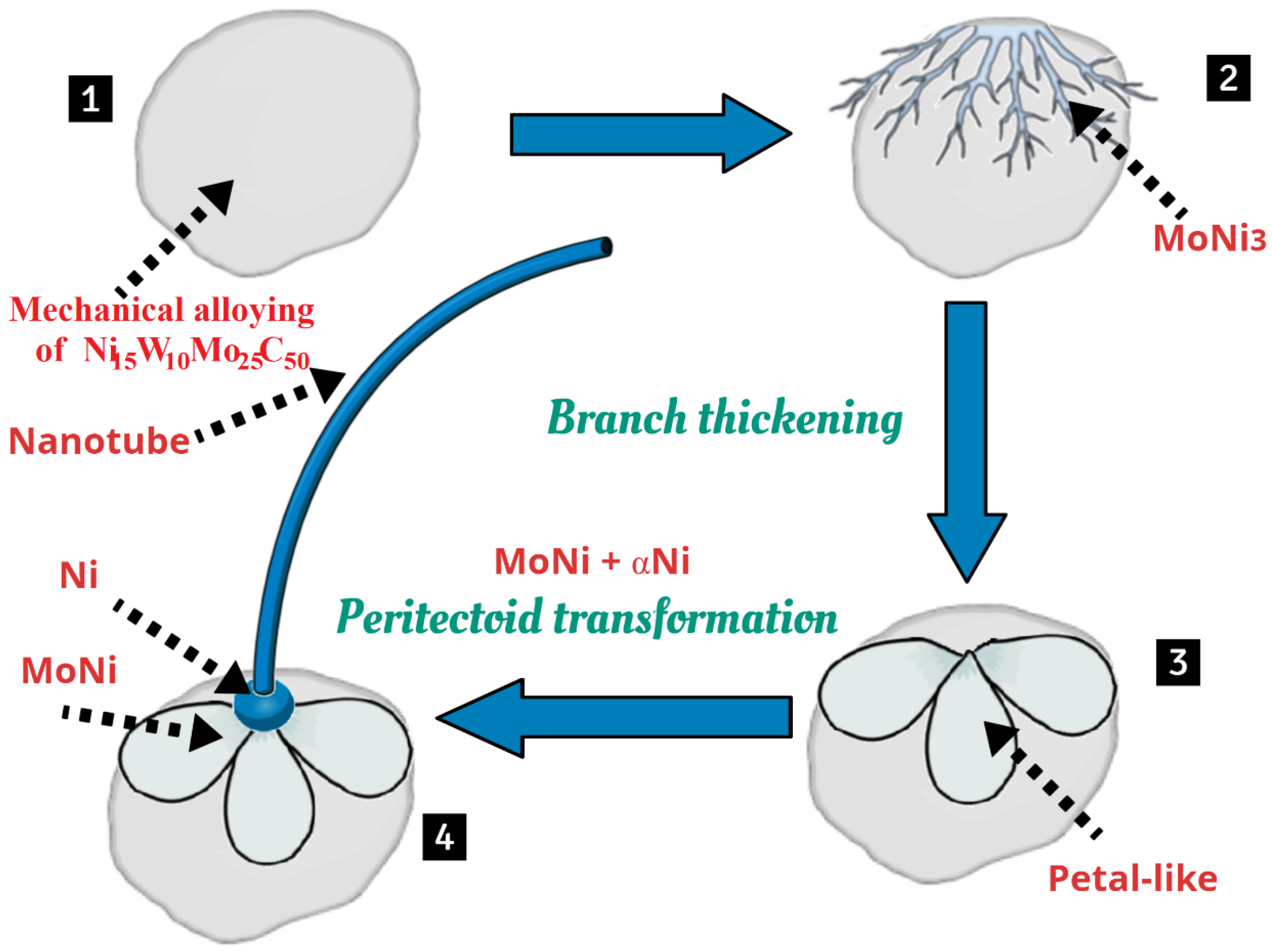
3. Results and Discussion

Figure 2a shows X-ray diffraction (XRD) results for the sample milled at 180 h. The obtained phases were C, Ni, WMoC, and NiC. Figure 2b shows the X-ray diffraction (XRD) pattern of the quenched NiWMoC powders. The results revealed the presence of MoNi 3 , WMo, Ni 4 W, WC, MoNi and Mo 2 C. Some of the diffraction peaks observed for the heat-treated metallic carbide powders were not detected in the corresponding XRD pattern of the sample obtained by milling (Figure 2a). This suggests the occurrence of WMoC-NiC decomposition. Previously, we prepared the same system under different synthesis conditions, and this kind of decomposition was not observed [26,27], indicating that the crystal deformation conditions used in this work, namely 180 h of milling, followed by sintering, heat treatment, and quenching, supply the energy for the decomposition of the milled phases and therefore the formation of new phases during sintering and quenching. Table 1 summarizes the crystallographic data of the phases obtained by mechanical milling and quenching.
Figure 3a presents the SEM images showing the morphology of the unmilled sample. The characteristic morphology of the initial powder was flake-like with an average size of 18 µm. After milling for 180 h, the powder particle size decreased considerably due to work hardening and fracture via a fatigue mechanism [28]. An average particle size of approximately 4 µm was obtained after 180 h of milling (Figure 3b).
Figure 4 shows the SEM micrographs of the quenched sample. Phase separation due to a decomposition mechanism in a flake-like carbide is shown in Figure 4a. The dark flake-like shape corresponded to the carbide phase, while the bright branch-shaped structure corresponded to the intermetallic MoNi 3 phase based on the chemical composition of this region. The results of the EDS point chemical analysis from the yellow selected area Figure 4a are presented in Table 2 (Spot 1). This region had an atomic composition of 73.34 at.% Ni, 22.98 at.% Mo, 2.67 at.% C, and 0.98 at.% W with slight oxidation. It must be noted that decomposition was related to a spontaneous separation of phases, and the interdiffusion process increased when the phases interacted with each other. This interaction can be attributed to the mechanical energy produced by mechanical alloying (MA) that leads to the deformation process in the powder particles during the mechanosynthesis process according to the literature [18]. Then, the formation of stable nuclei and their boundaries is forbidden, leading to the formation of a branch-shaped structure. Branched structures are formed when an energy gradient affects a specific region of the separated phase by decomposition that leads to regions rich in one phase intercalated with regions rich in another phase [29,30]. Figure 4b shows the formation of globular carbide particles with the diameters of approximately 500 nm (darkest zone). In these particles, decomposition and the formation of nanotubes were observed. Under the tubes, a branched bright pattern was observed. However, in one of these particles, instead of branched structures, the bright regions had a “petal-like”shape, which is probably evidence of a decomposition mechanism [31].
EDS analysis of Spot 2 (shown in Figure 4b and Table 2) indicated the presence of Mo, Ni, C, and W with a very low atomic percentage of oxygen in the central particle, where the phase contrast was very clear, and the structures were modulated in petal-like shapes. Notably, a nanotube emerged from a small core located between this same nanotube and the petal structures (see Figure 4b). Since MoNi 3 was detected in XRD results (see Figure 2b), this phenomenon may be attributed to a peritectoid transformation in which MoNi 3 was separated into the α Ni + MoNi phase [19]. The decomposition of the MoNi 3 phase can explain the clear separation of the carbon from the MoNi intermetallic phase at the nanotube base (see Figure 4b). This separation occurs due to segregation phenomena during quenching [29] and possibly involves a ferromagnetic–diamagnetic interaction between nickel and carbon. Another reason for the separation of MoNi and carbon is the poor solubility of Ni in graphite at the heat treatment temperature used in work [32]. Interestingly, as observed in Figure 4b, the nanotube that emerged is not morphologically similar to the spiral structure shape that also emerges from a particle, as shown in Figure 4d. Figure 4c shows that a large number of nanotubes with different lengths were produced that had an average length of approximately 1 μ m. The results of the EDS analysis of this region (see Table 2 for the results obtained from Spot 3 in Figure 4c) indicated that the highest composition fraction was due to carbon. It is known that the length and diameter of nanotubes depend on several physical and chemical parameters, and the reason for the production of nanotubes with a variety of lengths remains unknown [33]. It is necessary to analyze the base of the nanotubes shown in this work to research the role of its support; we will investigate this in future work. It is known that SEM images depend strongly on the properties and chemical composition of the samples. For example, Figure 4 shows petal-like, globular, spheres and branched structures which are brighter than the rest of the area in the micrographs. Table 2 lists the chemical composition of these structures. According to Egerton, this is due to the fact that secondary electron (SE) emission in the SEM is reduced, and many of the secondary electrons are attracted back to the sample surface and the bright zones occur most likely due to the surface charge that accumulates at the edges and ridges of materials that are not sufficiently electrically conductive [34]. Therefore, this sample is associated with the formation of intermetallic globe-like structures with homogeneous phases in brighter particles (see Figure 4d). However, one-dimensional structures with spiral-like shapes were also observed, which tend to be brighter when they are in touch (between globe-like structure and spiral structure, see Figure 4d). These spiral structures had closed ends, suggesting that they are components of some nanotube-type structure. The EDS results for the globule-like structures showed that they were composed mostly of Mo, W, and Ni (see Figure 4d and Table 2, Spot 4). We also observed the formation of triangular prisms (see Figure 4e), which, according to the EDS point chemical analysis from Spots 5 and 6 (see Figure 4e,f) are rich in C and W, corresponding to the C (Spot 5) and WC (Spot 6) phases with crystal structures in the hexagonal and trigonal systems, respectively. Notably, this prism displayed a graphite crystal with triangular terrace shapes (shown in Figure 4e). Figure 4f shows spheres with diameters ranging from 40 to 600 nm. The strong contrast among these spheres indicates heterogeneous phases, suggesting that the brightest spheres corresponded to intermetallic phases and the darkest spheres were carbide phases. This is confirmed by EDS results shown in Table 2 for Spots 7 and 8. The darkest one is composed of 72.56% and 27.26% of C and W, respectively, and the brighter sphere is composed mostly of Ni and Mo. The production of the spheres showed in Figure 4f is related to the formation of small droplets during heating the powder particles at 900 °C leading to their coalescence and increasing the diameter and size of the spheres through Ostwald ripening. Zhang et al. demonstrated theoretically that it is possible to obtain this morphology in a decomposition mechanism [35]. Their simulations showed that the evolution patterns (morphology) in decomposition at the very beginning stage of the phase decomposition into two separated phases deviate slightly, but at longer times of heating, the parent structure starts to break up and gradually can form spherical droplets due to surface tension [35].
Figure 5 shows the evolution of the phases and the formation of the petal-like structure of Ni 15 Mo 25 W 10 C 50 after quenching. Examination of SEM images suggests that the transformation mechanism for the production of these petal-like structures can be proposed as follows: (1) production of WMoC-NiC-Ni-C (Table 1) with flake-like morphology during mechanical alloying of Ni 15 Mo 25 W 10 C 50 at 180 h (see Step 1 in Figure 5); (2) formation of the MoNi 3 intermetallic phase caused by a decomposition mechanism (see Step 2 in Figure 5); (3) branch thickening of the MoNi 3 intermetallic to produce the petal-like structure (see Step 3 in Figure 5); (4) transformation of MoNi 3 to MoNi + α Ni caused by peritectoid decomposition in addition to the nanotubes emerged from this particle due to the repulsion between the intermetallic phase and carbon (see Step 4 in Figure 5). If we compare EDS elemental composition (shown in Table 2) against the Mo-Ni phase diagram during heating process [36], the MoNi 3 phase tends to move to the MoNi + Ni region; therefore, XRD results confirm the presence of these decomposed phases (see Figure 2b and Table 1). Isostructural transformation is an important characteristic during the decomposition mechanism; it is evident that none of the phases identified after mechanical alloying or quenching correspond to the parent of the MoNi 3 phase (as observed in Table 1). This behavior is due to an intermediate parent phase (which is unknown), which was produced between the sintering and the quenching process. We think that potential applications of the samples observed in this work can be extended to additional catalysts if the preparation of these materials is properly controlled. For example, in Figure 4b, the petal-like structured particle has a modulated ferromagnetic MoNi phase on its surface. These petal-like structures are separated from each other and resemble commutators of direct current (DC) in motors and generators. It is possible that when introduced into a magnetic field, this particle rotates and acts as a motor and can act as a generator. This application may be attractive for use in generator/motor microelectromechanical systems MEMS [37].

4. Conclusions

In the present work, mechanical alloying of Ni 15 Mo 25 W 10 C 50 was carried out, and the following phases were found after grinding at 180 h: Ni, C, WMoC and NiC. After quenching, XRD confirmed the presence of graphite (31.14% wt.), hexagonal WC (23.44% wt.), WMo (16.04% wt.), MoNi 3 (12.44% wt.), Mo 2 C (8.00% wt.), Ni 4 W (7.46% wt.), MoNi (1.16% wt.) and Ni (0.32% wt.). A decomposition mechanism similar to spinodal occurred during the synthesis process, leading to the generation of MoNi 3 and Ni 4 W phases with branched-like morphologies, microparticles, and petal-like shapes in microparticle structures. As this decomposition developed very quickly and occurred followed by several phase transformations, no evidence of the isostructural transformation typical of spinodal decomposition could be observed. Based on SEM observations, we proposed that MoNi 3 transformation into α Ni and MoNi is due to the peritectoid transformation, and this transformation promotes nanotube formation. According to the results of this work, nanotube growth is promoted when a carbide system has enough energy and favorable thermal conditions for decomposition. It is possible that the formation of α Ni ferromagnetic particles forms nanotubes with fewer imperfections due to the repulsion between the ferromagnetic metal and diamagnetic carbon. Curved nanotubes were observed tending to spiral-like shape structures in the samples with low atomic percent of Ni and where particles did not present a high decomposition fraction. As additional evidence of decomposition, the nucleation of globular intermetallic structures and the formation of triangular WC prisms were observed. Future research on the interplay between decomposition mechanism and nanotube formation behavior is needed.

Author Contributions

Methodology, data curation, investigation, draft preparation, writing—review and editing, project administration, J.N.R.O.; conceptualization, formal analysis, investigation, resources, supervision, review and editing, L.G.D.B.A.; visualization, L.H.M. All authors have read and agreed to the published version of the manuscript.

Funding

This work was supported by the Tecnológico Nacional de México TecNM, Campus Ixtapaluca. TESI, under grant No. 14050.22-PD and the Research Work TECNM-CA-TESI-Materiales Nanoestruturados. The authors thank CONAHCyT for its distinction and encouragement as a national researcher program SNI.

Data Availability Statement

XRD raw data for the milled, quenched sample shown in Figure 2 and EDS spectra from Figure 4 can be downloaded at: https://doi.org/10.6084/m9.figshare.24939480.v1.

Acknowledgments

J.N.R.O. would like to thank Christian Schulz for his support in this work.

Conflicts of Interest

The authors declare no conflict of interest.

References

  1. Kostorz, G. Phase Transformations in Materials; Wiley-VCH: Weinheim, Germany, 2001; Chapter 6; ISBN 3527302565. [Google Scholar]
  2. Vvedensky, D.D. Transformations of Materials; IOP Publishing: Bristol, UK, 2019; ISBN 1643276212. [Google Scholar]
  3. Jurgen Buschow, K.H.; Cahn, R.W. Encyclopedia of Materials: Science and Technology; Elsevier Publishing: Amsterdam, The Netherlands, 2001; ISBN 978-0-08-043152-9. [Google Scholar]
  4. Reedijk, J.; Poeppelmeier, K. Comprehensive Inorganic Chemistry II, 2nd ed.; Elsevier Publishing: Amsterdam, The Netherlands, 2013; ISBN 978-0-08-096529-1. [Google Scholar]
  5. Rudraraju, S.; Van der Ven, A.; Garikipati, K.T. Mechanochemical spinodal decomposition: A phenomenological theory of phase transformations in multi-component crystalline solids. NPJ Comput. Mater. 2016, 2, 16012. [Google Scholar] [CrossRef]
  6. Sun, L.; Vasina, R.N.; Islamov, A.K.; Bobrikova, I.A.; Sumnikova, S.V.; Balagurov, A.M.; Guo, W.; Cheng, W.C.; Golovin, I.S. Spinodal decomposition in ternary Mn-Cu-Cr alloy and its influence on martensitic transition temperatures. J. Alloys Comp. 2021, 884, 161082. [Google Scholar] [CrossRef]
  7. Zhou, X.; Kamachali, R.D.; Boyce, B.L.; Clark, B.G.; Raabe, D.; Thompson, G.B. Spinodal Decomposition in Nanocrystalline Alloys. Acta Mater. 2021, 221, 117054. [Google Scholar] [CrossRef]
  8. Chen, W.; Yu, G.; Li, K.; Wang, Y.; Zhang, J.; Sun, J. Plastic instability in Ti–6Cr–5Mo–5V–4Al metastable β-Ti alloy containing the β-spinodal decomposition structures. Mater. Sci. Eng. A 2021, 811, 141052. [Google Scholar] [CrossRef]
  9. Velázquez, D.; Chaparro, M.A.E.; Böhnel, H.N.; Romero, R.; Lanzini, F. Spinodal decomposition, chemical and magnetic ordering in Cu–Al–Mn shape memory alloys. Mater. Chem. Phys. 2020, 246, 122793. [Google Scholar] [CrossRef]
  10. Schultz, A.H.; Stubican, V.S. Modulated structures in the system TiO2-SnO2. Philos. Mag. 1968, 18, 155. [Google Scholar] [CrossRef]
  11. Xiao, Y.; Hwanga, J.; Sun, Y. Transition metal carbide-based materials: Synthesis and applications in electrochemical energy storage. J. Mater. Chem. 2016, 4, 10379–10393. [Google Scholar] [CrossRef]
  12. Shahzad, F.; Iqbal, A.; Kim, H.; Koo, C.M. 2D Transition Metal Carbides (MXenes): Applications as an Electrically Conducting Material. Adv. Mater. 2020, 32, 2002159. [Google Scholar] [CrossRef]
  13. Li, Z.; Wu, Y. 2D Early Transition Metal Carbides (MXenes) for Catalysis. Nano micro-Small. Adv. Mater. 2019, 15, 1804736. [Google Scholar]
  14. Vasilevich, A.V.; Baklanova, O.N.; Lavrenov, A.V. Molybdenum Carbides: Synthesis and Application in Catalysis. Solid Fuel Chem. 2020, 54, 354–361. [Google Scholar] [CrossRef]
  15. Plata, F.J.C.; Olvera, J.N.R.; Febles, V.G.; Barriga, L.G.D. Thermodynamic analysis and microstructural evolution of the W-Mo-Ni-C system produced by mechanical alloying. Phys. B Phys. Cond. Matt. 2022, 644, 414126. [Google Scholar] [CrossRef]
  16. Pierson, H.O. Properties, Characteristics, Processing and Applications (Materials Science and Process Technology; William Andrew Publishing: Norwich, NY, USA, 1996; ISBN 978-0815513926. [Google Scholar]
  17. Patel, P.; Kim, I.S.; Kumta, P.N. Nanocomposites of silicon/titanium carbide synthesized using high-energy mechanical milling for use as anodes in lithium-ion batteries. Mater. Sci. Eng. B 2005, 116, 347–352. [Google Scholar] [CrossRef]
  18. Suryanarayana, C. Mechanical alloying and milling. Progress in Materials Science. Prog. Mater. Sci. 2001, 46, 1–184. [Google Scholar] [CrossRef]
  19. Díaz-Barriga Arceo, L.; Rendón-Vázquez, L.; Orozco, E.; Garibay-Febles, V.; Palacios Gonzalez, E.; Leyte Guerrero, F. Nanotubes Obtained from Mono and Bimetallic Carbides Produced by Mechanical Alloying. Mater. Sci. Forum. 2007, 539–543, 2731–2736. [Google Scholar] [CrossRef]
  20. Padmanaban, D.B.; Mohan, L.; Giri, P.; Bera, P.; An an, C.; Barshilia, H.C. Effect of Molybdenum Content on Mechanical and Tribological Properties of Diamond-Like Carbon Coatings over Titanium β-21S Alloy. J. Carbon. Res. 2021, 7, 1. [Google Scholar] [CrossRef]
  21. Czaplicka, N.; Rogala, A.; Wysocka, I. Metal (Mo, W, Ti) Carbide Catalysts: Synthesis and Application as Alternative Catalysts for Dry Reforming of Hydrocarbons—A Review. Int. J. Mol. Sci. 2021, 22, 12337. [Google Scholar] [CrossRef]
  22. Bao, X.; Wang, T.; Yang, Y. Recent progress in bimetallic carbide-based electrocatalysts for water splitting. Mater. Chem. Front. 2024. [Google Scholar] [CrossRef]
  23. Balbino, N.A.N.; Correa, E.O.; Huanca, D.R.; Flávio Amaury de Freitas Matos and Livio de Carvalho Valeriano. Comparative Study of Corrosion Behaviors of WC-NiMo and WC-Co Cemented Carbides. Materials 2023, 16, 4480. [Google Scholar] [CrossRef]
  24. JOlvera, e.N.R.; Gutiérrez, J.; Serrano, J.A.R.; Ovando, M.; Febles, V.G.; Arceo, L.D.B. Use of unsupported, mechanically alloyed NiWMoC nanocatalyst to reduce the viscosity of aquathermolysis reaction of heavy oil. Catal. Commun. 2014, 43, 131–135. [Google Scholar] [CrossRef]
  25. Cullity, B.D.; Stock, S.R. Elements of X-ray Diffraction; Prentice Hall: Englewood Cliffs, NJ, USA, 2001; ISBN 0201610914. [Google Scholar]
  26. Martinez Ruiz, M.; Rivera Olvera, J.N.; Morales Davila, R.; González Reyes, L.; Garibay Febles, V.; Garcia Martinez, J.; Diaz Barriga Arceo, L.G. Synthesis and Characterization of Mechanically Alloyed, Nanostructured Cubic MoW Carbide. Appl. Sci. 2020, 10, 9114. [Google Scholar] [CrossRef]
  27. Olvera, J.N.R.; Paredes, G.G.; Serrano, A.R.; López, E.R.; Franco, E.M.; Meza, P.T.; Arceo, L.D.B. Synthesis and characterization of a MoWC-WC-NiC nanocomposite via mechanical alloying and sintering. Powder Technol. 2015, 271, 292–300. [Google Scholar] [CrossRef]
  28. Akbarpour, M.R. Effects of mechanical milling time on densification, microstructural characteristics and hardness of Cu–SiC nanocomposites prepared by conventional sintering process. Mater. Chem. Phys. 2021, 261, 124205. [Google Scholar] [CrossRef]
  29. Porter, D.A.; Easterling, K.E.; Sherif, M.Y. Phase Transformations in Metals and Alloys; CRC Press: Boca Raton, FL, USA; Taylor and Francis Group LLC: New York, NY, USA, 2009; Chapter 5; pp. 302–309. ISBN 9781420062106. [Google Scholar]
  30. Carter, C.B. Solid-State Phase Transformations and Reactions. In Ceramic Materials; Springer: New York, NY, USA, 2007; ISBN 978-0-387-46271-4_25. [Google Scholar]
  31. Illescas, C.R.E. Analysis of Phase Separation in Aged Alloys by the Phase Field Method. Master’s Thesis, National Polytechnic Institute of Mexico, Mexico City, Mexico, 2018; p. 112, Figure C. Available online: https://tesis.ipn.mx/handle/123456789/25979 (accessed on 3 January 2024).
  32. C-Ni Phase Diagram. Available online: https://www.crct.polymtl.ca/fact/phase_diagram.php?file=C-Ni.jpg&dir=SGTE2014 (accessed on 3 January 2024).
  33. Corletto, A.; Shapter, J.G. Nanoscale Patterning of Carbon Nanotubes: Techniques, Applications, and Future. Adv. Sci. 2021, 8, 2001778. [Google Scholar] [CrossRef] [PubMed]
  34. Egerton, R.F. Physical Principles of Electron Microscopy: An Introduction to TEM, SEM, and AEM; Springer Publishing: Berlin/Heidelberg, Germany, 2016; ISBN 978-3319398761. [Google Scholar]
  35. Zhang, L.; Peng, Y.; Zhang, L.; Lei, X.; Yao, W.; Wang, N. Temperature and initial composition dependence of pattern formation and dynamic behavior in phase separation under deep-quenched conditions. RSC Adv. 2019, 9, 10670–10678. [Google Scholar] [CrossRef]
  36. Mo-Ni Phase Diagram. Available online: http://www.factsage.cn/fact/phase_diagram.php?file=Mo-Ni.jpg&dir=SGTE (accessed on 3 January 2024).
  37. Mitcheson, P.D.; Miao, P.; Stark, B.H.; Yeatman, E.M.; Holmes, A.S.; Green, T.C. MEMS electrostatic micropower generator for low frequency operation Green. Sens. Actuators A 2004, 115, 523–529. [Google Scholar] [CrossRef]
Figure 1. Schematic diagram of the process.
Carbon 10 00011 g001
Figure 2. (a) Sample milled at 180 h and (b) the XRD pattern of NiWMoC of the quenched sample.
Carbon 10 00011 g002
Figure 3. SEM micrographs of the (a) unmilled (mixed) sample and (b) sample milled for 180 h.
Carbon 10 00011 g003
Figure 4. SEM micrographs of the quenched sample, (a) decomposition in the lamellar structure, (b) SD in carbide microparticles, (c) nanotubes, (d) nanoparticles with spiral tubes, (e) triangular growth of graphite and triangular prism of WC and (f) micro- and nanospheres of metal carbides and intermetallic phase with Ostwald ripening phenomena.
Carbon 10 00011 g004
Figure 5. Theoretical model of steps of modulated structure formation.
Carbon 10 00011 g005
Table 1. Crystallographic data of the milled (M) and quenched samples (Q).
Phases (M—Milled and Q—Quenched)Crystalline StructureLattice Parameter (nm)Phase Percentage %ICDD Card *
W M o C M Cubica = 0.314870.28Ref. [26]
C M Hexagonala = 0.2464, c = 0.673620.26120212
N i M Cubica = 0.35238.96040850
N i C M Cubica = 0.35390.50140020
W C Q Hexagonala = 0.2900, c = 0.283123.44654539
W M o Q --16.04Unknown
M o N i 3 Q Orthorhombica = 0.5064, b = 0.4224, c = 0.444812.44652587
M o N i Q Orthorhombica = 0.9128, b = 0.9134, c = 0.88351.16481745
N i Q Cubica = 0.35230.32040850
M o 2 C Q Hexagonala = 0.3012, c = 0.47358.00350787
N i 4 W Q Tetragonala = 0.5730, c = 0.35537.46652673
C Q Hexagonala = 0.2464, c = 0.673631.14120212
* International Centre for Diffraction Data.
Table 2. EDS results for the spot in the SEM images shown in Figure 4.
SEM–EDS * (Figure 4)C (at.%)Mo (at.%)Ni( at.%)W (at.%)O (at.%)Fe (at.%)
Spot 12.67 ± 0.0422.98 ± 0.4173.34 ± 0.840.98 ± 0.090.23 ± 0.01-
Spot 212.18 ± 0.1366.48± 0.5415.99± 1.025.22 ± 0.010.13 ± 0.04-
Spot 397.42 ± 0.750.95 ± 0.010.32 ± 0.020.44 ± 0.010.87 ± 0.03-
Spot 41.26 ± 0.0365.78 ± 1.6414.05 ± 0.6718.91 ± 0.86--
Spot 593.80 ± 2.01-0.99 ± 0.014.35 ± 0.220.35 ± 0.020.51 ± 0.04
Spot 678.15 ± 1.784.10 ± 0.52-17.58 ± 0.750.17 ± 0.02-
Spot 772.56 ± 1.570.18 ± 0.03-27.26 ± 0.75--
Spot 81.04 ± 0.0134.3 ± 0.4364.52 ± 0.74--0.14 ± 0.04
* EDS spectra can be downloaded, please check the data availability section.
Disclaimer/Publisher’s Note: The statements, opinions and data contained in all publications are solely those of the individual author(s) and contributor(s) and not of MDPI and/or the editor(s). MDPI and/or the editor(s) disclaim responsibility for any injury to people or property resulting from any ideas, methods, instructions or products referred to in the content.

