Article

Analysis of Electromagnetic Shielding Properties of Cement-Based Composites with Biochar and PVC as Fillers

1
Department of Engineering and Applied Sciences, Università di Bergamo, 24044 Dalmine, Italy
2
Department of Electronics and Telecommunications, Politecnico di Torino, 10129 Turin, Italy
*
Author to whom correspondence should be addressed.
Submission received: 29 November 2023 / Revised: 21 February 2024 / Accepted: 26 February 2024 / Published: 1 March 2024
(This article belongs to the Section Carbon Materials and Carbon Allotropes)

Abstract

:
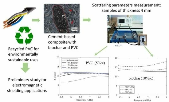
Biochar (bio-charcoal) is a low-cost and eco-friendly material. It can be obtained by thermochemical conversion of different biomass sources, for example, in the total absence of oxygen (pyrolysis) or in oxygen-limited atmosphere (gasification). The porous carbonaceous structure of biochar, resulting from the thermal treatment, can be exploited in cement-based composite production. By introducing biochar powder or other fillers in the cement paste, it is possible to enhance the shielding properties of the cement paste. The environmental impact of polyvinyl chloride (PVC) can be reduced by reusing it as a filler in cement-based composites. In this work, cement-based composites filled with different percentages of biochar and PVC are fabricated. The scattering parameters of samples with 4mm thickness are measured by mean of a rectangular waveguide in the C-band. The shielding effectiveness of reference samples without any filler and samples with biochar and PVC is analyzed. A combination of 10 wt.% biochar and 6 wt.% PVC provides the best shielding performance (around 16 dB).

Graphical Abstract

1. Introduction

The increasing number of radio frequency (RF) sources in recent years has focused attention on materials that can avoid the effects associated with exposure to electromagnetic waves produced by these types of sources [1]. In both indoor and outdoor environments, problems due to exposure to several RF sources (WiFi, Bluetooth, and others) and interference between various devices are increasing [2]. Excessive exposure to this type of radiation is harmful to human health by increasing the likelihood of cancers and other diseases [3,4]. Biological systems and tissues absorb non-ionizing electromagnetic radiation, causing molecule vibration and thus heating [5,6]. Therefore, materials for electromagnetic interference (EMI) protection have attracted considerable research attention for the construction sector [7,8,9,10].
Shielding in buildings is traditionally achieved through metal sheets which can absorb, reflect, and refract the electromagnetic waves [11]. Cement-based materials have poor EMI protective characteristics [12]. By introducing into the cement paste conductive fillers, it is possible to improve the shielding or absorption of electromagnetic waves [13]. The most widely used fillers are metals [14] and carbon-based materials ([13,15,16,17,18]).
The cement industry is a large consumer of energy and raw materials. The necessity for utilizing waste materials is increasingly evident [19]. Increasing energy efficiency and using industrial waste instead of raw materials can contribute to eliminating these problems, and its addition into cement pastes made from such waste can have electrical and mechanical properties similar to those of pure Portland cements at a lower cost per unit volume [20].
In the search for eco-friendly and cost-effective materials capable of electromagnetic shielding in buildings, biochar/cement-based composites have proved to be a viable option [10,21,22,23]. Moreover, these types of composite materials are only slightly different from the materials currently used in the construction industry, making their introduction into the construction sector easier.
Biochar is a material obtained by thermochemical conversion of different bio-masses in an oxygen-limited atmosphere at temperatures < 750  ° C [24,25]. Biochar properties are strongly related to the biomass source, which includes biological residues from agriculture (vegetable and manure), forestry (wood), and the biodegradable fraction of sewage sludge [26,27]. The biomass used for the production of biochar is converted into a stable carbon fraction, thus being removed from the natural degradation that would lead to the emission of greenhouse gases. Moreover, cement-based composites filled with biochar showed an improvement in mechanical properties with respect to traditional cements [28,29].
Replacing small amounts of cement (0.5 wt.% to 2 wt.%) with wood biochar in concrete improves compressive strength, which reaches values of 68.93 MPa when the amount of biochar added is 0.5 wt.% [30]. The development of compressive strength is related to the hydration product C-S-H; the high carbon content of biochar reduces the formation of C-S-H, and excessive incorporation, greater than 5 wt.% of biochar, causes a decrease in compressive strength [31]. In [32], the exploitation of biochar in cement pastes allowed for the bending and compressive strengths to be improved by 10.3%. In [33], an increase was observed in the flexural strength, indicating an improvement in the fracture energy. A similar mechanical property enhancement with respect to the control group was described in [34]. The compressive strength and flexural strength increase with moderate biochar addition.
Recently, polyvinyl chloride (PVC) fibers, generally used in medical applications [35] or in construction [36], were introduced in cement-based composites [37,38]. PVC from electrical cable sheaths is a waste material produced in large quantities. Additives, such as heat and light stabilizers, lubricants, fillers, coloring pigments, and possibly plasticizers, are added to it to make it suitable for electrical cables. The use of PVC fiber in cement-based composites for SE can, among other things, help reduce the problem of solid waste management. Few studies deal with the use of PVC fibers in cement-based composites, although it is known that the incorporation of PVC fiber in cement influences the texture, high fiber stiffness, and strong fiber matrix bonding [39]. For example, the maximum increase in compressive strength is 30.8% with the addition of 0.8% PVC fiber [26,27]. An interesting paper by Merlo et al. [40] investigated the suitability of using PVC derived from the sheath of electrical cables as substitutive aggregate in the production of mortars. An increase in PVC content at 10 % vol to natural aggregate tends to decrease the 28-day compressive strength by around 50%.
Depending on the sample size and on the desired frequency band, shielding effectiveness can be measured with several methods; the most common are waveguide methods [15,41,42,43], free-space methods [44], and using a reverberation chamber [45]. SE can also be evaluated based on the knowledge of the material permittivity [42,46] or using prediction models [47].
Several studies highlighted the possibility of improving the shielding performances with carbonaceous materials/cement-based composites [48]. Dispersion of colloidal graphite at 0.92 vol.% in a cement matrix composite obtained a shielding effectiveness (SE) at 1 GHz of 22.3 dB [49]. In that study, it is also reported that the SE of cement-based composites with 0.5 vol.% carbon filament was 28.7 dB at 1 GHz. The SE of a cement-based composite with 0.84 vol.% carbon fiber was 15 dB at 1.5 GHz [50]. Dispersion of 15 wt.% multi-walled carbon nanotubes (MWCNTs) in the cement-based matrix produces an SE more than 27 dB in the X-band (8.2–12.4 GHz), and this SE is found to be dominated by absorption [51]. Microwave-absorbing shielding analyses of reinforced concrete were conducted by many authors [52,53,54]. Regarding the SE properties of PVC chopped fiber/cement-based composites, some studies were carried out concerning ionizing radiation [14,55,56,57]. Some authors analyzed the effects of PVC in combination with other elements [58,59,60,61] but no document was found in the scientific literature dealing with the analysis of shielding properties of PVC and biochar at the microwave frequency.
In this paper, PVC and lignin-based commercial biochar were used as a partial substitute to cement in cement-based composites. Previous works by the same authors studied the shielding capabilities of cement-based composites filled with biochar only [22,23]. In this work, we want to perform a preliminary analysis on the shielding performance of cement-based composites with PVC and biochar as filler. The used PVC is obtained from the decommissioning of old electrical cables. The goal is to understand whether the shielding capabilities remain satisfactory, allowing recovery of PVC that would otherwise be destined for a landfill. Samples with various contents of filler (biochar and PVC) waraere made with specific dimensions and the SE was measured with the waveguide method (frequency band 5.4 GHz–8 GHz).
In Section 2, the preparation of cement-based composites is described and the shielding effectiveness is defined. In Section 3, after the micro-structural analysis, the shielding effectiveness of various composites is discussed. In Section 4, some conclusions are drawn.

2. Materials and Methods

2.1. Raw Materials

The reference cement matrix was made of ordinary-grade 52.5 R Portland cement (PC), compliant with ASTM C150 requirements [62], water, and superplasticizer (Giovanni Bozzetto S.p.A. SPT 100/ NL I1-0000167800). Two types of fillers were used:
-
Commercial biochar from Carlo Erba Reagents, originated from wood pyrolysis. Before use, biochar was thermally treated (reactivation process) in the oven for four hours at 750   ° C in a covered alumina crucible, filled to the brim so as to avoid combustion in presence of oxygen (see Figure 1a).
-
PVC was obtained from the sheathing of electrical cables by a granulating procedure, and sieved to separate the fraction with dimensions smaller than 1 × 10 3  m. Since PVC is derived from waste, the presence of a small amount of copper fragments can be observed, together with a filler mainly constituted by CaCO 3 , as discussed in Section 3.1. The size of the resulting PVC particles, after sifting, was below 2 × 10 3  m (see Figure 1b).

2.2. Composite Preparation

Composites of cement without any filler and samples with PVC and biochar as fillers were realized.
Biochar powder was mixed with PC, PVC, water, and a superplasticizer using a mechanical mixer. The mixing was performed for fifteen minutes until a homogeneous mixture was obtained. The superplasticizer guaranteed adequate workability of the sample. The composite was then poured into rectangular molds shaped to suit the requirement of the measurements of the scattering parameters and, consequently, the evaluation of the shielding effectiveness.
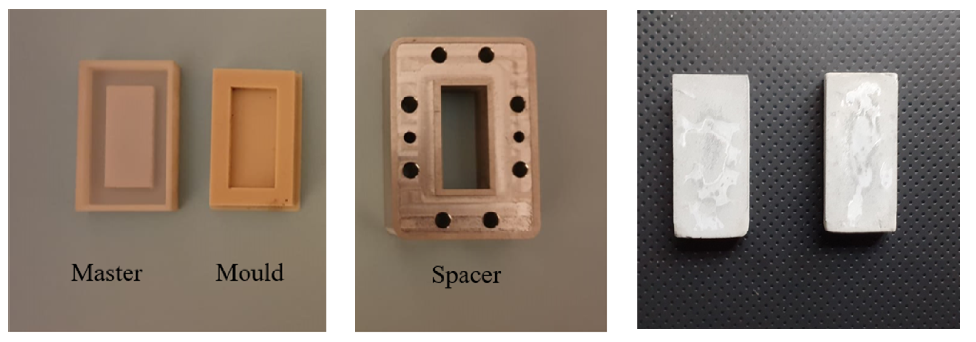
To realize samples fitting in the waveguide cross-section (nominal dimensions: 34.84   mm × 15.79   mm ), a 3D-printed master mold was first fabricated (3D Systems, Projet 2500 Plus). Then, several silicon (Prochima GLS-10) molds were realized (see Figure 2). Silicon molds are reusable and flexible. This helps in easy extraction of composite samples. All the sample thicknesses were 4 mm.
All the specimens were kept at 90 ± 5 % relative humidity (RH) for an initial 24 h. After that, the samples were demolded and immersed in water. The samples were cured in water at room temperature ( 20 ± 2   ° C) for a period of 14 days. After curing, the samples were stored in air under ambient conditions.
Composites with 5 % /c of PVC and different amounts of biochar ( 10 % /c, 12 % /c, 14 % /c) were realized. Samples with a 10 % /c constant biochar filler amount and different PVC weight fractions ( 3.5 % /c, 5 % /c, and 6 % /c) were also made. Furthermore, a reference set was prepared using only cement, water (35% by weight of PC), and superplasticizer (1.5% by weight of PC). The list of samples is reported in Table 1, where water %/c, superplasticizer %/c, biochar %/c, and PVC %/c are the weight fraction of water, superplasticizer, biochar, and PVC, respectively, with respect to cement weight. In the preparation of the samples with constant PVC and different percentages of biochar, it was not possible to keep this ratio constant as a result of (i) the high porosity of the biochar, and (ii) physisorption of the mixing water through H-bonding, as explained in Section 3.2. This problem does not arise in the case of samples with a constant weight percentage of biochar; these show a constant water %/c ratio.
The values in Table 1 are converted to the percentage in mass (m/m) and reported in Table 2.

2.3. Microstructural Analysis

Microstructural analysis of the samples was carried out using X-ray diffraction (XRD) and optical microscope imaging (Nikon, Tokyo, Japan). The powder XRD pattern of the sample was collected using a Bruker D8 Advance diffractometer equipped with a LynxEye XE detector (Bruker, Karlsruhe, Germany), with Cu-Ka radiation ( λ = 1.5406 Å). The diffraction data were collected in the 2 θ range 5–70°, with a step size of 0.011° 2 θ and counting time of 19.2 s per step. XRD allowed for the identification of crystalline phases in the PVC particles. Through an optical microscope, namely the Digital Microscope VHX 7100 (Keyence, Osaka, Japan), the digital imaging of the samples was performed. A color mode with 400× magnification was enhanced by a high-intensity ring-shaped LED lamp. The “3D shape correction” for depth profile correction was also exploited.

2.4. Shielding Effectiveness Definition

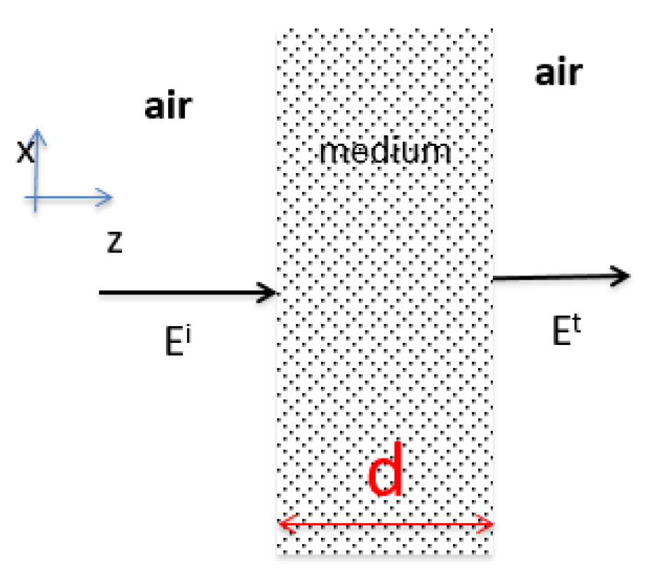
Consider a dielectric slab (medium 2) of thickness d in air, as shown in Figure 3. An electric field ( E i ) is incident from free-space (medium 1) onto the surface of the slab. The incident electric field on the left is partially reflected ( E r ), partly transmitted ( E t ) and absorbed. The shielding effectiveness (SE) is defined as the ratio between the incident and the transmitted electric field (in Volt per meter) as:
SE = E i E t
SE can also be expressed in terms of power, as follows:
SE = P i P t
where P i corresponds to the incident power in Watts, associated to the incident electric field E i , and P t corresponds to the transmitted power associated to the transmitted electric field.
Among the different methods, shielding effectiveness can be evaluated from the scattering parameters S i j measured in waveguides [42]. Consider a composite of given thickness d inserted in a rectangular waveguide. The longitudinal view of the waveguide with the sample inserted is schematically represented in Figure 4.
From the measured transmission coefficient ( S 21 ) in the waveguide, the SE can be defined as:
SE = 20 · l o g 10 S 21
The SE is the summation of two contributions:
SE = L D + L M
where L D is the dissipation loss, i.e., the attenuation of the incident field when passing through the slab; L M is the mismatch loss caused by reflection at the left and right interfaces. Both of them can be evaluated from the transmission ( S 21 ) and reflection coefficients ( S 11 ) as follows:
L D = 10 · l o g 10 | S 21 | 2 1 | S 11 | 2
L M = 10 · l o g 10 1 | S 11 | 2

2.5. Scattering Parameter Measurement Setup

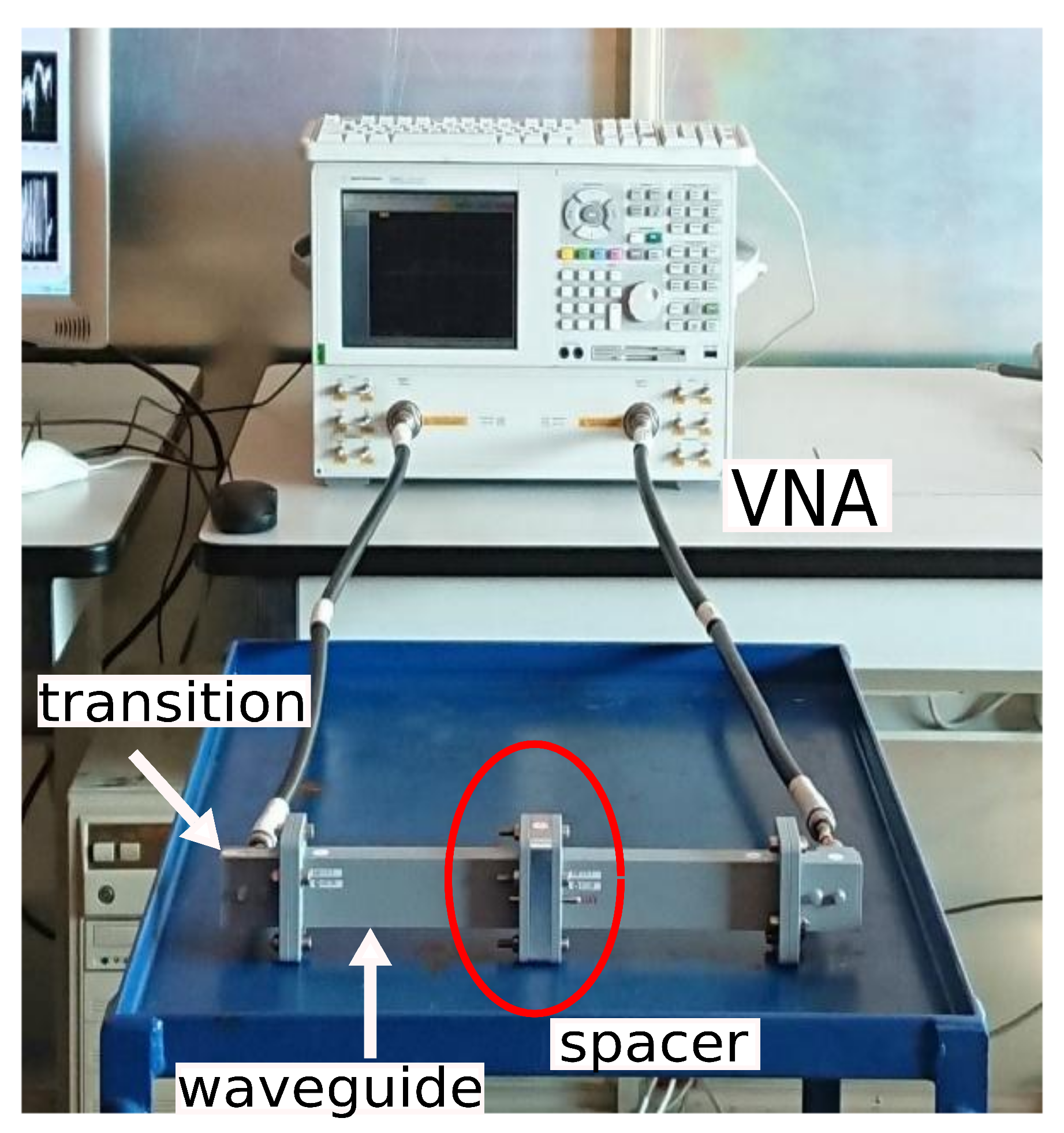
The scattering parameters of the cement-based composite samples are measured using a Network Analyzer (HP Agilent Keysight 8720B) (Keysight, Santa Clara, CA, USA) and a WR137 waveguide. The measurement setup is shown in Figure 5, where the ports of the VNA are connected by means of a coaxial-to-waveguide adapter, to a WR137 waveguide ( 34.85   ×   15.79 )   mm 2 , schematically analyzed in Figure 4. The samples are inserted in the waveguides by means of a waveguide spacer. The spacer is encircled in red. A standard calibration full 2-port is performed before each set of measurements in the frequency band from 5.4 to 8 GHz. The reference planes for the calibration process are set on the left and right sides of the spacer, respectively, as shown in Figure 4.

3. Results

3.1. Microstructural Analysis

For examining the microstructural properties of the composites and dispersion of the filler in the composite matrix, X-ray diffraction measurements and optical images were used.
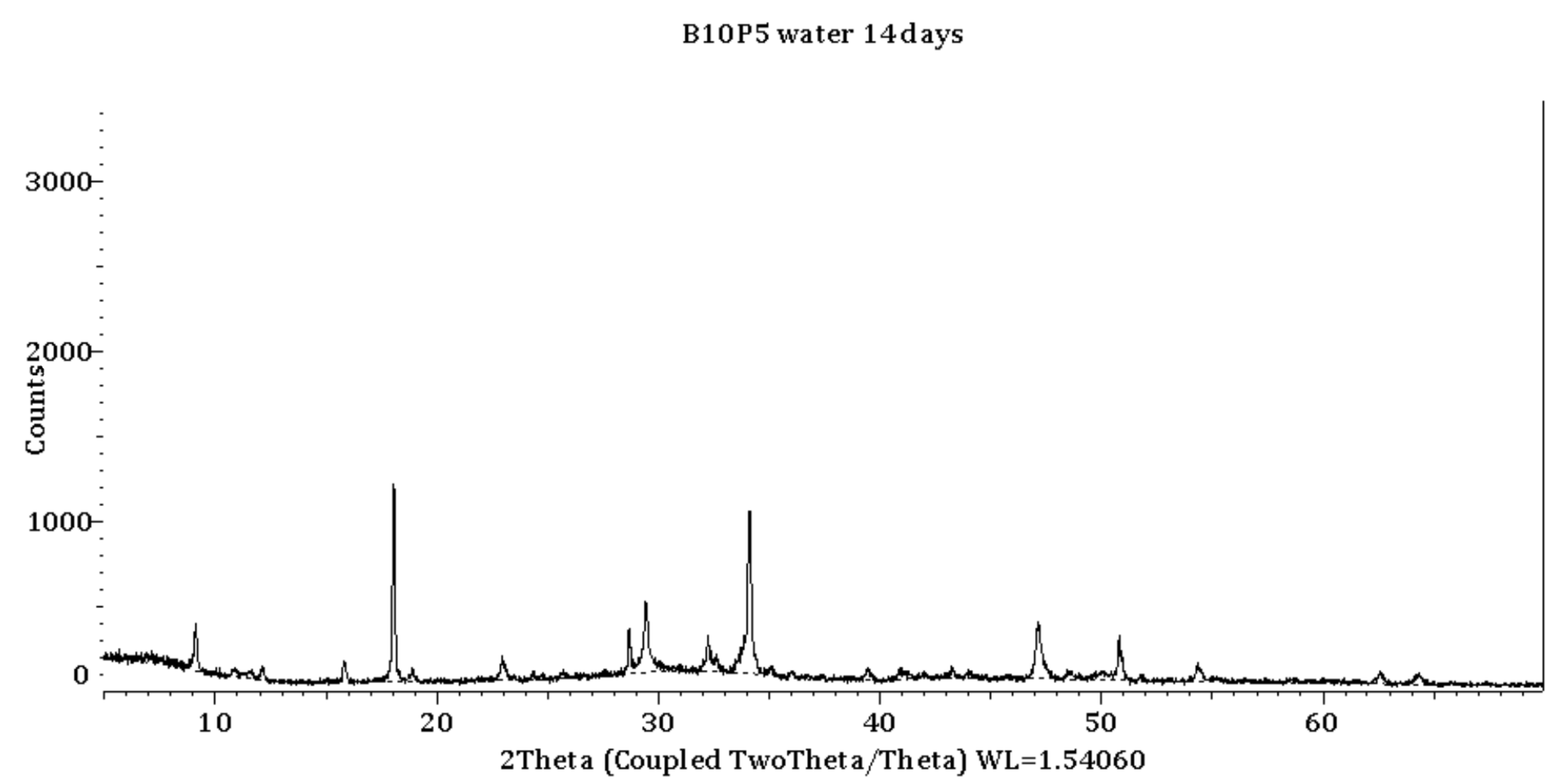
The XRD pattern in Figure 6 refers to granulated PVC after sieving. The pattern of PVC shows the diffraction peaks of calcite CaC O 3 (PDF 04-008-0198) and copper (PDF 00-004-0836) at 43.34° and 50.48°. CaC O 3 is used as a filler in PVC, and copper is a residue of the electrical conductor wire. The powder diffraction patterns from a 14-day-old sample are shown in Figure 7; alite, belite, calcite, and few products of hydration reactions, including calcium hydroxide, ettringite, and amorphous silicate hydrate (C-S-H), were identified. No evidence of products from chemical reactions of biochar or PVC was found.
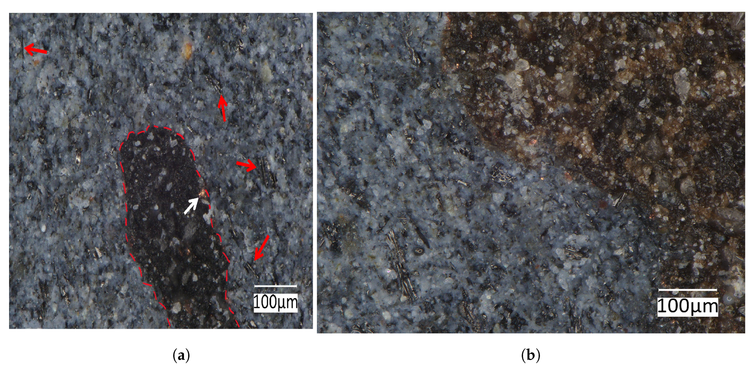
The characteristics of various cement-based samples were analyzed by means of optical microscope images. In Figure 8, the microstructure of a cement-based sample without any fillers is shown (reference sample). The compactness of the matrix and the big dimensions of the crystals can be observed. In Figure 9a, the microstructure of a cement-based sample with 10 % /c of biochar and 5 % /c PVC is shown. The red dashed line highlights the presence of a fragment of PVC. The white arrow indicates a copper fragment, while the red arrows indicate some fragment of biochar. A good dispersion of biochar filler in the cement matrix is obtained.
In Figure 9b, a 100   μ m insight of a cement-based sample with 10%/c biochar and 5%/c PVC is shown. The dark area on the right is the PVC, with some copper spots clearly visible. In the leftmost area, some biochar particles are dispersed in the cement. These particles show mainly needle-like shapes, a few microns and tenths of micrometers long, due to the fibrous nature of biomass.

3.2. Influence of Biochar on the Cementitious Paste

The chemical composition of biochar depends on the raw material and pyrolysis conditions. Wood-based biomass commonly shows lower values of ash, Cl, K, N, S, and Si and higher concentrations of C and Ca in comparison with other biomass varieties [63]. Previously, it was shown by calorimetric analysis and X-ray diffraction study that in the wood-based biochar, from the same feedstock and pyrolysis conditions as in this study, the content of carbon was 74 wt.%, the content of water was 16%, and the content of ash was only 5 wt.% [23,64]. As an example of the wide variety of the chemical composition of biochar, sewage sludge-based biochar is high in ash, up to 60wt.%, with CaCO 3 , SiO 2 , CaAl 2 Si 2 O 8 , and Fe 3 ( PO 4 ) 2 , and low in carbon and water [23].
The influence of biochar on the hydration process of Portland cement may be broadly categorized as water-absorbing or contributing to the hydration product. Wood-based biochar increases the water–cement ratio as a result of high porosity and physisorption of the mixing water through H-bonding. The main functional groups present on the surface of biochar that increase its water-absorbing properties are hydroxyl ( OH ), carboxyl ( COOH ), amine groups, and amides. Wood-based biochar cannot make a substantial contribution to the hydration products due to the low content of ash (in this study, 5 wt.% of ash) and the nature of the main ash component, CaCO 3 , which has neither pozzolanic nor hydraulic properties. The reactivation process at 750 ° C/4 h is insufficient to decompose CaCO 3 in CaO and CO 2 . Other biochars high in SiO 2 (for example, from poultry manure) may be more reactive and act as pozzolanic material [65], and those high in potassium may stimulate the formation of hydration products and strength development [66].
The compressive strength can be increased by lowering the water–cement ratio. Since the addition of wood-based biochar increases the water–cement ratio, the compressive strength of the developed materials is reduced. However, the cement composite studied here is not intended as a structural material, like the one used for mortar joints or structural concrete, and for which it is necessary to analyze mechanical compression properties. Even if it were to be used as a plaster, the current cementitious composite does not contain sand, so it still cannot be considered suitable for this purpose. It was decided to make the sample in this way in order to more effectively identify the factors affecting its shielding effectiveness. Therefore, considering that the developed material is not yet definable as a plaster mortar, no tests were performed on its mechanical properties.

3.3. Evaluation of the Shielding Effectiveness

Samples were fabricated with specific dimensions to measure the shielding effectiveness in a WR137 waveguide. The measurements were performed in the frequency band (5.4 GHz–8 GHz). Several samples with nominal dimensions a = 34.85 mm, a = 15.79 mm, and 4 mm thick were fabricated.
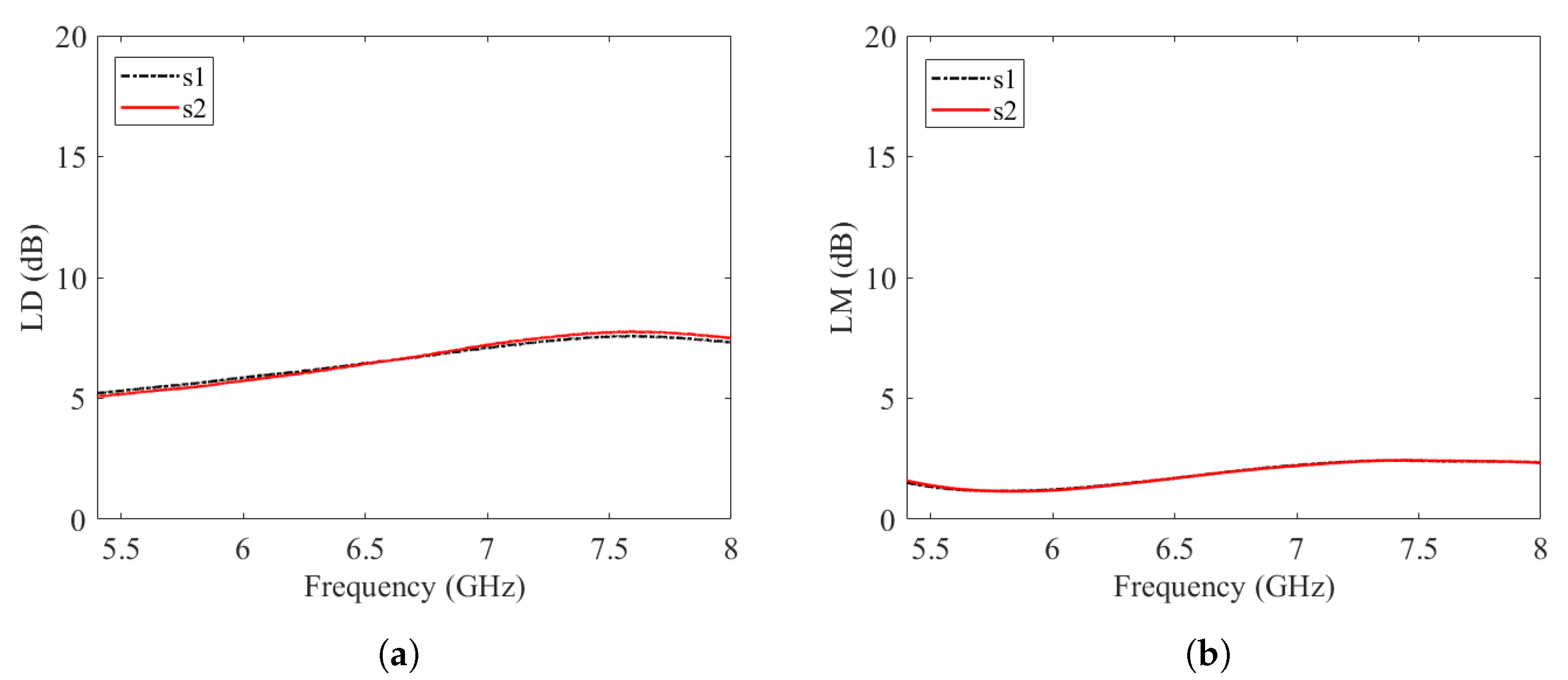
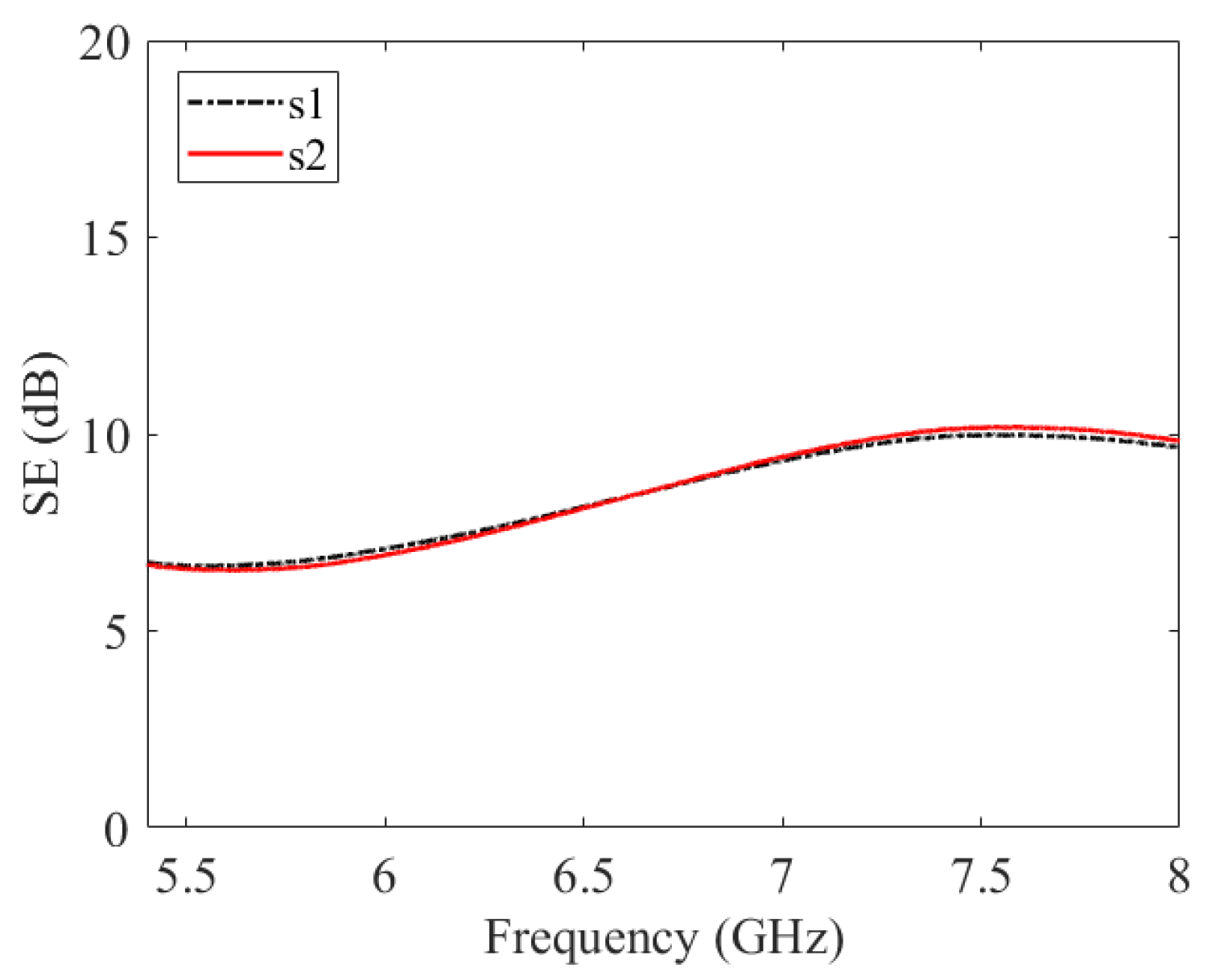
The dissipation losses ( L D ), the mismatch losses ( L M ), and the shielding effectiveness (SE) of the various samples are computed from the measurements of the scattering parameters using Equations (3), (5) and (6). The results for the cement-based composites without any filler (biochar or PVC) are shown in Figure 10a,b and Figure 11. The overlapped curves suggest a good reproducibility of results for the two samples. The SE increases from the value of 5 dB to 7 dB in the frequency band considered in the analysis.

3.3.1. Analysis with Different Concentration of Biochar

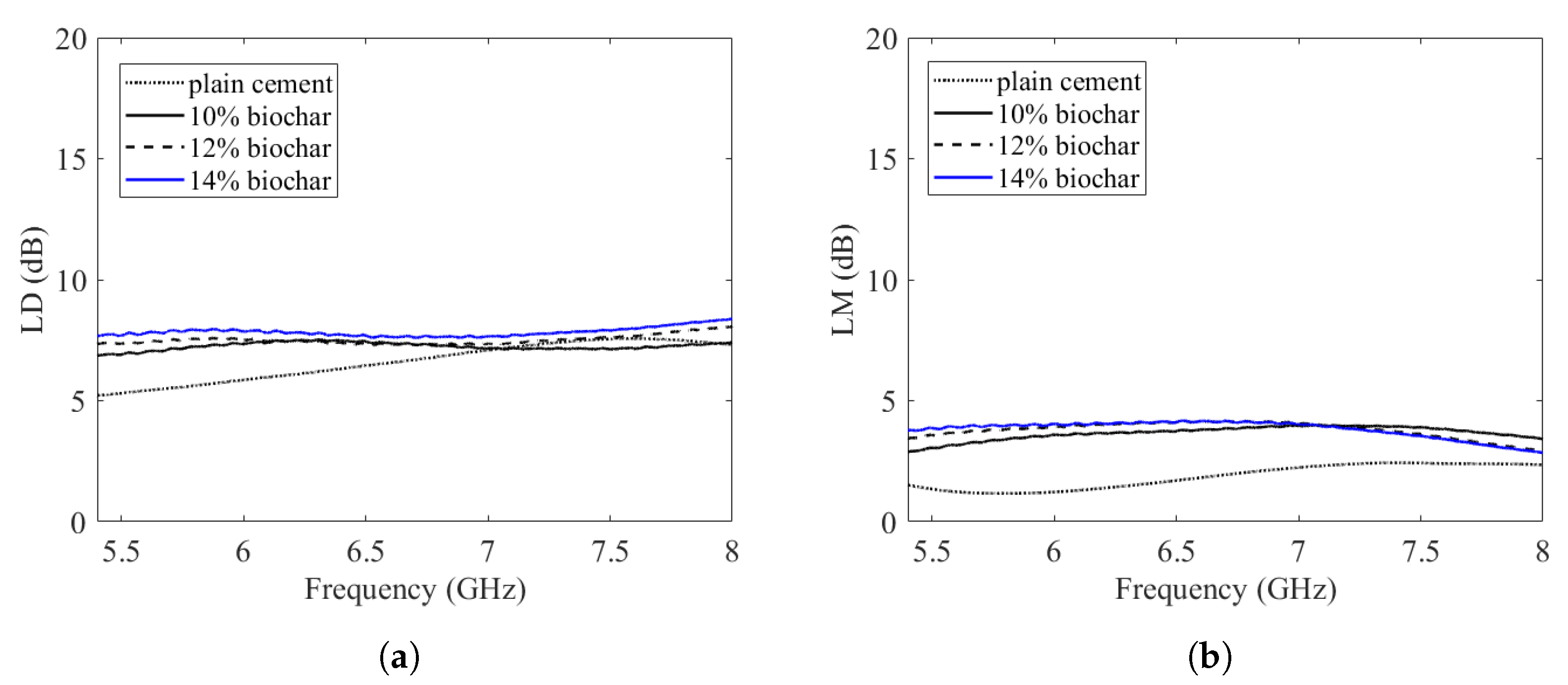
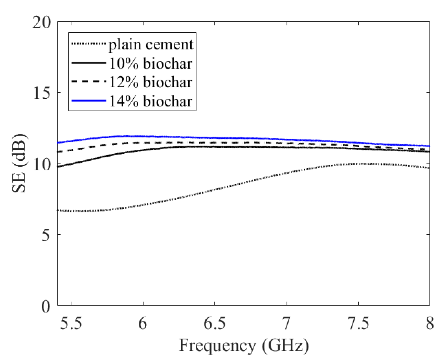
Samples with 5 % /c of PVC and different concentration of biochar ( 10 % /c, 12 % /c, 14 % /c) were realized. In the case of biochar with 12 % /c and 14 % /c, the resulting samples were slightly bigger than the cross-section of the waveguide and it was necessary to modify them in order to allow for a proper insertion in the waveguide spacer. Results of dissipation losses ( L D ), mismatch losses ( L M ), and shielding effectiveness (SE) are shown in Figure 12a,b and Figure 13.
There is not a great variation in the SE if the content of biochar is increased from 10 % /c to 14 % /c. For all cases, the SE does not change in the chosen frequency range.

3.3.2. Analysis of PVC Variation

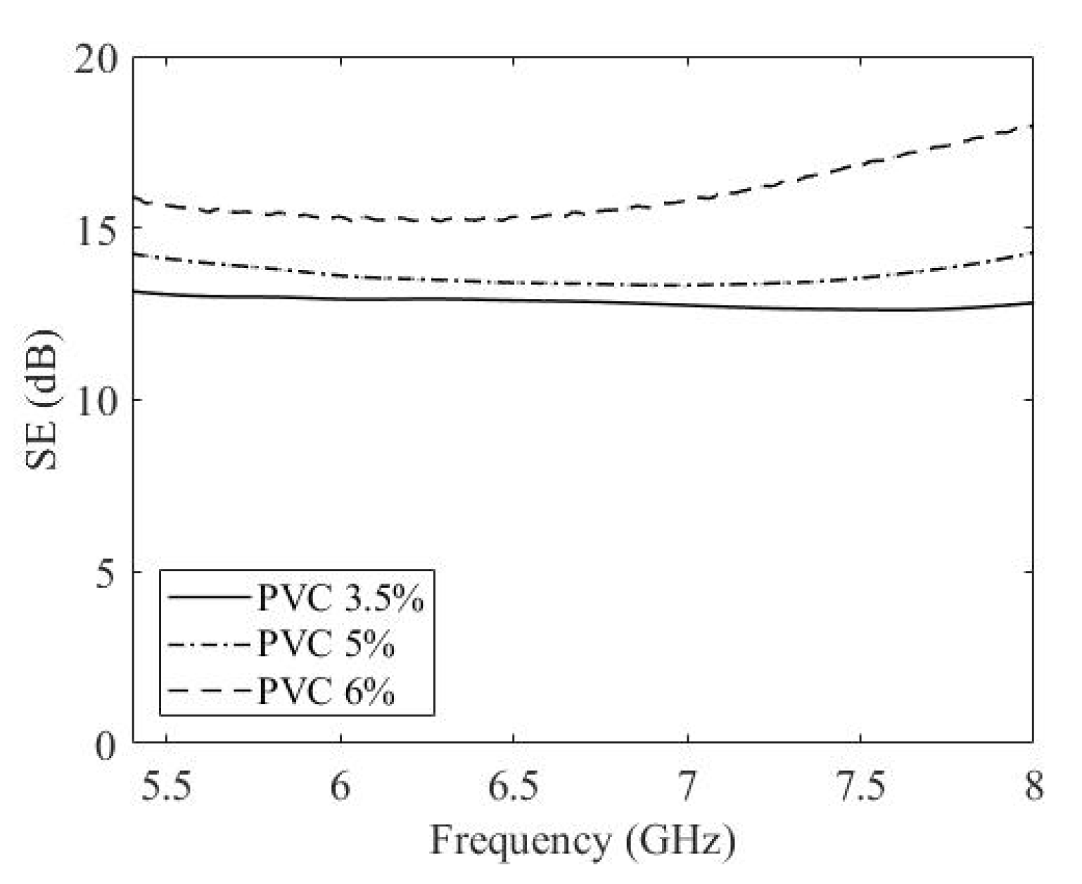
In the fabrication of cement-based composites with more than 6 % /c PVC, problems arise with the sample size. Due to the increase in the PVC content, the cement matrix is less compact, resulting in a limited shrinkage and consequent poor control of specimen geometry. For this reason, lower PVC weight fractions were considered ( 3.5 % /c, 5 % /c, and 6 % /c) with biochar filler 10 % /c. Results are shown in Figure 14. The sample with a 3.5 % /c content of PVC showed an SE of 13 dB, with a small variation in the considered frequency band. The average value of SE for samples with a 5 % /c content of PVC was around 14 dB. The average value of SE for samples with a 6 % /c content of PVC was around 16 dB. A larger variation in SE can be appreciated in the frequency band with respect to the case in which the PVC weight fraction was 6 % /c. By increasing the PVC percentage in the composites, the SE increases. Note that the samples analyzed are 4 mm thick and the SE can be further increased considering samples of larger thickness.
A combination of 10 wt.% biochar and 6 wt.% PVC provides the best shielding performance (around 16 dB).

4. Conclusions

This study investigated the addition of biochar and polyvinyl chloride (PVC) obtained from the sheathing of electrical cables to cement-based composites for electromagnetic shielding applications. The electronic waste from PVC cable outer casing can pose serious environmental and health risks if not properly treated. This analysis opens up a new perspective for PVC obtained from the sheathing of electrical cables which, instead of ending up in landfills, may even find a place in environmentally sustainable uses.
Several cement-based composites of thickness 4 mm with a fixed amount of PVC and a variable amount of biochar, or vice versa, were made. Optical imaging analysis reveals a proper matrix compactness and good distribution of the biochar and PVC into the matrix itself.
The shielding effectiveness of reference samples without any filler and samples with biochar and PVC was obtained from the scattering parameters measured in a rectangular waveguide in the C-band. No appreciable variation in the value of SE with respect to plain cement can be observed when keeping the PVC amount constant at 5 % /c and increasing the percentages of biochar from 10 % /c to 14 % /c. On the other hand, when the percentage of biochar is kept constant ( 10 % /c), increasing the amount of PVC results in an increase in the SE (from 13 dB to 16 dB). The higher values of SE with the increase in the amount of PVC is probably due to the presence of copper fragments in the PVC granules. In fact, since the PVC is obtained from old electric cables, traces of copper and other impurities are present in the mixture, as highlighted by X-ray diffraction analysis.
From the perspective of the circular economy, recycled PVC obtained from waste from previous processing can be fed back into new building materials. Moreover, it is possible to use PVC from processing waste to add it to a low-cost material such as biochar and obtain a viable solution for electromagnetic shielding in building construction.
This can be considered a preliminary study in the direction of creating a plaster mortar that is capable of shielding against electromagnetic fields. The material developed here does not yet fit into any of the commercially available categories. For use as a plaster mortar, it still requires one of the basic elements, namely sand. This will be the next step, even considering the fact that a plaster mortar has a thickness around 25 mm, well above the thickness of the samples studied here. This will mean that a higher shielding capacity can be achieved, the study of which will be the subject of future experiments.

Author Contributions

Conceptualization, P.S., I.N.S. and G.R.; methodology, P.S., I.N.S. and G.R.; validation, P.S.; formal analysis, P.S.; resources, P.S., I.N.S. and G.R.; data curation, P.S. and F.P.; writing—original draft preparation, P.S., I.N.S. and G.R.; writing—review and editing, P.S., I.N.S., G.R. and F.P.; visualization, P.S. and F.P.; supervision, P.S. and I.N.S. All authors have read and agreed to the published version of the manuscript.

Funding

This work was partially funded by Warrant Innovation Lab S.r.l.

Data Availability Statement

Data will be made available upon request.

Acknowledgments

Alessandro Sanginario is acknowledged for the realization of the molds with 3D printing, as well as Verónica Valentina Parra Pérez for the preparation of the specimens.

Conflicts of Interest

The authors declare no conflicts of interest.

References

  1. Aqeeli, M.; Leng, T.; Huang, X.; Chen, J.; Chang, K.; Alburaikan, A.; Hu, Z. Electromagnetic interference shielding based on highly flexible and conductive graphene laminate. Electron. Lett. 2015, 51, 1350–1352. [Google Scholar] [CrossRef]
  2. Jamshed, M.A.; Heliot, F.; Brown, T.W. A survey on electromagnetic risk assessment and evaluation mechanism for future wireless communication systems. IEEE J. Electromagn. RF Microw. Med. Biol. 2019, 4, 24–36. [Google Scholar] [CrossRef]
  3. Carlberg, M.; Koppel, T.; Hedendahl, L.K.; Hardell, L. Is the increasing incidence of thyroid cancer in the Nordic countries caused by use of mobile phones? Int. J. Environ. Res. Public Health 2020, 17, 9129. [Google Scholar] [CrossRef] [PubMed]
  4. Ravaioli, F.; Bacalini, M.G.; Giuliani, C.; Pellegrini, C.; D’Silva, C.; De Fanti, S.; Pirazzini, C.; Giorgi, G.; Del Re, B. Evaluation of DNA Methylation Profiles of LINE-1, Alu and Ribosomal DNA Repeats in Human Cell Lines Exposed to Radiofrequency Radiation. Int. J. Mol. Sci. 2023, 24, 9380. [Google Scholar] [CrossRef] [PubMed]
  5. Kim, J.H.; Lee, J.K.; Kim, H.G.; Kim, K.B.; Kim, H.R. Possible effects of radiofrequency electromagnetic field exposure on central nerve system. Biomol. Ther. 2019, 27, 265. [Google Scholar] [CrossRef] [PubMed]
  6. Banik, S.; Bandyopadhyay, S.; Ganguly, S. Bioeffects of microwave—A brief review. Bioresour. Technol. 2003, 87, 155–159. [Google Scholar] [CrossRef] [PubMed]
  7. Gupta, S.; Tai, N.H. Carbon materials and their composites for electromagnetic interference shielding effectiveness in X-band. Carbon 2019, 152, 159–187. [Google Scholar] [CrossRef]
  8. Savi, P.; Yasir, M.; Bartoli, M.; Giorcelli, M.; Longo, M. Electrical and microwave characterization of thermal annealed sewage sludge derived biochar composites. Appl. Sci. 2020, 10, 1334. [Google Scholar] [CrossRef]
  9. Savi, P.; Yasir, M.; Giorcelli, M.; Tagliaferro, A. The effect of carbon nanotubes concentration on complex permittivity of nanocomposites. Prog. Electromagn. Res. M 2017, 55, 203–209. [Google Scholar] [CrossRef]
  10. Khushnood, R.A.; Ahmad, S.; Savi, P.; Tulliani, J.M.; Giorcelli, M.; Ferro, G.A. Improvement in electromagnetic interference shielding effectiveness of cement composites using carbonaceous nano/micro inerts. Constr. Build. Mater. 2015, 85, 208–216. [Google Scholar] [CrossRef]
  11. Geetha, S.; Satheesh Kumar, K.; Rao, C.R.; Vijayan, M.; Trivedi, D. EMI shielding: Methods and materials—A review. J. Appl. Polym. Sci. 2009, 112, 2073–2086. [Google Scholar] [CrossRef]
  12. Zukowski, B.; dos Santos Mendonça, Y.G.; de Souza, J.V.B.; Filho, R.D.T. Chapter 20—Cement-based EMI shielding materials. In Materials for Potential EMI Shielding Applications; Joseph, K., Wilson, R., George, G., Eds.; Elsevier: Amsterdam, The Netherlands, 2020; pp. 333–340. [Google Scholar] [CrossRef]
  13. Chung, D. Materials for electromagnetic interference shielding. Mater. Chem. Phys. 2020, 255, 123587. [Google Scholar] [CrossRef]
  14. Manjunatha, M.; Vijaya Bhaskar Raju, K.; Sivapullaiah, P. Effect of PVC dust on the performance of cement concrete—A sustainable approach. In Recent Developments in Sustainable Infrastructure: Select Proceedings of ICRDSI 2019; Springer: Singapore, 2021; pp. 607–617. [Google Scholar]
  15. Akyıldız, A.; Durmaz, O. Investigating Electromagnetic Shielding Properties of Building Materials Doped with Carbon Nanomaterials. Buildings 2022, 12, 361. [Google Scholar] [CrossRef]
  16. Nam, I.; Kim, H.; Lee, H. Influence of silica fume additions on electromagnetic interference shielding effectiveness of multi-walled carbon nanotube/cement composites. Constr. Build. Mater. 2012, 30, 480–487. [Google Scholar] [CrossRef]
  17. Giorcelli, M.; Savi, P.; Delogu, A.; Miscuglio, M.; Yahya, Y.M.H.; Tagliaferro, A. Microwave absorption properties in epoxy resin Multi Walled Carbon Nanotubes composites. In Proceedings of the 2013 International Conference on Electromagnetics in Advanced Applications (ICEAA), Turin, Italy, 9–13 September 2013; pp. 1139–1141. [Google Scholar] [CrossRef]
  18. Liu, Z.; Ge, H.; Wu, J.; Chen, J. Enhanced electromagnetic interference shielding of carbon fiber/cement composites by adding ferroferric oxide nanoparticles. Constr. Build. Mater. 2017, 151, 575–581. [Google Scholar] [CrossRef]
  19. Aradoaei, M.; Ciobanu, R.C.; Schreiner, C.; Ursan, A.G.; Hitruc, E.G.; Aflori, M. Thermoplastic Electromagnetic Shielding Materials from the Integral Recycling of Waste from Electronic Equipment. Polymers 2023, 15, 3859. [Google Scholar] [CrossRef]
  20. Islam, T.; Safiuddin, M.; Roman, R.A.; Chakma, B.; Al Maroof, A. Mechanical Properties of PVC Fiber-Reinforced Concrete—Effects of Fiber Content and Length. Buildings 2023, 13, 2666. [Google Scholar] [CrossRef]
  21. Savi, P.; Cirielli, D.; di Summa, D.; Ruscica, G.; Sora, I.N. Analysis of shielding effectiveness of cement composites filled with pyrolyzed biochar. In Proceedings of the 2019 IEEE 5th International Forum on Research and Technology for Society and Industry (RTSI), Florence, Italy, 9–12 September 2019; pp. 376–379. [Google Scholar] [CrossRef]
  22. Yasir, M.; di Summa, D.; Ruscica, G.; Natali Sora, I.; Savi, P. Shielding properties of cement composites filled with commercial biochar. Electronics 2020, 9, 819. [Google Scholar] [CrossRef]
  23. di Summa, D.; Ruscica, G.; Savi, P.; Pelosato, R.; Natali Sora, I. Biochar-containing construction materials for electromagnetic shielding in the microwave frequency region: The importance of water content. Clean Technol. Environ. Policy 2023, 25, 1099–1108. [Google Scholar] [CrossRef]
  24. Giorcelli, M.; Savi, P.; Khan, A.; Tagliaferro, A. Analysis of biochar with different pyrolysis temperatures used as filler in epoxy resin composites. Biomass Bioenergy 2019, 122, 466–471. [Google Scholar] [CrossRef]
  25. Bennani, G.; Ndao, A.; Konan, D.; Brassard, P.; Roux, É.L.; Godbout, S.; Adjallé, K. Valorisation of Cranberry Residues through Pyrolysis and Membrane Filtration for the Production of Value-Added Agricultural Products. Energies 2023, 16, 7774. [Google Scholar] [CrossRef]
  26. Kurup, A.R.; Kumar, K.S. Novel fibrous concrete mixture made from recycled PVC fibers from electronic waste. J. Hazard. Toxic Radioact. Waste 2017, 21, 04016020. [Google Scholar] [CrossRef]
  27. Kurup, A.R.; Senthil Kumar, K. Effect of recycled PVC fibers from electronic waste and silica powder on shear strength of concrete. J. Hazard. Toxic Radioact. Waste 2017, 21, 06017001. [Google Scholar] [CrossRef]
  28. Pokorný, J.; Ševčík, R.; Zárybnická, L.; Podolka, L. The Role of High Carbon Additives on Physical–Mechanical Characteristics and Microstructure of Cement-Based Composites. Buildings 2023, 13, 1585. [Google Scholar] [CrossRef]
  29. Klapiszewski, Ł.; Klapiszewska, I.; Ślosarczyk, A.; Jesionowski, T. Lignin-based hybrid admixtures and their role in cement composite fabrication. Molecules 2019, 24, 3544. [Google Scholar] [CrossRef]
  30. Gupta, S.; Kua, H.W.; Dai Pang, S. Effect of biochar on mechanical and permeability properties of concrete exposed to elevated temperature. Constr. Build. Mater. 2020, 234, 117338. [Google Scholar] [CrossRef]
  31. Sirico, A.; Bernardi, P.; Sciancalepore, C.; Vecchi, F.; Malcevschi, A.; Belletti, B.; Milanese, D. Biochar from wood waste as additive for structural concrete. Constr. Build. Mater. 2021, 303, 124500. [Google Scholar] [CrossRef]
  32. Zhou, Z.; Wang, J.; Tan, K.; Chen, Y. Enhancing Biochar Impact on the Mechanical Properties of Cement-Based Mortar: An Optimization Study Using Response Surface Methodology for Particle Size and Content. Sustainability 2023, 15, 14787. [Google Scholar] [CrossRef]
  33. Suarez-Riera, D.; Falliano, D.; Carvajal, J.F.; Celi, A.C.B.; Ferro, G.A.; Tulliani, J.M.; Lavagna, L.; Restuccia, L. The Effect of Different Biochar on the Mechanical Properties of Cement-Pastes and Mortars. Buildings 2023, 13, 2900. [Google Scholar] [CrossRef]
  34. Ling, Y.; Wu, X.; Tan, K.; Zou, Z. Effect of Biochar Dosage and Fineness on the Mechanical Properties and Durability of Concrete. Materials 2023, 16, 2809. [Google Scholar] [CrossRef] [PubMed]
  35. Marcut, L.; Mohan, A.G.; Corneschi, I.; Grosu, E.; Paltanea, G.; Avram, I.; Badaluta, A.V.; Vasilievici, G.; Nicolae, C.A.; Ditu, L.M. Improving the Hydrophobicity of Plasticized Polyvinyl Chloride for Use in an Endotracheal Tube. Materials 2023, 16, 7089. [Google Scholar] [CrossRef] [PubMed]
  36. Siekierka, P.; Makarewicz, E.; Wilczewski, S.; Lewandowski, K.; Skórczewska, K.; Mirowski, J.; Osial, M. Composite of Poly(Vinyl Chloride) Plastisol and Wood Flour as a Potential Coating Material. Coatings 2023, 13, 1892. [Google Scholar] [CrossRef]
  37. Kocot, A. Impact of Artificial Waste on the Strength of Cementitious Composites. Multidiscip. Digit. Publ. Inst. Proc. 2019, 34, 11. [Google Scholar]
  38. Senhadji, Y.; Escadeillas, G.; Benosman, A.; Mouli, M.; Khelafi, H.; Ould Kaci, S. Effect of incorporating PVC waste as aggregate on the physical, mechanical, and chloride ion penetration behavior of concrete. J. Adhes. Sci. Technol. 2015, 29, 625–640. [Google Scholar] [CrossRef]
  39. Bolat, H.; Erkus, P. Use of polyvinyl chloride (PVC) powder and granules as aggregate replacement in concrete mixtures. Sci. Eng. Compos. Mater. 2016, 23, 209–216. [Google Scholar] [CrossRef]
  40. Merlo, A.; Lavagna, L.; Suarez-Riera, D.; Pavese, M. Mechanical properties of mortar containing waste plastic (PVC) as aggregate partial replacement. Case Stud. Constr. Mater. 2020, 13, e00467. [Google Scholar] [CrossRef]
  41. Valente, R.; De Ruijter, C.; Vlasveld, D.; Van Der Zwaag, S.; Groen, P. Setup for EMI shielding effectiveness tests of electrically conductive polymer composites at frequencies up to 3.0 GHz. IEEE Access 2017, 5, 16665–16675. [Google Scholar] [CrossRef]
  42. Rudd, M.; Baum, T.C.; Ghorbani, K. Determining high-frequency conductivity based on shielding effectiveness measurement using rectangular waveguides. IEEE Trans. Instrum. Meas. 2019, 69, 155–162. [Google Scholar] [CrossRef]
  43. Tamburrano, A.; Desideri, D.; Maschio, A.; Sarto, M.S. Coaxial waveguide methods for shielding effectiveness measurement of planar materials up to 18 GHz. IEEE Trans. Electromagn. Compat. 2014, 56, 1386–1395. [Google Scholar] [CrossRef]
  44. Jung, M.; Lee, Y.S.; Hong, S.G. Effect of incident area size on estimation of EMI shielding effectiveness for ultra-high performance concrete with carbon nanotubes. IEEE Access 2019, 7, 183105–183117. [Google Scholar] [CrossRef]
  45. Holloway, C.L.; Hill, D.A.; Ladbury, J.; Koepke, G.; Garzia, R. Shielding effectiveness measurements of materials using nested reverberation chambers. IEEE Trans. Electromagn. Compat. 2003, 45, 350–356. [Google Scholar] [CrossRef]
  46. Clayton, R.P. Shielding. In Introduction to Electromagnetic Compatibility; John Wiley & Sons, Ltd.: Hoboken, NJ, USA, 2005; pp. 713–752. [Google Scholar] [CrossRef]
  47. Narayanan, S.; Zhang, Y.; Aslani, F. Prediction Models of Shielding Effectiveness of Carbon Fibre Reinforced Cement-Based Composites against Electromagnetic Interference. Sensors 2023, 23, 2084. [Google Scholar] [CrossRef] [PubMed]
  48. Wohlfahrt, D.; Peller, H.F.M.; Müller, S.; Modler, N.; Mechtcherine, V. Investigation of helix-pultruded CFRP rebar geometry variants for carbon-reinforced concrete structures. Polymers 2023, 15, 3285. [Google Scholar] [CrossRef] [PubMed]
  49. Guan, H.; Liu, S.; Duan, Y.; Cheng, J. Cement based electromagnetic shielding and absorbing building materials. Cem. Concr. Compos. 2006, 28, 468–474. [Google Scholar] [CrossRef]
  50. Chung, D. Electromagnetic interference shielding effectiveness of carbon materials. Carbon 2001, 39, 279–285. [Google Scholar] [CrossRef]
  51. Singh, A.P.; Gupta, B.K.; Mishra, M.; Chandra, A.; Mathur, R.; Dhawan, S. Multiwalled carbon nanotube/cement composites with exceptional electromagnetic interference shielding properties. Carbon 2013, 56, 86–96. [Google Scholar] [CrossRef]
  52. Jiang, A.; Song, Z.; Wang, X.; Zhao, J.; Ren, J. Properties of Concrete Reinforced with a Basalt Fiber Microwave-Absorbing Shielding Layer. Sustainability 2023, 15, 15919. [Google Scholar] [CrossRef]
  53. Feng, L.; Xin, L.; Yuebo, L.; Zheng, P.; Jie, Y. Attenuation characteristics of high power microwave penetrating through reinforcement nets. High Power Laser Part. Beams 2012, 24, 2713–2717. [Google Scholar] [CrossRef]
  54. Lee, S.; Kim, G.; Kim, H.; Son, M.; Lee, Y.; Choi, Y.; Woo, J.; Nam, J. Electromagnetic Wave Shielding Properties of Amorphous Metallic Fiber-Reinforced High-Strength Concrete Using Waveguides. Materials 2021, 14, 7052. [Google Scholar] [CrossRef]
  55. Mann, K.S.; Rani, A.; Heer, M.S. Shielding behaviors of some polymer and plastic materials for gamma-rays. Radiat. Phys. Chem. 2015, 106, 247–254. [Google Scholar] [CrossRef]
  56. Mahmoud, K.; Lacomme, E.; Sayyed, M.; Özpolat, Ö.; Tashlykov, O. Investigation of the gamma ray shielding properties for polyvinyl chloride reinforced with chalcocite and hematite minerals. Heliyon 2020, 6, e03560. [Google Scholar] [CrossRef]
  57. Malkapur, S.M.; Ghodke, S.S.; Sujatha, P.; Singh, Y.; Shivakumar, K.; Sen, M.; Narasimhan, M.C.; Pulgur, A.V. Waste-polymer incorporated concrete mixes for neutron and gamma radiation shielding. Prog. Nucl. Energy 2021, 135, 103694. [Google Scholar] [CrossRef]
  58. Shakir, M.F.; Abdul Rashid, I.; Tariq, A.; Nawab, Y.; Afzal, A.; Nabeel, M.; Naseem, A.; Hamid, U. EMI shielding characteristics of electrically conductive polymer blends of PS/PANI in microwave and IR region. J. Electron. Mater. 2020, 49, 1660–1665. [Google Scholar] [CrossRef]
  59. Bhavsar, V.; Tripathi, D. Low and high frequency shielding effectiveness of PVC-PPy films. Polym. Bull. 2018, 75, 2085–2104. [Google Scholar] [CrossRef]
  60. Al-Ghamdi, A.A.; El-Tantawy, F. New electromagnetic wave shielding effectiveness at microwave frequency of polyvinyl chloride reinforced graphite/copper nanoparticles. Compos. Part A Appl. Sci. Manuf. 2010, 41, 1693–1701. [Google Scholar] [CrossRef]
  61. Matushko, I.P.; Noskov, Y.V.; Moiseienko, V.A.; Malyshev, V.Y.; Grishchenko, L.M. Electromagnetic Microwave Absorption Performances of PVC/AC Composites. Mater. Proc. 2023, 14, 15. [Google Scholar]
  62. ASTMC150-07; Standard Specification for Portland Cement. ASTM International: West Conshohocken, PA, USA, 2012. [CrossRef]
  63. Vassilev, S.V.; Baxter, D.; Andersen, L.K.; Vassileva, C.G. An overview of the chemical composition of biomass. Fuel 2010, 89, 913–933. [Google Scholar] [CrossRef]
  64. Savi, P.; Ruscica, G.; di Summa, D.; Natali Sora, I. Shielding Effectiveness Measurements of Drywall Panel Coated with Biochar Layers. Electronics 2022, 11, 2312. [Google Scholar] [CrossRef]
  65. Chen, L.; Zhou, T.; Yang, J.; Qi, J.; Zhang, L.; Liu, T.; Dai, S.; Zhao, Y.; Huang, Q.; Liu, Z.; et al. A review on the roles of biochar incorporated into cementitious materials: Mechanisms, application and perspectives. Constr. Build. Mater. 2023, 409, 134204. [Google Scholar] [CrossRef]
  66. Restuccia, L.; Ferro, G.A. Promising low cost carbon-based materials to improve strength and toughness in cement composites. Constr. Build. Mater. 2016, 126, 1034–1043. [Google Scholar] [CrossRef]
Figure 1. (a) Commercial biochar powder from wood pyrolysis. (b) PVC granules after sifting.
Carbon 10 00021 g001
Figure 2. Master and mold for sample preparation. Spacer for WR137 waveguide measurements. Samples of cement-based composites with no fillers.
Carbon 10 00021 g002
Figure 3. Dielectric slab of thickness d with an incident ( E i ) and transmitted ( E t ) electric field.
Carbon 10 00021 g003
Figure 4. Longitudinal view of the waveguide with the incident, reflected, and transmitted fields highlighted. The yellow rectangle represents the cement-based composite.
Carbon 10 00021 g004
Figure 5. Scattering parameter measurement setup. The sample to be measured is inserted between the two waveguides [21], inside the spacer (red circle).
Carbon 10 00021 g005
Figure 6. Observed intensities in the X-ray powder pattern of chopped PVC.
Carbon 10 00021 g006
Figure 7. Observed intensities in the X-ray powder pattern of cement-based composite with biochar 10 % /c and PVC 5 % /c after 14 days of aging.
Carbon 10 00021 g007
Figure 8. Fracture surface of a cement-based sample with no fillers.
Carbon 10 00021 g008
Figure 9. (a) Fracture surface of a cement-based sample with 10 % /c biochar and 5 % /c PVC. A PVC fragment is encircled by the red dashed line. The white arrow highlights a copper fragment, while the red arrows indicate some fragment of biochar. (b) A 100 μ m insight of a cement-based sample with 10%/c biochar and 5%/c PVC.
Carbon 10 00021 g009
Figure 10. (a) Dissipation losses ( L D ) and (b) mismatch losses ( L M ) of cement-based composites with no fillers.
Carbon 10 00021 g010
Figure 11. Shielding effectiveness of cement-based composites with no fillers.
Carbon 10 00021 g011
Figure 12. (a) Dissipation losses ( L D ) and (b) mismatch losses ( L M ) of cement-based composites with different biochar content and fixed PVC weight fraction ( 5 % /c).
Carbon 10 00021 g012
Figure 13. Shielding effectiveness of cement-based composites with different biochar content and fixed PVC weight fraction ( 5 % /c).
Carbon 10 00021 g013
Figure 14. Shielding effectiveness of cement-based composites with different PVC content and fixed biochar weight fraction (10%/c).
Carbon 10 00021 g014
Table 1. List of samples and their composition (weight percentage with respect to 50 g of cement).
SamplePVC %/cBiochar %/cWater %/cSuperplasticizer %/c
reference--351.5
constant PVC
B10-P5510531.8
B12-P5512571.8
B14-P5514611.8
constant biochar
B10-P3.53.510521.8
B10-P5510531.8
B10-P6610531.8
Table 2. List of samples and their composition (% mass/mass).
SampleCement
(% m/m)
PVC
(% m/m)
Biochar
(% m/m)
Water
(% m/m)
Superplasticizer
(% m/m)
reference73.30025.61.1
constant PVC
B10-P558.92.95.931.21.1
B12-P557.22.96.9321.0
B14-P5552.757.733.551
constant biochar
B10-P3.559.82.1631.11.1
B10-P558.92.95.931.21.1
B10-P658.53.55.931.01.1
Disclaimer/Publisher’s Note: The statements, opinions and data contained in all publications are solely those of the individual author(s) and contributor(s) and not of MDPI and/or the editor(s). MDPI and/or the editor(s) disclaim responsibility for any injury to people or property resulting from any ideas, methods, instructions or products referred to in the content.