Article

Fabrication of Magnetically Driven Microvalve Arrays Using a Photosensitive Composite

1
Department of Mechanical Engineering, Yamaguchi University, 2-16-1 Tokiwadai, Ube, Yamaguchi 755-8611, Japan
2
Department of Intelligent Mechanical Systems Engineering, Kagawa University, 2217-20 Hayashi-cho, Takamatsu, Kagawa 761-0396, Japan
3
Department of Micro Engineering, Kyoto University, Kyoto Daigaku-Katsura, Nishikyo-ku, Kyoto 615-8540, Japan
4
Division of Mechanical Science of Technology, Gunma University, 1-5-1 Tenjin-cho, Kiryu, Gunma 376-8515, Japan
5
JST, PRESTO, 4-1-8 Honcho, Kawaguchi, Saitama 332-0012, Japan
*
Author to whom correspondence should be addressed.
Magnetochemistry 2018, 4(1), 7; https://doi.org/10.3390/magnetochemistry4010007
Submission received: 30 November 2017 / Revised: 22 December 2017 / Accepted: 2 January 2018 / Published: 6 January 2018
(This article belongs to the Special Issue Magnetic Fields in Microfluidic Systems)

Abstract

:
Microvalves play an important role in fluid control in micro total analysis systems (µTAS). Previous studies have reported complex fabrication processes for making microvalve elements in a channel. Hence, there is a need for a simpler microvalve fabrication method for achieving throughput improvement and cost reduction in µTAS. In this study, we propose a simple fabrication method for a magnetically driven microvalve array using a photosensitive composite. The composite was prepared by mixing a photoresist and magnetic particles of pure iron. The simple fabrication process was performed by using a laminating layer composed of a sacrificial part and the composite in a channel. The microvalve elements were fabricated by one-step photolithography using the processability of the sacrificial layer and composite. Further, we demonstrated the magnetic driving property of the fabricated microvalve array device. Compared to devices containing non-driving microvalves, the flow rate was decreased by 50%, and the pressure difference between the inlet and outlet increased by up to 4 kPa with increase in driving microvalve elements. These results imply that our proposed device could be useful for practical µTAS applications.

1. Introduction

Micro total analysis systems (µTAS) have attracted attention owing to their feasibility as a tip-sized chemical testing and sample analysis device. Because µTAS are integrated with multiple microfluidic devices fabricated with micro electro mechanical system (MEMS) technology, they afford reductions in sample consumption, detection time, and device size. Therefore, µTAS are expected to be applied in point-of-care testing, where a chemical or biochemical test is performed and results are obtained immediately. Several microfluidic devices have been developed for the µTAS, such as micropumps [1,2], micromixers [3,4], and microvalves [5,6]. In particular, microvalves play an important role in fluid control and sample sorting in the µTAS.
Development of microvalves has been investigated extensively. There are two types of driving mechanisms for these microvalves. One is the mechanical driving mechanism, which controls the fluid using valve elements fabricated inside a channel structure [7,8,9]. For example, damming structures using thin-and-soft diaphragms or magnetically driven valve elements have been reported [10]. The other type is a chemical driving mechanism, which performs fluid control using a reversible microvalve controlled by a chemical reaction [11,12]. In the case of chemically driven microvalves, control methods using UV-sensitive materials or air bubbles have been developed [13,14]. Reports indicate that these microvalves show good fluid damming properties; however, they require multiple fabrication processes, such as photolithography, sputtering, and alignment, for assembly. Therefore, the overall productivity of the device is low, because of the long processing time. To achieve throughput improvement and reduction in the fabrication cost of µTAS, a fabrication method with fewer processing steps is in high demand.
To simplify the fabrication process, photosensitive composites with magnetic properties have been applied to produce mechanically driven devices [15,16,17,18,19]. The composite is prepared by mixing a photosensitive material and magnetic particles. Thus, the composite is magnetic, and can be processed by microfabrication. Because the composite enables the formation of microelements with driving properties by photolithography, applications in microactuators driven by non-contacting external magnetic fields have been reported. Damean et al. reported the fabrication of a cantilever-type micromirror using a composite of photoresist mixed with nickel particles [20]. Kandpal et al. demonstrated the actuation of a magnetic membrane fabricated using a composite prepared with photoresist and carbon-capped cobalt particles [21]. However, there are very few reports on the fabrication of microvalves using photosensitive composites [22]. There are no reports on the fabrication process for making multiple valve elements with a one-step lithography process.
In this study, we propose the fabrication of a microfluidic device with multiple microvalve elements processed by one-step photolithography using a photosensitive composite. To do this, we employed the processability of a sacrificial layer and a composite. A laminating layer composed of the sacrificial part and the composite in channel was utilized to realize a forming and releasing valve element with one-step photolithography. To achieve reproducibility of the fabrication process, we optimized the process conditions by evaluating the composite mixing method, thickness and development properties of the sacrificial layer, and the composite processability. Using this optimized fabrication process, we fabricated a microvalve array device with 100 serial-connected valve elements. Furthermore, we demonstrated the magnetic driving property of the microvalves in this device. The flow rate of the fluid flowing through the microvalves was controlled by a noncontact external magnetic field using a single magnet. We expect that this fabricated device and technique could be useful for application in µTAS.

2. Material and Methods

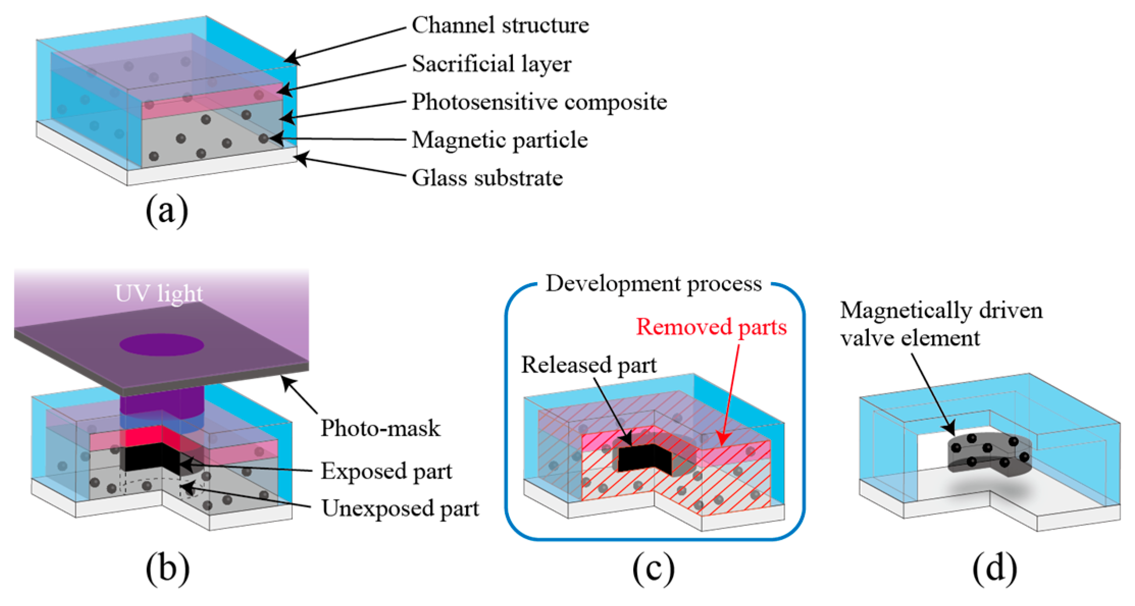
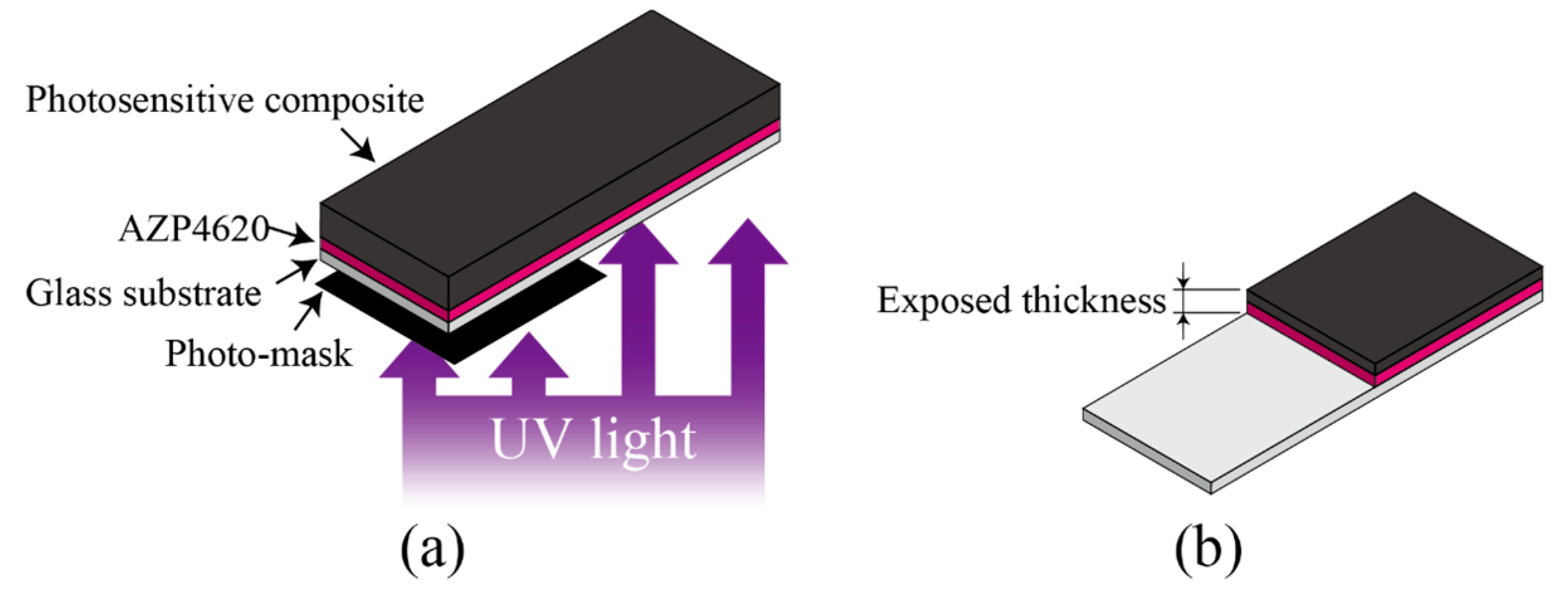
2.1. Principle of the Fabrication Process

We utilized the processability of the composite and sacrificial layer to produce the valve elements in a closed channel with one-step photolithography. Figure 1 shows a schematic diagram of the proposed fabrication process. The closed channel structure was formed on a glass substrate. The channel interior is filled with the sacrificial layer and the composite as the top and bottom layers, respectively (Figure 1a). The sacrificial layer plays a role of separation between channel wall and composite. The UV-exposed part of the composite forms a permanent structure with magnetic properties after the development process. UV is irradiated from the upper side of the channel structure to the composite thorough the sacrificial layer, channel wall, and photo-mask, which defines the shape of the microvalve element (Figure 1b). An unexposed part is formed beneath the exposed part, because the composite exhibits processability in UV lithography; the exposed area is thinner than usual for photoresist, because the dispersed magnetic particles decrease UV transmittance [23]. We remove the unexposed part and sacrificial layer, and simultaneously release the exposed part in a single development process (Figure 1c). The exposed part is formed as a microvalve element, which is manipulated arbitrarily in the channel structure using a magnetic field (Figure 1d). To achieve reproducibility of the fabrication process, the proposed method was optimized with respect to the process conditions, which include the composite mixing method, thickness and development properties of the sacrificial layer, and the composite processability.

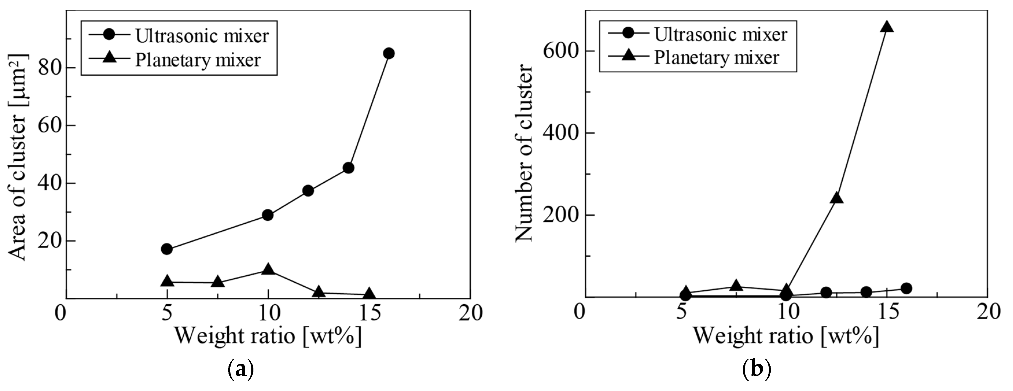
2.2. Mixing Method of Photosensitive Composite

The photosensitive composite used in our experiment was prepared by mixing a negative photoresist, SU-8 3010 (MicroChem, Westborough, MA, USA), and magnetic particles. Although there have been many reports on different types of magnetic particles [24,25], commercially available magnetic particles of pure iron with diameter 3–5 µm (FEE12PB, Kojundo Chemical Lab., Saitama, Japan) were used in this study. In the prepared composite, a large aggregation of the magnetic particles due to insufficient dispersion would result in the malformation of the composite, which would decrease the effectiveness of the driving property. Thus, a suitable mixing method that can sufficiently disperse the magnetic particles in SU-8 is required. To disperse the particles in SU-8, we mixed a surfactant (DISPERBYK-111, BYK, Wesel, Germany) with SU-8 in 2.5 wt % of mixing particles. Then, we compared two types of mixing methods to determine the most efficient mixing conditions. One method is to use ultrasonic cavitation generated by commercially available sonicator, and the other is a combination of rotation and revolution performed by a planetary mixer (KK-50S, Kurabo, Osaka, Japan). The mixing particles were weighed at 5–16 wt % of SU-8. After the mixing process of SU-8 and magnetic particles, the mixture was degassed for 10 min to remove bubbles from the composite. Finally, the prepared composite was coated on the glass substrate using a spin-coater. The dispersion of particles in the composites was evaluated by cluster area and cluster number in one-frame images using image processing software (Image J, NIH, Bethesda, MD, USA). Images were captured by a commercially available digital camera with transmitted light.

2.3. Optimization of Process Conditions

In our proposed fabrication process, because the sacrificial layer plays a role in the release of microvalve elements from the top-side channel structure, it is necessary to evaluate the sacrificial layer in terms of coating thickness and solubility in order to achieve reproducibility of the release process. Typically, thinner coatings and shorter solubility times in development of the sacrificial layer are more suitable for the release process, because these characteristics facilitate removal of the sacrificial layer. In this study, we used a positive-type photoresist, AZP4620 (AZ Electronic Materials, Luxembourg, Luxembourg) as the sacrificial layer. To control the coating thickness of the sacrificial layer, we modulated the viscosity of AZP4620 using a diluent and evaluated the relationship between the coating thickness and viscosity. The diluted AZP4620 was embedded on a concave structure of poly-dimethylpolysiloxane (PDMS; Silpot 184, Dow Corning Toray, Tokyo, Japan), which acts as a channel structure on the proposed device. Before and after the coating process, we measured the height of the concave structure using a surface roughness tester (SV-600, Mitsutoyo, Kanagawa, Japan), and calculated the coating thickness of the AZP4620 from the difference in height. To evaluate the solubility of the sacrificial layer, we examined the residue of AZP4620 with respect to soaking time in the developer. The fabrication process was modified from the conventional AZP4620 process by additional exposure and baking processes in order to use the same process as that of fabricating the valve elements. The AZP4620 was coated on the glass substrate to a thickness of 10 µm, and baked for 5 min at 110 °C. An additional process was performed for 10 min at 65 °C followed by 45 min at 95 °C. Then, the AZP4620/substrate structure was exposed to UV light (2 J/cm2 or 14 J/cm2), and subsequently baked for 5 min at 65 °C, followed by 7 min at 95 °C. We then used NMD-3 or SU-8 developers. The development times were 5, 10, 20, and 30 min. After the development process, we evaluated the residue of AZP4620 with respect to development time by measuring transmittance of the specimens using spectrophotometer (V-530, Jasco, Tokyo, Japan) at three photosensitive wavelengths for AZP4620: g-line (436 nm), h-line (405 nm), and i-line (365 nm).
In the fabrication process, using the composite processability, we have exposed and unexposed parts at the surface and within the structure, respectively. This processability is important for the simultaneous formation and release of the valve elements in the development process. Therefore, the exposed thickness of the composite should be lower than the height of the channel structure in order to release the valve elements from the bottom of the channel using under-etching of the unexposed parts. To evaluate the processability of the composite, we examined the change in exposed thickness with respect to the exposure dose. Figure 2 shows the evaluation method for the processability of the composite. We produced an exposed structure on a glass substrate by using the same fabrication process as for the valve elements, because measuring the exposed thickness in the channel structure was difficult. First, a sacrificial layer of AZP4620 was spin-coated on the substrate and baked for 5 min at 110 °C. Then, the composite was coated on the substrate at 60 µm, and underwent a prebake process, consisting of 5 min at 65 °C followed by 45 min at 95 °C. Half of the substrate was exposed by UV light from the back side of the coated surface, as shown in Figure 2a. The exposure doses were 3, 5, 8, and 12 J/cm2. After the exposure process, we performed a post-exposure bake (PEB) for 5 min at 65 °C followed by 7 min at 95 °C. In the development process, the unexposed parts were developed, and the exposed parts remained as a permanent structure (Figure 2b). We measured the thickness of exposed parts and evaluated the relationship between exposed thickness and exposure dose.

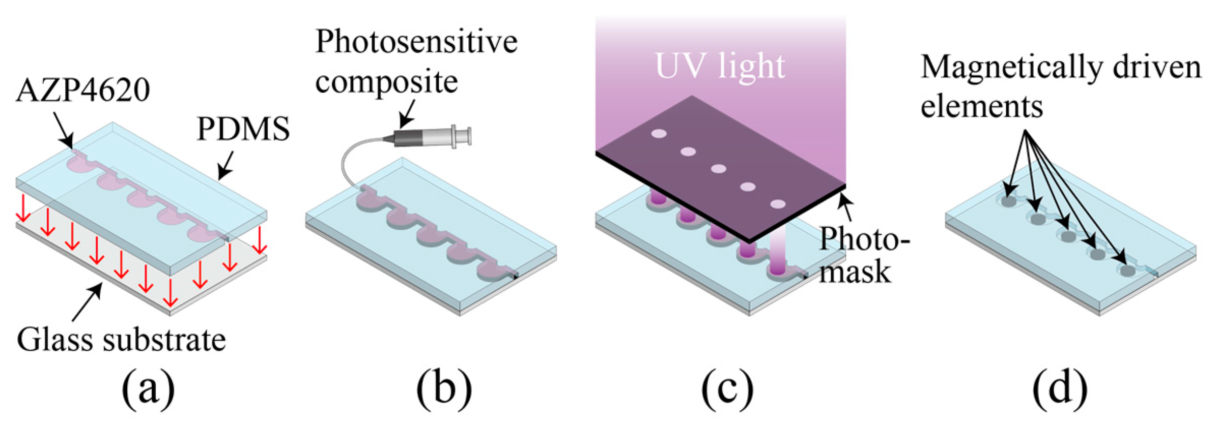
2.4. Fabrication Process of Microvalve Array Device

Our proposed fabrication process consists of making a closed channel, and introducing the composite into the channel; then, patterning the composite, followed by forming and releasing microvalves. Figure 3 shows a schematic diagram of our proposed fabrication process for making a microvalve array device. First, a concave channel structure was made by a conventional molding method using PDMS [26]. The channel structure was 300 µm in width, 100 µm in height, with φ1.5 mm × 100 chamber arrays. To make the sacrificial layer on the concave channel structure, AZP4620 diluted with a thinner (AZ5200 thinner, AZ Electronic Materials) was coated on the PDMS and baked for 60 min at 110 °C. Then, the PDMS was bonded with a glass substrate to make a closed channel (Figure 3a). We made an inlet and outlet at the ends of the channel structure, to which we connected a silicone tube. The prepared composite was introduced into the closed channel through the silicone tube using a syringe (Figure 3b). To cure the composite, a prebake process was performed for 5 min at 65 °C and 45 min at 95 °C. The valve shape of the composite was formed by UV exposure using a photo-mask, which defined the shape of the microvalve elements (Figure 3c). After the exposure process, PEB was performed for 5 min at 65 °C followed by 7 min at 95 °C to crosslink the exposed composite. Finally, the valve elements were formed and released by removing the unexposed parts and sacrificial layer using developer (Figure 3d). In the above processes, we adopted the optimal conditions, obtained as described in Section 2.2 and Section 2.3, for the composite preparation, coating thickness of AZP4620, exposure dose of composite, and forming and releasing conditions.

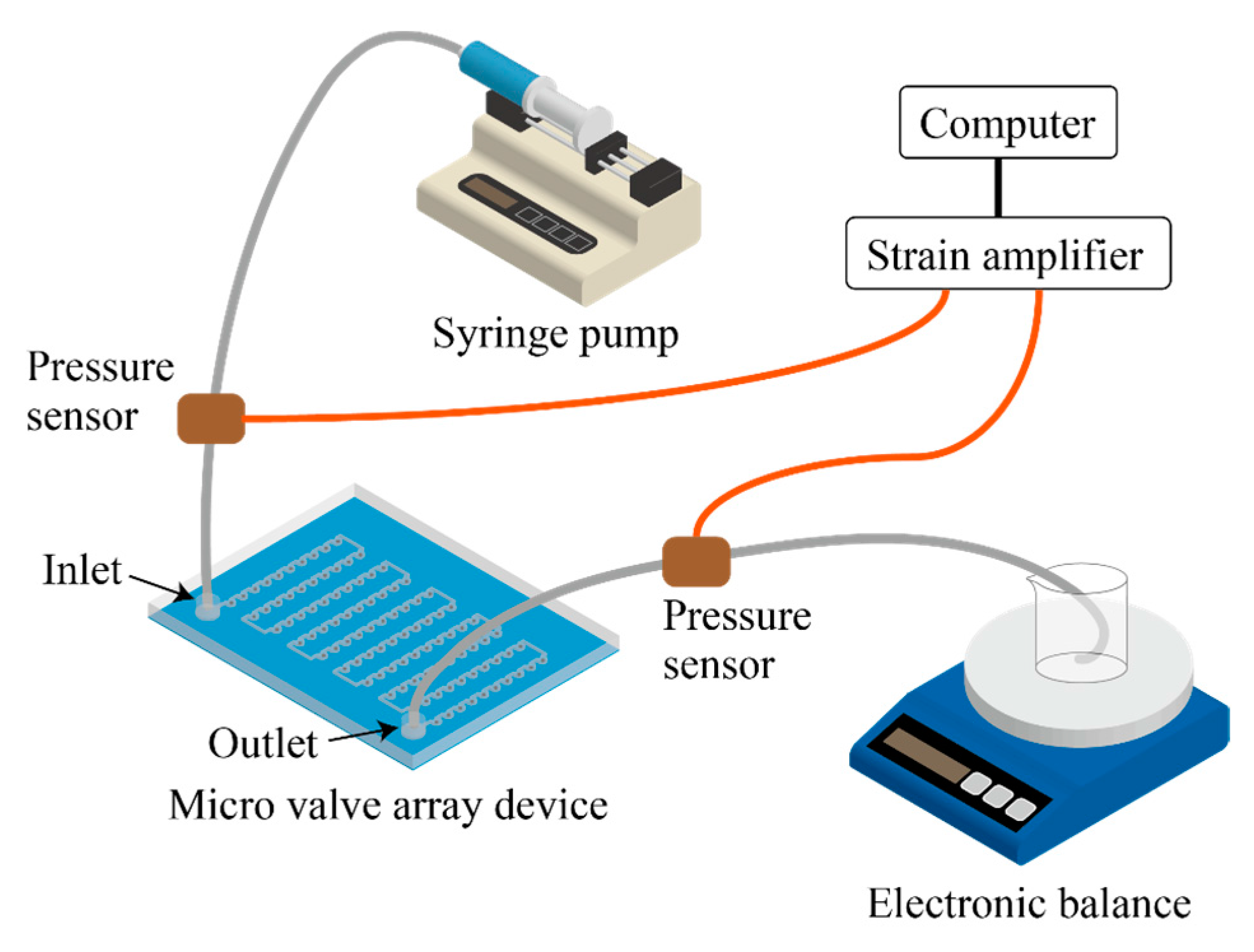
2.5. Evaluation Method of Microvalve Properties

To switch the open/close state, the proposed microvalves have a switching mechanism that is manipulated by a magnetic field. Figure 4 shows the schematic diagram of the driving mechanism of the microvalve elements. In the condition of flowing fluid in the channel, the microvalve elements are moved from the chamber to the channel structure following the flow direction, and provide flow resistance, which comprises the closed state of the valve (Figure 4a). On the contrary, microvalve elements are manipulated by a magnetic field to avoid the channel part. Then, the valve state is changed to open (Figure 4b). The proposed microvalve has a gap between the channel wall and the valve elements, because the sacrificial layer and unexposed parts have been removed. Therefore, one valve element exerts a low flow resistance. However, 100 serial-connected valve elements provide high flow resistance with good controllability by magnetic field manipulation.
To evaluate the performance of the valves in a microvalve array device, we performed an evaluation test using the setup shown in Figure 5. We perfused pure water from the inlet to the outlet using a syringe pump (KDS-270, KD Scientific, Holliston, MA, USA). Then, we measured the change in flow rate and pressure with manipulation of the valve switch. The weight of water from the outlet was measured by an electronic balance (AUW220D, Shimadzu, Kyoto, Japan). The flow rate was calculated as the measured weight of water per minute divided by concentration of water. The change in pressure with the manipulation of valves was evaluated by the difference in pressure, which was measured using pressure sensors (HV-100KPA-556, Showa Measuring Instruments, Tokyo, Japan) placed in the inlet and outlet. The manipulation of valves was performed by a commercially available neodymium magnet. We evaluated change in flow rate and pressure with respect to the number of valve elements.

3. Results and Discussion

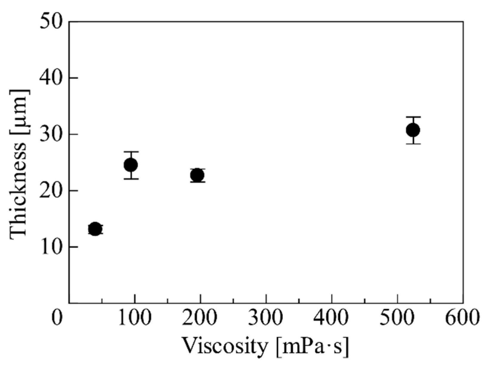
3.1. Characteristics of Photosensitive Composite

Figure 6 shows the evaluation results of particle dispersion in the composite, which was observed after mixing by ultrasonication or using a planetary mixer. Figure 6a shows the results of cluster area with respect to the change in weight ratio of magnetic particles. The evaluated cluster area was 5–10 µm2 under planetary mixing. The cluster area using ultrasonication increased with increasing particle weight ratio. These results indicate that the planetary mixing method yielded constant cluster area, regardless of the change in particle weight ratio. Figure 6b shows the results of cluster number with respect to the change in particle weight ratio. Although there is no difference in cluster number under ultrasonication, the cluster number increased with increasing particle weight ratio with the use of the planetary mixer. From these results, it can be seen that mixing by ultrasonication was not able to disperse the large aggregations in the same way as was possible with small aggregations, and thus the cluster number did not increase. In the case of the particle size and measurement method employed in this study, the particle dispersion was high under the conditions of small cluster area and large cluster number. The results evaluated above show that the planetary mixing method is effective for obtaining a composite with high dispersion. In addition, it is likely that ultrasonication is effective for dispersing small aggregations. Therefore, we used planetary mixing followed by ultrasonication to prepare the composite for the proposed microvalve array device.

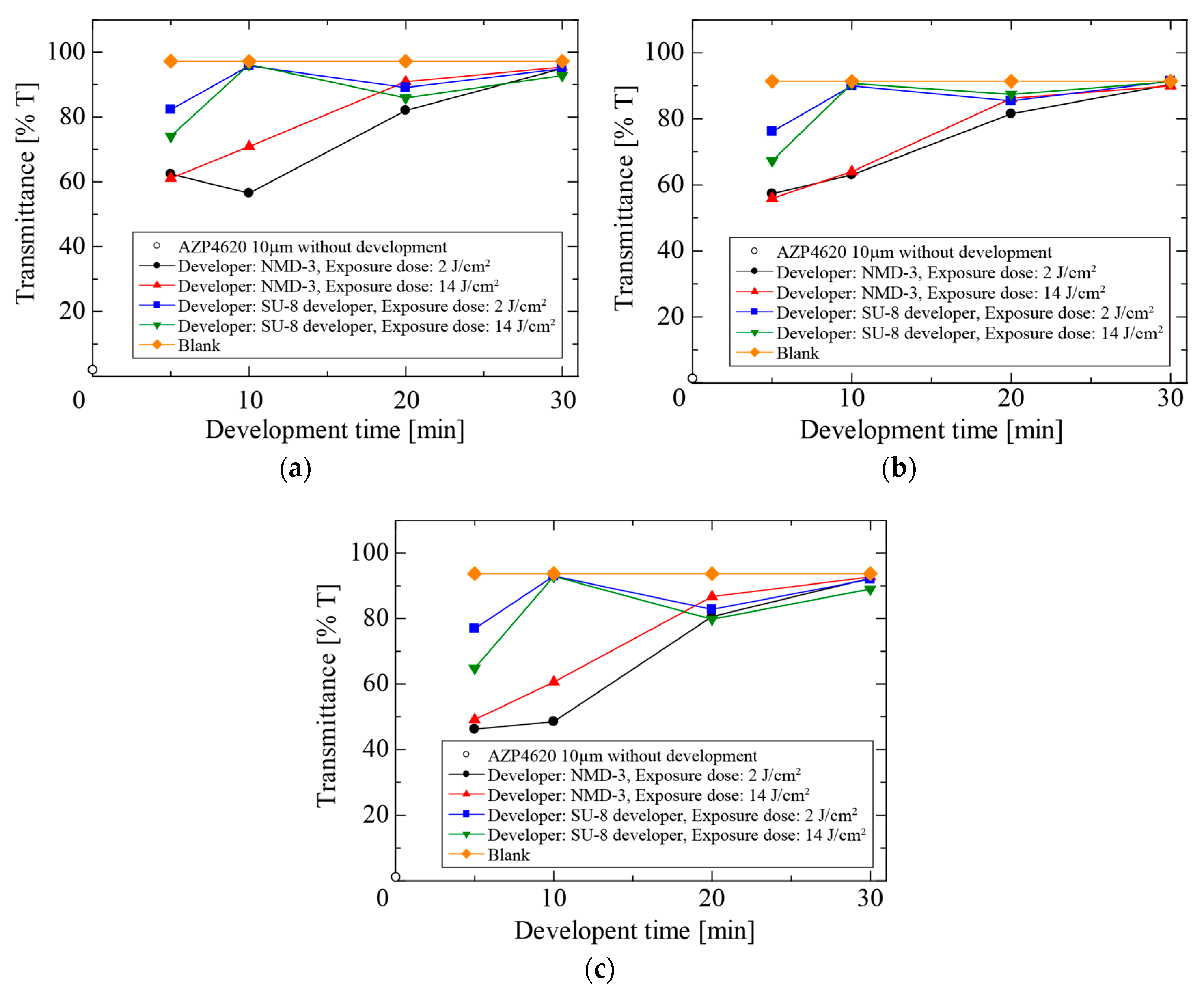
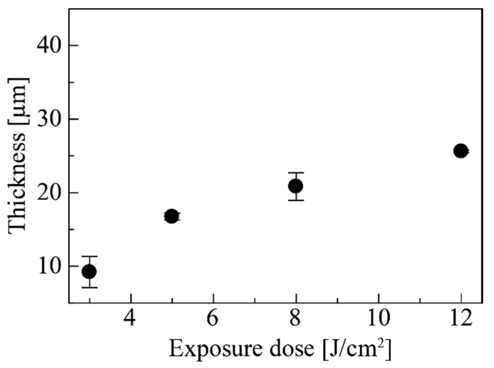
3.2. Evaluation of Process Condition

The thickness of the AZP4620 sacrificial layer increased with increasing viscosity, as shown in Figure 7. The evaluated results show that a maximum thickness of 30 µm and minimum thickness of 12 µm were obtained for viscosities of 500 mPa·s and 40 mPa·s, respectively. The reason for the change in thickness was the difference of volume of the thinner used with AZP4620. The volatilized thinner volume during the baking process determines the thickness of the cured AZP4620. These results indicate that the decrease in viscosity resulted in a decrease of the coating thickness. The viscosity adjustment enabled us to control the coating thickness of AZP4620 within a range of 12–40 µm.
Figure 8a–c shows the evaluation of measured transmittance with respect to changes in the development time of the AZP4620 residue after development. Although the transmittance was close to 0% at a thickness of 10 µm, the transmittance increased with increasing development time. The transmittance of AZP4620 was almost equivalent to the blank after 30 min of development, indicating that the AZP4620 coated on the substrate had largely been removed. There was no difference in the transmittance of AZP4620 between exposure doses of 2 mJ/cm2 and 14 mJ/cm2. The change in transmittance showed the same tendency for three photosensitive wavelengths: g-, h-, and i-line. In comparing the developers, the SU-8 developer reached high transmittance more quickly than the NMD-3 developer. Therefore, the SU-8 developer is effective for the rapid removal of AZP4620.
Figure 9 shows the measured results of composite thickness with changing exposure dose for the evaluation of the composite processability. The exposed thickness changed with the exposure dose, and showed a maximum thickness of 25 µm at 12 J/cm2. The approximate controllable range of exposed thickness was from 10 to 25 µm with an exposure dose range from 2 to 12 J/cm2. The exposed thickness was small for the low exposure dose of 3 J/cm2, because the composite was exposed by UV light through the AZP4620 sacrificial layer in addition to the decrease in transmittance due to the magnetic particles. However, because there is no change in exposed thickness for exposure doses over 8 J/cm2, a constant exposed thickness was obtained with reproducibility. This result is effective in the exposure process for the composite in channel. An unexposed part is formed beneath exposed part, and it is utilized to release the exposed part as microvalve element in the single development process.
The results of our evaluation indicate the following optimum conditions for the fabrication process of the proposed microvalve array device. The AZP4620 sacrificial layer thickness of 12 µm is effective for easily releasing the microvalve elements. The exposure dose for the composite should be set at 12 J/cm2 to achieve an exposed thickness of 25 µm. This exposed thickness presents the possibility to obtain good valve properties, because it yielded the highest occupied ratio of the valve in the channel. In the development process, the use of SU-8 developer will simultaneously remove the unexposed part of the composite and the AZP4620 sacrificial layer, and release the exposed part as the valve element.

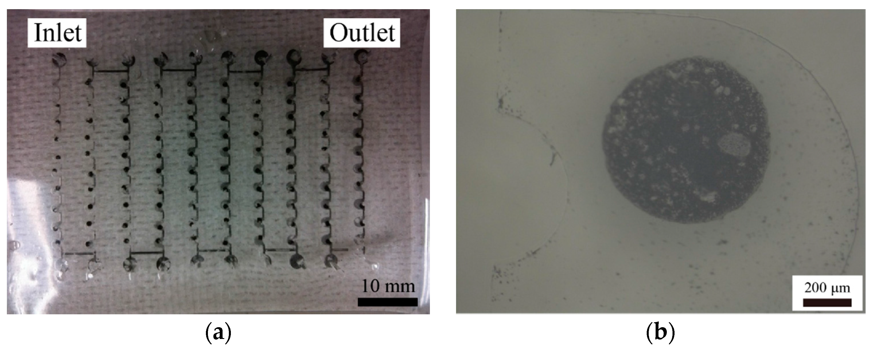
3.3. Fabrication Result of Microvalve Array Device

Figure 10a,b shows the whole image of the fabricated microvalve array device and an enlarged view of a microvalve element, respectively. The measured diameter of the fabricated valve element was approximately 700 µm, which represented a dimensional error of 17% compared to the designed value of 600 µm. Because there was a large gap between the composite and photo-mask due to the interposition of the PDMS channel structure and sacrificial layer, the dimensional error may have occurred due to UV diffraction induced by the gap. Moreover, it is possible that the fabricated pattern was larger than the designed value, because the exposure dose of 12 J/cm2 was 30 times higher than the conventional exposure dose of 0.4 J/cm2. The fabricated valve elements were released, and their driving properties by applied magnetic field were observed. These results demonstrate the fabrication of a magnetically driven microvalve array device using the proposed method. Our proposed method is obviously a short and simple fabrication process compared with previous methods, because there is no need for sputtering, plating, or assembly processes in forming magnetically driven elements.

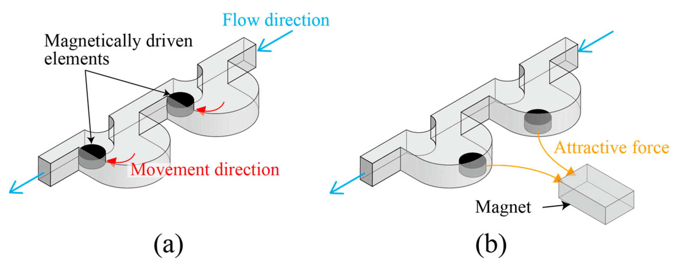
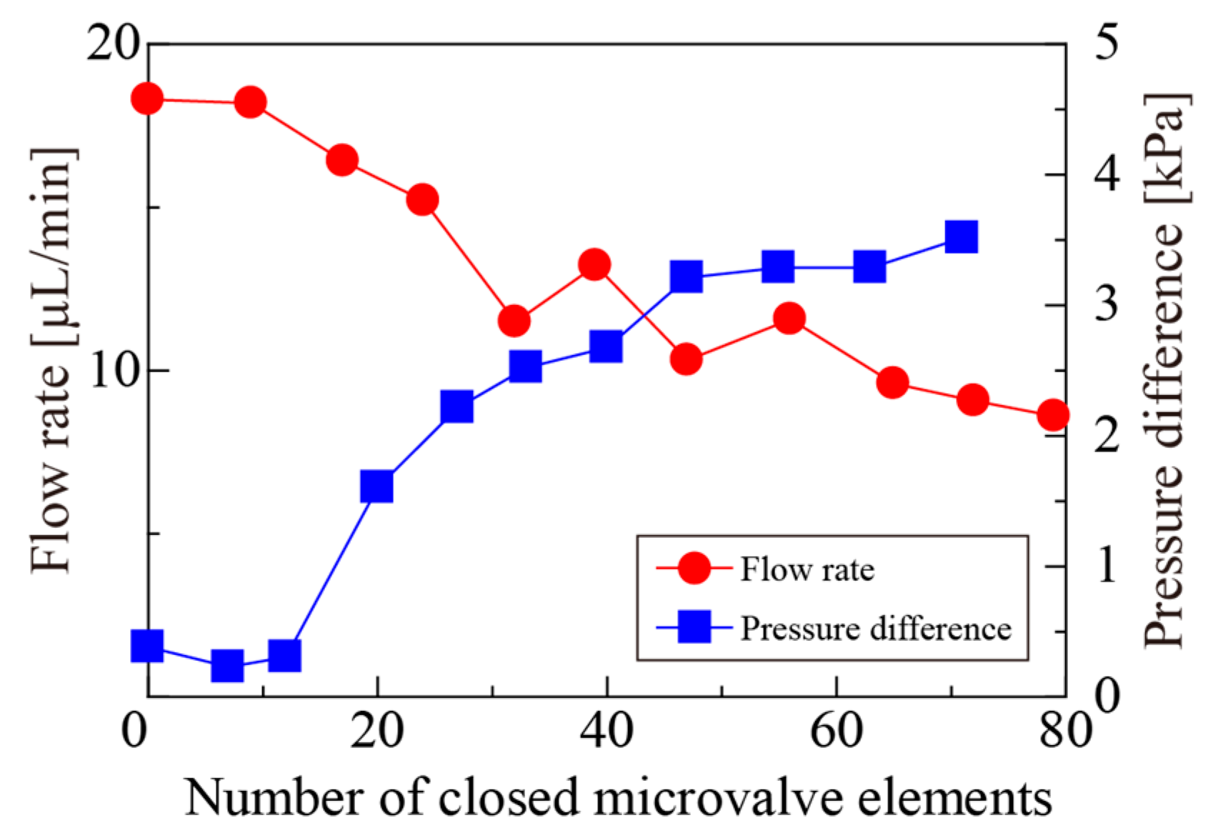
3.4. Valve Properties in Applied Magnetic Field

The evaluated valve properties of the fabricated microvalve array device are shown in Figure 11. The magnet was shifted in parallel with the substrate surface at the backside of fabricated device. Ten microvalve elements were formed in each line, and there are 10 lines on the device. The microvalve elements kept their position without being affected by flow field after magnetic manipulation, enabling the alteration of the position of the microvalves line-by-line. We measured the flow rate and pressure difference for change of number in closed microvalve elements using the above conditions. In the fabricated valve elements, we observed that 80- and 70-valve elements were driven in the measurement of flow rate and pressure difference, respectively. The non-functional valve elements were the result of an unsuccessful exposure process during valve element formation owing to the misalignment of the photomask. This could be improved by performing a modification process for the misalignment. In addition, the development efficiency is significantly decreased due to the difficulty of performing the development perfusion in the closed microchannel. Therefore, the development of microvalve elements in microchannels is difficult, and some of the microvalves might be not released due to the residue of the unexposed part. Moreover, the release of valve elements would be obstructed if a lack of sacrificial layer is yielded at the laminating layer, because the composite layer adheres to the channel wall. The decrease in the number of driving valve elements is due to their adhesion to the glass substrate over time after fabrication. There is no breakdown of microvalves due to a leakage of particles or water absorption. The fabricated microdevice could be used for a longer term by the incorporation of additional adhesion-prevention processes. We measured the decrease of the flow rate (red-filled circles) with increase in the number of the driving valve elements. In contrast, the pressure difference (blue squares) increased with an increase in the number of the driving valve elements. The minimum flow rate was approximately 50% compared to the initial value, and the maximum pressure difference was 4 kPa. The valve property for one valve element is calculated, and showed the flow rate and pressure difference were decrease of 0.6% and increase of 0.06 kPa, respectively. The proposed device demonstrated flow rate and pressure control using applied magnetic fields. In addition, the valve performance could be improved by increasing the number of valve elements.
For future work, there are practical issues, such as the reproducibility of fabrication, lifetime and dynamic response of microvalve elements. The reproducibility of fabrication could be improved by optimizing finely each fabrication process such as making process of laminating layer and development process with microchannel shape having lower flow resistance. In addition, it is necessary to evaluate the lifetime of microvalves according to applications because it could be affected by a usage environment. While we fabricated the magnetically driven microvalves using composites in closed channels and evaluated the quasi-static efficacy of fabricated microvalves, dynamic properties such as response speed of the microvalves under typical driving conditions have not yet been evaluated. Therefore, more detailed experimentation would be required to evaluate the dynamic properties of microvalve elements for practical applications.

4. Conclusions

In this study, we proposed a fabrication method for a microvalve array device using a photosensitive composite to perform a simple fabrication process for a microfluidic device. To ensure the reproducibility of the proposed fabrication method, we evaluated the composite mixing method, coating process, method of removal of the sacrificial layer, and the exposed thickness of the composite with respect to exposure dose. The microvalve array device, which has 100 serial-connected valve elements, was fabricated by one-step photolithography. We observed the driving property of valve elements manipulated by an applied magnetic field. For evaluating the valve properties, we used pure water at a constant flow rate into the channel structure and manipulated the valve elements using an applied magnetic field. The flow rate decreased by 50% compared to the initial value. The pressure difference between the inlet and outlet increased with an increase in the number of valve elements, and showed the maximum pressure of 4 kPa. Based on these results, we demonstrated that the proposed method is effective for the simplified fabrication of microfluidic devices. The insights obtained here could be useful for achieving high throughput and low fabrication cost in producing microvalves for application in µTAS.

Acknowledgments

This work was partly supported by JSPS KAKENHI Grant Number JP17H03196, JST PRESTO Grant Number JPMJPR15R3, and Center for Nano Lithography & Analysis, The University of Tokyo, supported by MEXT, Japan.

Author Contributions

J.S., Y.H. and T.S. conceived and designed the experiments; J.S. and Y.H. performed the experiments; T.N., J.S. and Y.H. analyzed the data; T.N., J.S., Y.H., F.S., H.K. and T.S. discussed and interpreted the results; T.N. and T.S. wrote the paper.

Conflicts of Interest

The authors declare no conflict of interest. The funding sponsors had no role in the design of the study; in the collection, analyses, or interpretation of data; in the writing of the manuscript, or in the decision to publish the results.

References

  1. Lee, C.J.; Sheen, H.J.; Tu, Z.K.; Lei, U.; Yang, C.Y. A study of PZT valveless micropump with asymmetric obstacles. Microsyst. Technol. 2009, 15, 993–1000. [Google Scholar] [CrossRef]
  2. Yang, K.-S.; Chao, T.-F.; Chen, I.Y.; Wang, C.-C.; Shyu, J.-C. A comparative study of nozzle/diffuser micropumps with novel valves. Molecules 2012, 17, 2178–2187. [Google Scholar] [CrossRef] [PubMed]
  3. Nguyen, N.T.; Wu, Z. Micromixers—A review. J. Micromech. Microeng. 2005, 15, R1–R16. [Google Scholar] [CrossRef]
  4. Yang, S.Y.; Lin, J.L.; Lee, G.B. A vortex-type micromixer utilizing pneumatically driven membranes. J. Micromech. Microeng. 2009, 19, 035020. [Google Scholar] [CrossRef]
  5. Au, A.K.; Lai, H.; Utela, B.R.; Folch, A. Microvalves and micropumps for BioMEMS. Micromachines 2011, 2, 179–220. [Google Scholar] [CrossRef]
  6. Oh, K.W.; Ahn, C.H. A review of microvalves. J. Micromech. Microeng. 2006, 16, R13–R39. [Google Scholar] [CrossRef]
  7. Casals-Terré, J.; Duch, M.; Plaza, J.A.; Esteve, J.; Pérez-Castillejos, R.; Vallés, E.; Gómez, E. Design, fabrication and characterization of an externally actuated on/off microvalve. Sens. Actuators A Phys. 2008, 147, 600–606. [Google Scholar] [CrossRef]
  8. Groen, M.S.; Brouwer, D.M.; Wiegerink, R.J.; Lötters, J.C. Design considerations for a micromachined proportional control valve. Micromachines 2012, 3, 396–412. [Google Scholar] [CrossRef]
  9. Gholizadeh, A.; Javanmard, M. Magnetically actuated microfluidic transistors: Miniaturized micro-valves using magnetorheological fluids integrated with elastomeric membranes. J. Microelectromech. Syst. 2016, 25, 922–928. [Google Scholar] [CrossRef]
  10. Harper, J.C.; Andrews, J.M.; Ben, C.; Hunt, A.C.; Murton, J.K.; Carson, B.D.; Bachand, G.D.; Lovchik, J.A.; Arndt, W.D.; Finley, M.R.; et al. Magnetic-adhesive based valves for microfluidic devices used in low-resource settings. Lab Chip 2016, 16, 4142–4151. [Google Scholar] [CrossRef] [PubMed]
  11. Lee, D.E.; Soper, S.; Wang, W. Design and fabrication of an electrochemically actuated microvalve. Microsyst. Technol. 2008, 14, 1751–1756. [Google Scholar] [CrossRef]
  12. Ezkerra, A.; Fernández, L.J.; Mayora, K.; Ruano-López, J.M. A microvalve for lab-on-a-chip applications based on electrochemically actuated SU8 cantilevers. Sens. Actuators B Chem. 2011, 155, 505–511. [Google Scholar] [CrossRef]
  13. Demir, A.G.; Previtali, B.; Bestetti, M. Microvalve actuation with wettability conversion through darkness/UV application. J. Micromech. Microeng. 2011, 21, 025019. [Google Scholar] [CrossRef]
  14. Huang, C.; Tsou, C. The implementation of a thermal bubble actuated microfluidic chip with microvalve, micropump and micromixer. Sens. Actuators A Phys. 2014, 210, 147–156. [Google Scholar] [CrossRef]
  15. Suter, M.; Ergeneman, O.; Zürcher, J.; Moitzi, C.; Pané, S.; Rudin, T.; Pratsinis, S.E.; Nelson, B.J.; Hierold, C. A photopatternable superparamagnetic nanocomposite: Material characterization and fabrication of microstructures. Sens. Actuators B Chem. 2011, 156, 433–443. [Google Scholar] [CrossRef]
  16. Suter, M.; Ergeneman, O.; Zürcher, J.; Schmid, S.; Camenzind, A.; Nelson, B.J.; Hierold, C. Superparamagnetic photocurable nanocomposite for the fabrication of microcantilevers. J. Micromech. Microeng. 2011, 21, 025023. [Google Scholar] [CrossRef]
  17. Suter, M.; Zhang, L.; Siringil, E.C.; Peters, C.; Luehmann, T.; Ergeneman, O.; Peyer, K.E.; Nelson, B.J.; Hierold, C. Superparamagnetic microrobots: Fabrication by two-photon polymerization and biocompatibility. Biomed. Microdevices 2013, 15, 997–1003. [Google Scholar] [CrossRef] [PubMed]
  18. Li, H.; Flynn, T.J.; Nation, J.C.; Kershaw, J.; Scott Stephens, L.; Trinkle, C.A. Photopatternable NdFeB polymer micromagnets for microfluidics and microrobotics applications. J. Micromech. Microeng. 2013, 23, 065002. [Google Scholar] [CrossRef]
  19. Suzuki, J.; Onishi, Y.; Terao, K.; Takao, H.; Shimokawa, F.; Oohira, F.; Miyagawa, H.; Namazu, T.; Suzuki, T. Development of a two-dimensional scanning micro-mirror utilizing magnetic polymer composite. Jpn. J. Appl. Phys. 2016, 55, 06GP01. [Google Scholar] [CrossRef]
  20. Damean, N.; Parviz, B.A.; Lee, J.N.; Odom, T.; Whitesides, G.M. Composite ferromagnetic photoresist for the fabrication of microelectromechanical systems. J. Micromech. Microeng. 2005, 15, 29–34. [Google Scholar] [CrossRef]
  21. Kandpal, M.; Sharan, C.; Palaparthy, V.; Tiwary, N.; Poddar, P.; Rao, V.R. Spin-coatable, photopatternable magnetic nanocomposite thin films for mems device applications. RSC Adv. 2015, 5, 85741–85747. [Google Scholar] [CrossRef]
  22. Suzuki, T.; Suzuki, J.; Terao, K.; Takao, H.; Shimokawa, F.; Oohira, F.; Miyagawa, H. Development of magnetically driven microvalve using photosensitive SU-8/Fe composite. Int. J. Appl. Electrom. 2016, 52, 1585–1590. [Google Scholar] [CrossRef]
  23. Nakahara, T.; Hosokawa, Y.; Terao, K.; Takao, H.; Shimokawa, F.; Oohira, F.; Namazu, T.; Kotera, H.; Suzuki, T. Self-aligned fabrication process for active membrane made of photosensitive nanocomposite. In Proceedings of the Technical digest of 25th IEEE International Conference on Micro Electro Mechanical Systems, Paris, France, 29 January–2 February 2012; pp. 1181–1184. [Google Scholar]
  24. Nayek, C.; Manna, K.; Bhattacharjee, G.; Murugavel, P.; Obaidat, I. Investigating size- and temperature-dependent coercivity and saturation magnetization in PEG coated Fe3O4 nanoparticles. Magnetochemistry 2017, 3, 19. [Google Scholar] [CrossRef]
  25. Moulet, L.; Daro, N.; Etrillard, C.; Létard, J.F.; Grosjean, A.; Guionneau, P. Rational control spin-crossover particle size: From nano- to micro-rods of [Fe(Htrz)2(trz)] (BF4). Magnetochemistry 2016, 2, 10. [Google Scholar] [CrossRef]
  26. Friend, J.; Yeo, L. Fabrication of microfluidic devices using polydimethylsiloxane. Biomicrofluidics 2010, 4, 026502. [Google Scholar] [CrossRef] [PubMed]
Figure 1. Principle diagram of proposed fabrication process: (a) making process of laminating layer in closed channel; (b) UV exposure process; (c) development process; (d) after development process.
Magnetochemistry 04 00007 g001
Figure 2. Evaluation method for exposure thickness of composite. Schematic diagrams for (a) exposure process and (b) after development process.
Magnetochemistry 04 00007 g002
Figure 3. Schematic diagrams of proposed fabrication process: (a) Making closed channel; (b) introducing composite into channel; (c) patterning of composite; and (d) forming and releasing microvalves.
Magnetochemistry 04 00007 g003
Figure 4. Driving method of microvalve array device at (a) close and (b) open state.
Magnetochemistry 04 00007 g004
Figure 5. Setup for evaluation of valve properties.
Magnetochemistry 04 00007 g005
Figure 6. Evaluation of diffusion of magnetic particles in photosensitive composite: (a) Cluster area, and (b) number of clusters with respect to the change in weight ratio of magnetic particles.
Magnetochemistry 04 00007 g006
Figure 7. Thickness of baked AZP4620 with respect to change in viscosity.
Magnetochemistry 04 00007 g007
Figure 8. Transmittance vs. development time at (a) g-; (b) h-; and (c) i-line.
Magnetochemistry 04 00007 g008
Figure 9. Change in exposed thickness of composite.
Magnetochemistry 04 00007 g009
Figure 10. Observation of the fabricated microvalve array device in (a) whole view of the device and (b) enlarged view of microvalve element.
Magnetochemistry 04 00007 g010
Figure 11. Evaluation results of valve properties.
Magnetochemistry 04 00007 g011

