Continuous Anode Slurry Production in Twin-Screw Extruders: Effects of the Process Setup on the Dispersion


Institute of Mechanical Process Engineering and Mechanics, Karlsruhe Institute of Technology, Straße am Forum 8, 76131 Karlsruhe, Germany
*
Author to whom correspondence should be addressed.
Batteries 2024, 10(5), 145; https://doi.org/10.3390/batteries10050145
Submission received: 29 February 2024
/
Revised: 8 April 2024
/
Accepted: 16 April 2024
/
Published: 24 April 2024
(This article belongs to the Section Battery Processing, Manufacturing and Recycling)
Abstract
:Screw design in the extrusion process has an important effect on the distribution of material through the extruder, resulting in partially filled sections in the processing zone. Accordingly, the local accumulation of material in the extruder leads to variations in material strain conditions and also influences the local residence time of the material in a given screw section. This work evaluates particle dispersion in anode slurry considering three different screw arrangements. The particle size distribution is considered as a quality parameter representing the microstructure of the battery slurry components and their distribution. Numerical simulation of the material flow behavior through a laboratory extruder was performed to investigate the filling ratios and resulting shear rates for different screw designs and process conditions. The importance of process parameters and a suitable screw configuration to achieve specific particle sizes in battery slurry is discussed.
1. Introduction
The mixing process in battery cell production has a major impact on the performance of the battery as it affects the microstructure in the cells by changing the particle size distribution and dispersion of the electrode components. It also has a major impact on the rheological properties of the electrode pastes, thus affecting the processability of the materials in downstream production steps [1,2,3,4,5,6,7,8]. The mixing step can be performed in either batch or continuous operation depending on the production scale. The continuous process has several advantages over the batch process, mainly because it allows flexibility in both production rates and processing conditions, while at the same time, it allows a reduction in quality fluctuations [1,2]. The integration of a twin-screw extruder as a suitable continuous mixing device in the battery production process has been addressed by various researchers and is widely used in the industry [1,2,9]. Further, extrusion of battery slurries compared to other mixing techniques has shown promising advantages in terms of flexibility, reducing operating costs, and the ability to process slurries with low solvent content [2].
Due to its versatility, the extrusion process can be implemented using different strategies for both anode and cathode slurry production. Here, the process parameters and screw design play an important role in achieving specific product qualities. At the cathode side, Haarmann et al. [9] investigated the effects of different process conditions in an extruder on the rheological properties and particle sizes of NMC622 or Li(Ni0.6Mn0.2Co0.2)O2 slurries. Here, the effects of a solid or wet binder dosing (PVDF or polyvinylidene fluoride) on the continuous mixing step was discussed. Moreover, Haarmann et al. compared two screw configurations with differences in the kneading sections. Although there were no major changes in the viscosity, an effect of screw configuration on particle dispersion was observed. By using wider kneading elements, better dispersion and particle breakage were achieved, especially when using dry binders. Similarly, the significance of the screw configuration was also recently addressed by Wiegmann et al. [10] for anodes. The study investigated the extrusion of graphite anode pastes with low solvent content and evaluated different screw configurations. The implemented screw designs targeted different specific power inputs and showed a crucial effect on the electrode properties, especially on the resulting internal surface area of the anodes, which caused variations in cell capacity.
Since twin-screw extruders generally have closed construction, the evaluation of the mixing efficiency in the process can only be achieved through measurements of the product quality. However, this usually requires long development time and expertise. Therefore, understanding the material flow behavior in the process in relation to different process conditions is of great interest, especially in order to optimize the process for novel and existing battery materials. While experimental analyses can be extensive, process simulations provide a method to support process development and to understand product changes during production.
For the mixing step, depending on the simulation scale to be analyzed, extruders are usually difficult to model due to their geometry and complex design [11]. Different authors have modeled twin-screw extruders based on dimensionless numbers in order to calculate the flow behavior according to empirical correlations for different process configurations [11,12]. This approach has great advantages as it allows the approximation of process information such as filling ratios, pressure gradients and drive power across the extruder screw using simple equations, especially when compared to more complex flow simulations of the entire extruder screw, which provide more detailed information about the process but require more computation. Eitzlmayr et al. [12] presented a model for pharmaceutical hot-melt extrusion (HME) based on empirical parameters, which were obtained through process simulation, and they further discussed the incorporation of the polymer melt rheology. Later, Eitzlmayr et al. [13] introduced a 3D flow simulation framework based on the smoothed particle hydrodynamics (SPH) method to obtain further process information based on single screw elements. Similarly, Lewandowski et al. [14] investigated the pumping efficiency of individual elements for hot-melt extrusion and used 3D FEM simulation to obtain screw coefficients to calculate material flow in the extruder. The simulation was conducted using Polyflow v.15.0 (ANSYS) and then validated experimentally. Both approaches rely on the simulation of individual screw elements that are coupled for larger zone simulations. Moreover, a simulation-based study of the extrusion of battery material using a conical extruder was presented by Paredes-Goyes et al. [15] for solvent-free applications based on the DEM method. It provided an approach to evaluate the particle orientation for different cohesion forces and screw speeds to obtain different representative microstructures. Ellwanger et al. [16] investigated both the local residence time and the thermomechanical stress for protein extrusion using flow simulations based on the moving particle semi-implicit (MPS) method. Thereby, the effects of three standard kneader sections were discussed and then compared against experiments. The results illustrate that under identical process conditions, the material flow varies depending on the screw design.
In our previous work [17], we analyzed the material strain for individual screw elements through simulations in the context of wet continuous battery slurry processing. We showed the influence of the filling ratio on the shear rate and flow performance of the product. Since the mixing process mainly affects the microstructure in the battery cells, the analysis of the material strain and the resulting particle breakage is of great interest [18]. On this basis, we investigate further screw configurations, focusing on various kneader combinations in order to enhance the mechanical stress exerted by the extruder. Here, simulations of the process play a key role to gain more information about the different process conditions and their effect on continuous battery slurry production. Therefore, we extend previous simulations in the present study by investigating different screw element combinations and their effect on material strain and residence time, with emphasis on material accumulation in the kneading zone due to screw element interaction. This allows for a detailed analysis of complex screw designs. Furthermore, a digital twin of the twin-screw extruder for proper process characterization and for finding the optimal conditions to achieve specific slurry properties is pursued in this work, with a focus on the effects of the screw design on the dispersion process. Therefore, an analysis of the numerical flow behavior during the extrusion process using a combination of screw elements is evaluated complementary to experiments. By analyzing the material responses to process changes, enhancement of the product’s quality can be achieved.
2. Materials and Methods
Twin-screw extruders (TSEs) are versatile mixing devices due to their modular architecture, especially when considering the design of the screw configuration. In addition, material handling in the extruder can be influenced by process parameters such as the rotational speed of the extruder screw and the flow rate. By controlling these parameters, the mixing performance can be adapted to different material requirements.
2.1. Extruder Type and Screw Configuration
The extruder investigated in this work is the Thermo Scientific Energy 11 twin-screw extruder from Thermo Fisher Scientific (Germany). The barrel diameter () of the extruder is 11 mm. The measured extruder screw diameter () is 10.7 mm, and the inner screw diameter is 6.2 mm. The barrel has a length-to-diameter ratio (L/D) of 40, which corresponds to an extrusion length of 440 mm. The extruder screw can be simplified into an arrangement of multiple screw elements such as conveyors and kneaders. This enables the construction of modular kneading sections that can be adapted to material requirements. This study covers three screw configurations with different kneading section combinations to specifically induce flow resistance and improve mixing efficiency. The experiments were conducted using two kneading zones, i.e., twice the investigated kneading section; this is done to ensure that a slurry is processed in the second kneader, as the first kneading section is primarily for mixing, and subsequently, we assume a homogeneous slurry. For simulation purposes, we focused on the second kneading section, where the evaluated screw configurations (Figure 1) were reduced to two conveying elements on the inlet and outlet sides and a kneading section in the middle. The kneading section consists of 10 kneading discs arranged with either a 30°, 60° or 90° offset angle. The measured width of each kneading disk was 2.5 mm, giving a total kneading section length of 25 mm. Moreover, the length of each conveying element was 11 mm, for a total simulation length of 69 mm.
The main aspect of this study is to replicate various process setups for different screw configurations and to analyze their effect on material distribution throughout the extruder, considering the design of different kneading section. The first configuration (SC1) is used as a reference and consists mainly of kneading disks with an offset angel of 60° combined with three disks with an offset of 30° for easier transition into the kneading zone. The second configuration (SC2) combines six disks with 60° offset with four subsequent disks with 90° offset. This arrangement is called a neutral kneading zone and is characterized by having no axial transport feature, thus increasing the flow resistance. The third configuration consists of six disks with 60° offset and four disks with 60° offset in a backwards arrangement. The backward kneading zone is well known for inducing a high degree of flow resistance into the material [11].
For each of the evaluated screw configurations, the flow rate and the screw speed were varied. Both process parameters have their own effect on the flow patterns in the extruder. For better comparison, the process setups or operating points can be described by Equation (1) [11,19].
The dimensionless number describes the specific feed load (SFL) or the ratio between the flow rate in the extruder and the screw speed n, with the screw diameter as a geometrical parameter. The extruder is capable of processing materials up to 1000 rpm, yet the maximum mass flow rate is limited by the feed capacity of the screw, which also depends on the screw speed. In this study, the screw speed was varied between 120, 300 and 600 rpm for two different mass flow rates of 0.4 and 0.8 . A full factorial design of the experiment was applied.
2.2. Anode Slurry
In this work, the processing of water-based anode slurries is investigated due to their advantage regarding safety and handling over organic-solvent-based battery slurries. For the production of anode slurries, usually graphite is used as an active material (AM), and its conductivity is enhanced by adding a conductive additive such as carbon black (CB). Binders and additives are used to ensure stability of the electrode microstructure during production and in the cell. In water-based anodes, carboxymethylcellulose (CMC) and styrene-butadiene rubber (SBR) are commonly used [20]. Accordingly, the produced anodes in this study were water-based with a solid content of 43% (93%wt graphite, 1.4%wt CB, 1.87%wt CMC and 3.73%wt SBR). This formulation yields a slurry density of 1490 . The graphite used in this study was Mechano-Cap®1P1 (HC Carbon Gmbh) with an average particle size of 20–24 µm. The conductive additive used was Super C65 conductive carbon black (Nanografi Nano Technology), and the binders were carboxymethylcellulose sodium salt (Carl Roth) with a degree of substitution of 0.75–0.85 and styrene-butadiene rubber (Nanografi Nano Technology). The anode slurry components were separated into the wet and dry dosing ports and continuously fed into the process. In the first extruder zone, dry components, consisting of graphite, carbon black and CMC, were dosed by mass using a gravimetric feeder. Subsequently, the wet components were introduced into the process at the third extruder zone using a peristaltic pump. Here, diluted SBR-water solution was dosed via the liquid port and adjusted to the target solids content. In addition, the dry components were homogenized using a drum hoop mixer. Moreover, all experiments were conducted with the same batch mixture of dry components to avoid large variations in the feed homogeneity.
After extrusion, anode slurry samples (30 mL) were taken at the evaluated process conditions during continuous production for each screw configuration. Sampling was performed after a minimum of 5 min following each process change to ensure steady flow. The process was run starting at the lowest screw speed, then we changed the mass flow rate before increasing the screw speed to avoid a rapid increase in energy input that could alter the samples.
Analysis of the samples consisted of measurement of the particle size distributions for each setup. This was performed using a LUMisizer (LUM GmbH). The feasibility of this method was evaluated by Yildiz et al. [21]. The working principle of the device is based on measuring variations in light intensity during sedimentation of particles in a centrifugal field. As a result, time-dependent sedimentation profiles are obtained, and particle sizes can be derived. Due to the measurement method, the particle size distributions obtained are light-intensity weighted. To avoid hindered settling due to high particle concentration, we found a suitable dilution of 1:100 anode slurry in water, which yielded a solid volume fraction of approximately 0.190%. The measurement script consisted of a two-step centrifugation procedure analogous to that proposed by Yildiz et al. [21]. The first step applied a rotational speed of 500 rpm for 5 min. Here, sedimentation of graphite and also large carbon black agglomerates was observed based on the time-dependent light transmission profiles, which converged after the first centrifugation step. Afterwards, the centrifugal force was increased to 4000 rpm for 2 h for detection of smaller agglomerates and aggregates (fine particles) in the probes, at the end of which, a clear liquid phase was obtained.
2.3. Process Simulation
In order to evaluate different screw configurations and quantify the effects of the process conditions on extrusion, simulations of the process were performed. The material flow behavior inside the extruder was simulated using the smoothed-particle hydrodynamics (SPH) method. The calculations were performed using the open-source software DualSPHyiscs (v5.0) [22]. In the SPH formulation, fluids are described through finite mass points, also called SPH particles. The fluid flow is then calculated by solving the Lagrangian formulation of the continuity and momentum conservation equations. For this purpose, SPH uses a kernel function to calculate particle interaction. Here, the fifth-order Wendland kernel function is implemented due to its enhanced stability property [22]. Another relevant parameter for the simulation is the particle distance (), which affects the number of particles to be simulated and, consequentially, the accuracy of the simulations and the computational effort. In this study, a of 150µm was used to match the gap size between the screw and extruder barrel. This allows for the simulation of more particles without compromising the simulation time. Depending on the simulated process parameters, the used resolution results in the generation of up to 310,000 particles at a stationary flow state. The simulations were performed on GPU cards, which enabled the simulation of up to 10–15 s process time. This was sufficient to ensure steady flow conditions for all parameter combination.
The SPH method offers great advantages for extruder simulation since it facilitates the evaluation of free surface flows, which is relevant to analyze partially filled sections of the different extruder sections. The implementation of this method for battery applications was discussed in our previous work on single screw elements [17]. In the present study, an inlet condition was added to adjust the material flow rate into the screw section. This is located at the first screw element for inlet purposes. Accordingly, particles leaving the flow domain on the outlet are simply deleted. Furthermore, the present study evaluates the production of anode slurries with a target viscosity of 1 . Thereby, the simulated slurries were computed as a Newtonian fluid with a constant viscosity and a density of 1500 .
In order to quantify and compare the material strain that is applied by the screws, the specific energy input (SEI) is calculated according to
based on the simulation results, which is given by the sum of the specific local drive power applied by the extruder screw to each specific volume element divided by the overall processed material mass [11,23]. The local drive power term can be derived from the local shear forces in cases wherein no further energy losses occur, which is the case in the simulation. Therefore, is given by
as the product of the material viscosity and the local shear rate in the screw section [11].
With data obtained from the SPH simulations, the resulting shear rate in the different screw sections can be calculated via the gradient ∇ of the fluid flow velocity [17] according to
Furthermore, the specific energy input is a performance indicator for the extrusion process and can be calculated for any kind of screw geometry [11].
3. Results
The aim of this work is to evaluate the effects of different flow conditions, resulting from both the operational setup and the module geometry, on the material distribution and the resulting material strain in the extruder. In this way, it is possible to obtain localized process data, such as filling ratio, residence time and shear stress, which help to describe material-specific changes.
3.1. Material Transport Efficiency
Material flow in the extruder is analyzed through flow simulations of the process. Accordingly, depending on the screw configuration, material is retained locally, resulting in different filling ratios across the screw. Examples of the resulting flow profiles (for selected process parameter combinations) are shown in Figure 2 for the screw configuration with backward elements (SC3).
Figure 2 shows the axial component of the velocity field in the screw section at steady state (10 s simulation time) for the simulated process setups. The simulations show the flow behavior at 120, 300 and 600 rpm for mass flow rates of both 0.4 and 0.8 . Based on the resulting flow patterns, it can be observed that material tends to accumulate in the kneading zones, resulting in different filling ratios across the screw. In addition, due to the geometry of the kneader, material that is flowing primarily in the extrusion direction in the kneading zone can partially experience reverse flow, resulting in overall higher flow resistance, which enhances the mixing effects of the kneading zones. Similarly, in the conveying zones, the material flows unaltered in the extrusion direction, resulting in high conveyance but almost no mixing. Furthermore, as shown in Figure 2, lower screw speeds and higher flow rates enhance the material accumulation in the kneading zone.
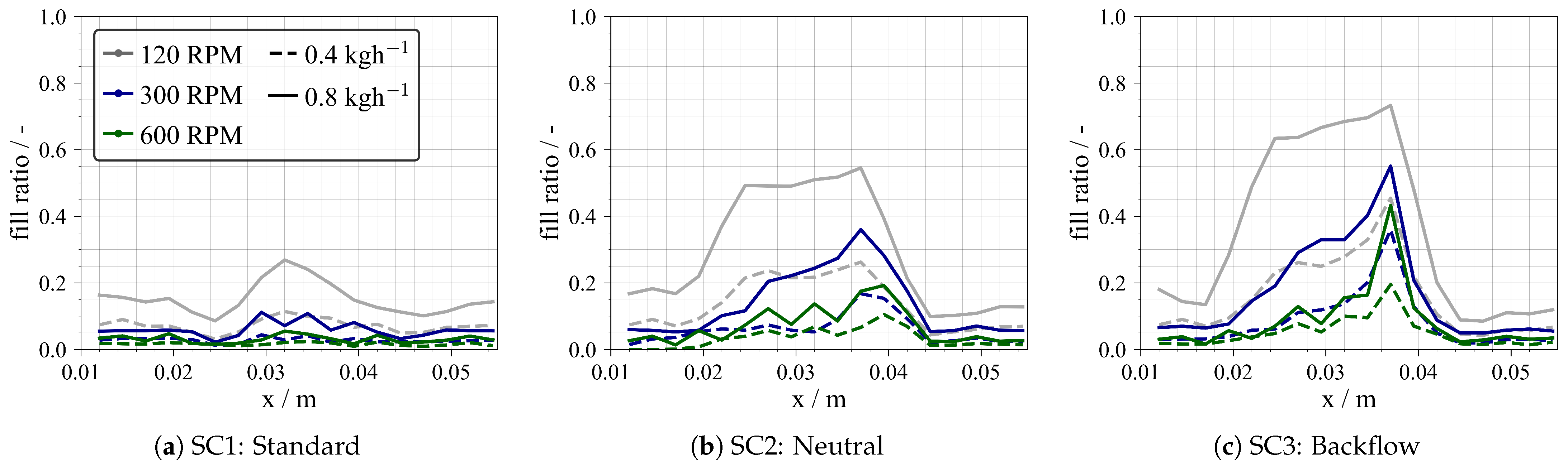
To quantify the resulting local filling ratio, the screws were discretized uniformly into 2.5 mm wide sections, which stands for the width of the single kneading disks. The fill ratio is then locally determined by the number of SPH particles in each discretized section divided by the maximum number of particles that would fit in a given screw section. This was numerically found to be approximately particles/mm at the used particle spacing of mm. The resulting filling profiles for the investigated screw configurations are shown in Figure 3.
The profiles show that the screw configuration has a significant effect on the material transport behavior. The use of a backward kneading block arrangement (Figure 3c) leads to overall higher filling of the kneading section. In addition, the material accumulates in front of the backward flow element, causing more uneven material distribution in the kneading zone. A higher filling ratio is also obtained by using a neutral kneading block, as shown in Figure 3b, where the kneading section is, in contrast, filled more evenly. For SC1, material retention is less appreciable, resulting in less-filled sections. Furthermore, for all evaluated screw sections, a higher fill ratio is achieved by using a lower screw rotational speed or higher flow rate. Therefore, in order to process more material without reaching exceedingly high filling ratios, the screw speed can be increased to extend the conveying capacity of the screw. However, this is subject to process limitations and also affects the residence time and material strain, which will be discussed below.
The residence time of the material in the extruder can be described by the response time of the device. Due to the flow conditions in the extruder and the interaction between the two shafts, material can be retained longer locally or can flow faster, depending on the screw design. As a result, the time it takes for particles entering the feed zone to reach the outlet cannot be described by a single value but rather as a frequency distribution. The residence time of individual particles affects the overall mixing efficiency of the extruder and, consequentially, the particle dispersion. As discussed above, the geometric differences of different screw elements introduce different local flow resistances, resulting in different local flow conditions within the extruder. Such local information is virtually impossible to measure experimentally. However, flow simulations of the screw sections allow analysis of local residence times and characterization of the effects of process changes such as screw speed, flow rates and screw configuration.
The calculation follows a Monte Carlo approach and is based on tracking a sample of individual particles as they enter the kneading zone and measuring the time it takes them to leave the kneader. However, depending on the flow conditions and screw design, different amounts of particles flow through the screw sections, causing variance in the sample size. Therefore, the sample size for each setup was set to be % of the particles entering the kneading section, or at least 100 particles to provide a representative sample size. Sampling occurs at steady state or when no further changes in the filling level of the kneading zone are detected. Figure 4 shows the resulting frequency distributions of the residence time in the kneading zone for all investigated process setups.
It can be observed that the screw configuration has a significant effect on the material residence time. The trends correlate with the ones discussed above for the filling ratio: according to the calculated filling ratios, particles are retained longer in the kneading section with backward elements (SC3) or neutral elements (SC2) compared to SC1. Lower screw speeds and higher mass flow rates additionally increase the residence time. Moreover, since all simulations resulted in partially filled screw sections, the screw speed has a larger effect on the residence time than the mass flow rate. This is in agreement with discussions from Kohlgrüber [11], wherein an analytical correlation for the mean residence time for both partially and fully filled screw sections was presented. The mean residence time can be approximated by
where correspond to the free volume of the extruder section, is the volume flow rate, and is the filling ratio. Equation (5) explains the variation in residence time for an increasing mass (or volume) flow rate. In the case of a fully filled screw section () the equation is reduced accordingly. However, for partially filled sections, the filling ratio term can be correlated to the screw speed, resulting in an inversely proportional relationship between the screw speed n and the residence time . Since all simulations resulted in partially filled screw sections, this explains the observed effects of screw speed. Thus, the results are in good agreement with theory [11]. Although a direct validation of the SPH studies is currently impossible due to the lack of analytical tools inside the extruder, this highlights that the obtained results are physically viable and that SPH is able to deliver trustworthy information on the flow conditions.
3.2. Specific Material Strain
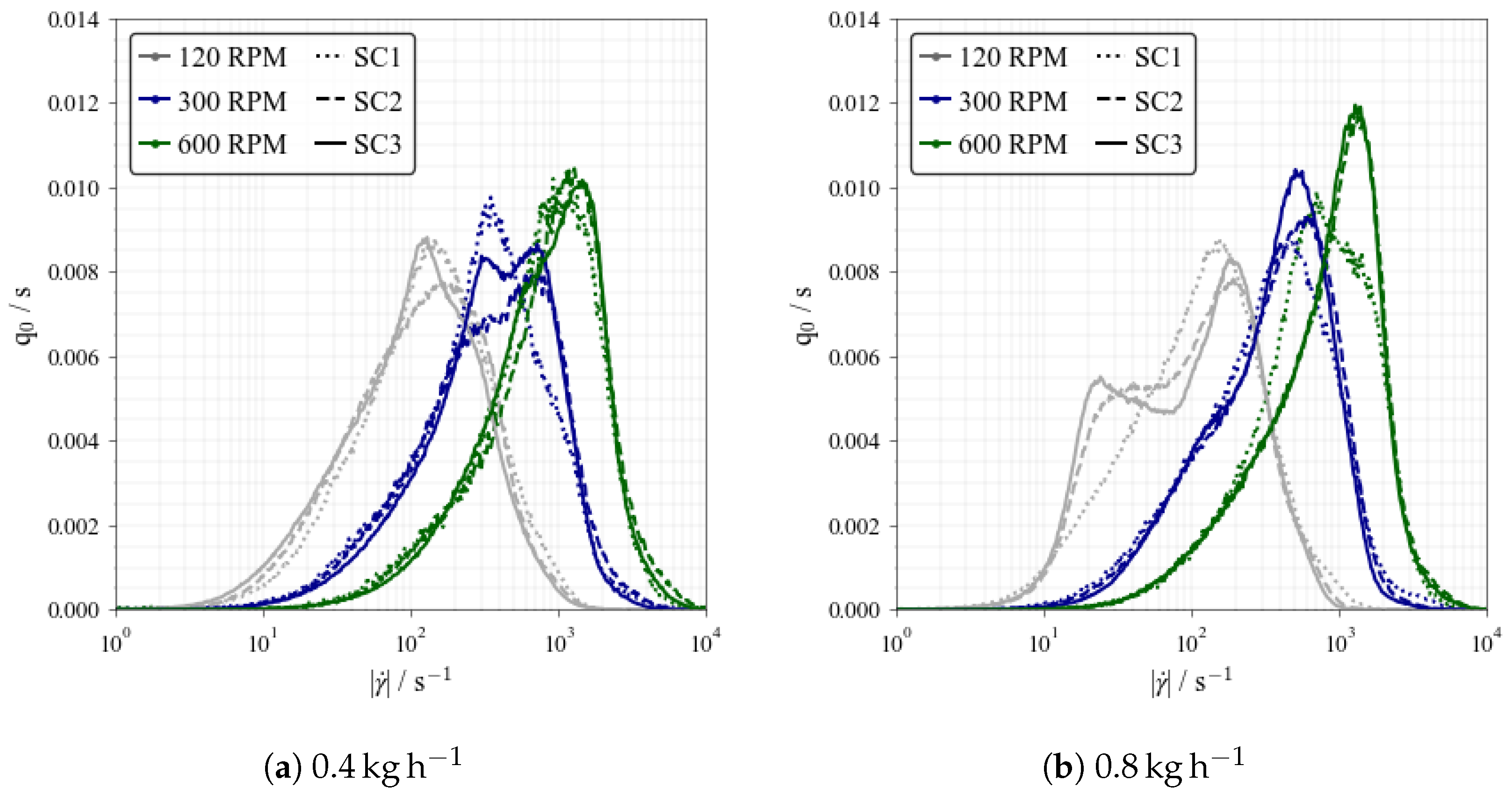
The process variations and the resulting flow conditions influence the amount of strain that the material undergoes during production. The relationship between fill ratio and shear rate for individual screw elements was discussed in our previous work based on a larger extruder [17]. In the present work, we further characterize the resulting material strain in relation to process parameters, but we also consider different screw configurations. This approach aims to understand the resulting strain conditions due to the interactions between different screw element combinations. Shear rates are calculated according to Equation (4) for all simulation cases based on 20 simulation frames (1 s real time) after reaching steady material flow in the kneader. Figure 5 shows the resulting shear rate distributions withing the kneading zone for the simulated process setups.
Considering changes to the screw speed at a constant flow rate, a shift of the curves to higher shear rate values with increasing screw speed can be observed. This behavior is consistent with the expectations based on analytical models of the mean shear rate for single-screw extruders [24]
where the dependence is described linearly. The term h is the gap size between screw and extruder barrel, and is the screw diameter. The influence of the screw speed in twin-screw extruders is similar to that in single-screw extruders, yet the effects of possible pressure gradients with twin screws lead to a more complex relationship, as discussed by Vergnes et al. [24]. For the evaluated twin-screw extruder with the applied process setups, the modes of the distributions increase linearly with the screw speed. Slight deviations from linear behavior can be explained by the effects of the screw speed on the filling ratio in the twin-screw section, as previously discussed. Again, this emphasizes the validity of the performed SPH simulations, as the observed trends are in agreement with theory.
Figure 5 illustrates that at a lower mass flow rate (0.4 ), smaller differences between the strain profiles are obtained, while at a higher mass flow rate (0.8 ), especially at lower screw speeds, the screw configuration causes larger differences in the material strain. This also correlates with the obtained filling ratios for these conditions. At lower mass flow rates, low filling ratios are obtained, causing higher material strain due to the predominant extruder wall and screw tip interaction. In contrast, as the mass flow rate increases, the material begins to fill the larger free spaces in the extruder cross section, resulting in lower strain rates for most of the additional material. Thus, the high-shear zones are already occupied by material, and the average strain is reduced. This effect dominates at lower screw speeds, where the effects of the filling ratio are more appreciable. Finally, considering that the investigated kneading zones have the same size, it can be observed that the arrangement of the kneading blocks in general slightly affects the material strain. However, no clear trends can be deduced, as the effects are highly dependent on the process parameters and are presumably related to the resulting filling ratios.
From the calculated shear rate distributions for the different process setups, further process-relevant values are derived. First, the mean specific shear stress ()
is evaluated as the mean value of the local shear stress divided by the mass flow rate . Additionally, the specific energy input was evaluated according to Equation (2). Thereby, the SEI includes the sum of all local drive power values evaluated according to Equation (3) that occur in the simulation for one second or 20 time steps. Therefore, the SEI represents a more global performance parameter of the individual screw configurations, and represents the mean local stress in the extruder. Figure 6 shows both the specific mean shear stress and the specific energy input in the kneading zone as a function of the screw speed for various screw configurations and mass flow rates.
As shown in Figure 6a, the specific mean shear stress increases with screw speed. In addition, the results indicate that the increase in stress depends on the screw configuration and the mass flow rate. Generally, the screw configuration with backwards elements (SC3) produces the highest stress, followed by SC2 and SC1, respectively. At higher mass flow rates, the differences in caused by the screw configuration are less pronounced than at lower flow rates. Additionally, since a lower mass flow rate results in a lower fill ratio and, thereby, less material being processed, the average stress induced by the screw on the material becomes higher. Similarly, Figure 6b shows that the simulated specific energy input (SEI) also increases with screw speed. Although the dependency on the screw configuration is less pronounced, SEI is still higher at lower flow rates due to the lower filling ratios in the extruder. SEI corresponds to the integral energy input; therefore, SEI includes the high- and low-stress areas in one value, resulting in similar values between screw configurations. Note that both and SEI are based on the shear rate calculations, with showing larger differences regarding the process setup and screw configuration; this value, however, reflects the mean stress and neglects the width of the shear rate distribution, which may be important for further dispersion evaluation.
3.3. Battery Dispersion Efficiency
In order to analyze the performance of the extruder on battery slurry production and to further study the effect of the process setups on the continuous wet mixing process, an experimental evaluation of the simulated operating points and screw configurations was conducted. In addition, a higher screw speed of 900 RPM was added for the experimental evaluation. For the experiments, a water-based graphite anode slurry with a solid content of dry mass was produced and analyzed. The measurements focused on changes to the particle size distribution (PSD) of the battery slurries after extrusion.
Figure 7 visualizes the effect of process parameters changes such as screw speed and flow rate for the analyzed screw configurations on the particle size distribution compared with the baseline distribution of dry components (Feed). Particle size distributions were measured using a LUMisizer (LUM GmbH). As analyses are based on light extinction, the results in multi-material systems have to be interpreted carefully since they neglect the influence of differences in extinction coefficients.
For all the investigated setups, particle dispersion is observed, as the peak for larger particle sizes is reduced while the peak for smaller sizes is increased relative to the feed material. The measurements show that particle dispersion occurs even at low screw speeds, yet the largest changes to particle size distribution are produced by increasing the screw speed. Thus, for a constant mass flow rate, the results indicate that increasing the screw speed causes an increase in fine particles in the mixture and, hence, higher breakage efficiency of the carbon black agglomerates. Sample SEM images comparing the produced anodes at low (120 RPM) and high (900 RPM) showing this effect can be found in Supplementary Materials. Moreover, this effect correlates with the increase in shear stress, since the shear rate generated by the screws increases almost linearly with the screw speed (see Section 3.2). In order to achieve breakage of the agglomerates in the battery slurry, a critical shear stress must be exceeded [18]. In addition, different agglomerate breakage mechanism may occur depending on the stress conditions. For instance, at low shear stress, erosion is more likely to occur, while at higher shear stress, more uniform particle breakage is feasible [18]. Although only empirical correlations exist, the breakage rate generally increases with increasing shear stress, i.e., energy dissipation [25].
The effect of the mass flow rate on the dispersion is analogous: When comparing the measured results at the same screw speed, an increase in mass flow rate resulted in a lower presence of fine material in the slurry. This can be explained by the increase in material flow in low-shear stress zones, as the filling ratio increases with the flow rate, as discussed in Section 3.2. Thus, the probability of larger agglomerates being processed in the narrow gaps of the extruder is reduced. Furthermore, a significant effect of screw configuration on the particle size distribution can be observed at lower flow rates. For the configuration with backward elements (SC3), the increased flow resistance can amplify the effects of the upstream kneader block and, combined with longer residence times, results in more breakage. For the other two screw configurations, however, this effect is less pronounced. Here, the use of the reference (SC1) or neutral (SC2) kneading block resulted in similar breakage performance. Despite the enhanced distributive mixing effect of neutral elements, the reduced breakage efficiency for both configurations can be explained by their similar dispersing effect [11]. In addition, the importance of screw configuration becomes more apparent at higher screw speeds, for which the shear stress is overall higher. For higher mass flow rates, the differences between screw configurations are less pronounced. This may be due to the overall lowered dispersion performance.
Finally, by comparing the particle size measurements at different process operating points, it is possible to summarize the effects of the process parameters on the dispersion efficiency. The dispersion index
proposed by Weber et al. [23] is employed for this analysis. The mean particle diameter of the left peak (fine material) in the slurry and its volume fraction (here, µm) are considered. The dispersion index is a general measure of the amount of finely dispersed carbon black aggregates in the mixture. In order to evaluate the effects of the individual process setups, the initial value of the dispersion index prior to extrusion for carbon black in the premix is subtracted, which in this study was equal to 0.52 µ for all experiments; this allows for a more objective assessment of the net increase in dispersion caused by the process. The resulting curves are shown in Figure 8, where the effects of screw speed, flow rate and screw configuration are visualized. It should be noted that changes in particle dispersion are mainly attributed to carbon black breakage, as for the investigated process conditions no large variation in the graphite particle sizes occurred (see Supplementary Material).
The results confirm that at constant flow rate, the increase in screw speed induces a higher degree of dispersion, which can be correlated with the increase in mean shear stress as shown in Figure 6. A similar effect can be seen with respect to the mass flow rate, since for the same screw speed, a lower flow rate results in a higher degree of dispersion, corresponding to the increase in shear stress as previously discussed. Furthermore, the effects of the screw configuration are also more appreciable for lower flow rates; here the dispersion of carbon black was higher when using backward elements (SC3) in comparison to SC1 and SC2, thus correlating also with the higher mean shear stress as shown in Figure 6. Accordingly, at higher flow rates, the screw effects are less pronounced, and the changes in the dispersion index are similar for all screw configurations.
The specific feed load (SFL) combines the effects of both screw speed and flow rate in a dimensionless number according to Equation (1). Plotting the dispersion index as a function of the inverse of the specific feed load yields a linear, dimensionless correlation for the extruder performance. Accordingly, it is possible to estimate the dispersion efficiency of the extruder based on target production rates. This correlation fits all investigated process conditions and screw configurations well, while a higher flow rate results in a slightly higher slope. However, the processing range at higher flow rates is shorter due to process limitations. Accordingly, it is possible to estimate and control the dispersion efficiency of the extruder based on the presented dimensionless correlation. Therefore, in order to increase the production rate while maintaining product quality, a higher screw speed must be applied, but this is limited by the process constraints of the extruder.
4. Discussion
The objective of this work was to analyze the effects of screw configuration and process parameters on the continuous production of lithium-ion battery slurries. An SPH-based simulation study of the slurry flow at different process conditions was performed and quantitatively evaluated. Material transport through the extruder and the resulting local filling ratios of different screw sections were characterized. The results showed that the screw design has a significant effect on the degree of filling of the extruder, especially in the kneading zone. The use of a counterflow kneading element (SC3) induced, as expected, a higher degree of filling in the kneading zone compared to the other evaluated kneader configurations. However, the simulations showed that, depending on the process parameters, uneven filling of the upstream screw element can occur, resulting in material accumulation only at the beginning of the downstream screw element. An increase in the filling ratio of the kneading section was also observed by using a neutral kneading block (SC2). In this case, more homogeneous filling of the kneading zone was obtained. Finally, the lowest filling levels were obtained with the reference screw (SC1).
Similar to the different filling ratios, the screw configuration also has a significant effect on the residence time. For the simulated mass flow rates and screw speeds, the residence time of particles in the kneading zone ranged from about ms to about s according to the obtained residence time distributions. The results showed that, in general, a higher degree of filling correlates with a longer residence time in the kneading zone. Thus, the particle retention characteristics of neutral (KB90) and backflow (KB60-R) elements were significantly higher compared to the reference screw designs. Since all configurations in the evaluated process range resulted in a partially filled section of the kneading zone, the effect of screw speed was higher than the effect of mass flow rate, which is consistent with the literature.
To investigate the material strain in the extruder, shear rate distributions were calculated, which showed a strong dependence on the process conditions, again correlating with the effects on the filling ratio. At high screw speeds and low mass flow rates, i.e., at lower filling ratios in the kneading section, the magnitude of the shear rates in the flow is increased, thereby promoting higher local stress for particle dispersion. Thus, at higher filling ratios, the probability of material being processed in the high-shear areas is reduced. The screw configuration showed a significant effect on the mean shear stress, especially at low flow rates, for which the backwards configuration showed the highest mean shear stress. In contrast, for higher flow rates, the influence of the screw configurations was less pronounced. In general, the results showed the dependency of the mean shear stress for different process setups, thus demonstrating that processing material at a lower flow rate and higher screw speed increases the amount of strain in the flow, thereby promoting higher local stress for particle dispersion.
In addition to the simulations, an experimental analysis of the slurry quality after extrusion was conducted. For this purpose, graphite anode slurries were processed under the same process conditions that were simulated. The slurry quality was evaluated by measuring the changes to the particle size distribution. The results are consistent with the previously discussed dependence of material strain on filling ratio: at lower mass flow rates and higher screw speeds, i.e., at low filling ratios, the break-up of larger carbon black agglomerates is promoted, resulting in an increased amount of finely dispersed particles after extrusion. Both effects were summarized using the dimensionless flow number or specific feed load (SFL). It was shown that a high flow number induces a lower degree of dispersion. Therefore, low flow rates and high screw speeds should be used to improve dispersion for the extrusion of battery slurries. The presented dimensionless correlation allows the estimation of the dispersion degree of conductive material in the slurries directly from the process parameters for the evaluated extruder. It is therefore a valuable tool for scaling production rates while maintaining the desired degree of dispersion. Since a higher flow rate reduces the degree of dispersion in the slurry, increasing the screw speed to maintain a constant SFL can be used to mitigate changes in particle dispersion. The same simulation procedure can be applied to other extruder scales, for which the results should be comparable under the same process conditions. Furthermore, if other materials such as cathodes are considered, similar behavior is expected as long as the changes to the degree of dispersion can be attributed to the conductive material. For the same process parameters, similar shear rates should be obtained; however, depending on the formulation of the paste (viscosity), the shear stress may change. The present work covers one anode formulation in order to concentrate on the process parameters.
Further studies should aim to close the gap between the presented shear rate distributions and the experimentally observed changes to the particle size distribution. Population balance equations pose a promising way of coupling the results of the presented SPH simulations (process conditions) and the desired slurry quality (particle dispersion). Such a multi-scale approach would result in an end-to-end modeling framework for simulating slurry dispersion in twin-screw extruders for battery applications.
Supplementary Materials
The following supporting information can be downloaded at: https://www.mdpi.com/article/10.3390/batteries10050145/s1, Figure S1: SEM image of the produced anode slurries at 120 RPM (a) and 900 RPM (b); Figure S2: Particle size distributions of graphite after extrusion at different screw speeds, compared to the initial distribution (Feed).
Author Contributions
Conceptualization, J.F.M.G.; methodology, J.F.M.G. and F.R.; software, J.F.M.G.; validation, J.F.M.G.; formal analysis, J.F.M.G.; investigation, J.F.M.G.; resources, H.N.; data curation, J.F.M.G.; writing—original draft preparation, J.F.M.G.; writing—review and editing, F.R. and H.N.; visualization, J.F.M.G. and F.R.; supervision, F.R. and H.N.; project administration, J.F.M.G.; funding acquisition, F.R. and H.N. All authors have read and agreed to the published version of the manuscript.
Funding
This research was funded by the Federal Ministry of Education and Research (Bundesministerium für Bildung und Forschung [BMBF]), grant number 03XP0369A.
Data Availability Statement
The data that support the findings of this study are available from the corresponding author upon reasonable request.
Acknowledgments
Support from Project Management Jülich [PTJ] within the research cluster InZePro is highly acknowledged. Moreover, the authors acknowledge support from the state of Baden–Württemberg through bwHPC and the KIT–Publication Fund of the Karlsruhe Institute of Technology. Thermo Fisher Scientific is acknowledged for machinery provision.
Conflicts of Interest
The authors declare no conflicts of interest.
Abbreviations
The following abbreviations are used in this manuscript:
| SEI | Specific Energy Input |
| SFL | Specific Feed Load |
| SPH | Smoothed-Particle Hydrodynamics |
| TSE | Twin-Screw Extruder |
References
- Li, J.; Fleetwood, J.; Hawley, W.B.; Kays, W. From Materials to Cell: State-of-the-Art and Prospective Technologies for Lithium-Ion Battery Electrode Processing. Chem. Rev. 2022, 122, 903–956. [Google Scholar] [CrossRef] [PubMed]
- Fernandez-Diaz, L.; Castillo, J.; Sasieta-Barrutia, E.; Arnaiz, M.; Cabello, M.; Judez, X.; Terry, A.; Otaegui, L.; Morant-Miñana, M.C.; Villaverde, A. Mixing methods for solid state electrodes: Techniques, fundamentals, recent advances, and perspectives. Chem. Eng. J. 2023, 464, 142469. [Google Scholar] [CrossRef]
- Wang, M.; Dang, D.; Meyer, A.; Arsenault, R.; Cheng, Y.T. Effects of the Mixing Sequence on Making Lithium Ion Battery Electrodes. J. Electrochem. Soc. 2020, 167, 100518. [Google Scholar] [CrossRef]
- Grießl, D.; Adam, A.; Huber, K.; Kwade, A. Effect of the Slurry Mixing Process on the Structural Properties of the Anode and the Resulting Fast-Charging Performance of the Lithium-Ion Battery Cell. J. Electrochem. Soc. 2022, 169, 020531. [Google Scholar] [CrossRef]
- Hoffmann, A.; Heider, E.A.; Dreer, C.; Pfeifer, C.; Wohlfahrt-Mehrens, M. Influence of the Mixing and Dispersing Process on the Slurry Properties and the Microstructure and Performance of Ultrathick Cathodes for Lithium–Ion Batteries. Energy Technol. 2023, 11, 2200484. [Google Scholar] [CrossRef]
- Ventura Silva, G.; Thomitzek, M.; Lippke, M.; Heckmann, T.; Karaki, H.; Lischka, C.; Möhlen, F.; Mayer, D.; Hagemeister, J.; Daub, R.; et al. Digitalization Platform for Sustainable Battery Cell Production: Coupling of Process, Production, and Product Models. Energy Technol. 2023, 11, 2200801. [Google Scholar] [CrossRef]
- Reynolds, C.; Faraji Niri, M.; Hidalgo, M.F.; Heymer, R.; Román, L.; Alsofi, G.; Khanom, H.; Pye, B.; Marco, J.; Kendrick, E. Impact of Formulation and Slurry Properties on Lithium–ion Electrode Manufacturing. Batter. Supercaps 2023, 7, e202300396. [Google Scholar] [CrossRef]
- Zapata Dominguez, D.; Xu, J.; Boudjema, Y.; Ben Hadj Ali, S.; Zanotto, F.M.; Franco, A.A. Influence of the mixing speed in the rheology of NMC622-based Li-ion battery electrode slurries. J. Power Sources Adv. 2024, 26, 100141. [Google Scholar] [CrossRef]
- Haarmann, M.; Grießl, D.; Kwade, A. Continuous Processing of Cathode Slurry by Extrusion for Lithium–Ion Batteries. Energy Technol. 2021, 9, 2100250. [Google Scholar] [CrossRef]
- Wiegmann, E.; Cavers, H.; Diener, A.; Kwade, A. Semi–Dry Extrusion–Based Processing for Graphite Anodes: Morphological Insights and Electrochemical Performance. Energy Technol. 2023, 11, 2300341. [Google Scholar] [CrossRef]
- Kohlgrüber, K. Co-Rotating Twin-Screw Extruders Fundamentals, 1st ed.; Hanser Publications: Cincinnati, OH, USA, 2019. [Google Scholar]
- Eitzlmayr, A.; Koscher, G.; Reynolds, G.; Huang, Z.; Booth, J.; Shering, P.; Khinast, J. Mechanistic modeling of modular co-rotating twin-screw extruders. Int. J. Pharm. 2014, 474, 157–176. [Google Scholar] [CrossRef] [PubMed]
- Eitzlmayr, A.; Matić, J.; Khinast, J. Analysis of flow and mixing in screw elements of corotating twin–screw extruders via SPH. Aiche J. 2017, 63, 2451–2463. [Google Scholar] [CrossRef]
- Lewandowski, A.; Wilczyński, K.J.; Nastaj, A.; Wilczyński, K. A composite model for an intermeshing counter–rotating twin–screw extruder and its experimental verification. Polym. Eng. Sci. 2015, 55, 2838–2848. [Google Scholar] [CrossRef]
- Paredes-Goyes, B.; Zanotto, F.M.; Boudeville, V.; Grugeon, S.; Dupont, L.; Franco, A.A. Mesoscopic Model of Extrusion during Solvent–Free Lithium–ion Battery Electrode Manufacturing. Batter. Supercaps 2024, 7, e202300441. [Google Scholar] [CrossRef]
- Ellwanger, F.; Pernice, L.; Karbstein, H.P.; Emin, M.A. Investigating local residence time and thermomechanical stress profile in twin-screw extrusion of plant proteins by using the moving particle semi-implicit simulation method. J. Food Eng. 2023, 359, 111665. [Google Scholar] [CrossRef]
- Meza Gonzalez, J.F.; Nirschl, H. Numerical Investigation of the Local Shear Rate in a Twin–Screw Extruder for the Continuous Processing of Li–Ion Battery Electrode Slurries. Energy Technol. 2023, 11, 2201517. [Google Scholar] [CrossRef]
- Asylbekov, E.; Mayer, J.; Nirschl, H.; Kwade, A. Modeling of Carbon Black Fragmentation During High–Intensity Dry Mixing Using the Population Balance Equation and the Discrete Element Method. Energy Technol. 2023, 11, 2200867. [Google Scholar] [CrossRef]
- Winck, J.; Gottschalk, T.; Thommes, M. Predicting Residence Time and Melt Temperature in Pharmaceutical Hot Melt Extrusion. Pharmaceutics 2023, 15, 51417. [Google Scholar] [CrossRef] [PubMed]
- Jeschull, F.; Brandell, D.; Wohlfahrt-Mehrens, M.; Memm, M. Water-Soluble Binders for Lithium-Ion Battery Graphite Electrodes: Slurry Rheology, Coating Adhesion, and Electrochemical Performance. Energy Technol. 2017, 5, 2108–2118. [Google Scholar] [CrossRef]
- Yildiz, T.; Wiechers, P.; Nirschl, H.; Gleiß, M. Direct recycling of carbon black and graphite from an aqueous anode slurry of lithium-ion batteries by centrifugal fractionation. Next Energy 2024, 2, 100082. [Google Scholar] [CrossRef]
- Domínguez, J.M.; Fourtakas, G.; Altomare, C.; Canelas, R.B.; Tafuni, A.; García-Feal, O.; Martínez-Estévez, I.; Mokos, A.; Vacondio, R.; Crespo, A.J.C.; et al. DualSPHysics: From fluid dynamics to multiphysics problems. Comput. Part. Mech. 2022, 9, 867–895. [Google Scholar] [CrossRef]
- Weber, M.; Mayer, J.K.; Kwade, A. The Carbon Black Dispersion Index DI CB: A Novel Approach Describing the Dispersion Progress of Carbon Black Containing Battery Slurries. Energy Technol. 2023, 11, 2201299. [Google Scholar] [CrossRef]
- Vergnes, B. Average Shear Rates in the Screw Elements of a Corotating Twin-Screw Extruder. Polymers 2021, 13, 304. [Google Scholar] [CrossRef] [PubMed]
- Jeldres, R.I.; Fawell, P.D.; Florio, B.J. Population balance modelling to describe the particle aggregation process: A review. Powder Technol. 2018, 326, 190–207. [Google Scholar] [CrossRef]
Figure 1.
Overview of modeled screw configurations for inducing flow resistance. Standard configuration (a) with 30° and 60° offset angle disks (low resistance), neutral configuration (b) with 60° and 90° offset angle disks (moderate resistance), and backflow configuration (c) with 60° and reversed 60° offset angle disks (high resistance).

Figure 2.
Rendering of the material distribution and resulting axial velocity in response to changes to the process parameters for a screw configuration with backflow kneading section (SC3) for both and at respectively 120, 300 and 600 RPM.
Figure 2.
Rendering of the material distribution and resulting axial velocity in response to changes to the process parameters for a screw configuration with backflow kneading section (SC3) for both and at respectively 120, 300 and 600 RPM.

Figure 3.
Resulting filling ratios in the screw with respect to configuration and process parameters: (a) standard, (b) neutral and (c) backflow configurations.
Figure 3.
Resulting filling ratios in the screw with respect to configuration and process parameters: (a) standard, (b) neutral and (c) backflow configurations.

Figure 4.
Residence time distribution in the kneading zone for different process variations and screw configurations: standard (SC1), neutral (SC2) and backflow (SC3) configurations.
Figure 4.
Residence time distribution in the kneading zone for different process variations and screw configurations: standard (SC1), neutral (SC2) and backflow (SC3) configurations.

Figure 5.
Effects of screw configuration and process parameters on the shear rate distributions in the kneading section: standard (SC1), neutral (SC2) and backflow (SC3) configurations.
Figure 5.
Effects of screw configuration and process parameters on the shear rate distributions in the kneading section: standard (SC1), neutral (SC2) and backflow (SC3) configurations.

Figure 6.
Effect of the screw speed on the specific mean shear stress (a) and the total specific energy input (b) for the evaluated kneading sections for mass flow rates of both (SC1–SC3) and (SC1*–SC3*): standard (SC1), neutral (SC2) and backflow (SC3) configurations.
Figure 6.
Effect of the screw speed on the specific mean shear stress (a) and the total specific energy input (b) for the evaluated kneading sections for mass flow rates of both (SC1–SC3) and (SC1*–SC3*): standard (SC1), neutral (SC2) and backflow (SC3) configurations.

Figure 7.
Effects of the process parameters and screw configuration on the particle size distribution (equivalent diameter x*) of the produced anode slurry compared to the feed distribution: standard (SC1), neutral (SC2) and backflow (SC3) configurations.
Figure 7.
Effects of the process parameters and screw configuration on the particle size distribution (equivalent diameter x*) of the produced anode slurry compared to the feed distribution: standard (SC1), neutral (SC2) and backflow (SC3) configurations.

Figure 8.
Effect of the screw speed (left) and specific feed load (right) on the carbon black dispersion index for the evaluated kneading sections for both mass flow rates of (SC1–SC3) and (SC1*–SC3*): standard (SC1), neutral (SC2) and backflow (SC3) configurations.
Figure 8.
Effect of the screw speed (left) and specific feed load (right) on the carbon black dispersion index for the evaluated kneading sections for both mass flow rates of (SC1–SC3) and (SC1*–SC3*): standard (SC1), neutral (SC2) and backflow (SC3) configurations.

Disclaimer/Publisher’s Note: The statements, opinions and data contained in all publications are solely those of the individual author(s) and contributor(s) and not of MDPI and/or the editor(s). MDPI and/or the editor(s) disclaim responsibility for any injury to people or property resulting from any ideas, methods, instructions or products referred to in the content. |
© 2024 by the authors. Licensee MDPI, Basel, Switzerland. This article is an open access article distributed under the terms and conditions of the Creative Commons Attribution (CC BY) license (https://creativecommons.org/licenses/by/4.0/).
Share and Cite
MDPI and ACS Style
Meza Gonzalez, J.F.; Nirschl, H.; Rhein, F. Continuous Anode Slurry Production in Twin-Screw Extruders: Effects of the Process Setup on the Dispersion. Batteries 2024, 10, 145. https://doi.org/10.3390/batteries10050145
AMA Style
Meza Gonzalez JF, Nirschl H, Rhein F. Continuous Anode Slurry Production in Twin-Screw Extruders: Effects of the Process Setup on the Dispersion. Batteries. 2024; 10(5):145. https://doi.org/10.3390/batteries10050145
Chicago/Turabian StyleMeza Gonzalez, Juan Fernando, Hermann Nirschl, and Frank Rhein. 2024. "Continuous Anode Slurry Production in Twin-Screw Extruders: Effects of the Process Setup on the Dispersion" Batteries 10, no. 5: 145. https://doi.org/10.3390/batteries10050145
Note that from the first issue of 2016, this journal uses article numbers instead of page numbers. See further details here.