Effect of Operating Temperature on Individual Half-Cell Reactions in All-Vanadium Redox Flow Batteries


SGL Carbon GmbH, Werner-von-Siemens-Straße 18, D-86405 Meitingen, Germany
*
Author to whom correspondence should be addressed.
Batteries 2018, 4(4), 55; https://doi.org/10.3390/batteries4040055
Submission received: 26 September 2018
/
Revised: 29 October 2018
/
Accepted: 30 October 2018
/
Published: 1 November 2018
(This article belongs to the Special Issue Vanadium Redox Flow Battery and Its Applications)
Abstract
:Systematic steady-state measurements were performed in order to investigate the effect of operating temperature on the individual half-cell reactions in all vanadium redox flow cells. Results confirm that the kinetic losses are dominated by the negative half-cell reaction. Steady-state polarization and AC impedance measurements allowed for extraction of kinetic parameters (exchange current densities, activation energy) of the corresponding half-cell reaction.
1. Introduction
Redox flow battery technology lends itself to large-scale storage of energy harvested from intermittent sources such as wind or solar power [1,2,3,4]. The appeal of this technology is related to its prospects of a high degree of modularity, fast response time, inherent safety and prolonged cycle life [5,6,7]. Despite the multitude of different chemistries proposed in recent years [8], by far the dominant type used in commercial systems is the all-vanadium redox flow battery (VRFB) already introduced by M. Skyllas-Kazacos in the 1980s [9,10]. The well-founded advantage of the VRFB lies in the use of different redox states of a single element species to drive both half-cell reactions. As a consequence, capacity losses caused by the undesired crossover of active materials can be conveniently regenerated in a subsequent charge/discharge cycle. On the other hand, some of the vanadium species involved suffer from limited solubility, thus restricting energy density. Another concern is related to the precipitation of high valence vanadium oxides (mostly V2O5), which becomes progressively problematic at operating temperatures above 40 °C in common VRFB electrolytes [11].
Notwithstanding the above, VRFB has attained the highest degree of technical and commercial maturity of all flow battery types. For a large part, this preeminence has been nurtured by a wealth of research and development activities carried out with respect to improved vanadium electrolytes [11,12], ion-exchange membranes with both high conductivity and selectivity [13,14], more efficient electrodes [15], as well as on a wide spectrum of theoretical approaches [16,17,18,19] to understand the rather complex interactions which govern the performance and lifetime of VRFBs.
Temperature plays a pivotal role with respect to the stability of the vanadium electrolyte. Hence, the main effort has been focused on developing more concentrated vanadium electrolytes which facilitate VRFB operation within a larger temperature window [20]. In terms of the effects of cell temperature on electrochemical processes in VRFBs, scholarly references are relatively scarce. As expected, model studies on graphite electrodes show more favorable kinetics at an elevated temperature for the positive redox couple [21]. Langner et al. [22] studied the electrochemistry of the negative redox couple (V2+/V3+) at more practically relevant (carbon felt) electrodes by means of cyclic voltammetry. They found indications that parasitic side reactions such as hydrogen evolution might become increasingly problematic at elevated temperatures. Similar observations were made in actual cells using reference electrodes to monitor the overpotentials [23] or by visualization of the formed hydrogen bubbles in transparent cells [24]. Single cell studies revealed a 90 mW∙cm−2 peak power gain by increasing the operating temperature from 15 °C to 55 °C [25]. This gain in power density, however, was almost nullified by lower coulombic efficiency and a rapid drop in capacity. Xi et al. [26,27] studied single cells from −20 °C up to 50 °C. They found almost constant voltage efficiency from 30°C to 50°C, while the coulombic efficiency steadily decreased with increasing cell temperature due to vanadium crossover. Overall, an operating temperature of 40 °C has been suggested for optimum electrolyte utilization. Finally, modelling studies have been performed to predict the evolution of cell temperature depending on components and operational parameters [28].
To arrive at a more detailed understanding of the impact of temperature on VRFB performance, knowledge of the temperature effect on the individual half-cells is a crucial aspect—particularly because the redox chemistry of both half-cell couples is significantly different. For instance, the V2+/V3+ redox couple (negative) is known as a typical inner-sphere redox system which has rather poor kinetics on carbon and which is inherently sensitive to surface oxygen groups on the carbon fibers. Moreover, the negative half-cell reaction is affected by parasitic side reactions such as hydrogen formation [23,29]. Consequently, Bourke et al. [30] found substantial differences in the kinetics of the negative electrode depending on oxidative or reductive pretreatment. Previous studies in our lab confirmed correlations between the number of surface oxygen groups (e.g., -C=O) and the kinetics (exchange current densities normalized to the BET surface area) of the negative couple [31]. By contrast, the redox chemistry of V(IV) and V(V) species is very complex (i.e., multistep reaction pathways) [32] and displays a dependence of the reactivity on the graphitic character of the carbon electrode [31,33]. This study investigates the effects of the operating temperature on the individual half-cell reactions by means of steady-state (double half-cell) measurements [31,34,35] with both redox couples. Experiments were carried out in each case with two Nafion® membranes (Ion Power, Munich, Germany) with the same properties but different thickness in order to quantify the membrane contributions.
2. Results
2.1. Full Cell Test
Figure 1 shows the typical performance parameters of a full cell at three different temperatures.
The observed trends corroborate the findings of previous studies. The increase in voltage efficiency in line with temperature can be attributed to better ionic conductance (porous electrode and membranes) as well as to faster charge-transfer kinetics. This beneficial trend comes at the expense of a lower current efficiency at elevated temperature, which is a result of an increased crossover of vanadium species [25]. The cell temperature of 35 °C yielded the best compromise between voltage and current efficiency (product of both yields the highest value). The observed effects on voltage and coulombic efficiency were very similar to studies using other types of membranes [25,26,36]. In the main part of this study, we present a methodology to break down the temperature effects on the corresponding half cells.
2.2. Effects on Porous Electrode
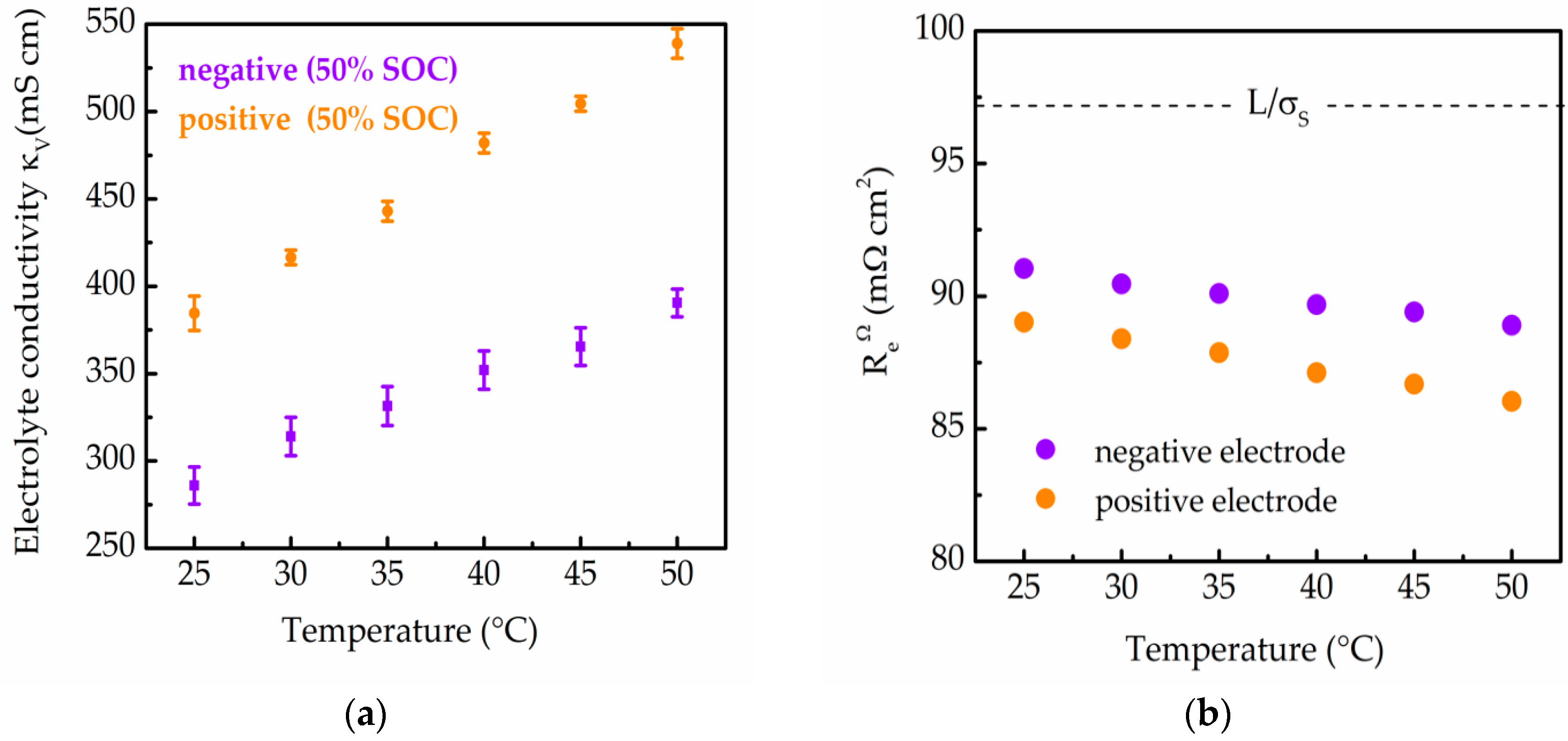
As the porous electrode constitutes a mixed conductor (electronic and ionic transport), the resistance is determined by the electronic conductivity of the fibrous skeleton and the ionic conductivity within its voids The latter was calculated based on the measured bulk conductivity of the vanadium electrolyte ) and the porosity of the compressed felt ) using a Bruggeman approximation [19].
Figure 2a shows the area-specific ionic resistance (L/) calculated based on electrolyte conductivities (), Figure 2b) measured at different temperatures (L is the thickness of the porous electrode). As expected, the ionic conductivity of the porous electrode is more than one order of magnitude lower than its electronic conductance and increases with temperature. The total Ohmic resistance of the porous electrode is then given by a parallel combination of two resistors (L/ and L/).
Figure 2 shows the measured electrolyte conductivities and the calculated ohmic resistances (Equation (2)) of the porous electrodes at different temperatures.
As expected, the conductivities of both half-cell electrolytes increase with temperature as shown in previous studies [37].
2.3. Double Half-Cell Measurements
In order to assess the charge transfer kinetics, we applied the method of double half-cell measurements (DHC) recently introduced by Darling and Perry [34,35]. This simple method features the same electrolyte composition in both half cells (either V2+/V3+ or VO2+ /VO2+), meaning that it mimics a vanadium redox flow battery which is at steady-state conditions (i.e., operating at constant state of charge). Such measurements are particularly useful since concentration polarization is negligible, and due to the use of the same redox species on both electrodes, the dissection of the voltage losses is vastly simplified. Additionally, potential crossover of species does not lead to a distortion of the electrode performance parameters, which occurs in cycling studies on full cells. In our previous work, we have successfully employed this method to study different carbon felt type electrodes with respect to their catalytic activity for both half-cell reactions [31].
Upon passing a current ) through such a cell, the potential of the double-half cell ) with a geometric area is given by
contains contributions from the resistance of the ion-exchange membrane ), the contact and collector resistances ) and the resistance of the porous electrodes )
Re comprises Ohmic resistances and overpotentials associated with charge-transfer kinetics. The high-frequency impedance , which is typically taken from the impedance spectra section where AC voltages and currents are in phase at high frequencies (HF), yields the purely conductive (Ohmic) losses of the cell [38]
In accordance with the widely-known 1D porous electrode model developed by Newman [39], the total resistance of either electrode ), which contains Ohmic and kinetic elements, can be approximated by
with y being a dimensionless quantity describing the rate of charge transfer
Equation (6) holds for linear polarization, a condition which applies to DHCs. As it is rather difficult to determine the (active) surface area () of the porous electrode accurately [40,41], the volumetric exchange current density ( · ) [38] is used as a quantity describing the charge-transfer kinetics ( values of virgin carbon felts are typically around 500 cm−1). Fitting the experimentally accessible values of double-half cell resistance ) and high-frequency impedance to Equation (8) allows for the calculation of kinetic parameters (y).
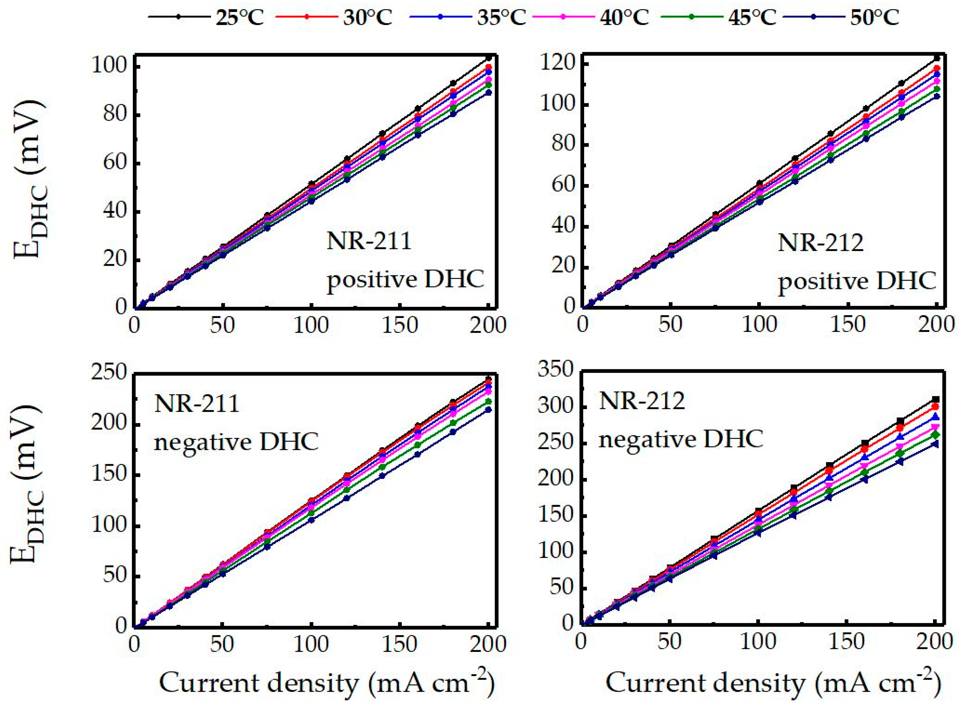
Figure 3 shows the polarization curves of negative and positive double half-cells using Nafion® NR-211 and NR-212 ion exchange membranes. As expected, the positive double-half cells show a significantly lower DHC resistance due to the higher conductivity of the positive electrolyte and the faster kinetics of the positive couple. This is highly consistent with previous studies [29,41,42,43]. Similarly, a clear distinction between DHCs built using NR-211 and NR-212 membranes is observed.
The difference in DHC resistance can be used in order to quantify the effect of the membrane on the DHC resistance (see Supplementary Figure S1), since the specific conductivities of both membranes can be assumed to be identical. Taking the average value of the difference between positive and negative DHCs, we can estimate, for a full cell at SOC = 50%, an area-specific resistance (ASR) of a Nafion® NR-212 of 321 mΩ∙cm2 (30 °C) and 252 mΩ∙cm2 (50 °C). These values are consistent with values reported in the literature [44,45]. Fitting the experimentally determined resistance and impedance values (Figure 4a) and material parameters (, , ε) to Equation (8), the volumetric exchange current densities ( · ) could be obtained for both half-cell reactions (Figure 4b).
Volumetric exchange current densities ( · ) of negative and positive couples differ by almost two orders of magnitude (ratio positive to negative of between 40 and 51 depending on the temperature). A similar ratio has been observed in previous investigations, which performed a deconvolution of voltage losses by means of single-electrode impedance spectroscopy and reference electrodes [42,43]. For the sake of comparison with previous studies based on different methodologies, we estimated by multiplying the BET surface area of the felt (3.8 m2 g‒1) by its bulk density (0.09 g cm−3). This yields exchange current densities related to the geometric area of between 0.09 and 0.14 mA cm−2geo for the negative and between 3.5 and 7.7 mA∙cm−2geo for the positive couple. These values are highly consistent with previous findings, which report 0.15/4.3 mA∙cm−2geo and 0.149/6.65 mA∙cm−2geo (ratio of positive to negative of 44) [46]. As the temperature dependence follows an Arrhenius-type behaviour for both redox couples, the activation energy ΔH≠ can readily obtained by differentiation
The values found (18.5 kJ∙Mol−1 for V2+/V3+ and 24.6 kJ∙Mol−1 for VO2+/VO2+) are comparable to values gained from impedance analysis (charge-transfer resistance) of single electrodes [37].
3. Discussion
The effect of operating temperature on both half-cell reactions in vanadium redox flow batteries was studied by means of steady-state measurements. This methodology facilitates the evaluation of the temperature effect on the individual redox reactions in VRFBs. It has been confirmed that, even for surface-treated electrodes, the rate of charge-transfer of the negative half-cell reactions are around 50 times lower than those for the positive half-cell. Both half-cells showed a linear increase in the rate of charge transfer with cell temperature, which allows for the calculation of the activation energy. The latter was on a similar level for both redox couples. Taking the temperature dependence of the voltage losses associated with both half-cells from this study we can make simple estimations on the effect of full cell resistance. For a VRFB cell with a Nafion® N212 membrane this amounts to a drop in cell resistance of 78 mΩ∙cm2 per 10 K temperature increase. This value is comparable to the actual full cell data obtained using Fumasep® membranes (Figure 1a), for which a temperature increment of 10 K produced a reduction in cell resistance of 87 mΩ∙cm2.
Our current efforts extend this approach to the study of ageing of carbon felt electrodes in vanadium redox flow batteries.
4. Materials and Methods
All cells were built using commercially available materials. Surface-treated SIGRACELL® GFD 4.6 carbon felts (SGL Carbon, Meitingen, Germany) were used as electrode materials as described in Reference [29]. Glassy carbon (Sigradur®, HTW, Thierhaupten, Germany, 2 mm) was chosen as the plate material for the full cell test as it is more stable at high SOC than graphite (which is prone to exfoliation). Full cell tests were carried out with an anion-exchange membrane (Fumasep® FAP450, Fumatech, Bietigheim, Germany). A commercial vanadium electrolyte (1.6 M vanadium in 2 M sulfuric acid, GFE, Nuremberg, Germany) was used in all tests. Prior to DHC measurements, negative and positive electrolytes were adjusted to a state of charge (SOC) of 50% in a separate full cell. The SOC of the electrolytes was validated by measurements using a glassy carbon electrode against a saturated mercury sulfate reference electrode (SMSE, = +0.658 V) prior to DHC tests. All experiments were conducted using homebuilt cells with active areas of 20 cm2. The cells were assembled applying a felt compression to 75 ± 1% with respect to the uncompressed thickness (4.7 mm, ). L refers to the actual thickness of the porous electrode (distance from the separator to the current collector). The porosity of the electrode (ε) results as follows
With a porosity of the uncompressed felt () of 0.945 (determined by mercury intrusion), we obtained a felt of 0.927 for the compressed electrode (ε). Full cell tests were performed using charge-discharge cycles at current densities with the end of charge/discharge being controlled by means of an open-circuit voltage (OCV) cell which was put in in series with the operating cell as described previously. For the OCV, a temperature coefficient of 1.6 mV∙K−1, which is consistent with published values and our own calibration measurements, was used. Galvanostatic charge-discharge cycling tests were performed between 10% and 90% SOC. Electrolyte circulation was maintained by two Liquiport® diaphragm pumps (KNF Neuberger, Freiburg, Germany) operating at flow rates of 90 mL min−1. A modified Scribner 857 flow battery test setup (Northern Pines, NC, USA) was used to record the current-voltage curves. The temperature was controlled by putting both electrolyte tanks in a thermostat bath. For double half-cells (DHCs), two cation exchange membranes (Nafion® NR-211 and NR-212, Ion Power, Munich, Germany) were used. SIGRACELL® TF6 flexible graphite plates (0.6 mm, SGL Technic, Valencia, CA, USA) served as current collectors in double half-cell measurements. Polished 2 mm copper plates, which served as current collector terminals, were each equipped with two screw contacts and leads (voltage and current).
The conductivity of the electrolyte was monitored during the tests (Mettler Toledo, Urdorf, Switzerland). Impedance spectra (amplitude 10 mV rms, 0.1 Hz to 100 KHz) were recorded at open-circuit potential before and after measurement of the polarization curves by means of a Solartron 1270/1260 potentiostat/frequency response analyzer. Measurements were carried out using Nafion® NR-211 (dry thickness 25 µm) and Nafion® NR-212 (dry thickness 51 µm), respectively. The membranes were equilibrated using alternating constant current cycling for 10 min. The area-specific electronic resistance of the porous electrode (L/) was obtained from two-point measurements with gold-plated contacts. Rcc was determined to 30 ± 5 mΩ∙cm2 using plate/felt sandwiches with 4 different felts (variable thickness but identical porosity) and extrapolation to zero felt thickness [47]. Complementary measurements with a ‘dry’ cell (VRFB cell assembled without membrane) using the same felt compression level showed that the values are consistent.
Supplementary Materials
The following are available online at https://www.mdpi.com/2313-0105/4/4/55/s1, Figure S1: Difference in resistance of positive and negative DHCs using NR-211 and NR-212 membranes at different temperatures.
Author Contributions
Conceptualization, visualization, validation, manuscript writing, R.S.; Cell building and data acquisition, C.M. and D.D.; Test bench maintenance, C.M.
Acknowledgments
The authors thank Swati Poduval (now at Konrad Technologies, Germany) for coding a tailormade routine for controlling the test benches and for data processing.
Conflicts of Interest
The authors declare no conflict of interest.
Nomenclature
List of symbols and acronyms.
| Symbol | Denotation | Unit |
| Ae | Electrode area (2D) | cm2 |
| BET | BET surface area | m2 g−1 |
| EDHC | Double-half cell potential | mV |
| ΔH≠ | Activation enthalpy | kJ Mol−1 |
| ε0 | Porosity of the uncompressed felt | - |
| ε | Porosity of the uncompressed felt | - |
| F | Faraday’s constant (96486) | As Mol−1 |
| iapp | Applied current density | mA cm−2 |
| j0 | Exchange current density | mA cm−2 |
| κe | Ionic Conductivity of the electrolyte | mS cm−1 |
| κL | Ionic conductivity of the porous electrode | mS cm−1 |
| L0 | Thickness of the uncompressed felt | cm |
| L | Thickness of the compressed felt | cm |
| OCV | Open-circuit voltage | V |
| R | Gas constant (8.3144) | J K−1 Mol−1 |
| Re | Single electrode resistance | mΩ cm2 |
| ReΩ | Ohmic part of the single electrode resistance | mΩ cm2 |
| Rcc | Contact and collector resistance | mΩ cm2 |
| RDHC | DC resistance of double-half cell | mΩ cm2 |
| Rm | Membrane resistance | mΩ cm2 |
| Sa | Volumetric surface area | cm−1 |
| SOC | State of charge | % |
| σS | Electronic conductivity of the solid phase (felt) | mS cm−1 |
| T | Temperature | K |
| y | Dimensionless exchange current | - |
| ZDHC | (High-frequency) AC impedance of double-half cell | mΩ cm2 |
References
- Skyllas-Kazacos, M.; Chakrabarti, M.H.; Hajimolana, S.A.; Mjalli, F.S.; Saleem, M. Progress in flow battery research and development. J. Electrochem. Soc. 2011, 58, R55–R79. [Google Scholar] [CrossRef]
- Weber, A.Z.; Mench, M.M.; Meyers, J.P.; Ross, P.N.; Gostick, J.T.; Liu, Q. Redox flow batteries: A review. J. Appl. Electrochem. 2011, 41, 1137–1164. [Google Scholar] [CrossRef]
- Soloveichik, G.L. Flow batteries: Current status and trends. Chem. Rev. 2015, 115, 11533–11558. [Google Scholar] [CrossRef] [PubMed]
- Xu, Q.; Ji, Y.N.; Qin, L.Y.; Leung, P.K.; Qiao, F.; Li, Y.S.; Su, H.N. Evaluation of redox flow batteries goes beyond round-trip efficiency: A technical review. J. Energy Storage 2018, 16, 108–115. [Google Scholar] [CrossRef]
- Leung, P.; Li, X.; Ponce de Leon, C.; Berlouis, L.; Low, C.T.J.; Walsh, F.C. Progress in redox flow batteries, remaining challenges and their applications in energy storage. RSC Adv. 2012, 2, 10125–10156. [Google Scholar] [CrossRef]
- Arenas, L.F.; Ponce de León, C.; Walsh, F.C. Engineering aspects of the design, construction and performance of modular redox flow batteries for energy storage. J. Energy Storage 2017, 11, 119–153. [Google Scholar] [CrossRef] [Green Version]
- Whitehead, A.H.; Rabbow, T.J.; Trampert, M.; Pokorny, P. Critical safety features of the vanadium redox flow battery. J. Power Sources 2017, 351, 1–7. [Google Scholar] [CrossRef]
- Noack, J.; Roznyatovskaya, N.; Herr, T.; Fischer, P. The chemistry of redox-flow batteries. Angew. Chem. Int. Ed. 2015, 54, 9776–9809. [Google Scholar] [CrossRef] [PubMed]
- Skyllas-Kazacos, M.; Grossmith, F. Efficient vanadium redox flow cell. J. Electrochem. Soc. 1987, 134, 2950–2953. [Google Scholar] [CrossRef]
- Skyllas-Kazacos, M. Vanadium redox flow batteries. In Encyclopedia of Electrochemical Power Sources, 1st ed.; Elsevier Science: Amsterdam, The Netherlands, 2009; pp. 444–453. [Google Scholar]
- Skyllas-Kazacos, M.; Cao, L.; Kazacos, M.; Kausar, N.; Mousa, A. Vanadium electrolyte studies for the vanadium redox battery—A review. ChemSusChem 2016, 9, 1–24. [Google Scholar] [CrossRef] [PubMed]
- Roe, S.; Menictas, C.; Skyllas-Kazacos, M. A high energy density vanadium redox flow battery with 3 M vanadium electrolyte. J. Electrochem. Soc. 2016, 163, A5023–A5028. [Google Scholar] [CrossRef]
- Schwenzer, B.; Zhang, J.; Kim, S.; Li, L.; Liu, J.; Yang, Z. Membrane development for vanadium redox flow batteries. ChemSusChem 2011, 4, 1388–1406. [Google Scholar] [CrossRef] [PubMed]
- Prifti, H.; Parasuraman, A.; Winardi, S.; Lim, T.M.; Skyllas-Kazacos, M. Membranes for redox flow battery applications. Membranes 2012, 2, 275–306. [Google Scholar] [CrossRef] [PubMed]
- Kim, K.J.; Park, M.S.; Kim, Y.J.; Kim, J.H.; Skyllas-Kazacos, M. A technology review of electrodes and reaction mechanisms in vanadium redox flow batteries. J. Mater. Chem. A 2015, 3, 16913–16933. [Google Scholar] [CrossRef]
- Zheng, Q.; Li, X.; Cheng, Y.; Ning, G.; Xing, F.; Zhang, H. Development and perspective in vanadium flow battery modeling. Appl. Energy 2014, 132, 254–266. [Google Scholar] [CrossRef]
- Xu, Q.; Zhao, T.S. Fundamental models for flow batteries. Prog. Energy Combust. Sci. 2015, 49, 40–58. [Google Scholar] [CrossRef]
- Wei, Z.; Tseng, K.J.; Wai, N.; Lim, T.M.; Skyllas-Kazacos, M. Adaptive estimation of state of charge and capacity with online identified battery model for vanadium redox flow battery. J. Power Sources 2016, 332, 389–398. [Google Scholar] [CrossRef]
- Shah, A.; Tangirala, R.; Singh, R.; Wills, R.G.A.; Walsh, F.C. A dynamic unit cell model for the all-vanadium flow battery. J. Electrochem. Soc. 2011, 158, A671–A677. [Google Scholar] [CrossRef]
- Flox, C.; Rubio Garcia, J.; Skoumal, M.; Vázquez-Galván, J.; Ventosa, E.; Ramon Morante, J. Thermally stable positive electrolytes with a superior performance in all-vanadium redox flow batteries. ChemPlusChem 2015, 80, 354–358. [Google Scholar] [CrossRef]
- Liu, H.-J.; Xu, Q.; Yan, C.-W.; Cao, Y.-Z.; Qiao, Y.-L. The effect of temperature on the electrochemical behavior of the V(IV)/V(V) couple on a graphite electrode. Int. J. Electrochem. Sci. 2011, 6, 3483–3496. [Google Scholar]
- Langner, J.; Bruns, M.; Dixon, D.; Nefedov, A.; Wöll, C.; Scheiba, F.; Ehrenberg, H.; Roth, C.; Melke, J. Surface properties and graphitization of polyacrylonitrile based fiber electrodes affecting the negative half-cell reaction in vanadium redox flow batteries. J. Power Sources 2016, 321, 210–218. [Google Scholar] [CrossRef]
- Fetyan, A.; El-Nagar, G.A.; Lauermann, L.; Schnucklake, M.; Schneider, J.; Roth, C. Detrimental role of hydrogen evolution and its temperature-dependent impact on the performance of vanadium redox flow batteries. J. Energy Chem. 2018. [Google Scholar] [CrossRef]
- Wei, L.; Zhao, T.S.; Xu, Q.; Zhou, X.L.; Zhang, Z.H. In-situ investigation of hydrogen evolution behavior in vanadium redox flow batteries. Appl. Energy 2017, 190, 1112–1118. [Google Scholar] [CrossRef]
- Zhang, C.; Zhao, T.S.; Xu, Q.; An, L.; Zhao, G. Effects of operating temperature on the performance of vanadium redox flow batteries. Appl. Energy 2015, 155, 349–353. [Google Scholar] [CrossRef]
- Xi, J.; Xiao, S.; Yu, L.; Wu, L.; Liu, L.; Xi, J.; Qiu, X. Broad temperature adaptability of vanadium redox flow battery-Part 2: Cell research. Electrochim. Acta 2016, 191, 695–704. [Google Scholar] [CrossRef]
- Xi, J.; Jiang, B.; Yu, L.; Liu, L. Membrane evaluation for vanadium flow batteries in a temperature range of −20 to 50 °C. J. Membr. Sci. 2017, 522, 45–55. [Google Scholar] [CrossRef]
- Yan, Y.; Skyllas-Kazacos, M.; Bao, J. Effects of battery design, environmental temperature and electrolyte flowrate on thermal behaviour of a vanadium redox flow battery in different applications. J. Energy Storage 2018, 11, 104–118. [Google Scholar] [CrossRef]
- Schweiss, R.; Pritzl, A.; Meiser, C. Parasitic hydrogen evolution at different carbon fiber electrodes in vanadium redox flow batteries. J. Electrochem. Soc. 2016, 163, A2089–A2094. [Google Scholar] [CrossRef]
- Bourke, A.; Miller, M.A.; Lynch, R.P.; Gao, X.; Landon, J.; Wainright, J.S.; Savinell, R.B.; Buckley, D.N. Electrode kinetics of vanadium flow batteries: Contrasting responses of VII-VIII and VIV-VV to electrochemical pretreatment. J. Electrochem. Soc. 2016, 163, A5097–A5105. [Google Scholar] [CrossRef]
- Schweiss, R.; Meiser, C.; Goh, F.W.T. Steady-state measurements of vanadium redox-flow batteries to study particular influences of carbon felt properties. ChemElectroChem 2017, 4, 1969–1974. [Google Scholar] [CrossRef]
- Gattrell, M.; Park, J.; MacDougall, B.; Apte, J.; McCarthy, S.; Wu, C.W. Study of the mechanism of the Vanadium 4+/5+ redox reaction in acidic solutions. J. Electrochem. Soc. 2004, 151, A123–A130. [Google Scholar] [CrossRef]
- Melke, J.; Jakes, P.; Langner, J.; Riekehr, L.; Kunz, U.; Zhao-Karger, Z.; Nefedov, A.; Sezen, H.; Wöll, C.; Ehrenberg, H.; et al. Carbon materials for the positive electrode in all-vanadium redox flow batteries. Carbon 2014, 78, 220–230. [Google Scholar] [CrossRef]
- Darling, R.M.; Perry, M.L. Half-cell, steady-state flow-battery experiments. ECS Trans. 2013, 53, 31–38. [Google Scholar] [CrossRef]
- Darling, R.M.; Perry, M.L. The influence of electrode and channel configurations on flow battery performance. J. Electrochem. Soc. 2014, 161, A1381–A1387. [Google Scholar] [CrossRef]
- Pan, J.; Huang, M.; Li, X.; Wang, S.; Li, W.; Ma, T.; Xie, X.; Ramani, V. The performance of all vanadium redox flow batteries at below-ambient temperatures. Energy 2016, 107, 784–790. [Google Scholar] [CrossRef]
- Xiao, S.; Yu, L.; Wu, L.; Liu, L.; Qiu, X.; Xi, J. Broad temperature adaptability of vanadium redox flow battery-Part 1: Electrolyte research. Electrochim. Acta 2016, 187, 525–534. [Google Scholar] [CrossRef]
- Chen, Q.; Gerhardt, M.R.; Aziz, M.J. Dissection of the voltage losses of an acidic quinone redox flow battery. J. Electrochem. Soc. 2017, 164, A1126–A1132. [Google Scholar] [CrossRef]
- Newman, J.; Thomas-Alyea, K.E. Electrochemical Systems, 3rd ed.; Wiley & Sons: New York, NY, USA, 2004; pp. 515–534. [Google Scholar]
- Friedl, J.; Stimming, U. Determining electron transfer kinetics at porous electrodes. Electrochim. Acta 2017, 227, 235–245. [Google Scholar] [CrossRef]
- Fink, H.; Friedl, J.; Stimming, U. Composition of the electrode determines which half-cell’s rate constant is higher in a vanadium flow battery. J. Phys. Chem. C 2016, 120, 15893–15901. [Google Scholar] [CrossRef]
- Sun, C.-N.; Delnick, F.M.; Aaron, D.S.; Papandrew, A.B.; Mench, M.M.; Zawodzinski, T.A. Probing electrode losses in all-vanadium redox flow batteries with impedance spectroscopy. ECS Electrochem. Lett. 2013, 2, A43–A45. [Google Scholar] [CrossRef]
- Mazúr, P.; Mrlík, J.; Beneš, J.; Pocedič, J.; Vrána, J.; Dundálek, J.; Kosek, J. Performance evaluation of thermally treated graphite felt electrodes for vanadium redox flow battery and their four-point single cell characterization. J. Power Sources 2018, 380, 105–114. [Google Scholar] [CrossRef]
- Sun, C.-N.; Tang, Z.; Belcher, C.; Zawodzinski, T.A.; Fujimoto, C. Evaluation of Diels–Alder poly (phenylene) anion exchange membranes in all-vanadium redox flow batteries. Electrochem. Comm. 2014, 43, 63–66. [Google Scholar] [CrossRef]
- Zhou, Y.; Yu, L.; Wang, J.; Liu, L.; Liang, F.; Xi, J. Rational use and reuse of Nafion 212 membrane in vanadium flow batteries. RSC Adv. 2017, 7, 19425–19433. [Google Scholar] [CrossRef] [Green Version]
- Aaron, D.; Sun, C.-N.; Bright, M.; Papandrew, A.B.; Mench, M.M.; Zawodzinski, T.A. In situ kinetics studies in all-vanadium redox flow batteries. ECS Electrochem. Lett. 2013, 2, A29–A31. [Google Scholar] [CrossRef]
- Davies, T.J.; Tummino, J.J. High-performance vanadium redox flow batteries with graphite felt electrodes. J. Carbon Res. 2018, 4, 8. [Google Scholar] [CrossRef]
Figure 1.
Voltage efficiency (a), coulombic efficiency (b) of VRFB single cells with 20 cm2 active area at 30, 35 and 45 °C. Cycling was performed using a Fumasep® FAP450 anion-exchange membrane and with a 1.6 M Vanadium electrolyte between state-of-charge (SOC) of 10% and 90%.
Figure 1.
Voltage efficiency (a), coulombic efficiency (b) of VRFB single cells with 20 cm2 active area at 30, 35 and 45 °C. Cycling was performed using a Fumasep® FAP450 anion-exchange membrane and with a 1.6 M Vanadium electrolyte between state-of-charge (SOC) of 10% and 90%.

Figure 2.
(a) Measured electrolyte conductivities ) and (b) calculated total Ohmic electrode resistances for negative and positive electrolytes/electrodes at temperatures from 25 to 50 °C.
Figure 2.
(a) Measured electrolyte conductivities ) and (b) calculated total Ohmic electrode resistances for negative and positive electrolytes/electrodes at temperatures from 25 to 50 °C.

Figure 3.
Double half-cell measurements (DHC) polarization curves using positive and negative electrolytes (1.6 M vanadium, both at SOC = 50%) and Nafion® NR-211 and NR-211 membranes at operating temperatures ranging from 25 °C to 50 °C.
Figure 3.
Double half-cell measurements (DHC) polarization curves using positive and negative electrolytes (1.6 M vanadium, both at SOC = 50%) and Nafion® NR-211 and NR-211 membranes at operating temperatures ranging from 25 °C to 50 °C.

Figure 4.
(a) Positive and negative DHC resistances (R) and high-frequency impedances (Z) for a cell using Nafion® NR-212 membranes at different temperatures. (b) Calculated volumetric exchange current densities (natural logarithm) for both half-cell reactions at different temperatures.
Figure 4.
(a) Positive and negative DHC resistances (R) and high-frequency impedances (Z) for a cell using Nafion® NR-212 membranes at different temperatures. (b) Calculated volumetric exchange current densities (natural logarithm) for both half-cell reactions at different temperatures.

© 2018 by the authors. Licensee MDPI, Basel, Switzerland. This article is an open access article distributed under the terms and conditions of the Creative Commons Attribution (CC BY) license (http://creativecommons.org/licenses/by/4.0/).
Share and Cite
MDPI and ACS Style
Schweiss, R.; Meiser, C.; Dan, D. Effect of Operating Temperature on Individual Half-Cell Reactions in All-Vanadium Redox Flow Batteries. Batteries 2018, 4, 55. https://doi.org/10.3390/batteries4040055
AMA Style
Schweiss R, Meiser C, Dan D. Effect of Operating Temperature on Individual Half-Cell Reactions in All-Vanadium Redox Flow Batteries. Batteries. 2018; 4(4):55. https://doi.org/10.3390/batteries4040055
Chicago/Turabian StyleSchweiss, Ruediger, Christian Meiser, and Dana Dan. 2018. "Effect of Operating Temperature on Individual Half-Cell Reactions in All-Vanadium Redox Flow Batteries" Batteries 4, no. 4: 55. https://doi.org/10.3390/batteries4040055
Note that from the first issue of 2016, this journal uses article numbers instead of page numbers. See further details here.