A High Capacity, Room Temperature, Hybrid Flow Battery Consisting of Liquid Na-Cs Anode and Aqueous NaI Catholyte

Department of Mechanical, Materials and Aerospace Engineering, Illinois Institute of Technology, Chicago, IL 60616, USA
*
Author to whom correspondence should be addressed.
Batteries 2018, 4(4), 60; https://doi.org/10.3390/batteries4040060
Submission received: 1 July 2018
/
Revised: 21 October 2018
/
Accepted: 6 November 2018
/
Published: 29 November 2018
(This article belongs to the Special Issue Material Design and Development for Redox Flow Batteries)
Abstract
:In this study, we have proposed a novel concept of hybrid flow batteries consisting of a molten Na-Cs anode and an aqueous NaI catholyte separated by a NaSICON membrane. A number of carbonaceous electrodes are studied using cyclic voltammetry (CV) for their potentials as the positive electrode of the aqueous NaI catholyte. The charge transfer impedance, interfacial impedance and NaSICON membrane impedance of the Na-Cs ‖ NaI hybrid flow battery are analyzed using electrochemical impedance spectroscopy. The performance of the Na-Cs ‖ NaI hybrid flow battery is evaluated through galvanostatic charge/discharge cycles. This study demonstrates, for the first time, the feasibility of the Na-Cs ‖ NaI hybrid flow battery and shows that the Na-Cs ‖ NaI hybrid flow battery has the potential to achieve the following properties simultaneously: (i) An aqueous NaI catholyte with good cycle stability, (ii) a durable and low impedance NaSICON membrane for a large number of cycles, (iii) stable interfaces at both anode/membrane and cathode/membrane interfaces, (iv) a molten Na-Cs anode capable of repeated Na plating and stripping, and (v) a flow battery with high Coulombic efficiency, high voltaic efficiency, and high energy efficiency.
1. Introduction
Energy and climate concerns have led to the development of new renewable energy sources including wind, solar and biofuels. For some of these technologies, such as wind and solar, it is necessary to develop an energy storage system due to the intermittent nature of the power source. In this regard, redox flow batteries (RFBs) are very suitable for grid-scale renewable energy storage owing to their unique advantages, including decoupled design of power and energy, no intercalation/deintercalation and stress build-up in electrodes, active heat management due to removal of heat by flowing electrolytes, and capability of storing a large energy/power in a simple design for durations of hours [1,2,3,4,5]. Unlike Li-ion batteries where electrodes intercalate/deintercalate Li ions to enable electron transfer processes, the electrodes of RFBs are “inert” with no intercalation/deintercalation and stress buildup, and thus have the potential of very long cycle life [2]. To provide the acceptable power rating (kW), the electrode size of Li-ion batteries has to be limited, and thus so is the energy storage capacity (kWh) of Li-ion batteries. In contrast, the power of RFBs is determined by the size of the electrodes and the number of cells in a stack, whereas the energy storage capacity of RFBs is dictated by the concentration and volume of the electrolyte. Therefore, the power and storage capacity of RFBs can be designed independently. As a result, both energy and power can be easily adjusted for storage from a few hours to days or weeks, depending on the application [2,3,4]. Another important advantage of RFBs over Li-ion batteries is the ease of heat management because flowing electrolytes carry away heat generated from ohmic heating and redox reactions, leading to a super safe energy storage system [2].
In spite of many advantages mentioned above, RFBs suffer from rapid capacity decay in which catholyte and anolyte become mixed due to a phenomenon known as crossover [6,7,8,9,10,11]. All vanadium redox batteries (VRBs) solve this problem because vanadium is present in both anolyte and catholyte, so mixing is no longer a serious problem [2]. However, the state-of-the-art all vanadium redox flow batteries (VRBs) still suffer from multiple deficiencies, including high costs ($280/kWh for near-term production) [12], low energy density (20–33 Wh/L) and low specific energy (15–25 Wh/kg) [2,13,14]. A major reason for these deficiencies is that most of RFBs are based on aqueous solution chemistry, which limits the cell voltage [6,7,8,9,10,11,13,14,15,16,17,18,19,20,21,22,23]. To address these issues, there has been work towards the use of organic solvents which have higher electrochemical stability windows [24,25,26,27,28,29,30,31,32,33,34,35]. However, the solubilities of active ions in organic solvents are typically very low [24,25,26,27,28,29,30,31,32,33,34,35]. As a result, the utilization of RFBs with organic solvents remains to be a challenge. Other efforts to enhance the energy densities involve the use of Li stationary anodes combined with flowing catholytes which can be clear solutions or semisolid slurries [5,36,37,38]. Although energy densities have been improved by these hybrid flow batteries [5,36,37,38], many challenges remain, including how to maintain the advantages of traditional RFBs in separation of power and energy, dendrite growth of the Li anode, ion crossover, self-discharge, and high manufacturing costs of flow batteries.
Recently, another concept of hybrid flow batteries with a molten Na-Cs alloy anode in conjunction with a flowing catholyte separated by a solid Na-ion exchange membrane and operated at room temperature has been proposed [39,40,41]. This hybrid Na-based flow battery (HNFB), as shown schematically in Figure 1, has the potential to offer many unmatched advantages over VRBs. Specifically, the utilization of molten Na90Cs10 alloys at room temperature allows the specific capacity of the anode (~1050 mAh/g) to approach the theoretical capacity of pure Na (1166 mAh/g) while still maintaining the advantage of RFBs in decoupled design of power and energy. The specific capacity of 1050 mAh/g is more than 19 times that of a 2.5 M VOSO4 (V4+) in an aqueous solution (52.7 mAh/g) often used in the state-of-the-art VRBs [2,13]. Due to this extremely high specific capacity, the molten Na-Cs anode can be used with no need for flowing but as a floating electrode (as shown in Figure 1) or by wetting of a metal foam which is in contact with the membrane oriented in the vertical direction (not shown in Figure 1). In addition, the high negative potential of the molten Na-Cs alloy anode offers opportunities for wide selection of catholyte chemistries which can be the same or similar to that of traditional RFBs and makes the cell voltage high (>3 V) even with aqueous catholytes. Furthermore, multi-electron transfer redox reactions per active ion in the catholyte (e.g., V2+/V3+, V3+/V4+ and V4+/V5+) can be explored to increase the energy density and reduce the cost of flow batteries. Due to its high volumetric and gravimetric energy densities, HNFB has potentials for all levels of stationary energy storage at room temperature, including electricity generation site storage, electricity transmission-substation storage, community storage, and end user storage.
In this study, we have conducted the first investigation on the feasibility of a HNFB with a molten Na-Cs alloy anode and an aqueous NaI catholyte separated by a sodium super ionic conductor (NaSICON) membrane (denoted as Na-Cs ‖ NaI hereafter). An important feature of the Na-Cs ‖ NaI hybrid flow battery is that the solubility of NaI in water is high (~12 M) [42,43], thereby offering a catholyte with high volumetric and gravimetric energy densities. It is found that the Na-Cs ‖ NaI hybrid flow battery has the potential to achieve the following properties simultaneously: (i) An aqueous NaI catholyte with good cycle stability, (ii) a durable and low impedance NaSICON membrane for a large number of cycles, (iii) stable interfaces at both anolyte/membrane and catholyte/membrane interfaces, (iv) a molten Na-Cs anode capable of repeated Na plating and stripping, and (v) a flow battery with high Coulombic efficiency, high voltaic efficiency, and high energy efficiency. The specifics of the results are detailed below.
2. Experimental
Activated carbon (AC, #US1074) was ordered from US Research Nanomaterials, Inc. Graphite felts (GFD 4.6 and 5.0, from SGL group) were used after thermal treatment at 550 °C in air for 5 h. All other chemicals were purchased from Sigma Aldrich and they were all used as received. In addition, some graphite felts (GF) were modified by depositing nano-Nb2O5 or WO3 on their surface through sol-gel method as described in References [44,45], respectively. Three electrode setups were used for the cyclic voltammetry (CV) and electrochemical impedance spectroscopy (EIS) tests with the aid of Parstat 4000 (Princeton Applied Research). The working electrode was glassy carbon (Gamry Instruments), graphite felts, Au (Gamry Instruments), activated carbon (coated on Au or glassy carbon) electrode, or modified AC (coated on Au or glassy carbon), while a Pt wire and Ag/AgCl (home-made) were used as the counter and reference electrodes, respectively. Potentialstatic EIS measurements were conducted at the open circuit voltage (OCV), i.e., at the fully discharged state. A sinusoidal signal with amplitude of 10 mV was applied to the battery. The frequency of the signal scanned ranged from 100 kHz to 0.1 Hz. All CV and EIS tests were performed at room temperature.
The anode of the Na-Cs ‖ NaI hybrid flow cell was made of liquid Na-Cs alloy with a formula between Na37Cs63 and Na10Cs90 prepared by mixing two metals, heating up to above their melting points, and cooling down to room temperature. On the cathode side, NaI aqueous solution was investigated and graphite felt GFD 5.0 was used as the current collector. The anode and cathode were separated by a NASICON solid electrolyte disc with a diameter of 28 mm and 1.0 mm thick. The effective area of the solid electrolyte was ~4.0 cm2. In order to obtain a good sealing and considering the moderate mechanical strength of the NASICON disc, a silicone gasket encapsulating the whole rim of the NASICON disc membrane was fabricated with the assistance of molds. The assembling of Na-Cs ‖ NaI hybrid flow cell (as shown schematically in Figure 1) and the subsequent testing were carried out in ambient atmosphere except the anode filling step which was conducted in an argon-filled glovebox with H2O and O2 level lower than 1 ppm. The cathode chamber filled with graphite felt GFD 5.0 and the NASICON disc with silicone gaskets were firstly aligned and assembled with assistance of screws. Before and after the NaCs loading, the cell was heated in a vacuum oven at 90 °C for 2 h to get rid of adsorbed moisture and form a relatively good contact between the solid electrolyte and Na-Cs liquid, as well as between the Na-Cs and stainless steel current collector. In the final step, the NaI aqueous catholyte was loaded and circulated through a peristaltic pump outside the glove box. A current of 0.05–0.15 mA was applied to galvanostatically cycle the cell between 2.5 V and 3.3 V using a battery testing system (CT-3008-5V1mA and CT-3008-5V10mA, Neware Technology Ltd. (Hong Kong, China)).
3. Results and Discussion
3.1. Electrocatalytic Effect of the Positive Electrode
The overall electrochemical reactions for the Na-Cs ‖ NaI hybrid flow battery is proposed to be described by Equations (1) and (2), which is found to be consistent with the experimental result to be discussed later and in line with the Li-I2 system reported in Reference [46].
Aqueous cathode: 3NaI ↔ NaI3 + 2Na+ + 2e−, Ec° = 0.536 V vs. SHE
Molten anode: 2Na+ + 2e− ↔ 2Na, Ea° = −2.7 V vs. SHE
∆E (cell voltage) = 3.23 V
Equation (1) can also be written in the form of the triiodide/iodide (I3−/I−) redox couple [46]:
Aqueous cathode: 3I− (aq) ↔ I3− (aq) + 2e−, E° = 0.536 V vs. SHE
To make the I3−/I− redox reactions fully reversible with fast kinetics, positive electrodes with effective electrocatalytic functions are needed. Thus, we have investigated three groups of electrode materials to evaluate their electrocatalytic functionalities. The first group consists of precious metals, Pt and Au, as they are good catalysts for many reactions [47,48]. This group of materials are expensive, but can serve as a baseline for comparison. The second group is composed of carbonaceous materials because they have been widely used for VRBs with good electrocatalytic activities [12,13,14,18,19,20,21,22,23]. The third group contains the carbonaceous materials modified with Nb2O5 or WO3 deposit on the surface because Nb2O5 and WO3 have been shown to be capable of enhancing the electrocatalytic activity of carbonaceous materials in VRBs [44,45].
Figure 2 shows cyclic voltammograms (CVs) of Au and Pt electrodes evaluated using a 3-electrode configuration (with Ag/AgCl as the reference electrode). Clearly, Pt offers strong electrocatalytic activity for reduction, but has very little activity for oxidation (Figure 2b). In contrast, the Au electrode displays much better symmetry in enhancing both oxidation and reduction reactions. However, the reduction activity is still stronger than the oxidation activity, indicating a pseudo-symmetric functionality offered by the Au electrode. The peak separation between the oxidation and reduction is intermediate (0.42 V), not large nor small. Figure 3 depicts CVs of several carbonaceous electrodes. Several interesting trends are noted from Figure 3. First, all of the carbonaceous electrodes exhibit the mean potential of the reduction and oxidation peaks, ( + )/2, at around 0.43 V vs. Ag/AgCl (very close to the theorectical value of I3−/I− redox reaction, i.e., 0.35 V vs. Ag/AgCl), implying a stable system or no obvious substance change during the CV tests. Second, graphite felt GFD 4.6, carbon paper and activated carbon display slightly stronger oxidation peaks () than reduction peaks (), whereas glassy carbon foam and gold display an opposite trend, suggesting that the reactions on these electrodes are all quasi-reversible. In contrast, graphite felt GFD 5.0 exhibits quite symmetric oxidation and reduction peaks, but the separation of its oxidation and reduction peaks is quite large (ΔV = 0.77 V). Third, among all of these carbonaceous electrodes, activated carbon has the smallest peak separation (ΔV = 0.24 V), indicating small overpotentials for both oxidation and reduction reactions. In addition, it is found that the peak separation of all the electrodes investigated increases with the scan rate.
To improve the electrocatalytic activities of carbonaceous electrodes, carbonaceous electrodes have been modified by depositing Nb2O5 or WO3 on their surfaces through sol-gel method. Figure 4 displays the CV curves obtained from Nb2O5- and WO3-modified carbonaceous electrodes. It is obvious that the deposition of Nb2O5 or WO3 on the surface of graphite felt GFD 4.6 results in larger peak separation (ΔV ≥ 0.8 V) than that offered by the corresponding electrode without oxide deposition (ΔV = 0.54 V). Interestingly, the mean potential ( + )/2 for both Nb2O5- and WO3-modified graphite felt is around 0.43 V vs. Ag/AgCl, similar to the graphite felt without oxide modification. As such, these results indicate that both Nb2O5 and WO3 have increased overpotentials for both oxidation and reduction reactions and thus are not suitable for enhancing oxidation and reduction of the I3−/I− redox couple.
3.2. Impedance Analysis of the Na-Cs‖NaI Flow Cell
The impedances of the NaSICON membrane and the Na-Cs‖NaI flow cell were measured using electrochemical impedance spectroscopy in order to understand the rate-limiting step of the flow cell. As shown in Figure 5a, the NaSICON membrane displays relatively small Zim and Zre in the whole frequency range with two semi-circles in the curve. The simulation of the impedance spectrum using the equivalent circuit (Figure 5b) reveals that the bulk impedance of the NaSICON membrane, Rb, due to the intrinsic resistance of NaSICON crystals is only ~10 Ω or ~40 Ω cm2 (since the cell apparent area is around 4 cm2), whereas the grain boundary impedance, Rgb, of the NaSICON membrane (corresponding to the first semicircle at high frequencies) is about 45 Ω or 180 Ω cm2, giving a total ionic conductivity of the NaSICON membrane at ~3.14 × 10⁻⁴ S/cm at room temperature. The interfacial impedance due to the interface between the NaSICON and NaClO4 solution, Rint (corresponding to the semicircle at intermediate frequencies) is small (~65 Ω or 260 Ω cm2), suggesting excellent wettability of NaSICON by aqueous solutions.
The simulation of the flow cell impedance spectrum (Figure 5) reveals nearly the same Rgb and Rint as the NaSICON membrane symmetric cell, suggesting that the NaSICON membrane is stable with and wetted well by both the Na37Cs63 liquid and NaI aqueous solution. Furthermore, no obvious rise in Rgb and Rint is observed after 1-month charge/discharge cycles. However, the charge transfer impedance, Rct, due to the charge transfer taking place at the positive electrode and catholyte interface is high (~250 ± 30 Ω or ~ 1000 ± 120 Ω cm2 taking the cell apparent area into account which is around 4 cm2), indicating the poor electrocatalytic activity of the positive electrode (graphite felt GFD 5.0). This result is consistent with the CV analysis which reveals that graphite felt has relatively large overpotentials for both oxidation and reduction with the peak separation >0.65 V (Figure 3b). Since Rct is significantly larger than Rb, Rgb and Rint, it can be concluded that the rate-limiting step for charge/discharge of the Na-Cs‖NaI flow cell is the charge transfer at the positive electrode/catholyte interface—a problem often encountered in various flow batteries [18,19,20,21].
3.3. Charge/Discharge Behavior of the Na-Cs‖NaI Flow Cell
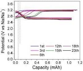
Although the effective positive electrode remains to be identified and developed, the galvanostatic charge/discharge curves of a Na-Cs ‖ NaI flow cell using graphite felt GFD 5.0 as the positive electrode has been evaluated (Figure 6). Note that the aqueous catholyte in this hybrid flow cell only contained 0.068 M NaI in order to minimize the charge/discharge time and complete a reasonable number of cycles in a timely manner. Furthermore, both charge and discharge were only conducted up to 1.0 mAh capacity, again to achieve a reasonable number of cycles in a timely manner. 1 mAh is ~13.7% of the theoretical capacity of the catholyte in this flow cell. Several interesting trends can be concluded from these charge/discharge curves. First, the starting open circuit voltage (OCV) of 3.04 V is very close to the theoretical value of the standard cell potential of the Na-Cs ‖ NaI cell (3.23 V) with the triiodide/iodide (I3−/I−) redox couple during charge/discharge as described by Equations (1) and (2) [46]. After the charge operation starts, the cell voltage increases gradually because of the gradually increased concentration of triiodide ions, as predicted by Nernst equation [46]:
where E is the potential of the triiodide/iodide redox reaction, E0 the standard potential, R the gas constant, T the absolute temperature, n the number of moles of electrons transferred, F the Faraday constant, and and are the activities of I3− and I−, respectively. Second, the charge and discharge curves are smooth, suggesting a stable system with behavior described well by Nernst equation. Third, the Coulombic efficiency is 100% and the voltaic efficiency is ~85% for the first 12 cycles, but increases to ~87% after 12 cycles because of the appearance of a new charge plateau at ~2.75 V. Together, the Coulombic efficiency and voltaic efficiency of the present cell setup lead to an energy efficiency ≥85%. Fourth, since the pH values of the NaI aqueous solution are near neutral (6.3–7.2), the practical oxygen evolution reaction (OER) and hydrogen evolution reaction (HER) will thus take place at the potentials of ~1.3 V and ~–0.75 V (vs. SHE) or ~4.0 V and ~2.0 V (vs. Na+/Na), respectively [49]. As the charge/discharge voltage window for the Na-Cs ‖ NaI hybrid flow battery is >2.5 V and <3.3 V, no OER and HER are expected to occur, thereby a stable system without electrochemical water splitting for the Na-Cs ‖ NaI hybrid flow batteries. Fifth, there is no noticeable increase in the potential gap between charge and discharge plateaus even after 23 cycles, indicating no obvious increase in the overpotential of the cell. The monitoring of the cell impedance also confirms this, suggesting the possibility of Na-Cs ‖ NaI hybrid flow batteries with long cycle life. Sixth, the flow cell displays small IR drop/increase when current changes during charge/discharge. This is consistent with the moderate impedance of the flow cell determined using EIS (Figure 5). Seventh, a new plateau at ~2.75 V appears gradually in the charge curve as the charge/discharge cycle increases beyond the 6th cycle. The appearance of this plateau improves the voltaic efficiency because the discharge plateau does not undergo similar alternation. At this stage the mechanism for this new plateau is not clear. Reference [50] has summarized various redox reactions that can occur in the iodine-iodide system. However, none of them can provide a reasonable explanation for the redox plateau at ~2.75 V observed in this study. Thus, we hypothesize that this interesting phenomenon is related to the evolution of the surface functionality of the positive electrode during cycles.
The final interesting conclusion from Figure 6b is that both charge and discharge curves shift downward gradually by ~0.1 V over 23 cycles. It is not clear at this stage what is responsible for this phenomenon and whether this trend will stop after a large number of cycles. One possible reason for this shift would be the evolution of the catalytic activity of the positive electrode, similar to the mechanism responsible for the gradual appearance of a new charge plateau at ~2.75 V. The downward shift is very mild so far, but how that goes at a large number of cycles needs further investigation. Another possible reason for the downward shift is the viscosity changes similar to that reported in the Li-I2 system [36,46]. The underlying mechanism for this downward shifting will be studied in the future to provide a stable and predictable energy storage system.
Before closing, it is worth of comparing the potential of HNFBs with the state-of-the-art VRBs. Assuming that a Na-Cs ‖ NaI hybrid flow battery is made of a Na90Cs10 anode and an aqueous NaI catholyte with a NaI concentration at 9 M (<12 M solubility reported in References [42,43]), then this HNFB has a theoretical specific energy of 256 Wh/kg and energy density of 508 Wh/L, both of which are more than 10 times the specific energy (15–25 Wh/kg) and energy density (20–33 Wh/L) of the state-of-the-art VRBs [13,14]. Further, the energy efficiency of the Na-Cs ‖ NaI hybrid flow battery is high (≥85%), comparable with VRBs (70–90%) [51]. However, before these great potentials can be fully exploited for practical applications, the catalytic activities of the positive electrodes need to be improved significantly, as revealed in this study. In addition, the ionic conductivity and conductance of the NaSICON membrane should be enhanced as well to allow high power applications. Finally, the mechanical durability of the NaSICON membrane is essential for safe operation of HNFBs. Although in this study no microcracking or fracture of NaSICON membranes was observed in several-month continuous operation, real-world grid-scale energy storage would require several-year operation, and thus this topic should be addressed in the future.
4. Conclusions
This study shows, for the first time, the feasibility of the Na-Cs ‖ NaI hybrid flow battery. The study of cyclic voltammetry reveals that the positive electrodes made of precious metals, carbonaceous materials, or Nb2O5- and WO3-decorated carbonaceous materials do not provide symmetric electrocatalytic activities for oxidation and reduction of the triiodide/iodide redox couple in aqueous solution. Graphite felt GFD 5.0 is the only exception to this general phenomenon, exhibiting symmetric electrocatalytic activities for the triiodide/iodide redox couple in aqueous solution but with relatively large overpotentials for both oxidation and reduction having the peak separation around 0.77 V. The EIS investigation of the Na-Cs‖NaI flow cell with graphite felt GFD 5.0 as the positive electrode indicates that Rct due to the charge transfer at the positive electrode/catholyte interface is significantly higher than Rb, Rgb and Rint, suggesting that the charge transfer at the positive electrode/catholyte interface is the rate-limiting step for charge/discharge of the Na-Cs‖NaI flow cell—a problem that needs to be solved for the rate capability of the Na-Cs‖NaI hybrid flow battery. Galvanostatic charge/discharge tests show that the Na-Cs ‖ NaI hybrid flow battery has the potential to achieve the following properties simultaneously: (i) an aqueous NaI catholyte with good cycle stability, (ii) a durable and low impedance NaSICON membrane for a large number of cycles, (iii) stable interfaces at both anode/membrane and cathode/membrane interfaces, (iv) a molten Na-Cs anode capable of repeated Na plating and stripping, and (v) a flow battery with high Coulombic efficiency, high voltaic efficiency, and high energy efficiency.
Author Contributions
C.L. has designed experiments with L.S., conducted experiments and analyzed all the results. L.S. has co-designed experiments with C.L. and written the article.
Funding
This research received no external funding.
Acknowledgments
The authors are grateful to the insightful discussion with Vincent Sprenkle at Pacific Northwest National Laboratory (PNNL). The financial support from Rowe Family Endowment Fund at Illinois Institute of Technology is also greatly appreciated.
Conflicts of Interest
The authors declare no conflicts of interest.
References
- Dunn, B.; Kamath, H.; Tarascon, J.-M. Electrical energy storage for the grid: A battery of choices. Science 2011, 334, 928–935. [Google Scholar] [CrossRef] [PubMed]
- Wang, W.; Luo, Q.; Li, B.; Wei, X.; Li, L.; Yang, Z. Recent progress in redox flow battery research and development. Adv. Funct. Mater. 2013, 23, 970–986. [Google Scholar] [CrossRef]
- Soloveichik, G.L. Flow batteries: Current status and trends. Chem. Rev. 2015, 115, 11533–11558. [Google Scholar] [CrossRef] [PubMed]
- De Leon, C.P.; Frias-Ferrer, A.; Gonzalez-Garcia, J.; Szanto, D.A.; Walsh, F.C. Redox flow cells for energy conversion. J. Power Sources 2006, 160, 716–732. [Google Scholar] [CrossRef] [Green Version]
- Duduta, M.; Ho, B.; Wood, V.C.; Limthongkul, P.; Brunini, V.E.; Carter, W.C.; Chiang, Y.-M. Semi-solid lithium rechargeable flow battery. Adv. Energy Mater. 2011, 1, 511–516. [Google Scholar] [CrossRef]
- Xi, J.; Wu, Z.; Qiu, X.; Chen, L. Nafion/SiO2 hybrid membrane for vanadium redox flow battery. J. Power Sources 2007, 166, 531–536. [Google Scholar] [CrossRef]
- Chen, D.; Wang, S.; Xiao, M.; Meng, Y. Preparation and properties of sulfonated poly(fluorenyl ether ketone) membrane for vanadium redox flow battery application. J. Power Sources 2010, 195, 2089–2095. [Google Scholar] [CrossRef]
- Luo, Q.; Zhang, H.; Chen, J.; You, D.; Sun, C.; Zhang, Y. Preparation and characterization of Nafion/SPEEK layered composite membrane and its application in vanadium redox flow battery. J. Membr. Sci. 2008, 325, 553–558. [Google Scholar] [CrossRef]
- Zeng, J.; Jiang, C.; Wang, Y.; Chen, J.; Zhu, S.; Zhao, B.; Wang, R. Studies on polypyrrole modified nafion membrane for vanadium redox flow battery. Electrochem. Commun. 2008, 10, 372–375. [Google Scholar] [CrossRef]
- Mai, Z.; Zhang, H.; Li, X.; Xiao, S.; Zhang, H. Nafion/polyvinylidene fluoride blend membranes with improved ion selectivity for vanadium redox flow battery application. J. Power Sources 2011, 196, 5737–5741. [Google Scholar] [CrossRef]
- Sun, J.; Li, X.; Xi, X.; Lai, Q.; Liu, T.; Zhang, H. The transfer behavior of different ions across anion and cation exchange membranes under vanadium flow battery medium. J. Power Sources 2014, 271, 1–7. [Google Scholar] [CrossRef]
- Viswanathan, V.; Crawford, A.; Stephenson, D.; Kim, S.; Wang, W.; Li, B.; Coffey, G.; Thomsen, E.; Graff, G.; Balducci, P.; et al. Cost and performance model for redox flow batteries. J. Power Sources 2014, 247, 1040–1051. [Google Scholar] [CrossRef]
- Li, L.; Kim, S.; Wang, W.; Vijayakamar, M.; Nie, Z.; Chen, B.; Zhang, J.; Xia, G.; Hu, J.; Graff, G.; et al. A stable vanadium redox-flow battery with high energy density for large-scale energy storage. Adv. Energy Mater. 2011, 1, 394–400. [Google Scholar] [CrossRef]
- Zhao, Y.; Ding, Y.; Song, J.; Peng, L.; Goodenough, J.B.; Yu, G. A reversible Br2/Br redox couple in the aqueous phase as a high-performance catholyte for alkali-ion batteries. Energy Environ. Sci. 2014, 7, 1990. [Google Scholar] [CrossRef]
- Bartolozzi, M. Development of redox flow batteries. A historical bibliography. J. Power Sources 1989, 27, 219–234. [Google Scholar] [CrossRef]
- Morrissey, P. Regenesys: A new energy storage technology. Int. J. Ambient Energy 2000, 21, 213–220. [Google Scholar] [CrossRef]
- Price, A.; Bartley, S.; Male, S.; Cooley, G. A novel approach to utility scale energy storage. Power Eng. J. 1999, 13, 122–129. [Google Scholar] [CrossRef]
- Gattrell, M.; Park, J.; MacDougall, B.; Apte, J.; McCarthy, S.; Wu, C.W. Study of the mechanism of the vanadium 4+/5+ redox reaction in acidic solutions. J. Electrochem. Soc. 2004, 151, A123–A130. [Google Scholar] [CrossRef]
- Skyllas-Kazacos, M. Novel vanadium chloride/polyhalide redox flow battery. J. Power Sources 2003, 124, 299–302. [Google Scholar] [CrossRef]
- Oriji, G.; Katayama, Y.; Miura, T. Investigation on V(IV)/V(V) species in a vanadium redox flow battery. Electrochim. Acta 2004, 49, 3091–3095. [Google Scholar] [CrossRef]
- Xi, X.; Li, X.; Wang, C.; Lai, Q.; Cheng, Y.; Zhou, W.; Ding, C.; Zhang, H. Impact of proton concentration on equilibrium potential and polarization of vanadium flow batteries. Chempluschem 2015, 80, 382–389. [Google Scholar] [CrossRef]
- Wang, G.; Chen, J.; Wang, X.; Tian, J.; Kang, H.; Zhu, X.; Zhang, Y.; Liu, X.; Wang, R. Study on stabilities and electrochemical behavior of V(V) electrolyte with acid additives for vanadium redox flow battery. J. Energy Chem. 2014, 23, 73–81. [Google Scholar] [CrossRef]
- Roe, S.; Menictas, C.; Skyllas-Kazacos, M. A high energy density vanadium redox flow battery with 3 M vanadium electrolyte. J. Electrochem. Soc. 2016, 163, A5023–A5028. [Google Scholar] [CrossRef]
- Liu, Q.; Sleightholme, A.E.S.; Shinkle, A.A.; Li, Y.; Thompson, L.T. Non-aqueous vanadium acetylacetonate electrolyte for redox flow batteries. Electrochem. Commun. 2009, 11, 2312–2315. [Google Scholar] [CrossRef]
- Wang, W.; Xu, W.; Cosimbescu, L.; Choi, D.; Li, L.; Yang, Z. Anthraquinone with tailored structure for a nonaqueous metal-organic redox flow battery. Chem. Commun. 2012, 48, 6669–6671. [Google Scholar] [CrossRef] [PubMed]
- Chakrabarti, M.H.; Dryfe, R.A.W.; Roberts, E.P.L. Evaluation of electrolytes for redox flow battery applications. Electrochim. Acta 2007, 52, 2189–2195. [Google Scholar] [CrossRef]
- Zhang, D.; Lan, H.; Li, Y. The application of a non-aqueous bis(acetylacetone)ethylenediamine cobalt electrolyte in redox flow battery. J. Power Sources 2012, 217, 199–203. [Google Scholar] [CrossRef]
- Li, Z.; Li, S.; Liu, S.; Huang, K.; Fang, D.; Wang, F.; Peng, S. Electrochemical properties of an all-organic redox flow battery using 2,2,6,6-tetramethyl-1-piperidinyloxy and N-methylphthalimide. Electrochem. Solid-State Lett. 2011, 14, 171–173. [Google Scholar] [CrossRef]
- Shinkle, A.A.; Sleightholme, A.E.S.; Griffith, L.D.; Thompson, L.T.; Monroe, C.W. Degradation mechanisms in the non-aqueous vanadium acetylacetonate redox flow battery. J. Power Sources 2012, 206, 490–496. [Google Scholar] [CrossRef]
- Shinkle, A.A.; Pomaville, T.J.; Sleightholme, A.E.S.; Thompson, L.T.; Monroe, C.W. Solvents and supporting electrolytes for vanadium acetylacetonate flow batteries. J. Power Sources 2014, 248, 1299–1305. [Google Scholar] [CrossRef]
- Bae, C.H.; Roberts, E.P.L.; Dryfe, R.A.W. Chromium redox couples for application to redox flow batteries. Electrochim. Acta 2002, 48, 279–287. [Google Scholar] [CrossRef]
- Sleightholme, A.E.S.; Shinkle, A.A.; Liu, Q.; Li, Y.; Monroe, C.W.; Thompson, L.T. Non-aqueous manganese acetylacetonate electrolyte for redox flow batteries. J. Power Sources 2011, 196, 5742–5745. [Google Scholar] [CrossRef]
- Herr, T.; Fischer, P.; Tübke, J.; Pinkwart, K.; Elsner, P. Increasing the energy density of the non-aqueous vanadium redox flow battery with the acetonitrile-1,3-dioxolane–dimethyl sulfoxide solvent mixture. J. Power Sources 2014, 265, 317–324. [Google Scholar] [CrossRef]
- Riechel, T.L. Electrochemical studies of vanadium(III) and vanadium(IV) acetylacetonate complexes in dimethylsulfoxide. Inorg. Chem. 1981, 20, 1974–1978. [Google Scholar]
- Herr, T.; Noack, J.; Fischer, P.; Tübke, J. 1,3-Dioxolane, tetrahydrofuran, acetylacetone and dimethyl sulfoxide as solvents for non-aqueous vanadium acetylacetonate redox-flow-batteries. Electrochim. Acta 2013, 113, 127–133. [Google Scholar] [CrossRef]
- Zhao, Y.; Byon, H.R. High-performance lithium-iodine flow battery. Adv. Energy Mater. 2013, 3, 1630–1635. [Google Scholar] [CrossRef]
- Wei, X.; Xu, W.; Vijayakumar, M.; Cosimbescu, L.; Liu, T.; Sprenkle, V.; Wang, W. TEMPO-based catholyte for high-energy density nonaqueous redox flow batteries. Adv. Mater. 2014, 26, 7649–7653. [Google Scholar] [CrossRef] [PubMed]
- Fan, F.Y.; Woodford, W.H.; Li, Z.; Baram, N.; Smith, K.C.; Helal, A.; McKinley, G.H.; Carter, W.C.; Chiang, Y.-M. Polysulfide flow batteries enabled by percolating nanoscale conductor networks. Nano Lett. 2014, 14, 2210–2218. [Google Scholar] [CrossRef] [PubMed]
- Shamie, J.S.; Liu, C.; Shaw, L.; Sprenkle, V.L. Room temperature, hybrid sodium-based flow batteries with multi-electron transfer redox reactions. Sci. Rep. 2015, 5, 11215. [Google Scholar] [CrossRef] [PubMed]
- Liu, C.; Shamie, J.S.; Shaw, L.; Sprenkle, V.L. An ambient temperature molten sodium-vanadium battery with aqueous flowing catholyte. ACS Appl. Mater. Interfaces 2016, 8, 1545–1552. [Google Scholar] [CrossRef] [PubMed]
- Shamie, J.S.; Liu, C.; Shaw, L.; Sprenkle, V.L. New mechanism for the reduction of vanadyl acetylacetonate to vanadium acetylacetonate for room temperature flow batteries. ChemSusChem 2017, 10, 533–540. [Google Scholar] [CrossRef] [PubMed]
- Seidell, A. Solubiities of Inorganic and Organic Substances, 2nd ed.; D. Van Nostrand Company: New York, NY, USA, 1919. [Google Scholar]
- Dean, J.A. Lange’s Chemistry Handbook, 14th ed.; McGraw-Hill Professional Publishing: New York, NY, USA, 1992. [Google Scholar]
- Yao, C.; Zhang, H.; Liu, T.; Li, X.; Liu, Z. Carbon paper coated with supported tungsten trioxide as novel electrode for all-vanadium flow battery. J. Power Sources 2012, 218, 455–461. [Google Scholar] [CrossRef]
- Li, B.; Gu, M.; Nie, Z.; Wei, Z.; Wang, C.; Sprenkle, V.; Wang, W. Nanorod niobium oxide as powerful catalysts for an all vanadium redox flow battery. Nano Lett. 2014, 14, 158–165. [Google Scholar] [CrossRef] [PubMed]
- Zhao, Y.; Wang, L.; Byon, H.R. High performance rechargeable lithium-iodine batteries using triiodide/iodide redox couples in an aqueous cathode. Nat. Commun. 2013, 4, 1896. [Google Scholar] [CrossRef] [PubMed]
- Zhao, M.; Crooks, R.M. Homogeneous hydrogenation catalysis with monodisperse, dendrimer-encapsulated Pd and Pt nanoparticle. Angew. Chem. Int. Ed. 1999, 38, 364–366. [Google Scholar] [CrossRef]
- Kung, H.H.; Kung, M.C.; Costello, C.K. Supported Au catalysts for low temperature CO oxidation. J. Catal. 2003, 216, 425–432. [Google Scholar] [CrossRef]
- Chen, L.; Guo, Z.; Xia, Y.; Wang, Y. High-voltage aqueous battery approaching 3 V using an acidic–alkaline double electrolyte. Chem. Commun. 2013, 49, 2204–2206. [Google Scholar] [CrossRef] [PubMed]
- Boschloo, G.; Hagfeldt, A. Characteristics of the iodide/triiodide redox mediator in dye-sensitized solar cells. Acc. Chem. Res. 2009, 42, 1819–1826. [Google Scholar] [CrossRef] [PubMed]
- Kear, G.; Shah, A.A.; Walsh, F.C. Development of the all-vanadium redox flow battery for energy storage: A review of technological, financial and policy aspects. Int. J. Energy Res. 2012, 36, 1105–1120. [Google Scholar] [CrossRef]
Figure 1.
Schematic of a hybrid Na-based flow battery (HNFB) with a floating Na-Cs anode on the Na-ion exchange membrane and a flowing catholyte, operated at room temperature [39,40,41].

Figure 2.
Cyclic voltammograms of 0.01 M I2–1.5 M NaI catholyte on (a) Au and (b) Pt. Ag/AgCl and Pt wire were used as reference and counter electrodes, respectively. The scan rates are indicated in each figure.
Figure 2.
Cyclic voltammograms of 0.01 M I2–1.5 M NaI catholyte on (a) Au and (b) Pt. Ag/AgCl and Pt wire were used as reference and counter electrodes, respectively. The scan rates are indicated in each figure.

Figure 3.
Cyclic voltammograms (CVs) of 0.01 M I2–1.5 M NaI catholyte on various carbonaceous electrodes: (a) Glassy carbon (GC) foam and carbon paper electrode, (b) graphite felt GFD4.6 and GFD5.0, and (c) Au and activated carbon (AC). Ag/AgCl and Pt wire were used as reference and counter electrodes, respectively. Both graphite felts were annealed in air at 550 °C for 5 h before testing. The AC electrode was prepared by drop-casting AC nanoparticle slurry on an Au electrode and then drying it under infrared light. The scan rates are indicated in each figure.

Figure 4.
Cyclic voltammograms of 0.01 M I2–1.5 M NaI catholyte on (a) graphite felt GFD4.6 with WO3 deposit and (b) graphite felt GFD4.6 with Nb2O5 deposit. Ag/AgCl and Pt wire were used as reference and counter electrodes, respectively. The scan rates are indicated in each figure.
Figure 4.
Cyclic voltammograms of 0.01 M I2–1.5 M NaI catholyte on (a) graphite felt GFD4.6 with WO3 deposit and (b) graphite felt GFD4.6 with Nb2O5 deposit. Ag/AgCl and Pt wire were used as reference and counter electrodes, respectively. The scan rates are indicated in each figure.

Figure 5.
(a) The Nyquist plots of the NaSICON membrane and Na-Cs‖NaI flow cell with apparent area of ~4 cm2, and (b) the equivalent circuits for the simulation of the impedance spectra in (a). The Nyquist plot of the NASICON membrane was obtained from a NaClO4 (1 M aq.) | NaSICON | NaClO4 (1 M aq.) symmetric cell, whereas the corresponding plot of the flow cell was from Na37Cs63 | NaSICON | 0.25M NaI aqueous solution, measured at the open-circuit voltage of the cell in the frequency range of 100k–0.1 Hz with ac signal amplitude of 10 mV. For the flow cell, graphite felt GFD5.0 was used as the electrode and current collector of the cathode, whereas stainless steel casing was used as the current collector of the anode. Similar equivalent circuits (1) and (2) have been used previously to simulate the impedance spectra of a Li-ion conducting membrane and a Li | solid electrolyte | LiBr aqueous solution cell, respectively [14].

Figure 6.
(a) Galvanostatic charge/discharge curves of a Na-Cs ‖ NaI flow cell with the cycle number indicated, and (b) zoom-in view of (a). The positive electrode is graphite felt GFD5.0 and catholyte is 0.068 M NaI aqueous solution, whereas the anode is made up of a Na37Cs63 slurry. The discharge was under 0.05 mA current for 1 h as the activation step and then 0.1 mA current up to 1.0 mAh capacity, whereas the charging cycle was started at 0.05 and 0.10 mA for 1 h each and then at 0.15 mA until reaching 1.0 mAh for the first 10 cycles. In the subsequent cycles the 0.10 mA step was set to 20 min while the other steps were kept the same in the charge segment. The test was run in a dark box.

© 2018 by the authors. Licensee MDPI, Basel, Switzerland. This article is an open access article distributed under the terms and conditions of the Creative Commons Attribution (CC BY) license (http://creativecommons.org/licenses/by/4.0/).
Share and Cite
MDPI and ACS Style
Liu, C.; Shaw, L. A High Capacity, Room Temperature, Hybrid Flow Battery Consisting of Liquid Na-Cs Anode and Aqueous NaI Catholyte. Batteries 2018, 4, 60. https://doi.org/10.3390/batteries4040060
AMA Style
Liu C, Shaw L. A High Capacity, Room Temperature, Hybrid Flow Battery Consisting of Liquid Na-Cs Anode and Aqueous NaI Catholyte. Batteries. 2018; 4(4):60. https://doi.org/10.3390/batteries4040060
Chicago/Turabian StyleLiu, Caihong, and Leon Shaw. 2018. "A High Capacity, Room Temperature, Hybrid Flow Battery Consisting of Liquid Na-Cs Anode and Aqueous NaI Catholyte" Batteries 4, no. 4: 60. https://doi.org/10.3390/batteries4040060
Note that from the first issue of 2016, this journal uses article numbers instead of page numbers. See further details here.