Electrochemical Performance and Thermal Stability of Iron Oxyfluoride (FeOF) for Sodium-Ion Batteries
by
 ,
,
Ayuko Kitajou
1,* ,
,
Liwei Zhao
2,
Rintaro Nagano
3,
Atsushi Inoishi
4,
Eiji Kobayashi
2 and
Shigeto Okada
2,*
1
Organization for Research Initiatives, Yamaguchi University, Yamaguchi 755-8611, Japan
2
Institute for Materials Chemistry and Engineering, Kyushu University, Fukuoka 816-8580, Japan
3
Interdisciplinary Graduate School of Engineering Sciences, Kyushu University, Fukuoka 816-8580, Japan
4
Department of Applied Chemistry, Faculty of Engineering, Kyushu University, Fukuoka 819-0395, Japan
*
Authors to whom correspondence should be addressed.
Batteries 2018, 4(4), 68; https://doi.org/10.3390/batteries4040068
Submission received: 18 July 2018
/
Revised: 7 November 2018
/
Accepted: 27 November 2018
/
Published: 7 December 2018
(This article belongs to the Special Issue Sodium-Ion Battery: Materials and Devices)
Abstract
:Self-synthesized rutile iron oxyfluoride (FeOF) was studied as a cathode material for Na-ion batteries. The highly crystalline FeOF provided an initial discharge capacity of 246 mAh g−1 in a voltage range of 1.0–4.0 V, followed by 88% of capacity retention after 20 cycles. This discharge-charge reaction of FeOF between 0.8 and 4.0 V are advanced by the Fe2+/Fe3+ redox reaction. That is, no conversion reaction was involved in the application of FeOF as a cathode material for Na-ion batteries because of the low potential of Na-insertion. In addition, the structure change of FeOF from rutile to cubic during Na ion insertion, which was similar to that in Li-ion batteries. No remarkable HF release was detected even up to 700 °C, indicating a low toxic risk of the FeOF cathode. The thermal properties of sodiated and desodiated FeOF electrodes in the associated electrolyte were investigated by DSC (Differential scanning calorimetry) up to 500 °C. Sodiated FeOF electrodes showed larger exothermic heat generation than desodiated ones, especially at a temperature higher than 380 °C. Finally, the thermal stability of FeOF cathodes in the associated Li- and Na-ion battery electrolytes was quantitatively compared with variations of the electrode/electrolyte ratio.
1. Introduction
Na-ion batteries are an attractive candidate for next-generation secondary batteries because of the low cost and the abundance of sodium. Numerous cathode active materials have been proposed for Na-ion batteries. Among them, conversion-type cathode materials, such as FeS2 [1], are of special interest to battery researchers for the use in the fabrication of large capacity Na-ion batteries due to their ability to utilize the entire valence change between the ionic and metallic state of the cation in the active material [2]. In particular, the iron-based versions are promising by virtue of their low cost, large theoretical capacities, and low environmental impact.
Three ferric conversion-type active materials, Fe2O3, FeF3, and iron oxyfluoride (FeOF), have been investigated as potential electrode materials for Li-ion batteries. Among them, Fe2O3 generates the largest theoretical capacity but the lowest operating potential of 0.8 V versus Li metal [3], and thus, it would be applicable only as an anode material. In contrast, FeF3 gives the highest average voltage due to its highly ionic metal-ligand bonds, however, its electronic conductivity is very poor due to the large energy gap [4]. Thus, FeOF is the middle choice, with a theoretical capacity and operating potential intermediate between those of Fe2O3 and FeF3, but with the largest energy density of the three materials [5,6]. Moreover, owing to the introduction of more covalent M-O bonds into the highly ionic fluoride structure and the resulting improvement in electronic conductivity, iron oxyfluoride exhibits much better electrochemical performance than iron fluoride. By using a roll-quenching method, a highly crystalline FeOF was successfully synthesized in our laboratory [7]. The obtained FeOF exhibits an excellent reversible capacity of 550 mAh g−1 versus Li metal, corresponding to 1.8 Li+ per FeOF molecule, and also shows a good cycling efficiency value of 70.9% between 1.3 V and 4.0 V.
As is well known, the fundamental principles of Na-ion batteries and Li-ion batteries are identical, because Na is located below Li in the periodic table and they share many similar chemical properties. Therefore, many of the new components for Na-ion batteries could be developed in the same manner as their counterparts for Li-ion batteries. In the case of conversion-type active materials, because of their special reaction mechanism, theoretically, the active materials for Li-ion batteries could be used directly for Na-ion batteries. Therefore, we previously investigated FeOF as a cathode material for Na-ion batteries [8]. Additionally, Zhu et al. [9] recently reported a wet-chemically synthesized FeOF nanorod as the cathode material for Na-ion batteries. A reversible capacity of 300 mAh g−1 was obtained after the first cycle between 1.0 V and 4.0 V. However, the details of the electrochemical discharge reaction between FeOF and Na have not yet been clarified.
Safety is one of the most important issues for the practical application and development of batteries. For any battery, a thermal balance between heat generation and heat dissipation in the cell is critical. In brief, the heat generation is directly proportional to the cell volume, while the heat dissipation is proportional to the cell surface area. In large-scale batteries, the thermal dissipation rate becomes much lower because of the reduced surface area. Therefore, the potential safety risk becomes a serious problem with the scaling-up of batteries, especially when the batteries are handled roughly or abused. Na-ion batteries have been the main batteries proposed for large-scale electric energy storage applications. Na-ion batteries have a working mechanism similar to that of Li-ion batteries, which are well known to risk thermal instability under severe conditions or rough handling. Moreover, sodium shows an even higher reactivity in air than in Li metal. For these reasons, a study on the thermal stability of Na-ion batteries is indispensable for their safe practical application.
In the present study, highly crystalline FeOF synthesized by a quick roll-quenching method was applied as the cathode material for Na-ion batteries. The electrochemical properties were studied against Na metal in different voltage ranges. In addition, to determine the discharge-charge reaction mechanism of FeOF, the crystal structure changes of FeOF pellets during the electrochemical cycling were investigated by synchrotron-based X-ray absorption near edge structure (XANES) and X-ray diffraction (XRD) analyses. Then, by using a TG-DSC and a TG/DTA-MS system, the thermal characteristics of FeOF cathodes in Na-ion batteries were investigated in detail. Finally, the thermal stabilities of FeOF cathodes in Li- and Na-ion batteries were compared.
2. Results and Discussion
From the XRD profile, the obtained FeOF could be indexed to a tetragonal structure of the space group P42/mnm, in agreement with our previous report [7], although a small amount of the starting material, FeF3 and Fe2O3, remained as an impurity. The electrochemical performance of the FeOF electrode was investigated against Na metal in half-cells at a rate of 10 mA g−1. Figure 1a shows the typical charge/discharge profiles of the first cycle. The discharge cut-off potentials were set to 0.8 and 0.05 V, respectively, while the charge cut-off potentials were set at 4.0 V. As a reference, the first charge/discharge curves of the FeOF/Li half-cell in a voltage range of 0.7–4.0 V (versus Li metal) were also presented. In the case of the FeOF/Li cell, the voltage gradually decreased through inflection points at approximately 2.6, 1.8, and 0.9 V during the initial discharge process [7]. However, in the case of the FeOF/Na cell, no clear inflection point was observed in the discharge curves, and the discharge voltage was circa 1 V lower than that for the FeOF/Li cell. With the gradual decrease of voltage to 0.05 V, a first discharge capacity of 600 mAh g−1 was obtained, corresponding to a 2 Na+ reaction with FeOF. Clearly, a complete conversion reaction of FeOF (FeOF + 3Na ⇄ 3NaF + Fe) could not be achieved because of the low discharge voltage of FeOF/Na cells. It was also clear that FeOF cannot be used as a cathode material in this voltage range. When the discharge cut-off potential was raised to 0.8 V, an initial discharge capacity of 293 mAh g−1 was obtained, with an average voltage of 1.3 V. The calculated energy density was 380 Wh kg−1, a value comparable to that for alluaudite-type Na2Fe2(SO4)3, which has the highest Fe2+/Fe3+ redox potential at 3.8 V [10].
The cyclability of the FeOF/Na cell over various voltage ranges is shown in Figure 1b. Three different voltage ranges, 0.05–4.0 V, 0.8–4.0 V, and 1.0–4.0 V, were applied. In the voltage range of 0.05–4.0 V, the cell capacity drastically dropped after three cycles. After dissembling the cell, a large amount of the electrode was found to have peeled off from the current collector. The large volume changes during Na ion insertion/extraction clearly induced severe electrode exfoliation and consequential capacity fading. In a narrowed voltage range of 0.8–4.0 V, the cell cyclability was improved significantly. However, gradual capacity fading still existed, especially after 10 cycles. A cycling efficiency of 35% remained after 20 cycles. After the discharge cut-off was raised to 1.0 V, a satisfactory cyclability was obtained. The first discharge capacity down to 1.0 V was 240 mAh g−1, while a value of 210 mAh g−1 was obtained even after 20 cycles. The cycling efficiency of FeOF between 1.0 V and 4.0 V was determined to be 88%. In comparison, FeS2 between 0.8 V and 2.6 V [11] and FeF3 between 1.5 V and 4.0 V [12] exhibited 40% and 60% cycling efficiencies, respectively. In the case of a deeper cycle between 0.8 V and 4.0 V, the discharge capacity was 100 mAh g−1 after 20 cycles. These results suggest that the structure of FeOF was drastically changed at lower voltages, especially below 1.0 V.
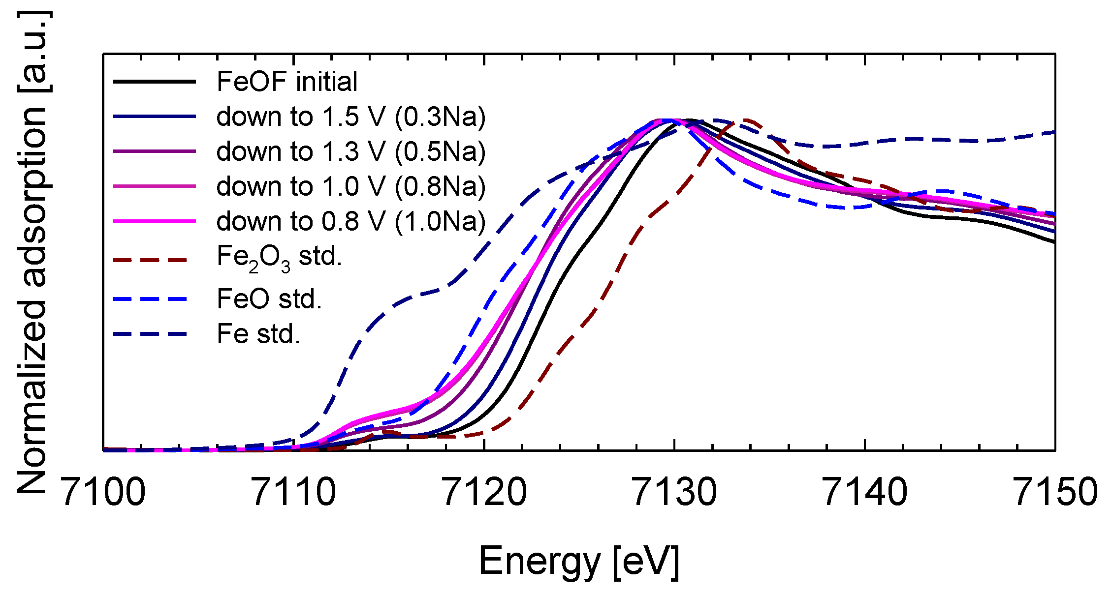
Figure 2 shows the XANES spectra of the initial FeOF cathode pellet and the discharged pellets cycled down to 1.5, 1.3, 1.0, and 0.8 V, which corresponded to 0.3, 0.5, 0.8, and 1.0 Na insertion, respectively, based on the discharge capacities. The XANES spectra of FeO, Fe2O3, and metallic iron are also provided as references. The Fe K-edge position evidently shifted to 7112 eV from 7113 eV following the discharge reaction down to 0.8 V from the initial state. This result indicates that the oxidation state of iron changed during the insertion reaction of Fe3+ to Fe2+ down to 0.8 V. That is, the conversion reaction was not included in the discharge process down to 0.8 V. In addition, the small pre-edge feature near 7112 eV, which corresponds to 1s → 3d transitions for the dipole forbidden in octahedral symmetry, did not change depending on the sodium content per FeOF. Therefore, this result suggested that the structure around Fe atoms maintained the octahedral symmetry until discharge reaction corresponding to ca. 1 Na per FeOF.
Figure 3 compares the XRD patterns for the initial FeOF cathode with those for materials discharged down to 1.3 V (0.5 Na-insertion), discharged down to 0.8 V (1 Na-insertion), and charged up to 4.0 V after 1 Na discharge, respectively. For reference, the XRD spectrum of a lithiated FeOF cathode obtained by discharging a FeOF/Li half-cell down to 1.8 V (equivalent to electrochemical synthesis of a LiFeOF phase) is also shown in this figure. The characteristic peaks of the FeOF crystal, especially the peak (110) at 27°, decreased when the electrode was discharged to 1.3 V, and then 0.8 V. At the same time, two new peaks at 40° and 58° appeared, became dominant, and increased. It was noted that the FeOF cathode under 1 Li insertion (LiFeOF) showed an XRD profile similar to that in Figure 3, although the two peaks showed a 10° shift. This leftward shift of the characteristic peaks might be attributable to the difference in ionic radius between Na+ and Li+, because sodium ions are nearly 25% larger than lithium ions. On the other hand, this result also suggested that the Na+ insertion induced a structural transition of the cathode from rutile-type FeOF to cubic-type NaxFeOF (0 < x < 1), just as in the case of Li+ insertion [6,7]. However, some diffraction peaks in the discharge state down to 0.8 V could be confirmed in addition to the diffraction peaks of cubic-type NaxFeOF. These diffraction peaks could be indexed as PTFE binder (the peak at 18°) and Fe2O3. The redox voltage of Fe3+/Fe2+ in Fe2O3/Li half-cell was 1.8 V, and this redox voltage in Fe2O3/Na half-cell was lower than that of the Fe2O3/Li half-cell. Therefore, the electrochemical reaction between Fe2O3 and Na+ did not proceed down to 0.8 V in the discharge process. Figure 3 (4) shows the XRD profile of the FeOF cathode upon recharging to 4.0 V after being discharged down to 0.8 V. The characteristic peaks (110), (101), and (211) of rutile-type FeOF could still be identified, although the intensities became much lower than the initial ones. This indicated a reversible extraction of Na+ from the FeOF pellet. However, the significantly decreased peak intensities also suggested a transformation of amorphous or nanocrystal FeOF during the charge process. Based on the results of the XANES and XRD analyses, a reversible insertion/extraction of Na+ into the FeOF cathode could be confirmed, and could be described by the following reactions:
Na+ + e− + FeOF (Rutile) → NaFeOF (Cubic) ⇄ Na+ + e− + FeOF (Amorphous or nanocrystal).
FeOF has been shown to have no higher risk of hypertoxic HF gas release than other fluorine-free electrodes in Li-ion batteries [13]. Nonetheless, because it is a fluorine-containing active material, its toxicity in Na-ion batteries must still be investigated. During electrochemical pretreatment, FeOF cathodes were sodiated at 0.8 or 1.0 V, and then desodiated at 4.0 V. A TG-MS analysis was performed on the cycled FeOF cathodes under operating conditions identical to those for the FeOF/Li samples. According to the MS spectra, all sodiated and desodiated FeOF cathodes showed slight HF evolution at temperatures higher than 500~600 °C, while the signals were even lower than that from FeOF/Li samples. Clearly, FeOF did not present a risk of toxicity in Na-ion batteries, and in fact, was even safer than in Li-ion batteries. On the other hand, the sodiated FeOF cathodes showed less HF evolution, with a 50 °C higher onset temperature than the desodiated ones. This indicated that NaFeOF might be more thermally stable than FeOF, as in the case of LiFeOF [13].
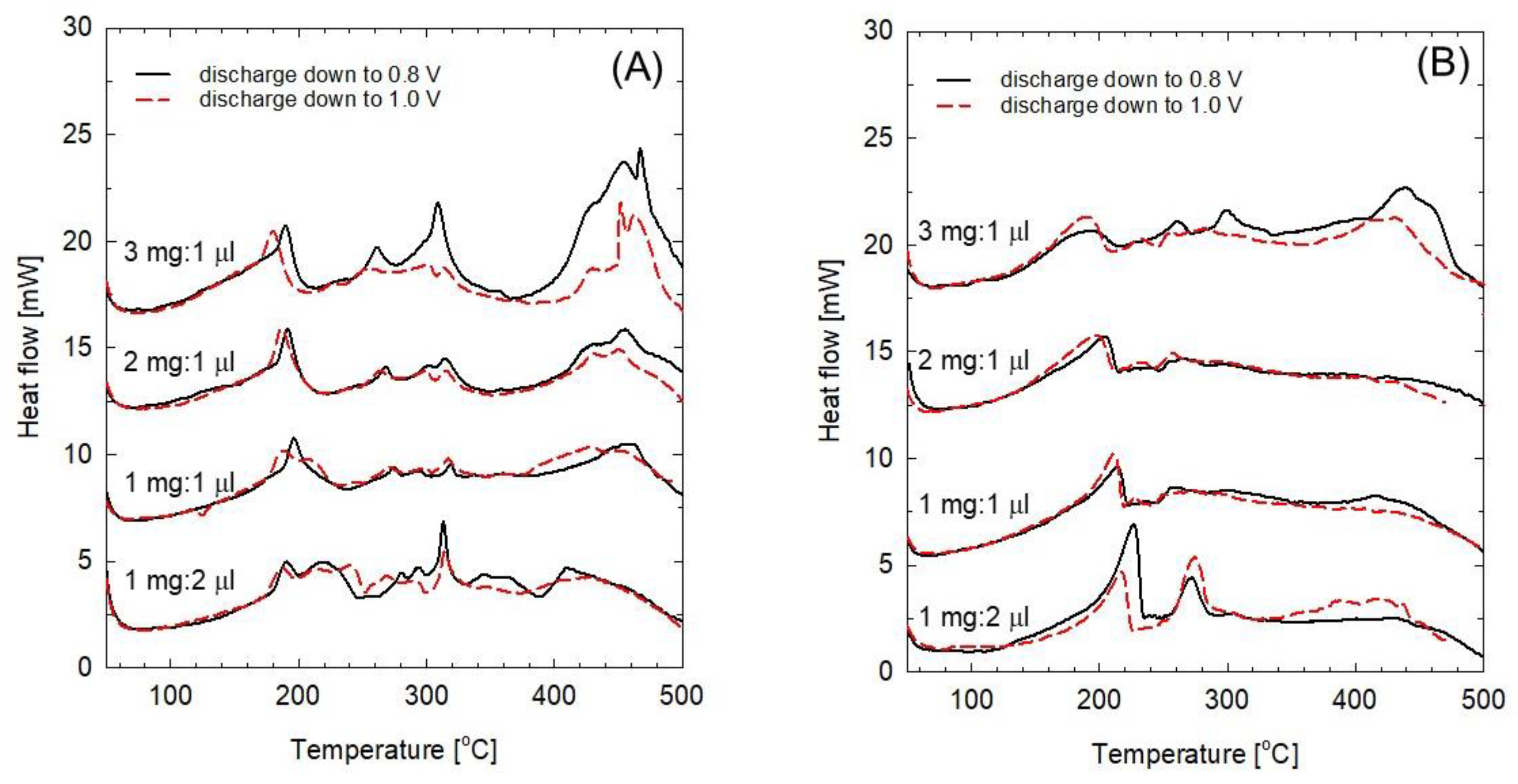
The thermal behavior in the associated electrolyte is one of the most important thermal characteristics of an electrode material. Therefore, a DSC analysis of a mixture of the FeOF cathode and associated electrolyte was carried out to evaluate the thermal stability of the FeOF cathode in Na-ion batteries. Figure 4 shows the DSC curves of the mixtures of the cycled FeOF cathode and the electrolyte at different electrode/electrolyte ratios; the curves in Figure 4A were obtained with sodiated FeOF, and the curves in Figure 4B were obtained with desodiated FeOF. Both electrodes were investigated with first cycling in the potential ranges of 0.8–4.0 and 1.0–4.0 V. The ratio between electrode and electrolyte was controlled to be 3 mg/L μL, 2 mg/L μL, 1 mg/L μL, and 1 mg/2 μL, respectively. Briefly, both sodiated and desodiated FeOF cathodes showed low exothermic onset temperature of about 100 °C, and continued with exothermic heat generation in a wide temperature range up to 500 °C. In the case of the sodiated FeOF, the exothermic heat generation in the temperature ranges of 220–380 °C and 380–500 °C clearly increased with an increasing amount of cathode in the mixture. Moreover, the exothermic peak obtained when the cathodes were discharged to 0.8 V was much larger than that obtained when the cathodes were discharged to 1.0 V. This difference was attributed to the insertion of a larger number of Na ions at a lower discharge cut-off potential of 0.8 V. On the other hand, the inserted Na ions showed no significant effect on the thermal properties of the mixture at temperatures lower than 200 °C, as the DSC curves obtained with cathodes under different discharge cut-off potentials were quite similar to each other and the increasing amount of cathode changed the DSC curves only slightly. Compared with the sodiated ones, the desodiated FeOF cathodes showed better thermal stability in the electrolyte as expected, including less heat generation and narrower heat distribution. However, the exothermic onset temperature was very close to that of the sodiated cathodes. In addition, fresh FeOF cathodes gave out heat at low temperature in the associated 1 mol dm−3 NaClO4/PC electrolyte, while no similar reaction was found when FeOF was heated together with 1 mol dm−3 LiPF6/EC-DMC electrolyte [13]. This phenomenon indicated that FeOF might be unstable in /PC solutions.
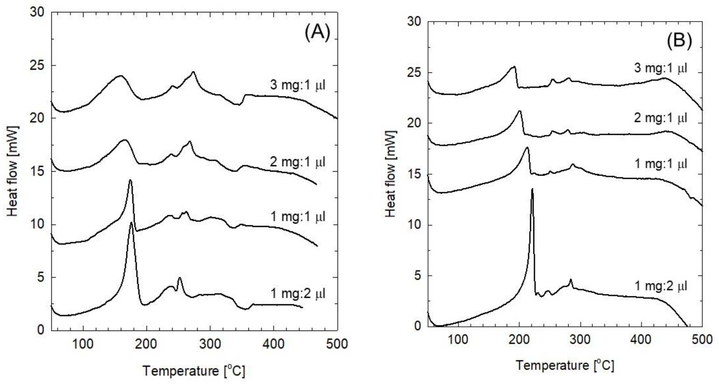
To compare the thermal stability of FeOF as a cathode active material for Li- and Na-ion batteries, the same FeOF cathode was cycled in 1 mol dm−3 LiClO4/PC electrolyte, followed by a DSC analysis as above. During cycling, the discharge capacity was controlled at 300 mAh g−1, while the charge cut-off potential was set at 4.0 V. Figure 5 shows the DSC curves of the mixtures of the cycled FeOF cathodes and the associated LiClO4/PC electrolyte. Unlike that in the 1 mol dm−3 LiPF6/EC-DMC solution [13], both sodiated and desodiated FeOF cathodes started their exothermic heat distribution from a low temperature of 100 °C, which was very similar to the pattern observed for the Na-ion battery. Obviously, reactions between FeOF and perchlorate salts and/or PC solvent were responsible for the heat generation. On the other hand, the coexisting LiClO4/PC electrolyte, which was present in a much larger amount than the NaClO4/PC electrolyte, generated a much larger amount of heat from the mixture. This phenomenon was likely attributable to the different thermal stabilities of the electrolytes. Above all, the most important difference between these two kinds of systems was the disappearance of the exothermic heat in the temperature range between 380–500 °C when lithiated FeOF was heated up mixed with LiClO4/PC electrolyte, while increasing exothermic heat generation was observed along with the increase in the amount of inserted Na ions in the corresponding Na system. However, the mechanism underlying these associations is still under investigation.
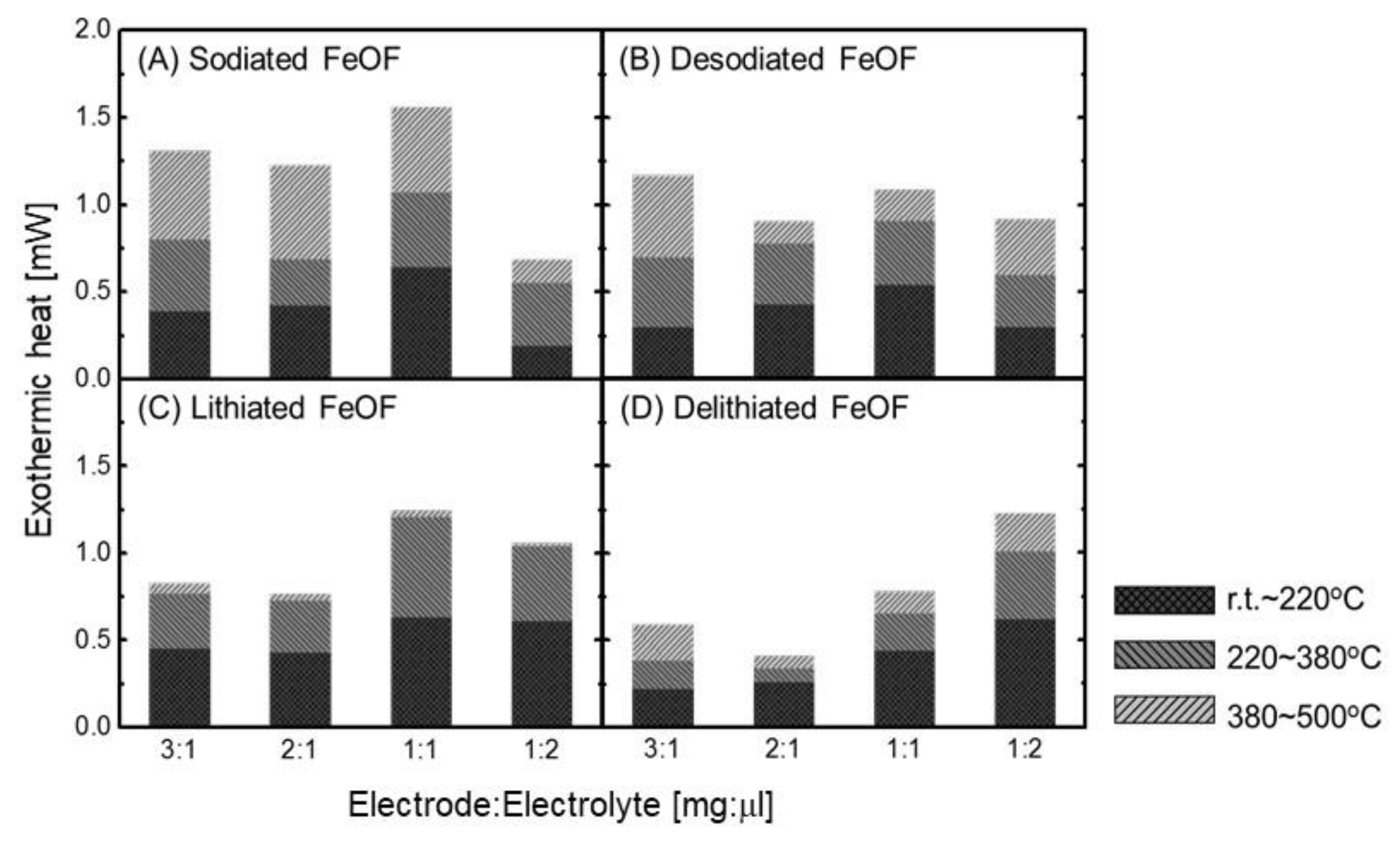
Using the DSC analysis results shown in Figure 4 and Figure 5, the thermal stability of FeOF cathodes in the associated Li- and Na-ion battery electrolytes was quantitatively compared with changes in the electrode/electrolyte ratio. The results are shown in Figure 6. For Na-ion batteries, the data obtained with the FeOF cathodes cycled in a voltage range of 1.0–4.0 V were selected for comparison. Each DSC curve was integrated in three temperature ranges, less than 220 °C, 220–380 °C, and 380–500 °C, respectively. The results of the comparison of Figure 6A,B and the comparison of Figure 6C,D were reasonable—namely, the FeOF cathode had better thermal stability in an ion-extracted state than in an ion-inserted state in both the Li- and Na-ion batteries. On the other hand, the comparisons of Figure 6A,C and of Figure 6B,D revealed that the FeOF cathode generated more heat in Na-ion batteries than in Li-ion batteries, irrespective of whether it was in an ion-inserted or ion-extracted state. Naturally, these conclusions were reached at an electrode/electrolyte ratio larger than 1 mg/L μL. When the mixture contained an overabundance of electrolyte, its thermal behavior was mainly controlled by the electrolyte instead of the electrode. It was also noted that the effects of the inserted Li and Na ions on the thermal properties of FeOF cathodes were different. The inserted Na ions induced large exothermic heat generation in a temperature range of 380–500 °C, while negligible exothermic heat was induced by the insertion of Li ions. In general, FeOF showed lower thermal risk in Li-ion batteries than in Na-ion batteries. However, it should be pointed out that heat generation is not the only relevant parameter when judging the thermal risk of a battery. The rate of heat generation must also be taken into consideration. For example, delithiated FeOF in the LiClO4/PC electrolyte was rather dangerous due to the rapidity of the heat generation.
3. Materials and Methods
FeOF was synthesized from a stoichiometric mixture of FeF3 (Soekawa Chemical, Saga, Japan) and Fe2O3 (Sigma-Aldrich, St. Louis, MS, USA) in a roll-quenching machine (Harddays Co., Newcastle, UK) according to a previously reported procedure [7]. The characterization of the obtained flake-like FeOF was carried out with an X-ray powder diffractometer (50 kV, 300 mA, Cu Ka, Rigaku TTRIII; Tokyo, Japan) to ensure the purity of the product. The obtained FeOF was dry ball-milled under Ar with acetylene black (AB) (Denka Co. Ltd., Tokyo, Japan) in a ratio of 70:25 wt.%, and the remainder was supplied by mixing it with a binder. Both sheet-type and pellet-type electrodes were prepared for different measurements. For electrochemical performance measurements and thermal stability analysis, sheet-type electrodes were prepared by mixing FeOF/C with 5 wt.% poly (acrylic acid) (WAKO; molecular weight: 250,000) as a binder in N-methyl pyrrolidinone. The resulting slurry was coated on Al foil and heated at 80 °C until the solvent had evaporated completely. For structure analysis, pellet-type electrodes were prepared by mixing FeOF/C with a 5% polytetrafluoroethylene binder (Polyflon PTFE F-104; Daikin Industries, Ltd., Osaka, Japan) and then, disk-shaped specimens of 10-mm diameter were punched out. All fabricated electrodes were dried at 120 °C for 12 h in a vacuum oven before cell assembly. The electrochemical performance of each electrode was explored against Na metal (Sigma-Aldrich) in a 2032 coin-type cell with 1 mol dm−3 NaClO4/propylene carbonate (PC) (Tomiyama Pure Chemical Industries, Tokyo, Japan) as the electrolyte and a glass filter (GA-55; Advantec Toyo Kaisha, Tokyo, Japan) as the separator. All the cells were assembled in an Ar-filled glove box (dew point <−80 °C).
The electrochemical cycling started from the discharge process. All cells were cycled at a rate of 10 mA g−1 in a potential window between 0.05 and 4.0 V, with a relaxation period of 60 min at the end of each charge/discharge course at room temperature. To obtain sodiated FeOF electrodes with different cycle depths, the discharge procedure of the cell was interrupted at cutoff voltages of 0.05, 0.8, and 1.0 V, respectively. To produce a desodiated FeOF electrode, the charge procedure of the cell was interrupted at a cutoff voltage of 4.0 V. All potentials reported in this work were referenced to the Na/Na+ redox couple unless specifically stated otherwise.
For structure and thermal analysis, the cycled electrodes were taken out from the disassembled cells, soaked in PC, rinsed by DMC, and then vacuum dried to remove the electrolyte residue. XRD measurements, which were identical to those used for as-synthesized FeOF powder characterization, were carried out on the dried pellets. Fe K-edge XANES measurements using synchrotron radiation in the transmission mode were carried out at room temperature at beamline BL11 of Saga Light Source using a double Si(111) monochromator. All spectra were normalized to the main edge jump. A Rigaku 8210H/5050AW TG-DTA/MS system was employed to study the thermal properties of the electrode. Five milligrams of the sample powder were packed into a stainless steel pan and transferred to a TG chamber located in an Ar glove box. During the temperature ramp-up to 700 °C at a rate of 5 °C min−1 under helium flow, the gaseous species released from the sample were monitored by MS. For the DSC analysis, the electrode powder was hermetically sealed in a stainless-steel pan together with a given amount of associated electrolyte. The temperature profile from room temperature to 500 °C was obtained with a Thermo Plus TG-DSC 8230 L system (Rigaku) at a heating rate of 5 °C min−1. During the measurement, the TG signal was monitored simultaneously to confirm that the pan was hermetically sealed.
4. Conclusions
High-crystallinity FeOF prepared using a roll-quenching method exhibited an excellent reversible capacity of 293 mAh/g, corresponding to 1 Na+ per FeOF molecule, over the voltage range between 0.8 V and 4.0 V. A discharge capacity of 210 mAh g−1 was obtained after 20 cycles down to 1.0 V, and the cycling efficiency of FeOF between 1.0 and 4.0 V was found to be 88%. In addition, XANES measurements demonstrated that the discharge-charge reactions of FeOF between 0.8 and 4.0 V were advanced by the Fe2+/Fe3+ redox reaction. Moreover, from XRD spectra, the FeOF structure was found to be changed dramatically by the extraction/insertion of sodium during the first discharge process. No remarkable HF release was detected even up to 700 °C, indicating that the risk of toxicity was low with the FeOF cathode. The thermal properties of sodiated and desodiated FeOF electrodes in the associated electrolyte were investigated by DSC up to 500 °C. Sodiated FeOF electrodes showed larger exothermic heat generation than desodiated ones, especially in a temperature range higher than 380 °C. Finally, the thermal stability of FeOF cathodes in the associated Li- and Na-ion battery electrolytes was quantitatively compared with changes in the electrode/electrolyte ratio.
Author Contributions
Conceptualization: A.K. and S.O.; Electrochemical properties: R.N. and A.I.; X-ray analysis: A.K. and E.K.; Thermal analysis: L.Z.
Funding
This research was funded by the Elements Strategy Initiative for Catalysts and Batteries Project of MEXT, Japan.
Acknowledgments
This work was financially supported by the Elements Strategy Initiative for Catalysts and Batteries Project of MEXT, Japan. The XANES spectra were obtained on the BL11 beamline with the approval of the Kyushu Synchrotron Light Research Center (Proposal No. 1212129R).
Conflicts of Interest
The authors declare no conflicts of interest.
References
- Kitajou, A.; Yamaguchi, J.; Hara, S.; Okada, S. Discharge/charge reaction mechanism of a pyrite-type FeS2 cathode for sodium secondary batteries. J. Power Sources 2014, 247, 391–395. [Google Scholar] [CrossRef]
- Klein, F.; Jache, B.; Bhide, A.; Adelhelm, P. Conversion reactions for sodium-ion batteries. Phys. Chem. Chem. Phys. 2013, 15, 15876–15887. [Google Scholar] [CrossRef] [PubMed]
- Morzilli, S.; Scrosati, B. Iron oxide electrodes in lithium organic electrolyte rechargeable batteries. Electrochim. Acta 1985, 30, 1271–1276. [Google Scholar] [CrossRef]
- Badway, F.; Cosandey, F.; Pereira, N.; Amatucci, G.G. Carbon metal fluoride nanocomposites high-capacity reversible metal fluoride conversion materials as rechargeable positive electrodes for Li batteries. J. Electrochem. Soc. 2003, 150, A1318–A1327. [Google Scholar] [CrossRef]
- Pereira, N.; Badway, F.; Wartelsky, M.; Gunn, S.; Amatucci, G.G. Iron oxyfluorides as high capacity cathode materials for lithium batteries. J. Electrochem. Soc. 2009, 156, A407–A416. [Google Scholar] [CrossRef]
- Yu, L.; Wang, H.X.; Liu, Z.Y.; Fu, Z.W. Pulsed laser deposited FeOF as negative electrodes for rechargeable Li batteries. Electrochim. Acta 2010, 56, 767–775. [Google Scholar] [CrossRef]
- Kitajou, A.; Komatsu, H.; Nagano, R.; Okada, S. Synthesis of FeOF using roll-quenching method and the cathode properties for lithium-ion battery. J. Power Sources 2013, 243, 494–498. [Google Scholar] [CrossRef]
- Zhao, L.; Kitajou, A.; Okada, S. “Electrochemical properties and Thermal Characteristics of FeOF Cathode for Na-ion batteries, In Proceedings of the 224th ECS Meeting, 27 October–1 November 2013, San Francisco, CA, USA.
- Zhu, J.; Deng, D. Wet-Chemical Synthesis of Phase-Pure FeOF Nanorods as High-Capacity Cathodes for Sodium-Ion Batteries. Angew. Chem. Int. Ed. 2015, 54, 3079–3083. [Google Scholar] [CrossRef] [PubMed]
- Barpanda, P.; Oyama, G.; Nishimura, S.I.; Chung, S.C.; Yamada, A. A 3.8-V earth-abundant sodium battery electrode. Nat. Comm. 2014, 5, 4358. [Google Scholar] [CrossRef] [PubMed]
- Kim, T.B.; Choi, J.W.; Ryu, H.S.; Cho, G.B.; Kim, K.W.; Ahn, J.H.; Ahn, H.J. Electrochemical properties of sodium/pyrite battery at room temperature. J. Power Sources 2007, 174, 1275–1278. [Google Scholar] [CrossRef]
- Nishijima, M.; Gocheva, I.D.; Okada, S.; Doi, T.; Yamaki, J.I.; Nishida, T. Cathode properties of metal trifluorides in Li and Na secondary batteries. J. Power Sources 2009, 190, 558–562. [Google Scholar] [CrossRef]
- Zhao, L.; Kitajou, A.; Okada, S. Thermal Characteristics of Conversion-Type FeOF Cathode in Li-ion Batteries. Batteries 2017, 3, 33. [Google Scholar] [CrossRef]
Figure 1.
(a) Typical first and second discharge/charge curves of iron oxyfluoride (FeOF) electrodes versus Na metal in the voltage ranges of 0.8–4.0 V (gray solid line), 0.05–4.0 V (black solid line), and 1.0–4.0 V versus Li metal (broken line). (b) Cycling performance of FeOF electrodes versus Na metal in different voltage ranges.

Figure 2.
Fe K-edge X-ray absorption near edge structure (XANES) spectra of initial and cycled FeOF cathode pellets discharged to 1.5, 1.3, 1.0, and 0.8 V, respectively, along with reference samples of Fe2O3, FeO, and metallic Fe.
Figure 2.
Fe K-edge X-ray absorption near edge structure (XANES) spectra of initial and cycled FeOF cathode pellets discharged to 1.5, 1.3, 1.0, and 0.8 V, respectively, along with reference samples of Fe2O3, FeO, and metallic Fe.

Figure 3.
X-ray diffraction (XRD) patterns of FeOF cathode pellets (1) at the initial state, (2) discharged down to 1.3 V, (3) discharged down to 0.8 V (1 Na discharge), and (4) charged up to 4.0 V after 1 Na discharge. The XRD pattern of (5) electrochemically synthesized LiFeOF is presented as a reference.

Figure 4.
DSC curves of mixtures of the (A) sodiated and (B) desodiated FeOF cathode and the electrolyte at different electrode/electrolyte ratios. The curves obtained with the electrode cycled in voltage ranges of 0.8–4.0 V and 1.0–4.0 V are presented by a solid black line and broken red line, respectively.

Figure 5.
DSC curves of the mixture of the (A) lithiated FeOF and (B) delithiated FeOF electrode and 1 mol dm−3 LiClO4/PC solution at different electrode/electrolyte ratios.
Figure 5.
DSC curves of the mixture of the (A) lithiated FeOF and (B) delithiated FeOF electrode and 1 mol dm−3 LiClO4/PC solution at different electrode/electrolyte ratios.

Figure 6.
Quantitative comparison of the heat generation from the mixture of FeOF cathode and the associated electrolyte for Li- and Na-ion batteries.
Figure 6.
Quantitative comparison of the heat generation from the mixture of FeOF cathode and the associated electrolyte for Li- and Na-ion batteries.

© 2018 by the authors. Licensee MDPI, Basel, Switzerland. This article is an open access article distributed under the terms and conditions of the Creative Commons Attribution (CC BY) license (http://creativecommons.org/licenses/by/4.0/).
Share and Cite
MDPI and ACS Style
Kitajou, A.; Zhao, L.; Nagano, R.; Inoishi, A.; Kobayashi, E.; Okada, S. Electrochemical Performance and Thermal Stability of Iron Oxyfluoride (FeOF) for Sodium-Ion Batteries. Batteries 2018, 4, 68. https://doi.org/10.3390/batteries4040068
AMA Style
Kitajou A, Zhao L, Nagano R, Inoishi A, Kobayashi E, Okada S. Electrochemical Performance and Thermal Stability of Iron Oxyfluoride (FeOF) for Sodium-Ion Batteries. Batteries. 2018; 4(4):68. https://doi.org/10.3390/batteries4040068
Chicago/Turabian StyleKitajou, Ayuko, Liwei Zhao, Rintaro Nagano, Atsushi Inoishi, Eiji Kobayashi, and Shigeto Okada. 2018. "Electrochemical Performance and Thermal Stability of Iron Oxyfluoride (FeOF) for Sodium-Ion Batteries" Batteries 4, no. 4: 68. https://doi.org/10.3390/batteries4040068
Note that from the first issue of 2016, this journal uses article numbers instead of page numbers. See further details here.