Article

Impact of Water-Based Binder on the Electrochemical Performance of P2-Na0.67Mn0.6Fe0.25Co0.15O2 Electrodes in Na-Ion Batteries

Paul Scherrer Institute (PSI), Electrochemistry Laboratory, CH-5232 Villigen, Switzerland
*
Authors to whom correspondence should be addressed.
Batteries 2018, 4(4), 66; https://doi.org/10.3390/batteries4040066
Submission received: 15 October 2018 / Revised: 5 November 2018 / Accepted: 17 November 2018 / Published: 6 December 2018
(This article belongs to the Special Issue Sodium-Ion Battery: Materials and Devices)

Abstract

:
Aqueous binders are highly recommended in battery production for (i) reducing the costs and, (ii) increasing the safety due to the absence of an organic solvent. Unfortunately, the impact of water during the electrode formulation on sodiated phases is still unclear and deserves investigation. In this work, we used carboxymethylcellulose (Na-CMC) binder to prepare electrodes of a high energy density P2-layered oxide material, Na0.67Mn0.6Fe0.25Co0.15O2 (NaMFC). We investigated the effects of water-based electrode preparation on the electrochemical performance, by means of scanning electron microscopy (SEM), X-ray diffraction (XRD), and neutron diffraction. The water leads to degradation of the material limiting the reversible specific charge at 90 mAh·g−1 instead of 120 mAh·g−1 obtained with N-methyl pyrrolidone (NMP) solvent with polyvinylidene fluoride (PVDF) as binder. The protons exchanged in the structure, occurring during electrode preparation, are assumed to disrupt the Na ions extraction mechanism limiting the specific charge of such a material.

1. Introduction

The electric vehicles market is constantly growing due to its positive impact on the environment aimed at the reduction of greenhouse gas emission. To date, Li-ion batteries are the only energy sources for powering such engines and the efforts being made by both companies and researchers to provide more energetic and safer batteries are tremendous. However, the positive impact on the environment is generally counter balanced by the production of such batteries generating toxic and hazardous products. As an example, electrode preparation usually requires an efficient drying process generating additional costs and major safety issues appear with the use of the carcinogenic N-methyl pyrrolidone (NMP) solvent for designing polyvinylidene fluoride (PVDF) based electrodes. Therefore, efforts are being put into electrode preparation with aqueous binders such as carboxymethylcellulose (Na-CMC) and polyacrylic acid (PAA) [1,2,3].
Recently, interest in Na-ion batteries has been growing due to the crustal abundance of Na compared to Li, which could decrease the overall price of the battery and allow new chemistry to be explored [4]. For high energy density Na-ion batteries, the attention has been focused on layered oxide materials which were first investigated by the Delmas’s group [5]. Two structures have been mainly investigated in the literature: the P2 structure, which has a low Na content and Na ions in prismatic sites, and the O3 phase, with high Na content and Na ions in octahedral sites. A specific charge of ca. 150 mAh·g1 was reported [6] for the phase P2-Na0.67Mn0.6Fe0.25Co0.15O2 at C/10 and 180 mAh·g1 was found for its O3 analogous phase [7]. Unfortunately, both phases are Na-based and thus moisture sensitive. Many studies in the literature on layered oxide materials [8,9,10,11] demonstrated that water and CO2 cause irreversible structural damage in the material resulting in modified electrochemical performance [12]. Lu et al. [13] indicated that a water molecule can be inserted into the P2- Na 0.67 Mn 0.67 Ni X Co y O 2 material and it could be reversibly removed by a specific drying process. Later, Duffort et al. [9] suggested that the reactivity of humidity with CO2 molecules absorbed on the surface of the material was the main issue because carbonate ion can be inserted into the structure and its oxidation could impact negatively on the electrochemical performance. Recently, Dall’Asta et al. [14] showed promising results where the layered oxide material Na 0.4 MnO 2 reached a similar specific charge at ca. 110 mAh·g1 at C/10 (loading of 2 mg·cm2) with a CMC-based electrode in comparison with a PVDF-based electrode. This material is however known to be more robust in the presence of water. Therefore, we decided to investigate the impact of the electrode formulation onto P2- Na 0.67 Mn 0.6 Fe 0.25 Co 0.15 O 2 (NaMFC), previously studied in our group, [15] presenting a high specific charge of ca. 140 mAh·g1 thanks to its higher Na content compared to Na 0.44 MnO 2 .
First, we studied the effect of electrode preparation on the NaMFC material by means of X-ray diffraction (XRD) and electron microscopy (SEM). Later, the impact of electrode preparation on the electrochemical performance was assessed and a careful analysis of the galvanostatic curves coupled with ex situ XRD measurements was made in order to understand the observed differences.

2. Results

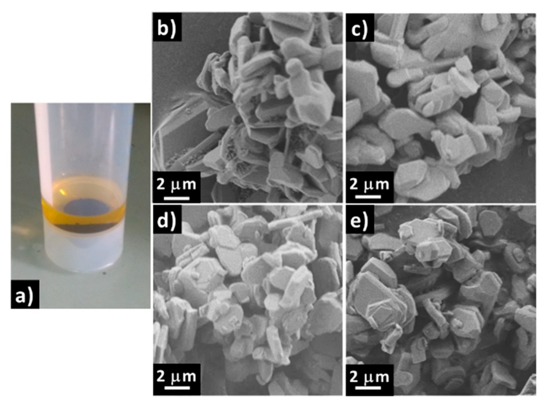
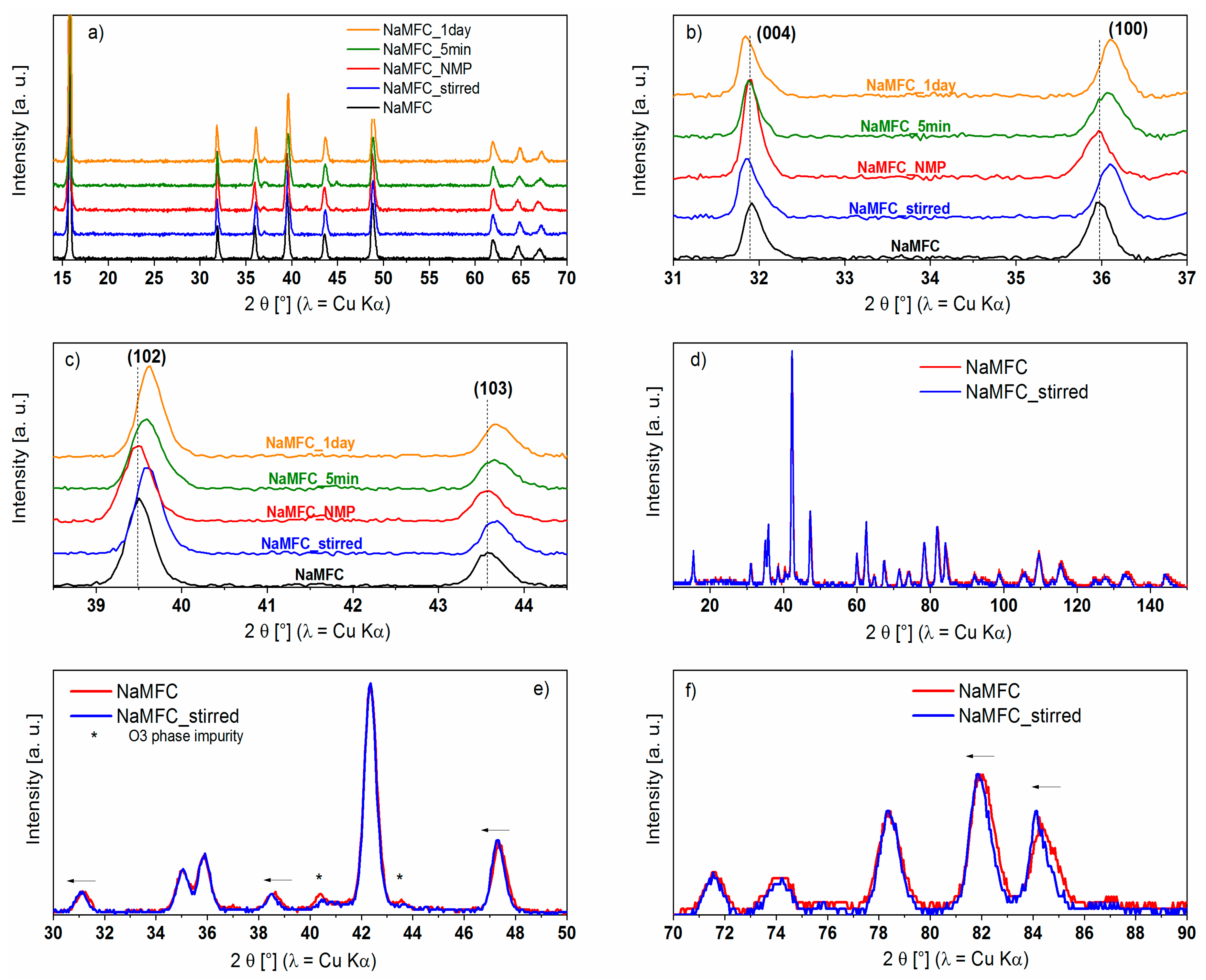
2.1. Influence of Water on NaMFC Powder

The influence of water on NaMFC material was first investigated as can be seen in Figure 1a. After immersion into water, the color turned yellowish quasi-instantly confirming the moisture sensitive character of the layered oxide material. The solution turned alkaline (pH = 10), as reported on Na 0.44 MnO 2 , either due to a partial desodiation of NaMFC and/or to the dissolution of Na 2 CO 3 , surface impurity present at the surface of all layered oxide materials [14]. Once the pH was neutralized, (by adding a droplet of 2 M H2SO4) the coloration disappeared. This could be explained by the formation of Mn(II) [16] or iron-containing [17] complexes coming from the partial hydrolysis of NaMFC and/or dissolution of impurities such as the analogous O3 phase previously identified [15]. The SEM picture of the pristine NaMFC powder (Figure 1b) is compared with that of the sample immersed in water for 5 min (Figure 1c), for one day (Figure 1e) and the one mixed in water (Figure 1d). Both samples present platelet shape particles of 1–3 μm long and ca. 300 nm thick, which is in agreement with the description in the literature for this type of material [15]. Despite the coloration of the solution (see Figure 1a), neither an effect on the morphology of the particles nor at the surface of the particles can be detected. Nevertheless, smaller round shape particles of ca. 100 nm, assigned to an impurity in the pristine sample, are hardly distinguishable for the samples in contact with water. This might be the sign of the dissolution of Na 2 CO 3 particles [9,14,18].
An elemental analysis by means of energy-dispersive X-ray spectroscopy (EDX) was additionally performed on the pristine NaMFC powder and on the one mixed in water (NaMFC_stirred). The results expressed as the ratio of metals over Co content (e.g., Na/Co, Mn/Co, etc.) are summarized in Table 1. The Na/Co ratio initially at 4.9 drops down to 3.5 supporting the loss in Na of the powder once stirred into water. Assuming that desodiation could occur through proton exchange [17], titration experiments were conducted on different aqueous solutions to follow the pH variation with increasing exposure of NaMFC to water. The pH variation could account for desodiation of NaMFC between 11% and 15% of its initial sodium content (Table 2); results were confirmed by an ICP (inductively coupled plasma-optical emission spectrometry) analysis where a difference in the Na content of 13.8% was found between NaMFC and NaMFC_stirred. Interestingly, the Mn/Co and Fe/Co ratio slightly increases and decreases respectively, revealing that a minor Fe and Co dissolution from the NaMFC material cannot be also excluded.
The XRD patterns presented in Figure 2a display Bragg peaks which can be indexed to a phase close to P2- Na 0.67 ( Mn 0.5 Fe 0.25 Co 0.25 ) O 2 reported by Liu et al [6]. No additional peaks can be seen in the samples in contact with water, meaning that no hydrated phases were detected and that the water does not decompose or alter the structure of the P2 phase [8,13,19]. In the present system, electrodes were dried under dynamic vacuum at 80 °C overnight and it was probably sufficient to remove the H2O molecules absorbed in the layered oxide material. Several insets on the reflections at 31.9°, 36.0°, 39.5°, and 43.6° are shown in Figure 2b,c. For those Bragg peaks, a shift is noticed in the XRD patterns of the samples in contact with water whereas the reference sample in contact with NMP solvent (NaMFC_NMP) does not shift. Interestingly, the (100) reflection, centered at 36.0°, shifts to higher angle (36.1°) for NaMFC_stirred and NaMFC_1 day whereas the sample immersed in water for only 5 min (NaMFC_5 min) has a smaller shift of +0.07°, indicating a correlation between the time in contact with the water (or the mixing condition) and the peak shift. This is further confirmed by the shift of +0.1° of the (102) reflection at 39.5° for NaMFC_stirred and NaMFC_1 day whereas only +0.08° is detected for NaMFC_5 min. In the literature, De Boisse et al. [20] suggested by operando XRD that the desodiation of the P2-Na0.67Mn0.5Fe0.5O2 results in a positive shift of the (h00) reflections whereas a negative shift is found for the (00l) reflections, similar to the present NaMFC/water system. Indeed, the earlier desodiation of such a phase is characterized by (i) the reduction of the Transition Metal–Transition Metal (TM–TM) distance leading to a smaller lattice parameter (described below) symbolized by the positive shift of the (10l) peaks, and (ii) the small elongation of the interlayer distance represented by the negative shift of the (00l) peaks.
High-resolution neutron diffraction data collected on the pristine NaMFC and NaMFC_stirred confirm the trend observed in the XRD analysis (Figure 2d–f). Both materials present similar cell parameters (Table 3, obtained from Lebail refinement of the neutron diffraction data) indicating that the crystallographic structure is stable in contact with water and that only a minor desodiation occurs. Additionally, the O3-NaMFC phase attributed to an impurity can be clearly identified with two distinct peaks at 40.5° and 43.6° (Figure 2e) in the pristine material. After mixing with water, the reflections belonging to this O3 phase strongly decrease revealing a minor decomposition/dissolution of the impurity. This is in agreement with the literature since it is well known that O3 phases are more sensitive to water than P2 materials [9,11,13]. This degradation could also be responsible for the coloration of the solution noticed when NaMFC is immersed in water.
To sum up, the NaMFC materials in contact with water have a similar P2-crystallographic structure to the reference sample with a smaller Na content (loss estimated at ca. 15% of the initial Na content). This loss could be compensated by proton exchange in the structure as suggested by Dall’Asta et al. [14]. In the rest of the work, the influence of this minor modification on the electrochemical performance is studied.

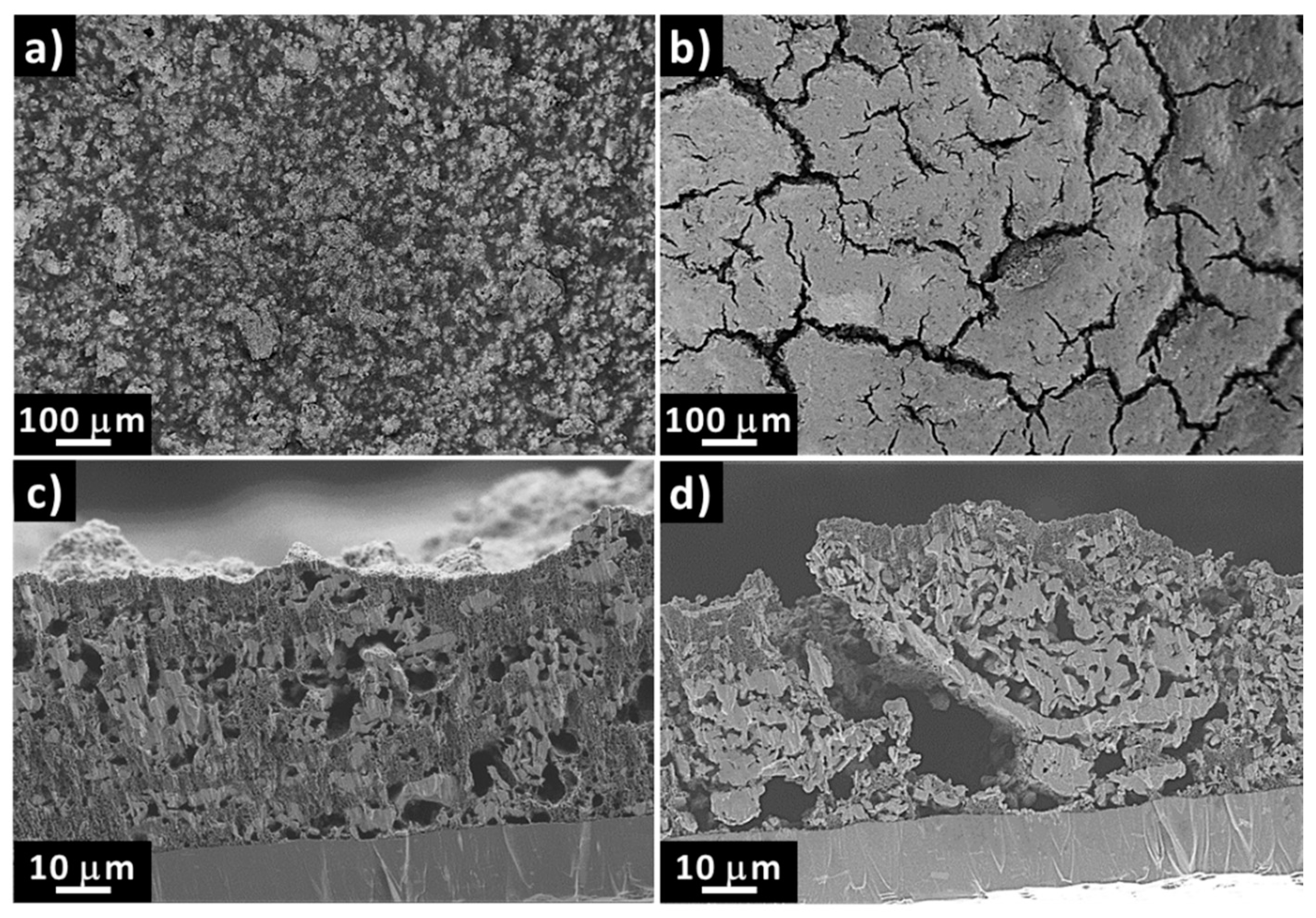
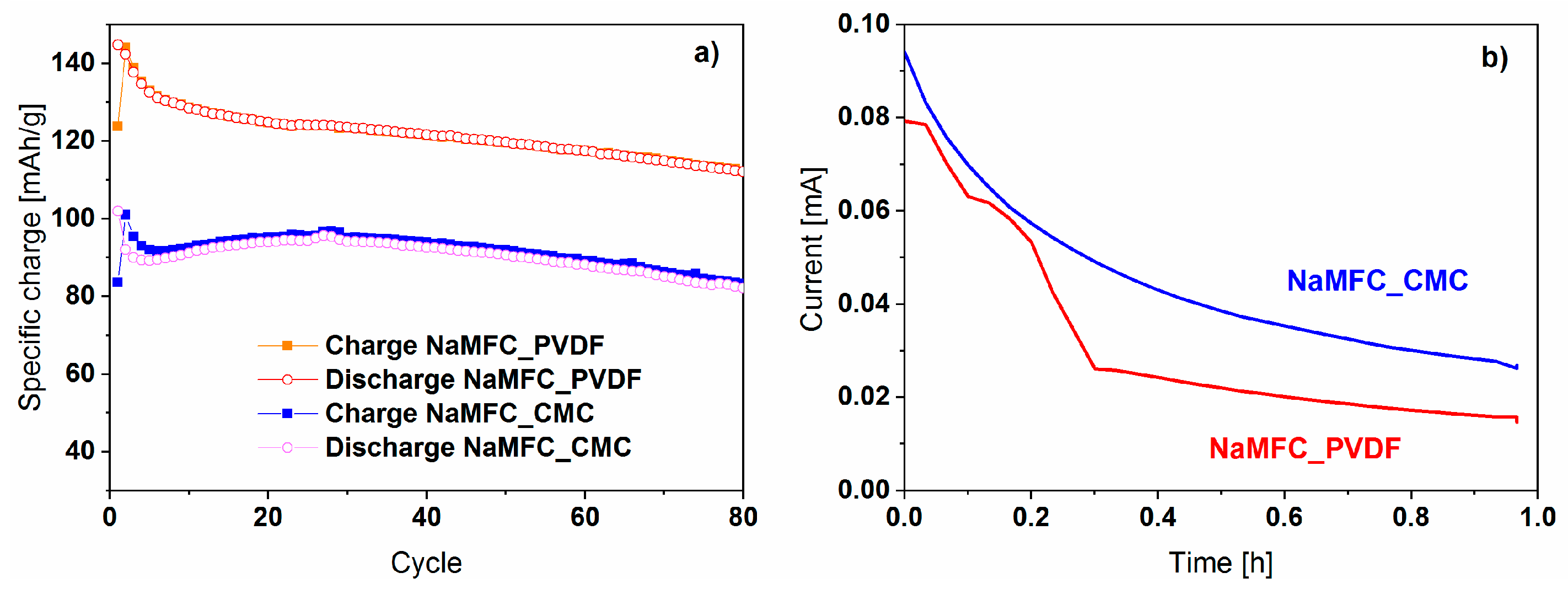
2.2. Effects of the Aqueous Slurry Preparation on the Electrochemical Performance

The surface morphology and the cross section of the electrodes prepared in water and in NMP solvents were characterized by SEM (Figure 3). A homogeneous distribution of the carbon additive (darker) and the active material particles (brighter) is observed on the surface of the NaMFC_PVDF electrode (Figure 3a). However, in the case of the NaMFC_CMC electrode, the surface morphology is different and seems to be only composed of carbon (Figure 3b) indicating that the active material is not properly embedded in the CMC binder/conductive carbon matrix. The NaMFC particles were only detected inside the numerous cracks observed at the surface of the electrode, which are commonly reported for water-based electrodes and are mainly caused by the preferred absorption of the CMC on the electrode components compared to the current collector [1,2,3]. The cross section pictures confirm the observation made on the surface of the electrodes. In fact, NaMFC_PVDF shows a good dispersion of the active material/carbon matrix through the electrode thickness (Figure 3c), whereas the carbon particles are mainly located at the surface of NaMFC_CMC (Figure 3d). Such an inhomogeneous dispersion of the active material/carbon/binder could result in worse electrochemical performance, especially at high current rates due to the lower electronic conduction of the NaMFC particles clusters in the NaMFC_CMC electrode.
The electrochemical performances of the NaMFC_PVDF and NaMFC_CMC cycled at low rate (C/10 in CCCV [Constant Current Constant Voltage] protocol) are presented in Figure 4a. During the first desodiation, the NaMFC_PVDF electrode exhibits a specific charge of 124 mAh·g−1 whereas it reaches only 83 mAh·g−1 for the NaMFC_CMC electrode. This difference is in accordance with the literature on air-exposed P2- Na 0.67 Mn 0.5 Fe 0.5 O 2 where 70% of the specific charge of the air-protected P2- Na 0.67 Mn 0.5 Fe 0.5 O 2 was obtained [9]. Considering the hypothesis of a ca. 15% desodiation of the pristine material, a specific charge of 108 mAh·g−1 should be expected, revealing that a partial desodiation is not a unique factor for the degradation of the material. Interestingly, the evolution of the current response during the potentiostatic step is close for both electrodes (Figure 4b) despite the potential low conductivity of the CMC-based electrode detected in the SEM pictures (Figure 3). Therefore, the difference in the specific charge between the two types of electrode cannot be only explained by a difference in conductivity. During the first sodiation, the difference in specific charge between the NaMFC_PVDF material (143 mAh·g−1) and the NaMFC_CMC material (102 mAh·g−1) is not reduced despite the presence of a Na reservoir coming from the Na counter electrode. Indeed, it would have been expected that the desodiated material intercalates more Na than the pristine material, as for the P2-phases, at the end of discharge, the Na content exceeds 0.8 ions per formula unit [20]. Therefore, the immersion into water not only lowers the Na content, it also prevents the insertion of additional sodium ions into the structure. After 80 cycles, NaMFC_PVDF and NaMFC_CMC deliver 112 mAh·g−1 and 88 mAh·g−1 respectively and higher coulombic efficiency (ratio discharge over charge) can be obtained for NaMFC_PVDF, which could be due to the better stability and homogeneity of the PVDF-based electrode according to the SEM observations.
The galvanostatic curves of the NaMFC_CMC and NaMFC_PVDF materials cycled in half cells are compared in Figure 5. The first charge of NaMFC_PVDF is mainly characterized by a sloping region until 4.1 V vs. Na+/Na (region I) and by a potential plateau at 4.2 V vs. Na+/Na (region II). Interestingly, no potential plateau is detected in the NaMFC_CMC material, which is further confirmed by the absence of a pronounced peak at 4.2 V vs. Na+/Na in the derivative curve (Figure 5b). The absence of this potential plateau is most probably attributed to the low specific charge obtained for the CMC-based electrode. According to Yabuuchi et al. [21], this potential plateau is due to the redox activity of the Fe3+/Fe4+ couple in the material P2- Na 0.67 Mn 0.5 Fe 0.5 O 2 . In the EDX experiment, we found a decrease of the Fe content in NaMFC_stirred, which could indicate that the high-potential plateau attributed to Fe3+/Fe4+ is not anymore electrochemically active. However, this decrease is too small to explain the absence of the entire potential plateau. During the first sodiation, the same observation can be made, with a potential plateau at an average potential of 3.8 V vs. Na+/Na (region I’) for the NaMFC_PVDF material which is not visible for the NaMFC_CMC material. However, after 50 cycles, the reaction pathway evolves since similar electrochemical curves for the charge and the discharge are displayed for both electrode materials, as the potential plateau characteristic of the Fe3+/Fe4+ redox couple disappeared from the NaMFC_PVDF curve. This behavior was already reported in a previous study [15] and it originates from the Jahn–Teller effect exhibited by the Fe(IV) atoms, which hinders the Fe3+/Fe4+ activity. Moreover, we noticed a higher polarization of 200 mV for the NaMFC_CMC (50th discharge curve) which could be attributed to a passivation layer hindering the Na pathway and/or to a “local” higher current density caused by the bad dispersion of the carbon inside the electrode. It is also interesting to note that the sodiation curve of NaMFC_PVDF electrode (after the 50th cycle) is very close to the one of NaMFC_CMC at the 1st cycle, leading us to conclude that the reaction pathway evolves during cycling for the PVDF based electrode to reach the mechanisms of CMC electrodes. The immersion in water seems to prevent and/or modify the electrochemical activity of Fe directly on the pristine, whereas in the case of PVDF-based electrodes it appears after long-term cycling. Duffort et al. [9] suggested that a reaction involving carbonate hinders the activities of the transition metal. Indeed, by reaction with CO2, carbonate CO 3 2 ion could insert in the structure of a material being exposed to air for one month. The carbonate insertion has to be compensated for by the oxidation of the transition metal together with the sodium, leading to the partial desodiation of the material. Upon cycling, it was speculated that carbonate would be oxidized and replaced by O2− anions. In our case, a possible insertion of carbonate could result in the partial or total oxidation of iron in Fe(IV), preventing the Fe to contribute to the electrochemical activity. However, the insertion of the carbonate ion into the P2 phase would result in cell parameters modification which is not in accordance with our previous observation. Therefore, only the hypothesis of a proton exchange (already mentioned) suggested in several works can be taken into account. The substitution of the Na ion by the smaller proton could fit with the described evolution of the XRD pattern [8,12,14,17].
The operando XRD experiments of the pristine NaMFC and NaMFC_stirred powders are presented in Figure 6. According to the literature, [6,20,22] the desodiation of a P2 material proceeds through a two steps phase reaction with the evolution of the P2 structure to the P2+”Z” or OP4 phase [21] and then to the final so-called “Z” or O2 structure. In P2- Na 0.67 Mn 0.5 Fe 0.25 O 2 , [23] the desodiation starts by the uniform removal of the Na from the layers but, from 3.8 V, a selective extraction from one out of two layers occurs. After that the desodiation pursues with the gliding of the layers leading to an octahedral environment for Na ions [20] and to the “Z” or O2 phase. The latter corresponds to the high voltage potential plateau observed in the galvanostatic curve. During the charge, the evolution of the XRD patterns for the pristine NaMFC follows the one of the P2- Na 0.67 Mn 0.5 Fe 0.25 O 2 : a shift of the 15.5° reflection to lower angles and then the progressive formation of the “Z” phase during the high voltage potential plateau with the appearance of a new reflection at 17.4° [21]. Despite a similar evolution of the XRD patterns at the beginning of the desodiation, the pattern at the end of the charge for the NaMFC_stirred powder reveals the absence of the “Z” phase peak but a broad reflection at 17.1° due to the P2+”Z” phase formation is observed. Indeed, as expected from the electrochemical curves, the absence of the high voltage potential plateau results in the absence of the “Z” phase for the powder immersed in water. Therefore it confirms the difficulty of the material to further oxidize and going to the “Z” phase, preventing the Na ions being in octahedral sites.

3. Discussion

In the pristine NaMFC structure, the Na atoms occupy two different crystallographic sites: Na(a) (in 2b sites) directly above the transition metal cations in the c direction (accounting for 0.42 Na) and Na(b) (in 2d sites) between the two oxygens (accounting for 0.24 Na) [23,24]. The protons exchanged in Na(b), which could not be further extracted in subsequent desodiations, could explain the 30% difference in specific charge observed between NaMFC and NaMFC_stirred. However, since the Na(b) site is the most energetically favorable site, this mechanism cannot be considered as such. On similar P2-phase, Sharma et al. [24] found that the beginning of the Na extraction is characterized by a decrease in the overall Na content due to the partial emptying of the Na(a) sites. In the meantime, a minor increase in the Na content of the Na(b) site was noticed and was interpreted as a reorganization of the Na in the material. In the present case, we could assume that part of the Na ions from the Na(a) sites is exchanged with protons. Then, two hypotheses can be formulated:
Once the charge starts, protons can travel to the more energetic Na(b) sites and could not be extracted later. However, this hypothesis suggests that only 15% of the specific charge would be lost assuming 0.1 Na lost according to the titration experiment, which is not in agreement with our observation.
Protons could not travel to the Na(b) sites because of the structural distortions created by their smaller size in comparison to Na ions. Since the 2b sites (Na(a)) are aligned with the metals along the c axis, the smaller proton would release the stress in the structure caused by Jahn–Teller distortion of the Mn(III) atoms, causing local deformations in the metal layers. Those deformations are not easily removed on further charge because it would mean the structure would have to reduce back the Jahn–Teller distortion. Therefore, in addition to the impossibility of part of the Na ions in the Na(b) to be reorganized and later play a role in the electrochemistry, the protons in the Na(a) sites might stay in the structure upon cycling to explain the jump in specific charge of 30%.
Shkrob et al. [12] suggested for water exposed Ni-rich lithiated layered oxide that the cation exchange might occur mainly on the surface of the particles rather than in the bulk. Therefore, formation of a core-shell structured particle with the proton-containing part on the shell which prevents further sodiation/desodiation of the bulk part cannot be excluded.

4. Materials and Methods

4.1. Synthesis of P2-NaMFC

In a typical NaMFC synthesis [15], acetate precursors of sodium, manganese, and cobalt were mixed with iron acetylacetonate in water-ethanol (66/33 in vol%) in stoichiometric proportion. After drying and grinding, the obtained powder was heated at 400 °C for 3 h followed by an annealing treatment at 900 °C for 12 h in a muffle oven under air. To insure a good homogeneity, an additional manual grinding of the powder in a mortar was made between the two thermal procedures. As shown in our previous work, the NaMFC powder contains 5%–10% of the O3-analogous phase.

4.2. Electrode Preparation

Aqueous-based slurries were prepared by mixing 80 wt% NaMFC, 10 wt% conductive additive (SuperC65, Imerys Graphite & Carbon, Bironico, Switzerland) and 10 wt% carboxymethylcellulose sodium salt (CMC; Alfa Aesar – Thermo Fisher GmbH, Karlsruhe, Germany) with a stand disperser device (Polytron PT2500E, Kinematica AG, Luzern, Switzerland) run at 25,000 rpm for 5 min in deionized water. In order to neutralize the alkaline conditions arising from the immersion of NaMFC in water, a solution of 1 M HCl was added. The obtained ink was cast onto an aluminum foil (used as a current collector), dried under air at room temperature and calendared to obtain a dry film thickness of ca. 45 μm. Electrodes (diameter: 13 mm) with an active material loading of around 5 mg·cm−2 were punched and dried under dynamic vacuum at 80 °C for 12 h. For comparison, PVDF-based electrodes were prepared under similar conditions by using N-methyl pyrrolidone (NMP) as solvent instead of water and without addition of the acidic solution. The samples are called hereafter NaMFC_PVDF and NaMFC_CMC for the organic solvent preparation and the aqueous one respectively.

4.3. Sample Preparation for Investigating the Effect of Water on NaMFC Powder

To investigate the impact of water during the slurry preparation, NaMFC was dispersed and stirred in water alone (NaMFC_stirred). As reference samples, the material was also immersed into deionized water for 5 min (NaMFC_5 min) and for one day (NaMFC_1 day) without stirring and into NMP with stirring (NaMFC_NMP). All mixtures were centrifuged and the obtained powders were dried at 80 °C for 12 h.

4.4. Titration

Prior to centrifugation (see part 4.3), all the aqueous solutions were diluted five times with deionized water. The titration was performed by using a 0.02 M HCl solution as titrant solution and the evolution of pH was followed with a pH electrode (Metler Toledo InLab 413, Colombus, USA). Each titration was reproduced 4 times to insure a proper statistic on the estimation of the desodiation level.

4.5. X-ray Diffraction (XRD)

XRD measurements were performed in reflection mode at 25 °C with a PANalytical Empyrean diffractometer using Cu Kα-radiation. The patterns were collected for 1 h from 12° to 70° with a step size of 0.0334°. The operando measurements were performed using a homemade in situ cell [25] with a powder electrode made by mixing 70 wt% of active material with 30 wt% carbon additive (superC65).

4.6. Scanning Electron Microscopy (SEM) Coupled with Energy-Dispersive X-ray Spectroscopy (EDX)

SEM measurements were performed using a Carl Zeiss Ultra55 scanning electron microscope in both the secondary electron and the InLens modes at 3 kV. For the cross section, the electrodes were cut using an ion-milling machine (IM4000Plus, Hitachi, Tokyo, Japan) at 4 kV for 5 h. The EDX analysis was performed on similar samples at 15 kV with an EDAX APOLLO XV Silicon Drift Detector and using the TEAM 4.51 software for the data processing.

4.7. Neutron Diffraction

Neutron diffraction experiments were carried out on the HRPT (High-Resolution Powder diffractometer for Thermal Neutrons) beamline at SINQ (PSI, Villigen, Switzerland). Deuterated water was used to prepare the sample NaMFC_stirred. The samples were loaded in 6 mm vanadium cans and sealed with an indium wire in an Ar-filled glovebox. Neutron scattering data were collected at 300 K using a λ = 1.494 Å wavelength in the 5–165° 2 θ range. LeBail refinement was carried out using the FullProf Rietveld package [26].

4.8. Electrochemistry

Electrochemical cells were assembled in an Ar-filled glove box using a glass fiber separator and metallic sodium as counter electrode. An amount of 1 M NaClO4 dissolved in polypropylene carbonate (PC) was used as electrolyte. The cells were cycled using an Astrol cycling device in galvanostatic mode between 2.1 V and 4.5 V (versus Na+/Na) at a C/10 rate at 25 °C. To avoid strong kinetic effects, potentiostatic steps at 4.5 V and 2.1 V of 1 h and 30 min were respectively applied.

4.9. Inductively Coupled Plasma–Optical Emission Spectrometry (ICP–OES)

Powder samples were digested in aqua regia and diluted with Milli-Q water. The measurements were performed with a VISTA AX apparatus (Varian, Australia; Agilent Technologies, Santa Clara, USA) and with an error estimated at 0.2%.

5. Conclusions

The effect of electrode formulation and especially the impact of water-based slurry for the layered oxide material NaMFC were investigated. Despite a stable overall crystallographic structure, a shift of some reflections in the XRD pattern revealed that a partial desodiation of the material occurred during electrode fabrication. The electrochemical performance of the CMC-based electrode resulted in lower specific charge compared to the standard PVDF-based electrode in half-cell systems. The analysis of the galvanostatic curves combined with operando XRD patterns enabled the suggestion that protons could have been inserted in the structure modifying the electrochemical pathway for the Na ions.

Author Contributions

experimentation, C.M. and S.P.; data curation, C.M. and E.M.; writing C.M. and C.V.; supervision, C.M. and C.V.

Funding

This research received no external funding.

Acknowledgments

This work was performed within the SCCER Heat and Storage Network (Swiss Competence Center for Heat and Electricity Storage). The authors thank D. Sheptyakov (HRPT, SINQ, PSI, proposal number 20160962) for the help with the data acquisition and Silvia Köchli for the ICP–OES analysis.

Conflicts of Interest

The authors declare no conflict of interest.

References

  1. Chong, J.; Xun, S.; Zheng, H.; Song, X.; Liu, G.; Ridgway, P.; Wang, J.Q.; Battaglia, V.S. A comparative study of polyacrylic acid and poly(vinylidene difluoride) binders for spherical natural graphite/LiFePO4 electrodes and cells. J. Power Sources 2011, 196, 7707–7714. [Google Scholar] [CrossRef]
  2. Jeschull, F.; Brandell, D.; Wohlfahrt-Mehrens, M.; Memm, M. Water-Soluble Binders for Lithium-Ion Battery Graphite Electrodes: Slurry Rheology, Coating Adhesion, and Electrochemical Performance. Energy Technol. 2017, 5, 2108–2118. [Google Scholar] [CrossRef]
  3. Lestriez, B. Functions of polymers in composite electrodes of lithium ion batteries. C. R. Chim. 2010, 13, 1341–1350. [Google Scholar] [CrossRef]
  4. Yabuuchi, N.; Kubota, K.; Dahbi, M.; Komaba, S. Research development on sodium-ion batteries. Chem. Rev. 2014, 114, 11636–11682. [Google Scholar] [CrossRef] [PubMed]
  5. Delmas, C.; Braconnier, J.-J.; Hagenmuller, P.-A. A new variety of LiCoO2 with an unusual oxygen packing obtained by exchange reaction. Mater. Res. Bull. 1982, 17, 117–123. [Google Scholar] [CrossRef]
  6. Liu, L.; Li, X.; Bo, S.-H.; Wang, Y.; Chen, H.; Twu, N.; Wu, D.; Ceder, G. High-Performance P2-Type Na2/3(Mn1/2Fe1/4)O2 Cathode Material with Superior Rate Capability for Na-Ion Batteries. Adv. Energy Mater. 2015, 5, 1500944. [Google Scholar] [CrossRef]
  7. Li, X.; Wu, D.; Zhou, Y.-N.; Liu, L.; Yang, X.-Q.; Ceder, G. O3-type Na(Mn0.25Fe0.25Co0.25Ni0.25)O2: A quaternary layered cathode compound for rechargeable Na ion batteries. Electrochem. Commun. 2014, 49, 51–54. [Google Scholar] [CrossRef]
  8. Buchholz, D.; Chagas, L.G.; Vaalma, C.; Wu, L.; Passerini, S. Water sensitivity of layered P2/P3-NaxNi0.22Co0.11Mn0.66O2 cathode material. J. Mater. Chem. A 2014, 2, 13415–13421. [Google Scholar] [CrossRef]
  9. Duffort, V.; Talaie, E.; Black, R.; Nazar, L.F. Uptake of CO2 in Layered P2-Na0.67Mn0.5Fe0.5O2: Insertion of Carbonate Anions. Chem. Mater. 2015, 27, 2515–2524. [Google Scholar] [CrossRef]
  10. Paulsen, J.M.; Dahn, J.R. Study of the layered manganese bronzes. Solid State Ion. 1999, 126, 3–24. [Google Scholar] [CrossRef]
  11. Sathiya, M.; Hemalatha, K.; Ramesha, K.; Tarascon, J.M.; Prakash, A.S. Synthesis, Structure, and Electrochemical Properties of the Layered Sodium Insertion Cathode Material: NaNi1/3Mn1/3Co1/3O2. Chem. Mater. 2012, 24, 1846–1853. [Google Scholar] [CrossRef]
  12. Shkrob, I.A.; Gilbert, J.A.; Phillips, P.J.; Klie, R.; Haasch, R.T.; Bareno, J.; Abraham, D.P. Chemical Weathering of Layered Ni-Rich Oxide Electrode Materials: Evidence for Cation Exchange. J. Electrochem. Soc. 2017, 164, A1489–A1498. [Google Scholar] [CrossRef] [Green Version]
  13. Lu, Z.; Dahn, J.R. Intercalation of Water in P2, T2 and O2 Structure Az[CoxNi1/3−xMn2/3]O2. Chem. Mater. 2001, 13, 1252–1257. [Google Scholar] [CrossRef]
  14. Dall’Asta, V.; Buchholz, D.; Chagas, L.G.; Dou, X.; Ferrara, C.; Quartarone, E.; Tealdi, C.; Passerini, S. Aqueous Processing of Na0.44MnO2 Cathode Material for the Development of Greener Na-Ion Batteries. ACS Appl. Mater. Interfaces 2017, 9, 34891–34899. [Google Scholar] [CrossRef] [PubMed]
  15. Marino, C.; Marelli, E.; Villevieille, C. Impact of cobalt content in Na0.67MnxFeyCozO2 (x + y + z = 1), a cathode material for sodium ion batteries. RSC Adv. 2017, 7, 13851–13857. [Google Scholar] [CrossRef]
  16. Kadarmandalgi, S.G. Spot Test for Detection of Manganese. J. Chem. Educ. 1964, 41, 437–438. [Google Scholar] [CrossRef]
  17. Blesa, M.C.; Moran, E.; Menendez, N.; Tornero, J.D.; Torron, C. Hydrolysis of Sodium Orthoferrite. Mater. Res. Bull. 1993, 28, 837–847. [Google Scholar] [CrossRef]
  18. Polfus, J.M.; Yildiz, B.; Tuller, H.L.; Bredesen, R. Adsorption of CO2 and Facile Carbonate Formation on BaZrO3 Surfaces. J. Phys. Chem. C 2018, 122, 307–314. [Google Scholar] [CrossRef]
  19. Nam, K.W.; Kim, S.; Yang, E.; Jung, Y.; Levi, E.; Aurbach, D.; Choi, J.W. Critical Role of Crystal Water for a Layered Cathode Material in Sodium Ion Batteries. Chem. Mater. 2015, 27, 3721–3725. [Google Scholar] [CrossRef]
  20. Mortemard de Boisse, B.; Carlier, D.; Guignard, M.; Bourgeois, L.; Delmas, C. P2-NaxMn1/2Fe1/2O2 phase used as positive electrode in Na batteries: Structural changes induced by the electrochemical (de)intercalation process. Inorg. Chem. 2014, 53, 11197–11205. [Google Scholar] [CrossRef] [PubMed]
  21. Yabuuchi, N.; Kajiyama, M.; Iwatate, J.; Nishikawa, H.; Hitomi, S.; Okuyama, R.; Usui, R.; Yamada, Y.; Komaba, S. P2-type Nax[Mn1/2Fe1/2]O2 made from earth-abundant elements for rechargeable Na batteries. Nat. Mater. 2012, 11, 512–517. [Google Scholar] [CrossRef] [PubMed]
  22. Talaie, E.; Duffort, V.; Smith, H.L.; Fultz, B.; Nazar, L.F. Structure of the high voltage phase of layered P2-Na1/3−z[Mn1/2Fe1/2]O2 and the positive effect of Ni substitution on its stability. Energy Environ. Sci. 2015, 8, 2512–2523. [Google Scholar] [CrossRef]
  23. Kjeldgaard, S.; Birgisson, S.; Kielland, A.G.; Iversen, B.B. Operando powder X-ray diffraction study of P2-NaxNi0.3Mn0.7O2 cathode material during electrochemical cycling. J. Appl. Crystallogr. 2018, 51, 1304–1310. [Google Scholar] [CrossRef]
  24. Sharma, N.; Tapia-Ruiz, N.; Singh, G.; Armstrong, A.R.; Pramudita, J.C.; Brand, H.E.A.; Billaud, J.; Bruce, P.G.; Rojo, T. Rate Dependent Performance Related to Crystal Structure Evolution of Na0.67Mn0.8Mg0.2O2 in a Sodium-Ion Battery. Chem. Mater. 2015, 27, 6976–6986. [Google Scholar] [CrossRef]
  25. Bleith, P.; Kaiser, H.; Novák, P.; Villevieille, C. In situ X-ray diffraction characterisation of Fe0.5TiOPO4 and Cu0.5TiOPO4 as electrode material for sodium-ion batteries. Electrochim. Acta 2015, 176, 18–21. [Google Scholar] [CrossRef]
  26. Rodriguez-Carjaval, J. Recent advances in magnetic structure determination by neutron powder diffraction. Phys. B 1993, 192, 55–69. [Google Scholar] [CrossRef]
Figure 1. (a) Picture of P2- Na 0.67 Mn 0.6 Fe 0.25 Co 0.15 O 2 (NaMFC) powder immersed in water showing the yellowish coloration; SEM pictures of (b) pristine NaMFC, (c) NaMFC_5 min immersed in water, (d) NaMFC_stirred in water and (e) NaMFC_1 day immersed in water.
Batteries 04 00066 g001
Figure 2. XRD patterns of NaMFC and NaMFC_stirred for (a) a full 2 θ range, (b) between 31° and 37°, (c) between 38.5° and 44.5°; Neutron diffraction patterns of NaMFC and NaMFC_stirred for (d) a full 2 θ range, (e) between 30° and 50°, (f) between 70° and 90°.
Batteries 04 00066 g002
Figure 3. SEM pictures of the (a) surface of NaMFC_PVDF, (b) surface of NaMFC_CMC, (c) cross-section NaMFC_PVDF and (d) cross-section NaMFC_CMC. PVDF = polyvinylidene fluoride. CMC = carboxymethylcellulose.
Batteries 04 00066 g003
Figure 4. (a) Electrochemical performance of NaMFC electrodes obtained at C/10 using CCCV (Constant Current Constant Voltage) protocol; (b) Evolution of the current during the potentiostatic step at 4.5 V vs. Na+/Na at the end of the 1st charge.
Batteries 04 00066 g004
Figure 5. (a) Galvanostatic curves of NaMFC electrodes cycled at C/10 at the 1st cycle; (b) Derivative curve dQ/dV of the galvanostatic curve of NaMFC electrodes cycled at C/10 at the 1st cycle where the absence of the intense peak at 4.2 V vs. Na+/Na for the NaMFC_CMC electrode during the charge is obvious; (c) Galvanostatic curves of NaMFC electrodes at the 50th cycle when the cells are cycled at C/10 rate.
Batteries 04 00066 g005
Figure 6. Contour plot representation of an Operando XRD experiment of (a) the pristine NaMFC and (b) the NaMFC_stirred materials cycled vs. Na at a rate of C/10 and their corresponding galvanostatic curves.
Batteries 04 00066 g006
Table 1. EDX results for P2-Na0.67Mn0.6Fe0.25Co0.15O2 (NaMFC) pristine powder and NaMFC_stirred sample.
SampleNa/CoMn/CoFe/Co
NaMFC4.94.52.4
NaMFC_stirred3.54.82.2
Table 2. Estimation by titration of the desodiation level from the pristine NaMFC (Na content at 0.67) with a precision of ±1%.
SampleNaMFC_5 minNaMFC_1 DayNaMFC_Stirred
Desodiation level [%]111614
Na content in NaMFC0.59630.56280.5762
Table 3. Cell parameters of the P2 phase (P63/mmc) NaMFC and NaMFC_stirred refined following the Lebail method using the neutron diffraction data.
Samplea (Å)c (Å)V (Å3)
NaMFC2.88200 (6)11.2095 (5)80.631 (4)
NaMFC_stirred2.88155 (6)11.2309 (4)80.760 (4)

