A Bilevel Equalizer to Boost the Capacity of Second Life Li Ion Batteries

1
Engineering Technology Department, University of Toledo, 2801 W. Bancroft, Toledo, OH 43606, USA
2
Electrical Engineering and Computer Science Department, University of Toledo, 2801 W. Bancroft, Toledo, OH 43606, USA
*
Author to whom correspondence should be addressed.
Batteries 2019, 5(3), 55; https://doi.org/10.3390/batteries5030055
Submission received: 18 April 2019
/
Revised: 29 June 2019
/
Accepted: 8 July 2019
/
Published: 1 August 2019
Abstract
:There is a strong interest in second life applications for the growing number of used electric vehicle (EV) batteries, but capacity variations amongst these used cells present a problem. Even when these cells are matched for capacity, some imbalance is bound to remain, and a few lower capacity cells are also likely to develop after the pack begins its second life. Conventional cell voltage equalizers (EQU) do not address this problem, and they only provide a battery discharge capacity that is exactly equal to that of the weakest cell in the pack. This can easily result in a capacity loss of perhaps 20% to 25%, or more. This indicates the need for a new class of EQUs that can provide a discharge capacity that is close to the average of the cells, instead of the weakest cell. It is proposed to call these “capacity EQUs”, and the properties they must have are described. One such EQU is the bilevel equalizer (BEQ), described previously. This present paper provides an enhanced analysis of the BEQ and improved modelling methods. It also presents more details that are necessary to implement the microcontroller algorithm for the BEQ hardware.
1. Introduction
As the market for electric vehicles (EVs) continues to grow, so too will the number of used EV batteries, which are typically replaced when they degrade to about 80% of their original capacity. Although unsuitable for EVs, these batteries are very cost-effective for other applications, and re-use lifetimes in the range of 10 years have been estimated [1,2,3,4]. However, variations in the cell capacity will be wider than for new cells, making it necessary to match cells. Although these used cells may be initially matched, the capacity variations are still likely to reappear as the cells continue to age, and this should be considered.
All large lithium ion batteries must use an electronic equalizer (EQU) to balance the cell voltages. Due to their low cost, the vast majority of these are passive equalizers (PEQ) [5] that simply connect a resistor across each of the series connected cells until all have been drained to match the lowest cell voltage in the pack. PEQs suffer the obvious problem of heating, and they do nothing to compensate for a lower capacity cell that may appear as the battery ages. Unfortunately, this weakest cell will determine the capacity of the entire battery. The PEQ heating problem can be reduced by using active equalizers (AEQ) [6,7,8,9,10,11,12,13,14,15,16,17,18,19,20] that transfer the charge between the cells, but they are seldom used due to their higher cost. The cost also limits the size of the AEQ equalization currents, so they are not very effective in compensating for large imbalances in the cell capacity. This means the battery discharge capacity remains essentially the same as that of the weakest cell in the pack for both PEQs and low current AEQs.
When the cells are new, PEQs are perhaps adequate, and developers appear willing to accept the capacity reduction due to one or more weak cells that appear as the battery ages. However, the weak cell problem is expected to be more serious for second life applications, and it will appear much earlier. This indicates the need for a new type of EQU that mitigates the weak cell problem and that is also cost effective. One such EQU is an AEQ/PEQ hybrid called the bilevel equalizer (BEQ) [21,22,23], which is described below.
Most EQUs simply balance the cell voltages at some point in the operating cycle, typically while the battery is at rest, and no attempt is made to compensate for lower capacity cells that appear in older batteries. Since these EQUs are limited to only balancing cell voltages, it is logical to call them “voltage EQUs”. However, the weak cell problem indicates a need for a new class of EQUs that can transfer fairly large amounts of charge to or from these cells to compensate for their lower capacity, and this must be done while the battery is operating. Of course, such EQUs cannot actually equalize or even change the cell capacities, but they have a similar effect. Thus, they might be called “capacity equalizers” or “boost equalizers”. Whereas voltage EQUs only provide a battery discharge capacity equal to that of the weakest cell, capacity equalizers can provide a battery discharge capacity very close to the average capacity of the cells.
2. The Bilevel Equalizer
Since a capacity EQU must be able to transfer the charge between cells, only an AEQ or an AEQ/PEQ hybrid can qualify, and it must meet the following requirements:
- (1)
- Low to moderate cost.
- (2)
- Operate while the battery is charging and discharging.
- (3)
- Provide equalization currents of an adequate size, relative to the battery current, capacity, and degree of capacity imbalance amongst the cells.
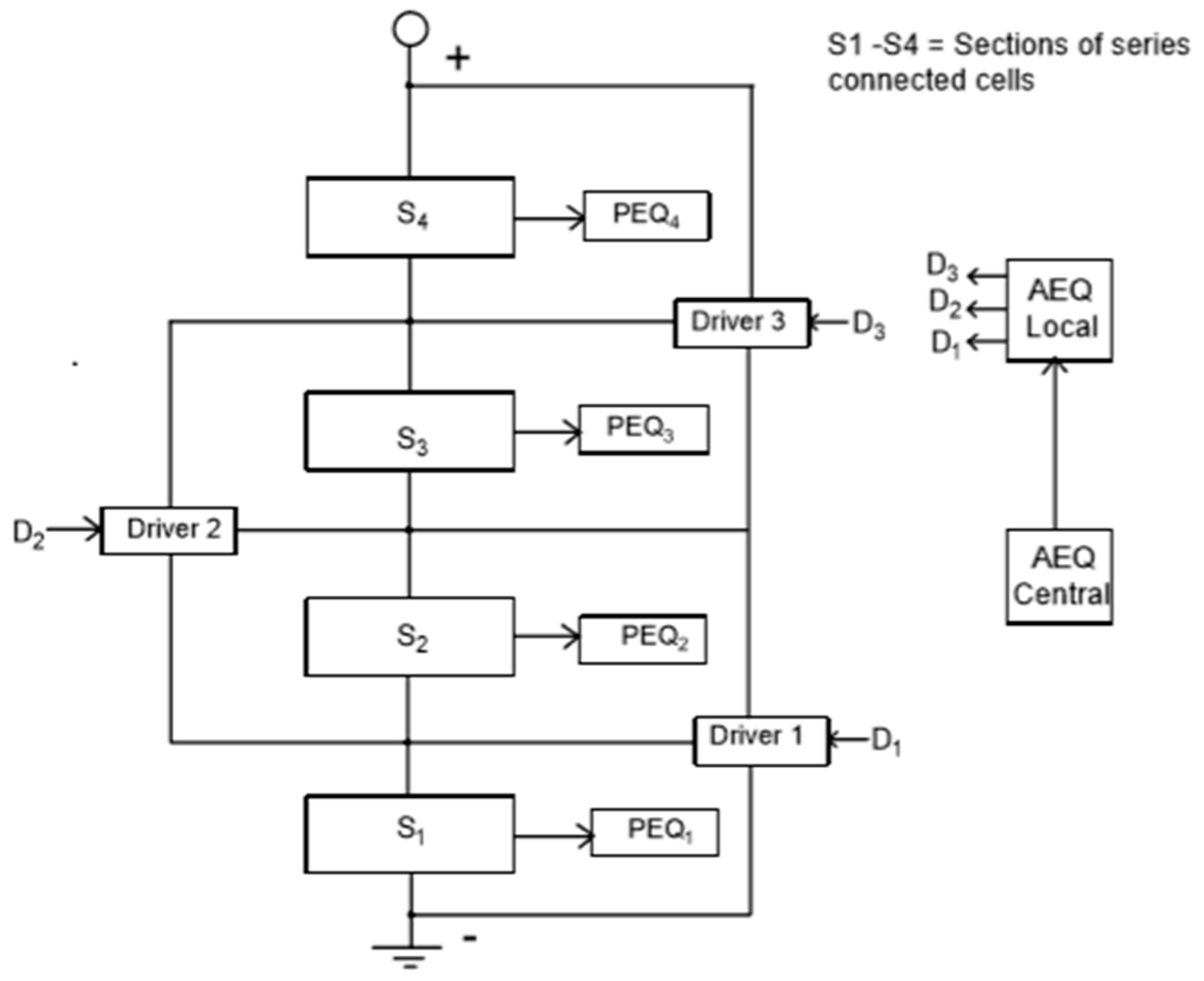
One such EQU is the BEQ, so called because it provides equalization at two voltage levels. Figure 1 shows the block diagram of a BEQ connected to a battery, where the series connected cells are divided into sections of perhaps 4 to 14 cells each. Each section has a separate PEQ to equalize its own cell voltages, and the section voltages are equalized by AEQs. Since the PEQ and AEQ are separate, a BEQ also can be implemented by adding an AEQ retro kit to an existing PEQ system. The PEQ and AEQ circuits are shown in Figure 2 and Figure 3a, respectively. Figure 3b shows the AEQ inductor current and gate drive waveforms.
The BEQ will be much lower in cost than a conventional AEQ because it has a much smaller number of AEQ drivers. For example, an inductive AEQ for a 196-cell battery would require 195 AEQ drivers (number of cells—1), but a BEQ with 14 cells/section and 14 sections would only require 13 AEQ drivers (number of sections—1). It also should be noted that inductive AEQs are lower in cost than other types of AEQs that use transformers. Each PEQ only has to equalize 14 cells instead of 196, so this implies that the PEQ currents can be reduced, since the cell voltage variations within a section are usually less than those for the entire battery. This not only reduces heating, but the cost of the resistors as well.
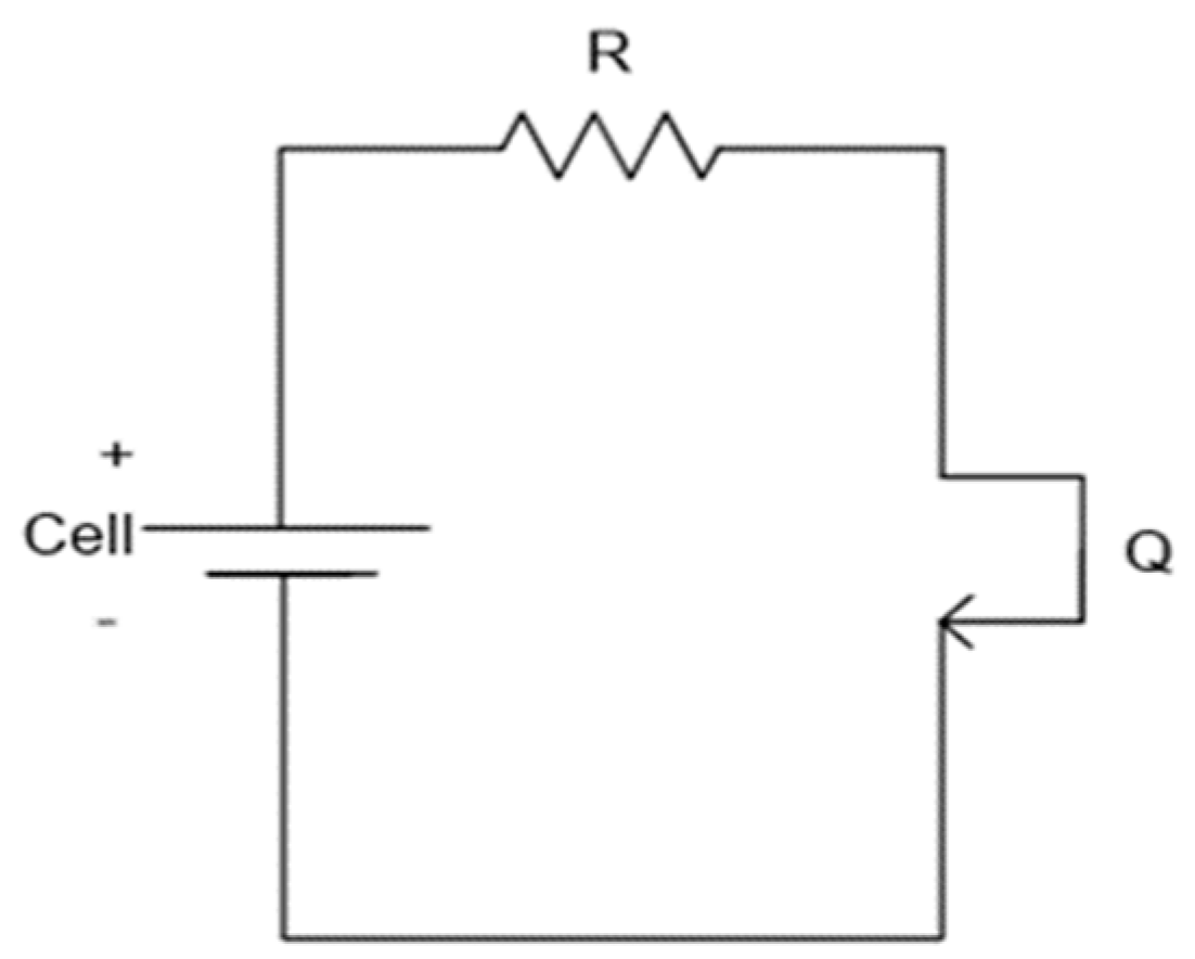
The operation of the PEQ in Figure 2 is quite obvious, i.e., each field effect transistor (FET) is turned on until its cell reaches the lowest cell voltage in the pack. The operation of the AEQ in Figure 3 is also quite simple. For example, if Q1 is switched on, IL flows from S1 until it reaches a peak at T1 where Q1 turns off and IL commutates to the body diode of Q2. The energy stored in L1 is then transferred to S2 until IL = 0 at T2. This process can be performed simultaneously for other AEQ drivers so that energy can be transferred between any two sections in the pack.
3. Analysis
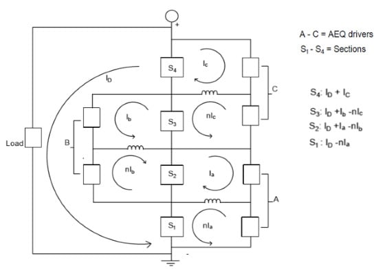
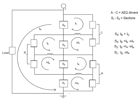
The following examples show how the required AEQ equalization currents in the BEQ can be calculated for a specific design as illustrated in Figure 4. This calculation was first introduced in [22,23], but the procedure and the results are explained here in more detail. Although the analyses in these previous references was correct, the derivation procedure for the AEQ equations needed further clarification. This analysis has been enhanced through the use of AEQ flow diagrams such as that in Figure 5 which shows how the AEQ currents flow between the battery sections and the AEQ drivers. These flow diagrams indicate the directions of the AEQ currents, but they are not exact equivalent circuits since they do not have the same topology as the actual circuit. The proper directions for the currents are usually obvious, but if the wrong direction is assigned, the calculated current will have the correct magnitude but a negative value. Although the BEQ can be operated as a voltage EQU while the battery is at rest, the intent here is to operate as a capacity EQU, so it is assumed the battery is active, and several transfers can take place simultaneously.
The Ah capacity rating of each section is defined to be the same as that of the lowest capacity cell (weakest cell) in the section. During discharge, this will be the lowest voltage cell in the section, and during charging it will be the highest voltage cell. During the discharge the AEQ, logic acts to transfer the charge from the stronger sections to the weaker ones. This increases the battery discharge capacity because it delays the time at which the weakest cell reaches its minimum voltage limit. During charging, the logic is the opposite. In this case the weakest cell in each section will have the highest voltage, and the AEQ transfers charge from the weaker sections to the stronger ones. This increases the charging capacity since it delays the time at which the weakest cell reaches its maximum voltage limit.
3.1. Example 1
This example is for a discharge cycle for a battery similar to the one in Figure 1, with 4 sections and 14 cells/section.
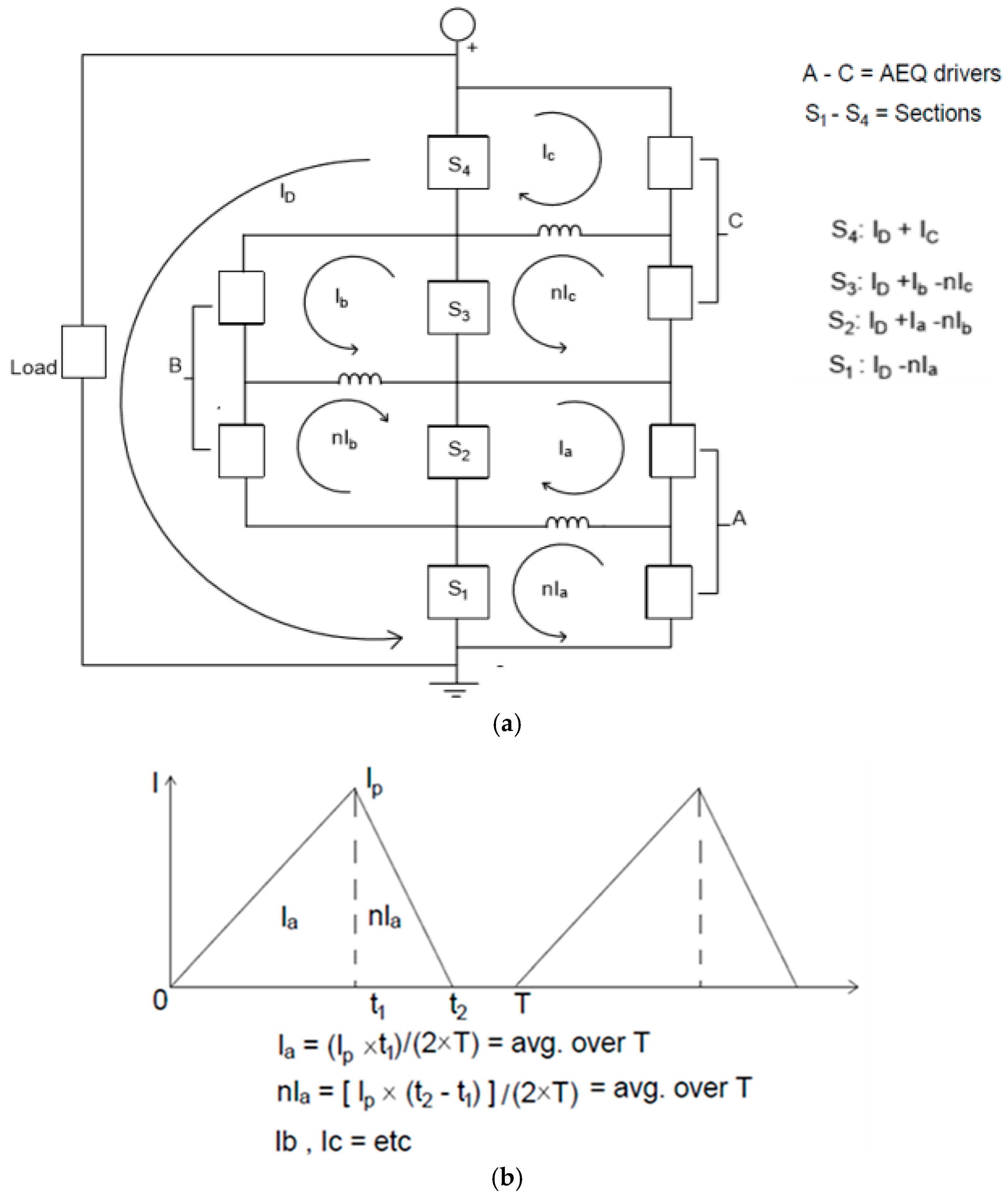
The 4 sections, S1–S4, have the following capacities: AH1 = 81 Ah (−10%) and AH2 = AH3 = AH4 = 90 Ah. A weak section at S1 or S4 is the worst case, since it can only be fed from one direction. Three AEQ drivers (A, B, and C) are required to transfer the charge from S2–S4 into S1 since it is the weakest section. The PEQs are not used during the discharge since they cannot transfer the charge to a cell.
Figure 4a shows all of the loop currents for sections S1 to S4 and AEQ drivers A to C. Since the section voltages are DC, only the DC components of the AEQ currents can transfer any average energy. Figure 4b shows how Ia and η × Ia can be calculated from the Ia waveform. Because of losses, the current exiting an AEQ driver is reduced by a factor, η, e.g., the current into A = Ia and the current out of A = η × Ia (all section voltages are approximately the same). η will be called the AEQ efficiency. The total currents through S1 to S4 are also shown in Figure 4a.
Rather than using the complete circuit in Figure 4, Figure 5 provides a simplified flow diagram showing the equalization currents between the sections and the AEQ drivers.
Assume the following specifications:
- ID = discharge current = 30 Adc
- T = discharge time
- η = AEQ efficiency = 0.9
All sections are to reach full discharge at the same time. Therefore:
(ID − η × Ia) T = AH1
(ID + Ia − η × Ib) T = AH2
(ID + Ib − η × Ic) T = AH3
(ID + Ic) T = AH4
Defining P = 1/T and AH = AH2 to AH4:
Solving Equation (5) for Ia, Ib, Ic, and P, Ia = 2.43 Adc, Ib = 1.71 Adc, Ic = 0.9 Adc, and T = 2.92 h. The capacity is 87.38 Ah, as compared to 81 Ah when only a PEQ is used, an increase of 7.9%. Note that the average capacity of the 4 sections is 87.75 Ah, so the BEQ provides a capacity very close to the average of the sections, and thus it qualifies as a capacity EQU.
As stated above, the logic selects the AEQ transfer operations based on the lowest cell voltage in each section. However, the AEQ currents and other effects produce slight variations in the cell voltages, so the AEQ currents do not actually flow continuously but switch on and off as the discharge progresses. Therefore, the peak DC current will be higher than its average over the time period T. The values calculated from Equation (5) are the average DC values, so instead of being designed to produce a max of 2.43 Adc, each AEQ unit should be designed to provide a somewhat higher max current, perhaps 3.6 Adc. This allows the AEQ unit to produce the required average value of 2.43 Adc as it switches on and off over the discharge period. This value of 3.6 Adc (12% of ID) is economical for a BEQ whose 3 AEQ drivers operate at the section level, but since there are 56 cells, it would be very expensive for a conventional AEQ operating on each cell and requiring 55 AEQ drivers.
3.2. Example 2
If the AH1 rating in Example 1 is changed to 72 Ah (−20%), the results from Equation (5) are, Ia = 5.02 Adc, Ib = 3.52 Adc, Ic = 1.85 Adc, and T = 2.826 h. The capacity is now 84.7 Ah, which is an increase of 17.7% over the 72 Ah of a PEQ. The average capacity of the sections is 85.5 Ah, which is still very close to the calculated 84.7 Ah capacity. As before, the actual AEQ maximum current ratings should be somewhat greater than 5.02 Adc, perhaps 7.5 Adc.
Although this 7.5 Adc current is 25% of ID, AEQ currents of this size are still easily achieved for this BEQ with 3 AEQ drivers, but would probably be cost prohibitive for a cell level AEQ for 56 cells.
4. Experimental Results
A BEQ lab prototype was developed and tested with a cobalt oxide Li ion battery with 24S-8Pcells, i.e., there were 24S modules, each with 8P cells. The battery pack is shown in Figure 6, and the BEQ laboratory prototype is shown in Figure 7.
- Discharge Capacity of each 8P cell module: 32 Ah (2.8 Vdc < Vcell < 4.0 Vdc)
- Discharge current: ID = 7 Adc
- Number of sections: 6
- Number of series connected modules/section: 4
The BEQ specifications:
- Number of AEQ drivers: 5
- AEQ equalization current at a section voltage of 14 Vdc (3.5 V/cell): 1.9 Adc (this is the current flowing out of a section)
- AEQ efficiency at a section voltage of 14 Vdc: 72%
- AEQ frequency: 16.13 kHz
This AEQ uses an open loop control, so at the fixed frequency of 16.13 kHz the equalization current will vary over the cell voltage range of 2.8 Vdc to 4.0 Vdc used for these tests.
4.1. Test #1
To compare the calculations with the experimental results, a test was performed with a 25% imbalance by removing 2 of the 8P cells from module #9 in section S3. Therefore, the capacity of S3 = 24 Ah, while all other sections remain at 32 Ah. Figure 8 shows the equivalent circuit during discharge for this case. From Figure 8, using the variables similar to those in Equations (1)–(5):
(ID + Ia) T = AH1
(ID − ηIa + Ib) T = AH2
(ID − ηIb − ηIc) = AH3
(ID + Ic − ηId) T = AH4
(ID + Id − ηIe) T = AH5
(ID + Ie) T = AH6
Defining P = 1/T, AH = AH1, 2, 4, 5 and 6, and U = unitary vector:
Solving Equation (12), Ia = 0.486 Adc, Ib = 0.836 Adc, Ic = 1.09 Adc, Id = 0.836, Ie = 0.486, and T = 4.27 h. The capacity is 29.92 Ah, as compared to 24 Ah when only a PEQ is used, an increase of 24.7%. Note that the average capacity of the 6 sections is 30.67 Ah, so the BEQ provides a battery capacity very close to the average of the sections. The calculated and measured results are summarized in Table 1.
A full discharge test at an average ID = 7 Adc was then performed on the battery in the lab with the BEQ turned off. This is the same as a PEQ-only system since the PEQ has no effect on the discharge capacity, which was measured at 24.2 Ah, as compared to 24 Ah used in the calculations.
The BEQ was then turned on, and the battery was given a full charge and then discharged at an average ID = 7 Adc. The measured discharge capacity was 28.68 Ah, an increase of 18.6% above the PEQ test and 96% of the calculated value. The calculations indicate that an average AEQ current of 1.09 Adc is needed, so the actual maximum DC value of 1.9 Adc appears to be adequate to produce a 1.09 Adc average over the cycle (recall that the AEQ currents modulate on and off during the discharge). The results are summarized in Table 1.
4.2. Test #2
Now, consider a more extreme case, with a 50% reduction in S3, i.e., AH3 = 16 Ah.
Solving Equation (12), Ia = 1.079 Adc, Ib = 1.89 Adc, Ic = 2.42 Adc, Id = 1.86 Adc, Ie = 1.08 Adc, and T = 3.9 h, and the capacity is 27.29 Ah. This indicates that the maximum AEQ current of 1.9 Adc will not be adequate to provide a full capacity equalization. The calculated and measured results are summarized in Table 1.
As before, a full discharge test at an average ID = 7 Adc was first performed on the battery in the lab with the BEQ turned off. The measured discharge capacity in this case was 15.27 Ah, which is reasonably close to the predicted 16 Ah.
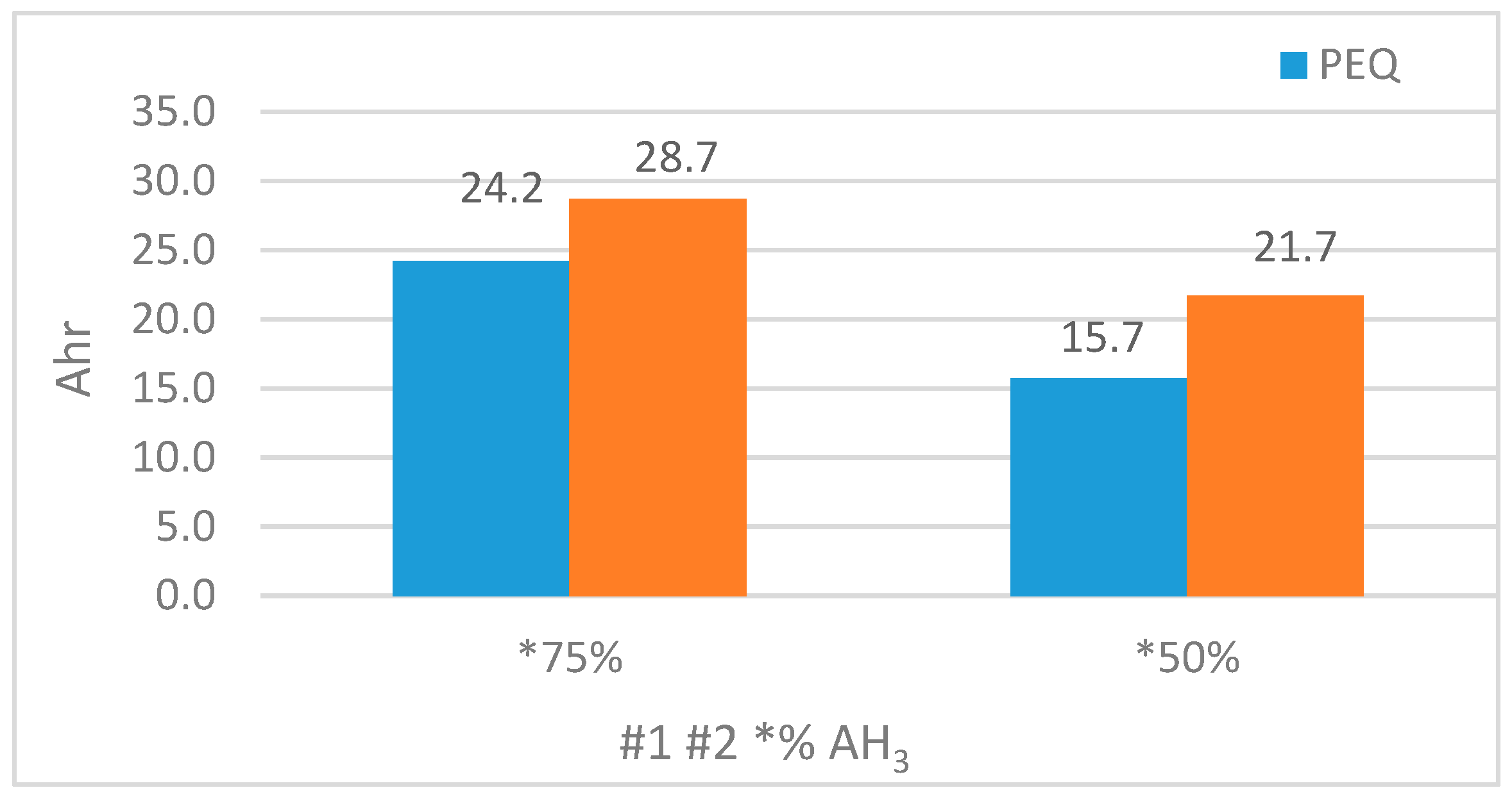
Next, a full discharge at ID = 7 Adc was done with the BEQ on, but the discharge capacity was only 21.73 Ah. This is considerably less that the calculated maximum of 27.29 Ah, which required an average AEQ current of 2.42 Adc. Therefore, the actual maximum value of 1.9 Adc is too low to achieve maximum capacity, but it is still 42.3% above the 15.27 Ah without the BEQ. The results are summarized in Table 1, and a comparison of the Ah capacities of the PEQ and BEQ are shown in Figure 9.
5. Summary
Large Li ion batteries such as those in EVs have expected lifetimes of close to 10 years, but as the batteries age, large variations in the cell capacity begin to appear. This becomes even more important for second life applications that employ used EV batteries for energy storage. Conventional PEQs and low current AEQs are typically only used as Voltage EQUs while the battery is inactive and do nothing to compensate for the loss in battery capacity due to a few weaker cells. This means that the battery discharge capacity is exactly equal to that of the weakest cell, and this indicates the need for a new class of EQUs called Capacity EQUs that operate while the battery is active, in order to provide a discharge capacity close to the average of the cells. Since these EQUs must transfer charge, only AEQs or AEQ hybrids can qualify.
However, a capacity EQU will never be adopted unless it is cost-effective, and this is difficult to achieve for AEQs that operate directly on each cell. The BEQ hybrid is a possible solution to this problem, and the calculations and test results indicate that it can provide a capacity close to the cell average at a reasonable cost. This EQU still uses a separate PEQ for each section, but since the cell variations for a section are much smaller than for the entire battery, the PEQ current rating and heat dissipation can be reduced. The calculation method shown here can be used for specific examples, and it provides a means to prepare the specifications for the AEQ portion of the BEQ.
Author Contributions
N.S.M. and T.S. conceived and designed the experiments; N.S.M., K.S. and T.S. performed the experiments; T.S. analyzed the data; N.S.M., K.S. and T.S. designed and built the test equipment and analysis tools; N.S.M., K.S. and T.S. wrote the paper.
Funding
This research was funded by the University of Toledo Rocket Fuel Fund Grant R-1258/17-02-W16.
Conflicts of Interest
The authors declare no conflict of interest. The funders had no role in the design of the study; in the collection, analyses, or interpretation of data; in the writing of the manuscript, or in the decision to publish the results.
Glossary
| Adc | DC Amps |
| Ah | Amp Hours |
| BEQ | Bilevel Equalizer |
| EQU | Equalizer |
| FET | Field Effect Transistor |
| h | Hours |
| I | Current |
| PEQ | Passive Equalizer |
| AEQ | Active Equalizer |
| T | Time |
| Vdc | DC Voltage |
References
- Second-Life Electric Vehicle Batteries 2019–2029. Available online: http://www.idtechex.com/research/reports/second-life-electric-vehicle-batteries-2019-2029-000626.asp (accessed on 3 March 2019).
- Li, H.; Alsolami, M.; Yang, S.; Alsmadi, Y.M.; Wang, J. Lifetime Test Design for Second-Use Electric Vehicles Batteries in Residential Applications. IEEE Trans. Sustain. Energy 2017, 8, 1736–1746. [Google Scholar] [CrossRef]
- Gohla-Neudecker, B.; Bowler, M.; Mohr, S. Battery 2nd Life: Leveraging the Sustainability Potential of EVs and Renewable Energy Grid Integration. In Proceedings of the 2015 International Conference on Clean Electrical Power (ICCEP), Taormina, Italy, 16–18 June 2015; pp. 311–318. [Google Scholar]
- Abdel-Monem, M.; Hegazy, O.; Omar, N.; Trad, K.; van den Bossche, P.; van Mierlo, J. Lithium-Ion Batteries: Comprehensive Technical Analysis of Second-Life Batteries for Smart Grid Applications. In Proceedings of the 2017 19th European Conference on Power Electronics and Applications (EPE’17 ECCE Europe), Warsaw, Poland, 11–14 September 2017. [Google Scholar]
- Linear Technology. LTC6804-1/LTC6804-2 Multicell Battery Monitors; Linear Technology Corporation: Milipitas, CA, USA, 2013. [Google Scholar]
- Kutkut, N.; Wiegman, H.; Divan, D.; Novotny, D. Design considerations for charge equalization of an electric vehicle battery system. IEEE Trans. Ind. Appl. 1999, 35, 96–103. [Google Scholar] [CrossRef]
- Stuart, T.A.; Zhu, W. Fast Equalization for Large Lithium Ion Batteries. IEEE Aerosp. Electron. Syst. Mag. 2009, 24, 27–31. [Google Scholar] [CrossRef]
- Gallardo-Lozano, J.; Romero-Cadaval, E.; Milanes-Montero, M.; Guerrero-Martinez, M. Battery Equalization Active Methods. J. Power Sources 2014, 246, 934–949. [Google Scholar] [CrossRef]
- Analog Devices. LTC3300-1 High Efficiency Bidirectional Multicell Battery Balancer; Linear Technology datasheet LT1213 REV B; Analog Devices: Norwood, MA, USA, 2013. [Google Scholar]
- Texas Instruments Incorporated. EM1401EVM User’s Guide; Texas Instruments Publication SNOU128; Texas Instruments Incorporated: Dallas, TX, USA, 2014. [Google Scholar]
- Zhang, D.-A.; Zhu, G.-R.; He, S.-J.; Qiu, S.; Ma, Y.; Wu, Q.-M.; Chen, W. Balancing Control Strategy for Li-Ion Batteries String Based on Dynamic Balanced Point. Energies 2015, 8, 1830–1847. [Google Scholar] [CrossRef] [Green Version]
- Lee, K.M.; Lee, S.W.; Choi, Y.G.; Kang, B. Active Balancing of Li-Ion Battery Cells Using Transformer as Energy Carrier. IEEE Trans. Ind. Electron. 2017, 64, 1251–1257. [Google Scholar] [CrossRef]
- Han, W.; Zhang, L.; Han, Y. Mathematical Modeling, Performance Analysis and Control of Battery Equalization Systems: Review and Recent Developments. In Advances in Battery Manufacturing, Service, and Management Systems, 1st ed.; John Wiley & Sons, Inc.: New York, NY, USA, 2017; pp. 281–298. [Google Scholar]
- Han, W.; Zou, C.; Zhou, C.; Zhang, L. Estimation of Cell SOC Evolution and System Performance in Module-based Battery Charge Equalization Systems. IEEE Trans. Smart Grid 2018. [Google Scholar] [CrossRef]
- Hu, X.; Zou, C.; Zhang, C.; Li, Y. Technological Developments in Batteries: A Survey of Principal Roles, Types, and Management Needs. IEEE Power Energy Mag. 2017, 15, 20–31. [Google Scholar] [CrossRef]
- Ouyang, Q.; Chen, J.; Zheng, J.; Fang, H. Optimal Cell-to-Cell Balancing Topology Design for Serially Connected Lithium-Ion Battery Packs. IEEE Trans. Sustain. Energy 2018, 9, 350–360. [Google Scholar] [CrossRef]
- Lim, C.-S.; Lee, K.-J.; Ku, N.-J.; Hyun, D.-S.; Kim, R.-Y. A Modularized Equalization Method Based on Magnetizing Energy for a Series Connected Lithium-Ion Battery String. IEEE Trans. Power Electron. 2014, 29, 1791–1799. [Google Scholar] [CrossRef]
- Park, H.S.; Kim, C.H.; Park, K.B.; Moon, G.W.; Lee, J.H. Design of a Charge Equalizer Based on Battery Modularization. IEEE Trans. Veh. Technol. 2009, 58, 3216–3223. [Google Scholar] [CrossRef]
- Kim, C.H.; Kim, M.Y.; Park, H.S.; Moon, G.W. A Modularized Two-Stage Charge Equalizer with Cell Selection Switches for Series Connected Lithium-Ion Battery String in an HEV. IEEE Trans. Power Electron. 2012, 27, 3764–3774. [Google Scholar] [CrossRef]
- Lin, X.; Stefanopoulou, A.G.; Li, Y.; Anderson, R.D. State of Charge Imbalance Estimation for Battery Strings under Reduced Voltage Sensing. IEEE Trans. Control Syst. Technol. 2015, 23, 1052–1062. [Google Scholar]
- Stuart, T.A. A Bilevel Equalizer for Battery Cell Charge Management. Patent WO 2017132529A1, 3 August 2017. [Google Scholar]
- Mubenga, S.; Linkous, Z.; Stuart, T. A Bilevel Equalizer for Large Lithium Ion Batteries. Batteries 2017, 3, 39. [Google Scholar] [CrossRef]
- Mubenga, N.; Linkous, Z.; Stuart, T. A Bilevel Equalizer for Lithium Ion Batteries. In Proceedings of the NAECON 2018, IEEE National Aerospace and Electronics Conference, Dayton, OH, USA, 23–26 July 2018. [Google Scholar]
Figure 1.
BEQ connections to a battery with 4 sections.

Figure 2.
PEQ connections to a cell.

Figure 3.
Basic inductive AEQ driver and waveforms. (a) Inductive AEQ driver connected to battery sections S1 and S2. (b) Inductor current, IL, and Q1 gate drive waveforms.
Figure 3.
Basic inductive AEQ driver and waveforms. (a) Inductive AEQ driver connected to battery sections S1 and S2. (b) Inductor current, IL, and Q1 gate drive waveforms.

Figure 4.
AEQ circuit for Examples 1 and 2. (a) Block diagram; and (b) inductor current example.

Figure 5.
AEQ flow diagram for Examples 1 and 2.

Figure 6.
Li ion battery with 24S-8P cells.

Figure 7.
BEQ laboratory prototype.

Figure 8.
AEQ flow diagram for Tests 1 and 2.

Figure 9.
The PEQ and BEQ Ah discharge capacities for Tests #1 and #2.


Table 1.
Calculated and measured results for Tests #1 and #2.
| Test Case | Calculated | Measured | |||||
|---|---|---|---|---|---|---|---|
| Test | AH3 | Ieq | AH | AH gain | Ieq | AH | AH Gain |
| # 1 No BEQ | 75% | n/a | 24 | n/a | n/a | 24.2 | n/a |
| #1 BEQ | 75% | 1.09 A | 29.92 | 24.7% | 1.9 A | 28.68 | 18.5% |
| # 2 No BEQ | 50% | n/a | 16 | n/a | n/a | 15.67 | n/a |
| #2 BEQ | 50% | 2.42 A | 27.29 | 70.6% | 1.9 A | 21.73 | 42.3% |
© 2019 by the authors. Licensee MDPI, Basel, Switzerland. This article is an open access article distributed under the terms and conditions of the Creative Commons Attribution (CC BY) license (http://creativecommons.org/licenses/by/4.0/).
Share and Cite
MDPI and ACS Style
Mubenga, N.S.; Sharma, K.; Stuart, T. A Bilevel Equalizer to Boost the Capacity of Second Life Li Ion Batteries. Batteries 2019, 5, 55. https://doi.org/10.3390/batteries5030055
AMA Style
Mubenga NS, Sharma K, Stuart T. A Bilevel Equalizer to Boost the Capacity of Second Life Li Ion Batteries. Batteries. 2019; 5(3):55. https://doi.org/10.3390/batteries5030055
Chicago/Turabian StyleMubenga, Ngalula Sandrine, Kripa Sharma, and Thomas Stuart. 2019. "A Bilevel Equalizer to Boost the Capacity of Second Life Li Ion Batteries" Batteries 5, no. 3: 55. https://doi.org/10.3390/batteries5030055
Note that from the first issue of 2016, this journal uses article numbers instead of page numbers. See further details here.