
Preparation of Composite Electrodes for All-Solid-State Batteries Based on Sulfide Electrolytes: An Electrochemical Point of View

 , , and
Abstract
:1. Introduction
2. Results and Discussion
3. Materials and Methods
3.1. Synthesis of Sulfide Solid Electrolytes
3.2. Preparation of Li2O-SiO2 (LS)-Coated NMC
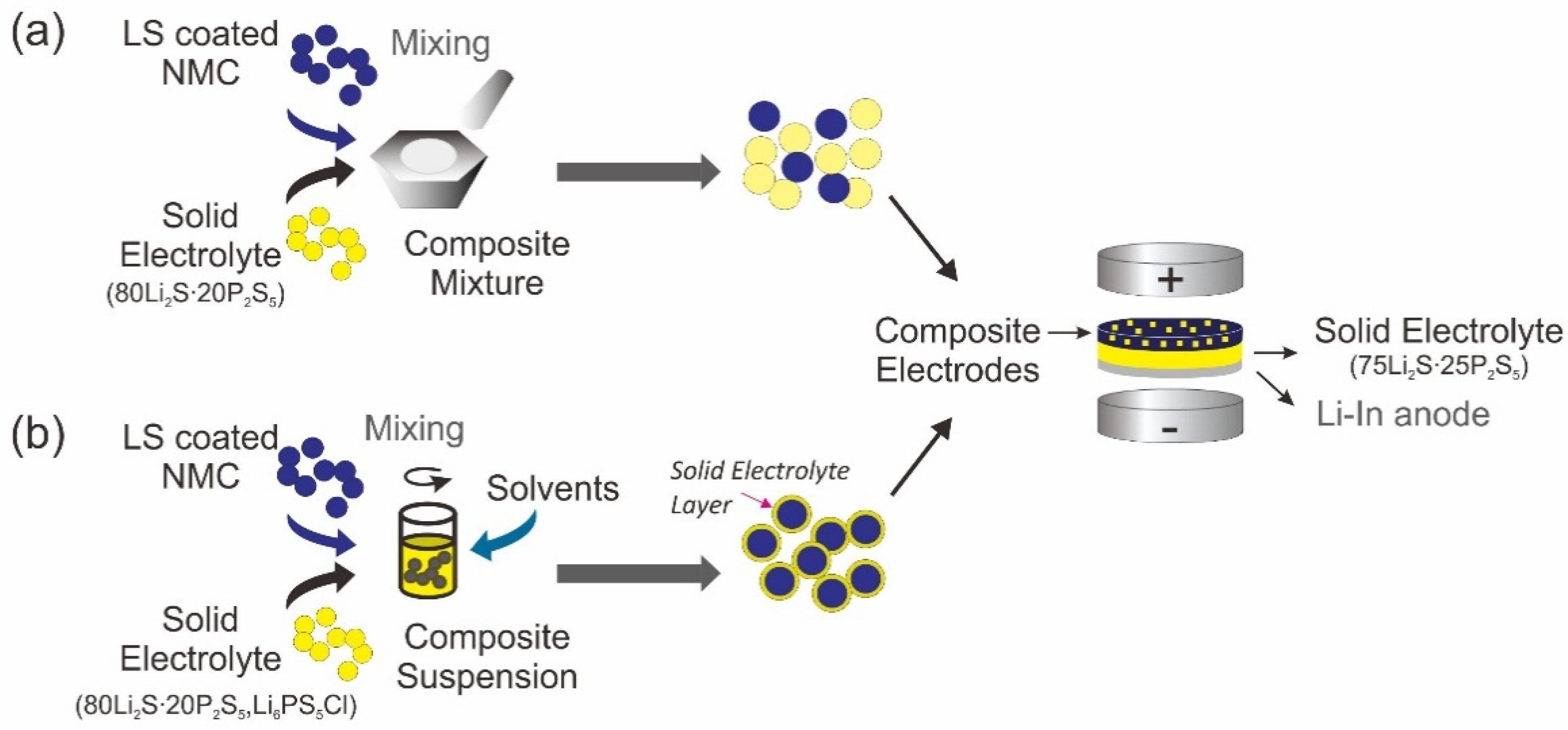
3.3. Preparation of Composite Electrodes
3.4. Assembly of All-Solid-State Batteries (ASSBs)
3.5. Characterization
4. Conclusions
Author Contributions
Funding
Institutional Review Board Statement
Informed Consent Statement
Acknowledgments
Conflicts of Interest
References
- Zhou, L.; Zhang, K.; Hu, Z.; Tao, Z.; Mai, L.; Kang, Y.M.; Chou, S.L.; Chen, J. Recent Developments on and Prospects for Electrode Materials with Hierarchical Structures for Lithium-Ion Batteries. Adv. Energy Mater. 2018, 8, 1–23. [Google Scholar] [CrossRef]
- Baster, D.; Paziak, P.; Zi, M.; Wazny, G.; Molenda, J. LiNi0.6 Co0.4-z TizO2-New cathode materials for Li-ion batteries. Solid State Ion. 2018, 320, 118–125. [Google Scholar] [CrossRef]
- Xiayin, Y.; Bingxin, H.; Jingyun, Y.; Gang, P.; Zhen, H.; Chao, G.; Deng, L.; Xiaoxiong, X. All-solid-state lithium batteries with inorganic solid electrolytes: Review of fundamental. Chin. Phys. B 2019, 25, 1–14. [Google Scholar]
- Deng, S.; Sun, Q.; Li, M.; Adair, K.; Yu, C.; Li, J.; Li, W.; Fu, J.; Li, X.; Li, R.; et al. Insight into cathode surface to boost the performance of solid-state batteries. Energy Storage Mater 2021, 35, 661–668. [Google Scholar] [CrossRef]
- Zheng, F.; Kotobuki, M.; Song, S.; Lai, M.O.; Lu, L. Review on solid electrolytes for all-solid-state lithium-ion batteries. J. Power Sources 2018, 389, 198–213. [Google Scholar] [CrossRef]
- Takada, K.; Ohta, N.; Zhang, L.; Xu, X.; Thi Hang, B.; Ohnishi, T.; Osada, M.; Sasaki, T. Interfacial phenomena in solid-state lithium battery with sulfide solid electrolyte. Solid State Ion. 2012, 225, 594–597. [Google Scholar] [CrossRef]
- Richards, W.D.; Miara, L.J.; Wang, Y.; Kim, J.C.; Ceder, G. Interface stability in solid-state batteries. Chem. Mater. 2016, 28, 266–273. [Google Scholar] [CrossRef]
- Sumita, M.; Tanaka, Y.; Ikeda, M.; Ohno, T. Charged and discharged states of cathode/sulfide electrolyte interfaces in all-solid-state lithium ion batteries. J. Phys. Chem. C 2016, 120, 13332–13339. [Google Scholar] [CrossRef]
- Sakuda, A.; Hayashi, A.; Tatsumisago, M. Interfacial observation between LiCoO2 electrode and Li2S–P2S5 solid electrolytes of all-solid-state lithium secondary batteries using transmission electron microscopy. Chem. Mater. 2010, 22, 949–956. [Google Scholar] [CrossRef]
- Kwak, H.W.; Park, Y.J. Cathode coating using LiInO2−LiI composite for stable sulfide-based all-solid-state batteries. Sci. Rep. 2019, 9, 8099. [Google Scholar] [CrossRef] [Green Version]
- Deng, S.; Sun, Y.; Li, X.; Ren, Z.; Liang, J.; Doyle-Davis, K.; Liang, J.; Li, W.; Banis, M.N.; Sun, Q.; et al. Eliminating the Detrimental Effects of Conductive Agents in Sulfide-Based Solid-State Batteries. ACS Energy Lett. 2020, 5, 1243–1251. [Google Scholar] [CrossRef]
- Wu, J.; Shen, L.; Zhang, Z.; Liu, G.; Wang, Z.; Zhou, D.; Wan, H.; Xu, X.; Yao, X. All-Solid-State Lithium Batteries with Sulfide Electrolytes and Oxide Cathodes. Electrochem. Energy Rev. 2021, 4, 101135. [Google Scholar] [CrossRef]
- Woo, J.H.; Trevey, J.E.; Cavanagh, A.S.; Choi, Y.S.; Kim, S.C.; George, S.M.; Oh, K.H.; Lee, S.-H. Nanoscale interface modification of LiCoO2 by Al2O3 atomic layer deposition for solid-state Li batteries. J. Electrochem. Soc. 2012, 159, A1120–A1124. [Google Scholar] [CrossRef]
- Li, X.; Liang, M.; Sheng, J.; Song, D.; Zhang, H.; Shi, X.; Zhang, L. Constructing double buffer layers to boost electrochemical performances of NCA cathode for ASSLB. Energy Storage Mater. 2019, 18, 100–106. [Google Scholar] [CrossRef]
- Yubuchi, S.; Ito, Y.; Matsuyama, T.; Hayashi, A.; Tatsumisago, M. 5 V class LiNi0.5Mn1.5O4 positive electrode coated with Li3PO4 thin film for all-solid-state batteries using sulfide solid electrolyte. Solid State Ion. 2016, 285, 79–82. [Google Scholar] [CrossRef]
- Kim, J.; Kim, M.; Noh, S.; Lee, G.; Shin, D. Enhanced electrochemical performance of surface modified LiCoO2 for all-solid-state lithium batteries. Ceram. Int. 2016, 42, 2140–2146. [Google Scholar] [CrossRef]
- Miura, A.; Rosero-Navarro, N.C.; Sakuda, A.; Tadanaga, K.; Phuc, N.H.H.; Matsuda, A.; Machida, N.; Hayashi, A.; Tatsumisago, M. Liquid-phase syntheses of sulfide electrolytes for all-solid-state lithium battery. Nat. Rev. Chem. 2019, 3, 189–198. [Google Scholar] [CrossRef]
- Tadanaga, K.; Rosero-Navarro, N.C.; Miura, A. Wet Chemical Processes for the Preparation of Composite Electrodes in All-Solid-State Lithium Battery. In Next Generation Batteries: Realization of High Energy Density Rechargeable Batteries; Kanamura, K., Ed.; Springer: Singapore, 2021; pp. 85–92. [Google Scholar]
- Teragawa, S.; Aso, K.; Tadanaga, K.; Hayashi, A.; Tatsumisago, M. Liquid-phase synthesis of a Li3PS4 solid electrolyte using N-methylformamide for all-solid-state lithium batteries. J. Mater. Chem. A 2014, 2, 5095–5099. [Google Scholar] [CrossRef]
- Yubuchi, S.; Teragawa, S.; Aso, K.; Tadanaga, K.; Hayashi, A.; Tatsumisago, M. Preparation of high lithium-ion conducting Li6PS5Cl solid electrolyte from ethanol solution for all-solid-state lithium batteries. J. Power Sources 2015, 293, 941–945. [Google Scholar] [CrossRef] [Green Version]
- Park, K.H.; Oh, D.Y.; Choi, Y.E.; Nam, Y.J.; Han, L.L.; Kim, J.Y.; Xin, H.L.; Lin, F.; Oh, S.M.; Jung, Y.S. Solution-processable glass LiI-Li4SnS4 superionic conductors for all-solid-state Li-ion batteries. Adv. Mater. 2016, 28, 1874–1883. [Google Scholar] [CrossRef]
- Choi, Y.E.; Park, K.H.; Kim, D.H.; Oh, D.Y.; Kwak, H.R.; Lee, Y.G.; Jung, Y.S. Coatable Li4SnS4 Solid Electrolytes Prepared from Aqueous Solutions for All-Solid-State Lithium-Ion Batteries. ChemSusChem 2017, 10, 2605–2611. [Google Scholar] [CrossRef] [PubMed]
- Chida, S.; Miura, A.; Rosero-Navarro, N.C.; Higuchi, M.; Phuc, N.H.H.; Muto, H.; Matsuda, A.; Tadanaga, K. Liquid-phase synthesis of Li6PS5Br using ultrasonication and application to cathode composite electrodes in all-solid-state batteries. Ceram. Int. 2017, 44, 742–746. [Google Scholar] [CrossRef] [Green Version]
- Yao, X.; Liu, D.; Wang, C.; Long, P.; Peng, G.; Hu, Y.-S.; Li, H.; Chen, L.; Xu, X. High-Energy All-Solid-State Lithium Batteries with Ultralong Cycle Life. Nano Lett. 2016, 16, 7148–7154. [Google Scholar] [CrossRef] [PubMed]
- Zhang, Q.; Mwizerwa, J.P.; Wan, H.L.; Cai, L.T.; Xu, X.X.; Yao, X.Y. Fe3S4@Li7P3S11 nanocomposites as cathode materials for all-solid-state lithium batteries with improved energy density and low cost. J. Mater. Chem. A 2017, 5, 23919–23925. [Google Scholar] [CrossRef]
- Xu, R.C.; Wang, X.L.; Zhang, S.Z.; Xia, Y.; Xia, X.H.; Wu, J.B.; Tu, J.P. Rational coating of Li7P3S11 solid electrolyte on MoS2 electrode for all-solid-state lithium ion batteries. J. Power Sources 2018, 374, 107–112. [Google Scholar] [CrossRef]
- Famprikis, T.; Canepa, P.; Dawson, J.A.; Islam, M.S.; Masquelier, C. Fundamentals of inorganic solid-state electrolytes for batteries. Nat. Mater. 2019, 18, 1278–1291. [Google Scholar] [CrossRef]
- Zhao, E.; Liu, X.; Zhao, H.; Xiao, X.; Hu, Z. Ion conducting Li2SiO3-coated lithium-rich layered oxide exhibiting high rate capability and low polarization. Chem. Commun. 2015, 51, 9093–9096. [Google Scholar] [CrossRef]
- Sakuda, A.; Kitaura, H.; Hayashi, A.; Tadanaga, K.; Tatsumisago, M. Improvement of High-Rate Performance of All-Solid-State Lithium Secondary Batteries Using LiCoO2 Coated with Li2O-SiO2 Glasses. Electrochem. Solid-State Lett. 2007, 11, A1. [Google Scholar] [CrossRef]
- Ohta, N.; Takada, K.; Sakaguchi, I.; Zhang, L.; Ma, R.; Fukuda, K.; Osada, M.; Sasaki, T. LiNbO3-coated LiCoO2 as cathode material for all solid-state lithium secondary batteries. Electrochem. Commun. 2007, 9, 1486–1490. [Google Scholar] [CrossRef]
- Hirschorn, B.; Orazem, M.E.; Tribollet, B.; Vivier, V.; Frateur, I.; Musiani, M. Electrochimica Acta Determination of effective capacitance and film thickness from constant-phase-element parameters. Electrochim. Acta J. 2010, 55, 6218–6227. [Google Scholar] [CrossRef]
- Calpa, M.; Rosero-Navarro, N.C.; Miura, A.; Tadanaga, K. Electrochemical performance of bulk-type all-solid-state batteries using small-sized Li7P3S11 solid electrolyte prepared by liquid phase as the ionic conductor in the composite cathode. Electrochim. Acta 2019, 296, 473–480. [Google Scholar] [CrossRef]
- Ohno, S.; Bernges, T.; Buchheim, J.; Duchardt, M.; Hatz, A.-K.; Kraft, M.A.; Kwak, H.; Santhosha, A.L.; Liu, Z.; Minafra, N.; et al. How Certain Are the Reported Ionic Conductivities of Thiophosphate-Based Solid Electrolytes? An Interlaboratory Study. ACS Energy Lett. 2020, 5, 910–915. [Google Scholar] [CrossRef] [Green Version]
- Koerver, R.; Aygün, I.; Leichtweiß, T.; Dietrich, C.; Zhang, W.; Binder, J.O.; Hartmann, P.; Zeier, W.G.; Janek, J. Capacity Fade in Solid-State Batteries: Interphase Formation and Chemomechanical Processes in Nickel-Rich Layered Oxide Cathodes and Lithium Thiophosphate Solid Electrolytes. Chem. Mater. 2017, 29, 5574–5582. [Google Scholar] [CrossRef]
- Schwietert, T.K.; Arszelewska, V.A.; Wang, C.; Yu, C.; Vasileiadis, A.; de Klerk, N.J.J.; Hageman, J.; Hupfer, T.; Kerkamm, I.; Xu, Y.; et al. Clarifying the relationship between redox activity and electrochemical stability in solid electrolytes. Nat. Mater. 2020, 19, 428–435. [Google Scholar] [CrossRef] [PubMed] [Green Version]
- Tan, D.H.S.; Wu, E.A.; Nguyen, H.; Chen, Z.; Marple, M.A.T.; Doux, J.M.; Wang, X.; Yang, H.; Banerjee, A.; Meng, Y.S. Elucidating Reversible Electrochemical Redox of Li6PS5Cl Solid Electrolyte. ACS Energy Lett. 2019, 4, 2418–2427. [Google Scholar] [CrossRef]
- Noh, H.-J.; Youn, S.; Yoon, C.S.; Sun, Y.-K. Comparison of the structural and electrochemical properties of layered Li[NixCoyMnz]O2 (x = 1/3, 0.5, 0.6, 0.7, 0.8 and 0.85) cathode material for lithium-ion batteries. J. Power Sources 2013, 233, 121–130. [Google Scholar] [CrossRef]
- Zhang, Q.; Cao, D.; Ma, Y.; Natan, A.; Aurora, P.; Zhu, H. Sulfide-Based Solid-State Electrolytes: Synthesis, Stability, and Potential for All-Solid-State Batteries. Adv. Mater. 2019, 31, 1901131. [Google Scholar] [CrossRef]
- Lou, S.; Liu, Q.; Zhang, F.; Liu, Q.; Yu, Z.; Mu, T.; Zhao, Y.; Borovilas, J.; Chen, Y.; Ge, M.; et al. Insights into interfacial effect and local lithium-ion transport in polycrystalline cathodes of solid-state batteries. Nat. Commun. 2020, 11, 1–10. [Google Scholar] [CrossRef] [PubMed]
- Bisquert, J.; Garcia-belmonte, G.; Bueno, P.; Longo, E.; Bulhoes, L.O. Impedance of constant phase element (CPE)-blocked diffusion in film electrodes. J. Electroanal. Chem. 1998, 452, 229–234. [Google Scholar] [CrossRef]
- Bisquert, J.; Garcia-Belmonte, G.; Fabregat-Santiago, F.; Bueno, P.R. Theoretical models for ac impedance of finite diffusion layers exhibiting low frequency dispersion. J. Electroanal. Chem. 1999, 475, 152–163. [Google Scholar] [CrossRef]
- Jung, R.; Metzger, M.; Maglia, F.; Stinner, C.; Gasteiger, H.A. Oxygen Release and Its Effect on the Cycling Stability of LiNixMnyCozO2 (NMC) Cathode Materials for Li-Ion Batteries. J. Electrochem. Soc. 2017, 164, A1361–A1377. [Google Scholar] [CrossRef]
- Hayashi, A.; Hama, S.; Morimoto, H.; Tatsumisago, M.; Minami, T. Preparation of Li2S-P2S5 amorphous solid electrolytes by mechanical milling. J. Am. Ceram. Soc. 2004, 84, 477–479. [Google Scholar] [CrossRef]
- Rosero-Navarro, N.C.; Kajiura, R.; Jalem, R.; Tateyama, Y.; Miura, A.; Tadanaga, K. Significant Reduction in the Interfacial Resistance of Garnet-Type Solid Electrolyte and Lithium Metal by a Thick Amorphous Lithium Silicate Layer. ACS Appl. Energy Mater. 2020, 3, 5533–5541. [Google Scholar] [CrossRef]
- Sakuda, A.; Yamamoto, M.; Nose, M.; Kato, A.; Hayashi, A.; Tatsumisago, M. Mechanical properties of sul fi de glasses in all-solid-state batteries. J. Ceram. Soc. Jpn. 2018, 126, 719–727. [Google Scholar] [CrossRef] [Green Version]


| Sulfide Solid Electrolyte Composition | Process | Ionic Conductivity S∙cm−1 at 25 °C |
|---|---|---|
| 80Li2S∙20P2S5 | MM 1 | 9 × 10⁻⁵ |
| 80Li2S∙20P2S5 | SP 2 | 5 × 10⁻⁷ |
| Li6PS5Cl (LPSCl) | SP 2 | 4 × 10⁻⁵ |
| Cathode Composite | RSE (Ω) | Ceff.SE (µF) | TSE (s) | RSE.GB (Ω) | Ceff.SE.GB (µF1) | TSE.GB (s) | RSE/Cat (Ω) | Ceff.SE/Cat (µF) | TSE/Cat (s) | RSE/An (Ω) | Ceff.SE/An (µF) | TSE/An (s) | GOF |
|---|---|---|---|---|---|---|---|---|---|---|---|---|---|
| SIMPLE MIXTURE | |||||||||||||
| Uncoated | 277.0 | - | - | 57.8 | 0.7 | 4 × 10⁻⁵ | 797.0 | 1.3 | 1 × 10⁻³ | 245.2 | 365.9 | 0.09 | 2 × 10⁻⁵ |
| B1 | 244.5 | 2 × 10⁻⁴ | 5 × 10⁻⁸ | 49.1 | 1.2 | 6 × 10⁻⁵ | 543.0 | 1.4 | 8 × 10⁻⁴ | 164.1 | 1342.8 | 0.22 | 6 × 10⁻⁵ |
| B2 | 167.0 | 3 × 10⁻⁴ | 5 × 10⁻⁸ | 87.2 | 2.1 | 2 × 10⁻⁴ | 858.4 | 2.0 | 2 × 10⁻³ | 179.3 | 5381.6 | 0.96 | 6 × 10⁻⁵ |
| B3 | 195.1 | 2 × 10⁻⁴ | 3 × 10⁻⁸ | 36.9 | 1.7 | 6 × 10⁻⁵ | 525.8 | 2.7 | 1 × 10⁻³ | 240.9 | 168.1 | 0.04 | 8 × 10⁻⁶ |
| SOLUTION PROCESS | |||||||||||||
| Uncoated | 189.0 | 3 × 10⁻⁴ | 5 × 10⁻⁸ | 113.7 | 0.8 | 9 × 10⁻⁵ | 295.9 | 2.6 | 8 × 10⁻⁴ | 81.0 | 732.1 | 0.06 | 3 × 10⁻⁵ |
| B1 | 253.1 | - | - | 86.4 | 0.1 | 5 × 10⁻⁶ | 191.9 | 1.2 | 2 × 10⁻⁴ | 108.9 | 253.0 | 0.03 | 2 × 10⁻⁵ |
| B2 | 250.8 | 3 × 10⁻⁴ | 6 × 10⁻⁸ | 114.8 | 0.6 | 6 × 10⁻⁵ | 195.1 | 3.7 | 7 × 10⁻⁴ | 128.2 | 317.7 | 0.04 | 4 × 10⁻⁵ |
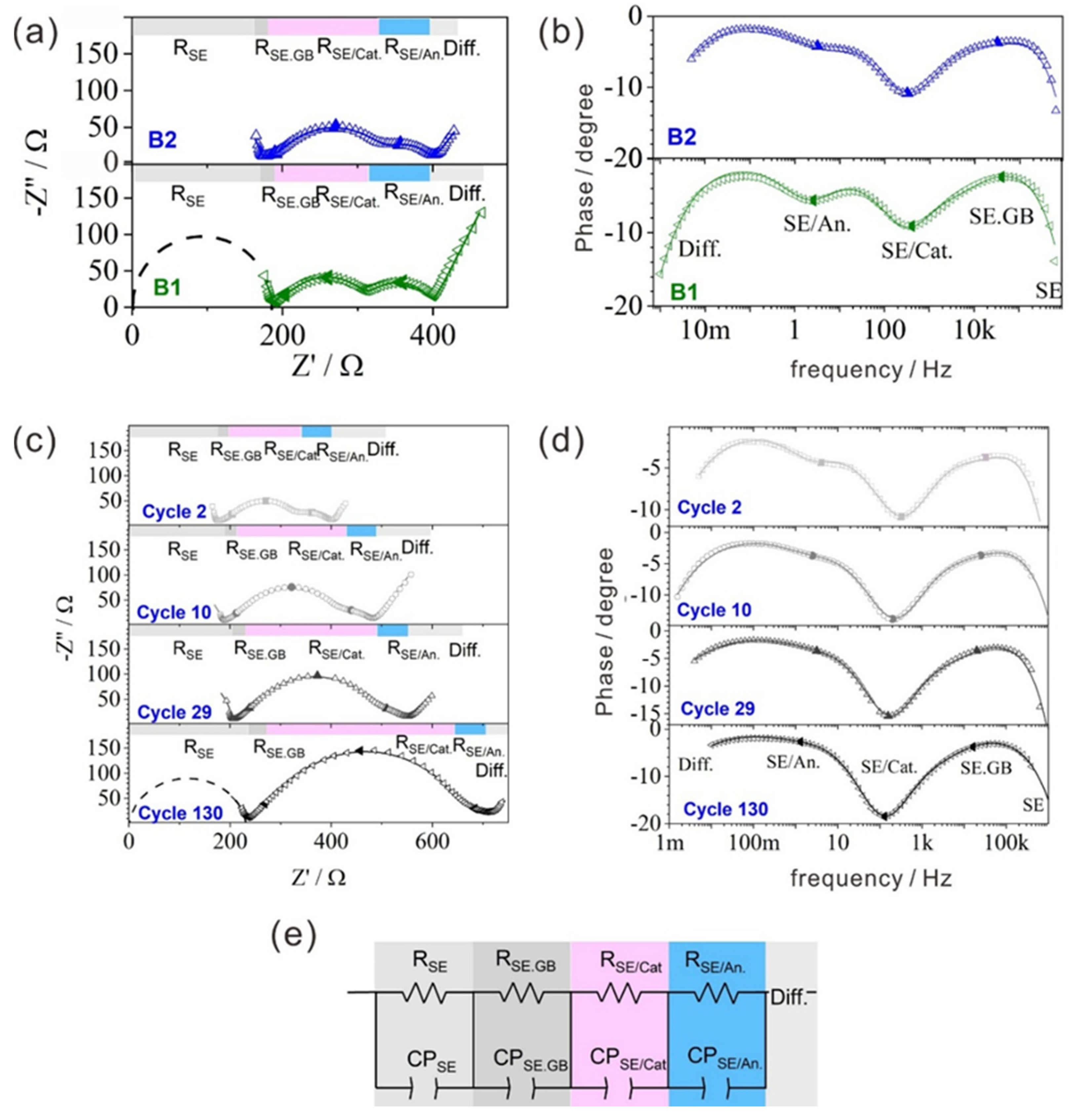
| Electrode Composite– Cycle | RSE (Ω) | Ceff.SE (µF) | TSE (s) | RSE.GB (Ω) | Ceff.SE.GB (µF) | TSE.GB (s) | RSE/Cat (Ω) | Ceff.SE/Cat (µF) | TSE/Cat (s) | RSE/An (Ω) | Ceff.SE/An (µF) | TSE/An (s) | TDiff (s) | GOF |
|---|---|---|---|---|---|---|---|---|---|---|---|---|---|---|
| B1–2 | 186.6 | 3 × 10⁻⁴ | 5 × 10⁻⁸ | 19.4 | 1.4 | 3 × 10⁻⁵ | 107.0 | 3.7 | 4 × 10⁻⁴ | 86.0 | 907.7 | 0.08 | 6 × 10⁶ | 6 × 10⁻⁵ |
| B2–2 | 171.6 | 3 × 10⁻⁴ | 5 × 10⁻⁸ | 19.4 | 0.4 | 7 × 10⁻⁶ | 150.2 | 2.0 | 3 × 10⁻⁴ | 57.4 | 1124.2 | 0.07 | 4 × 10⁶ | 3 × 10⁻⁵ |
| B2–10 | 184.0 | 2 × 10⁻⁴ | 3 × 10⁻⁸ | 23.9 | 0.5 | 1 × 10⁻⁵ | 214.9 | 2.3 | 5 × 10⁻⁴ | 61.1 | 1263.3 | 0.08 | 5 × 10⁶ | 2 × 10⁻⁵ |
| B2–29 | 202.0 | 3 × 10⁻⁴ | 5 × 10⁻⁸ | 37.6 | 0.7 | 3 × 10⁻⁵ | 252.6 | 3.3 | 8 × 10⁻⁴ | 56.6 | 1123.6 | 0.06 | 2 × 10⁷ | 3 × 10⁻⁵ |
| B2–130 | 231.9 | 2 × 10⁻⁴ | 4 × 10⁻⁸ | 50.0 | 1.2 | 6 × 10⁻⁵ | 379.0 | 3.3 | 1 × 10⁻³ | 52.3 | 2659.2 | 0.14 | 5 × 10⁷ | 1 × 10⁻⁵ |
Publisher’s Note: MDPI stays neutral with regard to jurisdictional claims in published maps and institutional affiliations. |
© 2021 by the authors. Licensee MDPI, Basel, Switzerland. This article is an open access article distributed under the terms and conditions of the Creative Commons Attribution (CC BY) license (https://creativecommons.org/licenses/by/4.0/).
Share and Cite
Giraldo, S.; Nakagawa, K.; Vásquez, F.A.; Fujii, Y.; Wang, Y.; Miura, A.; Calderón, J.A.; Rosero-Navarro, N.C.; Tadanaga, K. Preparation of Composite Electrodes for All-Solid-State Batteries Based on Sulfide Electrolytes: An Electrochemical Point of View. Batteries 2021, 7, 77. https://doi.org/10.3390/batteries7040077
Giraldo S, Nakagawa K, Vásquez FA, Fujii Y, Wang Y, Miura A, Calderón JA, Rosero-Navarro NC, Tadanaga K. Preparation of Composite Electrodes for All-Solid-State Batteries Based on Sulfide Electrolytes: An Electrochemical Point of View. Batteries. 2021; 7(4):77. https://doi.org/10.3390/batteries7040077
Chicago/Turabian StyleGiraldo, Sara, Koki Nakagawa, Ferley A. Vásquez, Yuta Fujii, Yongming Wang, Akira Miura, Jorge A. Calderón, Nataly C. Rosero-Navarro, and Kiyoharu Tadanaga. 2021. "Preparation of Composite Electrodes for All-Solid-State Batteries Based on Sulfide Electrolytes: An Electrochemical Point of View" Batteries 7, no. 4: 77. https://doi.org/10.3390/batteries7040077