


Nanostructured Manganese Dioxide for Hybrid Supercapacitor Electrodes

Departamento de Química Orgánica e Inorgánica, Facultad de Ciencia y Tecnología, Universidad del País Vasco (UPV/EHU), Barrio Sarriena s/n, 48940 Leioa, Spain
*
Authors to whom correspondence should be addressed.
Batteries 2022, 8(12), 263; https://doi.org/10.3390/batteries8120263
Submission received: 12 October 2022
/
Revised: 9 November 2022
/
Accepted: 16 November 2022
/
Published: 30 November 2022
(This article belongs to the Special Issue Feature Papers to Celebrate the First Impact Factor of Batteries)
Abstract
:Hybrid supercapacitors, as emerging energy storage devices, have gained much attention in recent years due to their high energy density, fast charge/discharge and long cyclabilities. Among the wide range of systems covered by this topic, low cost, environmental friendliness and high power provide MnO2 with great characteristics to be a competitive candidate. The present work reports a hybrid aqueous supercapacitor system using a commercial activated carbon as the negative electrode and a synthesized manganese dioxide as the positive electrode. Two manganese dioxide polymorphs (α-MnO2 and δ-MnO2) were tested in different neutral and basic aqueous electrolytes. In this way, full cell systems that reached an energy density of 15.6 Wh kg−1 at a power density of 1 kW kg−1 were achieved. The electrode–electrolyte combination explored in this study exhibits excellent performance without losing capacity after 5000 charge/discharge cycles, leading to a promising approach towards more sustainable, high-performance energy storage systems.
1. Introduction
One of the most critical challenges to overcoming the increasing environmental problems as well as the fast consumption of coal, gas and oil, is the deployment of ecological and consistent energy sources. However, renewable energy sources do not produce energy around the clock; thus, to be effectively utilized they require cheap, sustainable and efficient energy storage technologies [1,2]. For the above reasons, energy storage systems are a hot topic at the moment, attracting the attention of very varied fields of science, and benefiting from innovative techniques and multiple approaches to improve them [3,4]. Although most of the attention is focused on the use of batteries, especially lithium-ion batteries, but also electrochemical capacitors or supercapacitors (SCs), other emerging technologies such as sodium-ion batteries also need to be considered in this pool. Due to their fast charge and discharge rates, high power density and long-term cycling stability, SCs can be effectively combined with batteries, or even replace them, to design a custom-made solution [5,6]. These properties make SCs widely used devices in electric vehicles, military equipment, uninterruptible power supplies and many other applications that require high power input [7,8,9].
Based on the working mechanism of the electrodes, SCs can be classified in two main categories: electrical double-layer capacitors (EDLCs) and pseudocapacitors (PCs). The former rely on the electrosorption of electrolyte ions on the surface of the electrode to accumulate charge in the electrode–electrolyte interface [10]. Therefore, EDLC electrodes are generally made of carbon-based materials because of their large specific surface area (SSA), excellent electrical conductivity, and good electrochemical and mechanical stability [11,12,13]. Activated carbons (ACs) are usually selected due to their high porosity and large SSA (~1000–2500 m2 g−1) [14,15,16,17]. However, it is known that large surface area does not always translate into high capacitance values, and ultimately, energy, but pore size also plays an important role [18,19,20]. Nevertheless, despite their high specific power and long lifetime, the specific energy of EDLCs is limited by the lack of bulk charge storage (10–300 F g−1) [21,22].
On the other hand, PCs undergo fast and reversible Faradaic redox reactions that occur on the electrode surface during cycling [23,24,25]. Yet, when switching to PCs the reaction kinetics are slower and the electrical conductivity is lower, which translates into lower power output. Therefore, pseudocapacitors are usually focused to work at higher capacitances but in slightly higher charge/discharge times [26,27]. The PCs are generally fabricated using transition metal oxides (TMOs) and hydroxides such as Ni(OH)2, V2O5, Co3O4, NiO, Co(OH)2, etc., due to the ease of synthesizing them as nanoparticles, leading to a high porosity and SSA, and their ability to change between more than one oxidation state [28,29,30,31,32]. RuO2 has been widely studied because it possesses one of the highest electronic conductivity and theoretical capacitance of around 1450 F g−1 [33]. However, as it is quite non-abundant and expensive, researchers have been studying alternative compounds [34].
Among all of the candidates, MnO2 has proven to be one of the most promising materials because it is cheap, non-toxic, abundant and it also has a high theoretical specific capacitance (1370 F g−1) [35]. Contrary to other pseudocapacitive systems such as Co3O4 or NiO, in aqueous electrolyte MnO2 shows a full working potential window of ~1 V, achieving higher energy densities [36]. Nonetheless, as in other TMOs, due to its low conductivity (10−7–10−3 S cm−1), the capacitance becomes greatly reduced with increasing mass of the electrode, leading to practical values of ~250 F g−1 [36,37,38,39,40]. However, the implementation of high conductive additives such as Au, carbonaceous materials or conductive polymers, can successfully overcome this problem [41,42,43]. Other approaches have also been tested in order to deal with the poor conductivity of this material. Nanostructuring the electrodes is one of these promising methods because it produces a larger electrode–electrolyte interface, which enhances surface charge storage and it also obviates the low conductivity because of the short diffusion pathways of the nanostructure [24].
MnO2 can be easily synthesized in different polymorphs with different electrochemical performances. Some of the most remarkable ones are α-, β-, and γ-MnO2, in which the electron transfer is facilitated by its two-dimensional tunneling structure. The layered structure of δ-MnO2 favours the cation intercalation/deintercalation processes, giving rise to an excellent performance as an electrode material [24,44]. Reactions for surface and bulk charge storage are shown in Equations (1) and (2), respectively [28,45,46]:
where etc. Another way to deal with the low conductivity of MnO2 is its deposition onto a conductive substrate. This well-studied method has produced very good results, increasing the gravimetric capacitance to >400 F g−1 [47]. Actually, when the deposited film reaches the-tens-of-nanometer scale, the capacitances next to the theoretical value have been measured (~1250 F g−1) [24]. Still, the areal mass loading is significantly low, which leads to a deficient areal energy density. In addition, the manufacturing costs of the substrate as well as the thin layer deposition technique make this approach difficult to execute for practical applications [24]. Therefore, even if thin layer deposition and other approaches such as doping may be useful ways to deal with the low conductivity, the rational addition of highly conductive carbonaceous materials is a more affordable way to obtain easily scalable electrodes reaching ~400 F g−1 [24,28,48,49].
(MnO2)surface + A+ + e− ↔ MnOOAsurface
MnO2 + A+ + e− ↔ MnOOA
Since the properties of the electrode materials are crucial for the performance of the SCs, not only the material choice, but also the cell design is critical for an optimal operation. In this regard, much attention has been devoted to hybrid systems that operate with an EDLC electrode and a pseudocapacitive or battery-type electrode. These hybrid systems are designed in order to benefit from the advantages of each type of electrode, counteracting their individual weaknesses. Hybrid systems can also make use of the different potential windows of the electrodes, and thus increase the operation voltage of the cell, enhancing the overall energy density [50].
In the present report, an aqueous hybrid SC system is proposed, which works with an EDCL-type negative electrode made of an AC and a PC-type MnO2/carbon black composite positive electrode. MnO2 was synthesized in two different polymorphs, the previously mentioned α-MnO2 and δ-MnO2 phases, while the AC was commercial. The MnO2 and AC electrodes were characterized in three different aqueous electrolytes in order to choose the best combination to build a full hybrid cell. The three chosen aqueous electrolytes were 1 M KOH, 0.5 M Na2SO4 and 0.5 M Na2SO4 + 0.2 mM MnSO4. This work aims to compete with the more common metal–ion hybrids, while benefiting from the stability, safety, and low material and manufacturing cost of aqueous systems. The nanostructured MnO2 used as an electrode-active material, obtained by a one-step hydrothermal synthesis, offers an effective, more affordable alternative to the current state-of-the-art pseudocapacitive materials in the literature. Taken together with the choice of the electrolytes explored here, the proposed system aims to be as sustainable, safe and economical as possible.
2. Materials and Methods
2.1. Synthesis and Physical-Chemical Characterization of MnO2 Samples
KMnO4 (0.022 mol, Probus) was reduced with ethylene glycol (0.009 mol, Panreac) in distilled water (200 mL) at room temperature following the synthesis route proposed by Ragupathy et al. The mixture was stirred for 20 min and then MnO2 was vacuum filtered as a brown solid. After that, it was kept in a furnace at 60 °C until the next day, when the product was ground until it was a powder [51]. The obtained product was heat treated at different temperatures, i.e., 100, 200, 300, 400, 500 and 600 °C in a furnace.
Phase identification of the samples was carried out by X-ray diffraction, XRD (Panalytical X’Pert PRO) between 5 and 70° (2). Raman spectra were obtained using a Renishaw InVia spectrometer (785 nm wavelength, <1.5 mW power). The compositional characterization of the samples was carried out by thermogravimetric analysis, TGA (Ar, 5 °C/min until 800 °C, Netzsch STA 449) and inductively coupled plasma-atomic emission spectroscopy, ICP-AES (Agilent Technologies 5100, Agilent Technologies, Santa Clara, CA, USA). The morphology of the samples was studied by scanning electron microscopy, SEM (JEOL JSM-7000F, JEOL Ltd., Tokyo, Japan). The homogeneity of the samples was observed by energy-dispersive X-ray spectroscopy, EDX, mapping analysis (Carl Zeiss EVO-40 with Oxford Instruments X-Max, Carl Zeiss, Baden-Württemberg, Germany). The SSA values were estimated by applying the Brunauer–Emmett–Teller theory, BET, to the isotherms obtained from nitrogen adsorption/desorption measurements (0 and 273 K, Quantachrome AutosorbIQ, Anton Paar GmbH, Graz, Austria). Previous degasification was performed at 80 °C for 3 h and under 10−4 bar vacuum.
2.2. Preparation of Electrodes
Positive electrode composition was 70 wt% MnO2, 20 wt% conductive carbon black (Timcal Super 65) and 10 wt% polytetrafluoroethylene, PTFE (60 wt% dispersion in H2O, Sigma-Aldrich, St. Louis, MO, USA). Negative electrode composition was 90 wt% commercial activated carbon (SSA 1600 m2 g−1, NORIT DLC Super 30, Sigma-Aldrich, St. Louis, MO, USA) and 10 wt% PTFE. The purpose of adding carbon black to the active material was to enhance its conductivity to achieve a better electrochemical performance, while PTFE was the binder, which brings plasticity to the composite material. The mixtures were drenched in EtOH and blended until gaining enough plasticity to make a black film (~150 μm thickness). After letting the film dry in a vacuum oven at 80 °C for 12 h, it was cut into 11 mm diameter circles, which were weighted and labelled to be used as electrodes afterwards.
2.3. Electrochemical Characterization
Before the electrochemical characterization of the hybrid system, both positive (MnO2) and negative (AC) electrodes were tested in Swagelok®-type 3-electrode cells (Swagelok®, Solon, OH, USA) using an oversized AC counter electrode and a Ag/AgCl (3 M KCl, Metrohm, Herisau, Switzerland) reference electrode. Glass microfiber (GF/A, Whatman, Maidstone, UK) served as a separator. The systems were tested using cyclic voltammetry, CV (BioLogic VMP3, BioLogic, Orlando, FL, USA) at 5, 10, 20, 50, 100 and 200 mV s−1 sweep rates. Three aqueous electrolytes were tested, 0.5 M Na2SO4 (referred to in this work as just Na2SO4), 1 M KOH (hereinafter referred to as KOH) and 0.5 M Na2SO4 + 0.2 mM MnSO4 (hereinafter referred to as Na2SO4 + MnSO4). The latter electrolyte was chosen because the addition of 0.2–1 mM Mn2+ into Na2SO4 electrolyte had proven to improve the electrochemical response of MnO2 electrodes by avoiding the Mn2+ dissolution [52]. Final hybrid systems were tested in Swagelok®-type 2-electrode cells (Swagelok®, Solon, OH, USA) by CV at 5, 10, 20, 50, 100 and 200 mV s−1 and galvanostatic charge/discharges, GA, at 0.1, 0.5, 1, 2, 5, 7, 10 and 15 A g−1 current densities, calculated in terms of the mass of both electrodes. Finally, with the purpose of investigating the cyclic stability of the proposed system, 5000 GA cycles were carried out at a current density of 1 A g−1.
3. Results and Discussion
3.1. Structural Characterization of MnO2 Composite Electrodes
The XRD pattern of the MnO2 sample as synthesized and those obtained for the samples thermally treated at different temperatures are presented in Figure 1a. The samples obtained after the different heat treatments exhibit narrower and more intense maxima because of the increased crystallinity and particle size. The profile of the diffraction pattern of the MnO2 sample as synthesized (pristine) has been fitted according to the structure of the δ-MnO2 (birnessite, JCPDS 43-1456), despite the low intensity and large peak width in Figure 1b. No major changes can be observed until 400 °C. As the heat treatment temperature increases, more diffraction peaks are observable. From 400 °C, the phase transition from δ- to α-MnO2 is already clearly observable. Upon reaching 600 °C, the consolidation of the phase transition is already clearly distinguishable, making it possible to fit the diffraction pattern with a single phase corresponding to α-MnO2 (JCPDS 44-0141), as shown in Figure 1c. Thus, δ-MnO2, the untreated sample (denoted as MnO2-pr, pristine) and α-MnO2, the sample obtained at 600 °C (MnO2-600), which shows the highest crystallinity amongst the treated samples, were selected to establish the effect of the different crystal structures of MnO2 on the electrochemical response of the material. The δ-MnO2 structure is composed of layers with tetragonal holes, stabilized by water molecules stored between the sheets, while the α-MnO2 structure consists of tunnels of 2 × 2 tetragonal holes as shown in Figure 1b,c. These structural differences might affect the electrochemical performance of the compound, as will be discussed later. Samples treated at lower temperatures were not selected as they could more easily have mixed phases of the two different MnO2 polymorphs.
The structural analysis of the prepared samples was completed by means of Raman spectroscopy. As Figure 2 shows, both samples register two bands at 568 cm−1 and 639 cm−1, which correspond to the stretching and bending modes of [MnO6] octahedra that MnO2 oxides commonly show [53,54]. Spectra of MnO2-600 also show translational shifts of [MnO6] octahedra on an additional band at 181 cm−1. Modes above 100 cm−1 such as the one previously mentioned are due to long range motions of linked [MnO6] octahedra that form the 2 × 2 tunnels of cryptomelane. The bands observed in the Raman spectra for both samples are consistent with the structures determined by XRD and are in good agreement with those reported in the literature [53,54,55,56].
3.2. Morphology and Specific Surface Area
The microstructure, particle size and morphology of both MnO2-pr and MnO2-600 samples were investigated by SEM. As shown in the SEM images in Figure 3, both samples are composed of agglomerates of particles with sizes below 1 μm. The EDX analysis helped to ensure that the elemental composition of the powder samples are homogeneous, as can be seen in Figure 3c,d,g,h.
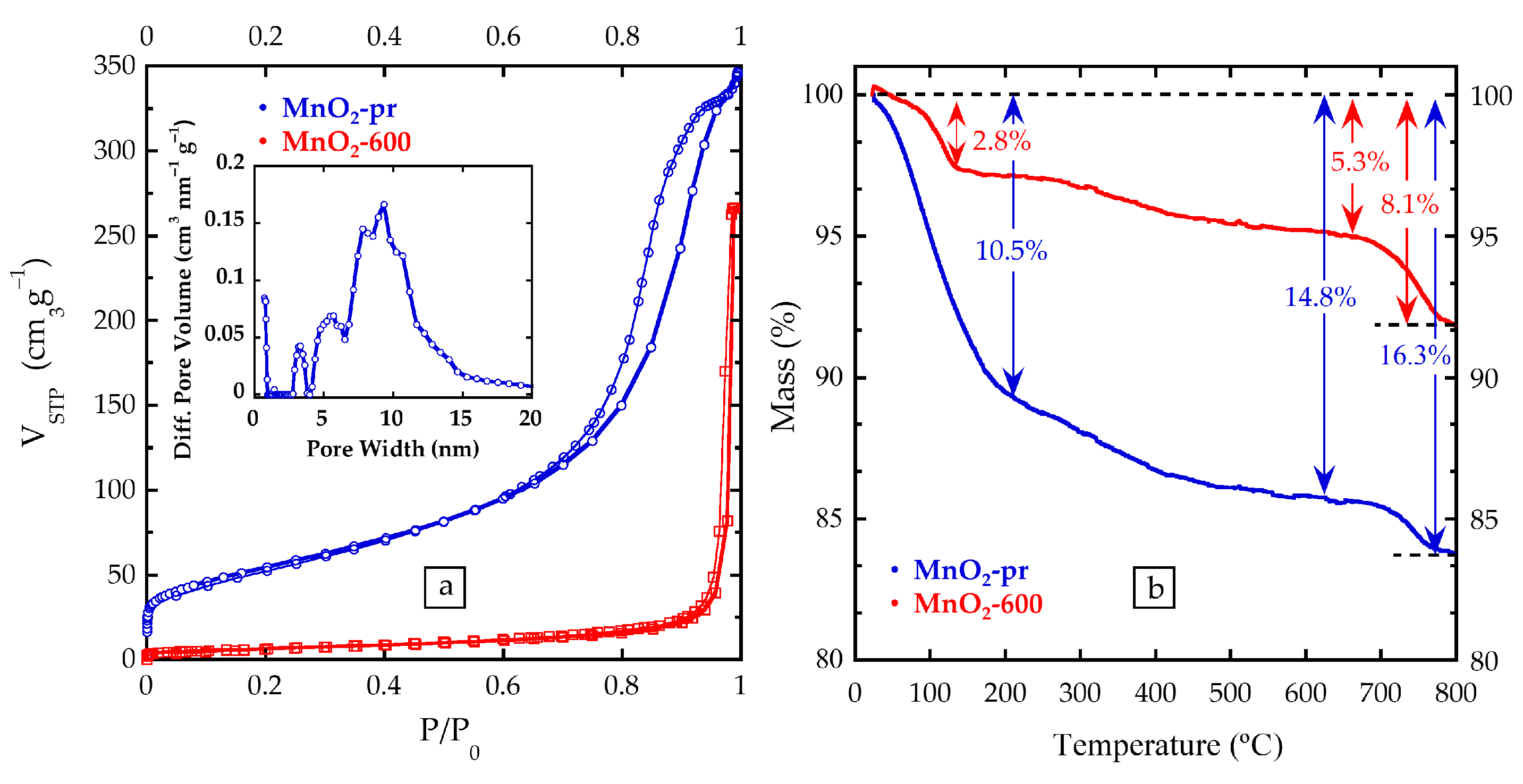
Due to the smaller particle size of the MnO2-pr sample, a much larger SSA could be expected, which would translate into a higher capacitance value, since the redox reactions responsible for the capacitive response take place on the surface. According to IUPAC, the nitrogen adsorption/desorption isotherm of sample MnO2-pr shown in Figure 4a corresponds to a type IV. It can be related to the formation of a monolayer in the low-pressure zone, followed by a weak bonded multilayer, and the hysteresis curve around 0.7 P/P° could indicate the existence of a mesoporous structure. On the other hand, the isotherm of MnO2-600 is of type III, which is often related to the formation of random multilayers from the beginning [57]. The calculated BET SSA values are 197 m2 g−1 for MnO2-pr and 24 m2 g−1 for MnO2-600, which uphold the deduction of MnO2-pr having smaller particle size and larger SSA than the treated sample. As can be observed in the inset of Figure 4a, the non-local density functional theory (NLDFT) treatment was applied to the isotherm registered by the most porous sample, MnO2-pr, in order to obtain a pores size distribution of the sample. The curve indicates a microporosity with pores, formed by the space between particles, of around 1 nm but also a mesoporosity of wider pores between 5 and 15 nm, averaging at 10 nm.
3.3. Compositional Characterization of MnO2: Thermogravimetric Analysis and Inductively Coupled Plasma-Atomic Emission Spectroscopy
Figure 4b shows the TGA curves for both MnO2-pr and MnO2-600 samples performed under Ar atmosphere and up to 800 °C. The mass losses between 100 and 200 °C would correspond to the H2O molecules adsorbed on the surface of the materials, 10.5% for sample MnO2-pr and 2.8% for MnO2-600. Subsequently, between 200 and 600 °C, a mass loss of 2–4% has been measured in MnO2-pr. This fact may be due to the loss of water molecules stored between layers in the layered structure of the thermally untreated sample. During the heat treatment, a reorganization of the oxide structure takes place due to the destabilization of the layered structure, moving from δ-MnO2 to α-MnO2 [58,59]. On the other hand, in the MnO2-600 sample, since these internal water molecules have already been lost in the heat treatment, the 2.5% mass loss in that temperature range may be due to the release of adsorbed CO2 molecules [60]. Finally, between 600 and 800 °C, a third mass loss occurs, probably corresponding to the release of oxygen due to the partial reduction of Mn(IV) [59].
Since the synthesis of the MnO2 samples is based on the reduction of potassium permanganate, IPC-AES measurements were performed to determine the amount of potassium in the samples. The calculated atomic ratios of K:Mn are 0.27:1(MnO2-pr) and 0.26:1 (MnO2-600). Therefore, potassium is present in both samples despite the thermal treatment. These data, together with TGA results, made it possible to obtain the exact formulas of the two samples: K0.27MnO2·0.27H2O in the untreated sample, and K0.26MnO2, when treated at 600 °C. As Qu et al., explained, MnO2 samples with this K:Mn ratio contain K+ ions and water molecules as pillars to help with stabilizing the crystalline structure between the sheets. Furthermore, the authors obtained similar XRD diffraction patterns before and after 10,000 charge/discharge cycles, concluding that there are almost no changes in the crystalline structure during the long-term cycling [61].
3.4. Electrochemical Characterization of MnO2 Electrodes
Before building the hybrid systems, the electrochemical study of each material was performed. Figure 5 shows the CV curves of the MnO2-pr and MnO2-600 samples along with the measurements of the commercial AC. The CV curves of the AC exhibit a rectangular-like shape in all three electrolytes, i.e., Na2SO4, KOH and Na2SO4 + MnSO4, typical of capacitive behaviour. Oxide samples, however, show more irregular profiles due to the Faradaic charge transfer reactions [62].
Furthermore, the manganese dioxide samples display potential windows at more positive values than the AC electrodes, confirming that they are more suitable as positive electrodes. The MnO2-pr sample reaches much higher capacitance values than the thermal treated sample in all three electrolytes, although the MnO2-600 sample is stable in a wider potential window (+0.2 V). Figure 6 compiles the capacitance values obtained at the different sweep rates for all three samples in all three electrolytes.
In all three cases, capacitance values in the Na2SO4 + MnSO4 electrolyte are slightly higher than in Na2SO4; thus, the presence of Mn2+ species may have a positive effect on the electrochemical response [52]. Therefore, it has been thought to exclude the Na2SO4 electrolyte for the final system. The results obtained in the KOH electrolyte show greater differences. The working potential windows are shifted towards more negative potential values, and narrower windows than in sulphated electrolytes (0.8 V vs. 1.2 V) are observed, as can be observed in Figure 5. This behaviour fits with the general tendency of neutral electrolytes to present wider potential windows than alkaline ones [63]. The narrower potential window is a disadvantage, since the potential range contributes positively to the energy stored by the system. However, the MnO2-pr sample exhibits a higher capacitance value in the KOH electrolyte compared to the values obtained in the sulphated electrolytes (237 F g−1 vs. 180 F g−1). Thus, to conclude which electrolyte will have a more positive impact on the electrochemical response of the final system, a MnO2-pr//AC final system is set up in both Na2SO4 + MnSO4 and KOH electrolytes.
To optimize the system and to balance the negative and positive charges through the appropriate mass balance, it is necessary to know the capacity of the individual electrodes, as the capacity per mass unit represents the accumulated or released charge in the electrode. Figure 6 also shows this parameter with respect to the discharge time. In the Na2SO4 + MnSO4 electrolyte, the MnO2-pr electrode, except at very short discharge times, generally presents twice the capacity of the AC; therefore, the best mass balance for the final system would be 1:2, MnO2-pr:AC. In the KOH electrolyte, on the other hand, the two electrodes show equal capacitance values over the entire discharge times studied, so a 1:1 mass balance is used in that case.
3.5. Electrochemical Characterization of the Final Systems
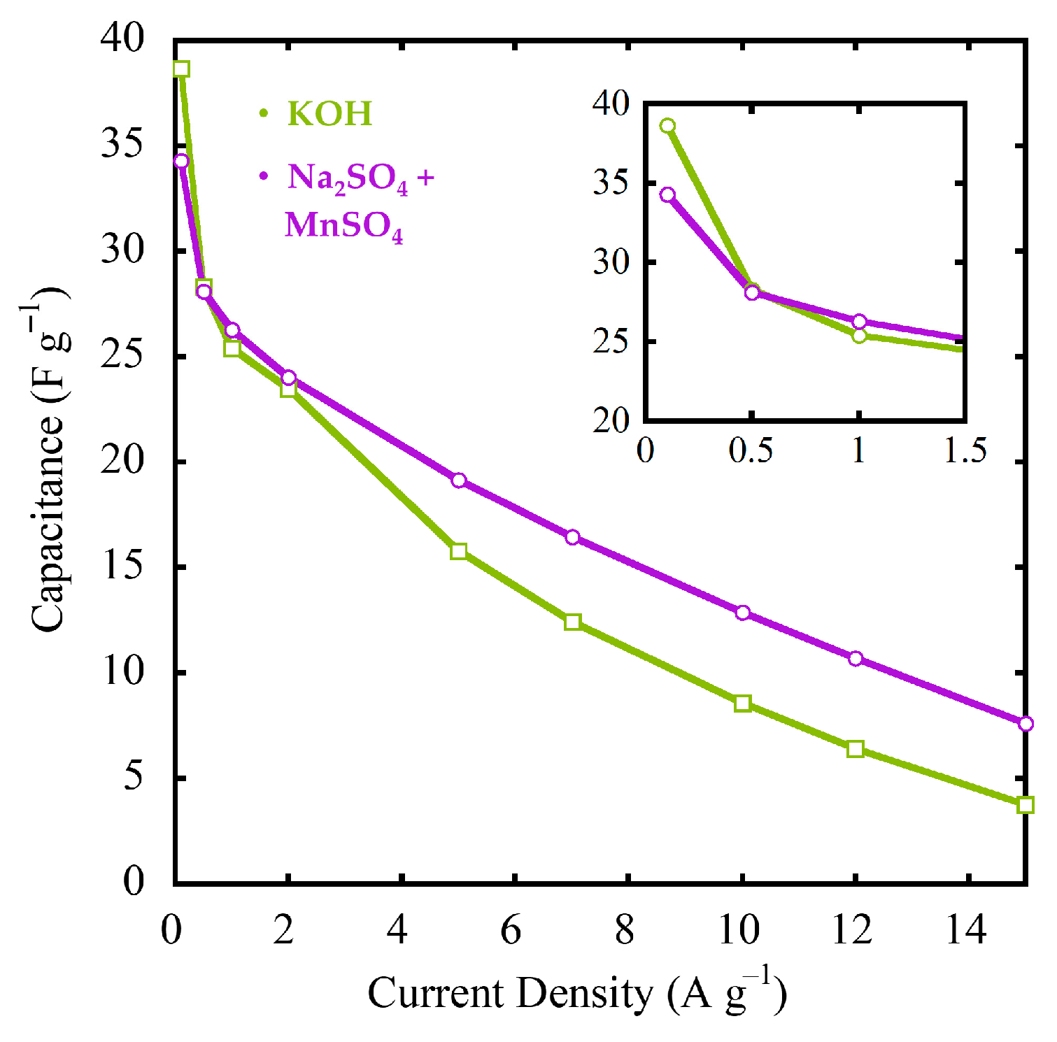
The working potential window of the final system in each of the electrolytes was estimated by voltammetry. As Figure 7 reports, both in alkali and neutral electrolytes the MnO2-pr//AC system exhibits CVs with a square profile in all of the explored sweep rates. The GAs were performed to calculate specific capacitances in the selected potential ranges and the charge/discharge profiles are linear at all current densities used (see Figure 7). The cells working in the Na2SO4 + MnSO4 electrolyte are able to operate at a 2 V cell voltage while those using KOH work at a cell voltage of 1.5 V. Specific capacitances were calculated from the GA cycles and are displayed in Figure 7. Excepting at current densities below 0.5 A g−1, the sulphated electrolyte obtains higher capacitances than KOH.
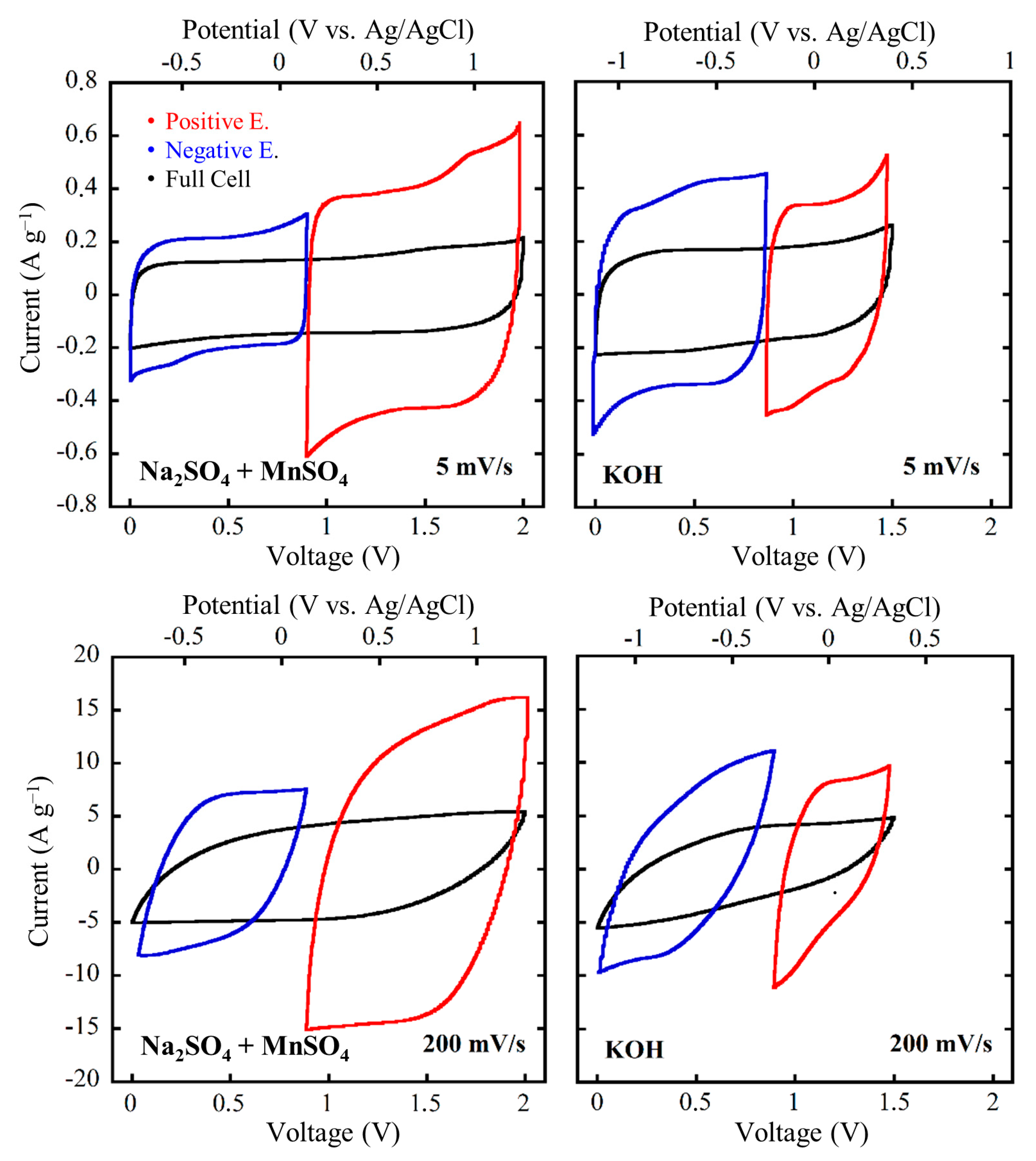
To examine in depth the behaviour of each electrode in the system, the CV curve of each electrode is presented in Figure 8. In the Na2SO4 + MnSO4 electrolyte, the operating potential range of the negative electrode is −0.7–0.2 V vs. Ag/AgCl and the positive is 0.2–1.4 V vs. Ag/AgCl, which are slightly lower than those in Figure 5. This suggests that these potential windows could be expanded by slightly changing the mass balance. Furthermore, it can be observed that the positive electrode achieves higher specific capacitance values due to the different mass loadings on the electrodes. In the KOH electrolyte, the negative AC electrode works between −1.1 and −0.25 V vs. Ag/AgCl and the positive between −0.25 and 0.4 V vs. Ag/AgCl, obtaining similar current values. Once again, both potential windows have been slightly lower than those measured in the 3-electrode cells (Figure 5); therefore, it might be possible to extend the cell voltage to enhance the energy storage.
As can be seen in Figure 9, the system built with the Na2SO4 + MnSO4 electrolyte has shown higher capacitances in all of the current densities above 0.5 A g−1, and it has been stable in wider operating voltage values, as shown in Figure 8. These results lead to expected higher energy density values in that system. In Figure 10a, a “Ragone plot” has been charted, which compares energy density against power density.
Na2SO4 + MnSO4 has reported higher energy densities for all of the measured specific powers, so it can be concluded that it is a most suitable electrolyte for this system. Furthermore, the neutral nature of Na2SO4 + MnSO4 plays in favour of the sustainability and the useful life of the cell, since non-neutral aqueous electrolytes usually present technical drawbacks, mainly due their corrosive character [63]. To find out how the system behaves over time, it was cycled with 1 A g−1 for 5000 GA charge/discharge cycles, as shown in Figure 10b. During the cyclability study, both electrodes remain stable, far exceeding 80% capacitance retention. In the first cycles (<1000 charge/discharge cycles), known as the pre-adaptation cycles, both show an increase in capacitance of approximately 15% because the system did not undergo the pre-conditioning cycles, as might be expected from commercial cells. Still, given the high retention obtained in these measurements, i.e., almost no change after 5000 cycles, both systems could be considered as potential candidates for high-cyclability aqueous hybrid electrochemical capacitors [64]. The latest literature reporting MnO2-based asymmetric systems rely on complex composite materials, ultrathin layers and N-doped carbonaceous materials [64,65,66,67,68]. The present work manages to achieve similar results, in the same order of magnitude and in a simpler and more scalable way, which supports the fact that the simpler manufacturing process of aqueous pseudocapacitive asymmetric systems is an additional asset of these energy storage devices.
The use of MnO2 as a pseudocapacitive material continues to be the focus of attention in research. The advances in the green synthesis and in the electrochemical performance of this material are pushing it towards an increasingly near-possible commercialization. The road ahead possibly awaits many challenges, but it is worthwhile to take advantage of the excellent properties of this material in a progressively cheaper, sustainable and simpler way. In addition, the advances made in this aspect could not only be used in energy storage systems but also in other areas of knowledge.
4. Conclusions
In summary, in this study, laboratory-grade hybrid supercapacitor cells have been successfully constructed using δ-MnO2 as the positive electrodes and a commercial activated carbon as the negative electrode. The nanostructured δ-MnO2 with the formula K0.27MnO2·0.27 H2O was prepared by reducing KMnO4 with ethylene glycol. Later, a 600 °C heat treatment was applied to the sample, changing the crystalline structure and particle size of the initial compound from the δ-MnO2 layered phase to a α-MnO2 2 × 2 tunnel phase with the K0.26MnO2 formula. These samples present the highest capacitance values in the 1 M KOH electrolyte, but they can work in a wider potential window in the 0.5 M Na2SO4 + 0.2 mM MnSO4 electrolyte; thus, two final systems have been built, one with each electrolyte. Due to the wider voltage obtained in the sulphated electrolyte (2.0 V vs. 1.5 V) and the higher capacitance values obtained in general, it has been concluded that the 0.5 M Na2SO4 + 0.2 mM MnSO4 electrolyte is more suitable for this δ-MnO2//AC combination. The system has shown an energy density of 15.6 Wh kg−1 at a power of 1.0 kW kg−1 and no capacitance loss after 5000 charge/discharge cycles.
Author Contributions
Conceptualization: I.R.d.L. and E.G.; methodology, validation, formal analysis, investigation, resources, data curation: J.R.-R., I.R.d.L. and E.G.; writing—original draft preparation: J.R.-R.; writing—review and editing: J.R.-R., I.R.d.L. and E.G.; supervision, project administration, funding acquisition: I.R.d.L. and E.G. All authors have read and agreed to the published version of the manuscript.
Funding
This research was funded by the Ministerio de Ciencia, Innovación y Universidades (PID2019-107468RB-C21 and TED2021-131517B-C21) and Gobierno Vasco/Eusko Jaurlaritza (IT1546-22).
Data Availability Statement
The data presented in this study are available on request from the corresponding authors.
Acknowledgments
The authors want to acknowledge Garikoitz Beobide for the nitrogen adsorption/desorption measurements. Finally, the authors are thankful for the technical and physical support provided by SGIker of UPV/EHU and European funding (ERDF and ESF).
Conflicts of Interest
The authors declare no conflict of interest.
References
- Kondrat, S.; Georgi, N.; Fedorov, M.V.; Kornyshev, A.A. A Superionic State in Nano-Porous Double-Layer Capacitors: Insights from Monte Carlo Simulations. Proc. Phys. Chem. Chem. Phys. 2011, 13, 11359–11366. [Google Scholar] [CrossRef] [PubMed]
- Shanti, S.; Ravi, S. Electrochemical Study of Al Doped MnO2 Nanorods Over Stainless Steel Substrate. Int. J. Chemtech. Res. 2014, 6, 2066–2068. [Google Scholar]
- Cui, Z.; Kang, L.; Li, L.; Wang, L.; Wang, K. A Hybrid Neural Network Model with Improved Input for State of Charge Estimation of Lithium-Ion Battery at Low Temperatures. Renew. Energy 2022, 198, 1328–1340. [Google Scholar] [CrossRef]
- Li, D.; Yang, D.; Li, L.; Wang, L.; Wang, K. Electrochemical Impedance Spectroscopy Based on the State of Health Estimation for Lithium-Ion Batteries. Energies 2022, 15, 6665. [Google Scholar] [CrossRef]
- Guo, Y.; Zhu, Z.; Chen, Y.; He, H.; Li, X.; Qin, T.; Wang, Y. High-Performance Supercapacitors of Ruthenium-Based Nanohybrid Compounds. J. Alloys Compd. 2020, 842, 155798. [Google Scholar] [CrossRef]
- Goda, E.S.; Lee, S.; Sohail, M.; Yoon, K.R. Prussian Blue and Its Analogues as Advanced Supercapacitor Electrodes. J. Energy Chem. 2020, 50, 206–229. [Google Scholar] [CrossRef]
- Dubal, D.P.; Wu, Y.P.; Holze, R. Supercapacitors: From the Leyden Jar to Electric Busses. ChemTexts 2016, 2, 1–19. [Google Scholar] [CrossRef] [Green Version]
- Mamun, A.-A.; Liu, Z.; Rizzo, D.M.; Onori, S. An Integrated Design and Control Optimization Framework for Hybrid Military Vehicle Using Lithium-Ion Battery and Supercapacitor as Energy Storage Devices. IEEE Trans. Transp. Electrif. 2019, 5, 239–251. [Google Scholar] [CrossRef]
- Zhan, Y.; Guo, Y.; Zhu, J.; Li, L. Power and Energy Management of Grid/PEMFC/Battery/Supercapacitor Hybrid Power Sources for UPS Applications. Int. J. Electr. Power Energy Syst. 2015, 67, 598–612. [Google Scholar] [CrossRef] [Green Version]
- Smolinka, T.; Ojong, E.T. Electrochemical Energy Storage for Renewable Sources and Grid Balancing. In Electrochemical Energy Storage for Renewable Sources and Grid Balancing; Elsevier: Amsterdam, The Netherlands, 2015; pp. 103–128. [Google Scholar]
- Pan, H.; Li, J.; Feng, Y.P. Carbon Nanotubes for Supercapacitor. Nanoscale Res. Lett. 2010, 5, 654–668. [Google Scholar] [CrossRef] [Green Version]
- Wen, L.; Li, F.; Cheng, H.M. Carbon Nanotubes and Graphene for Flexible Electrochemical Energy Storage: From Materials to Devices. Adv. Mater. 2016, 28, 4306–4337. [Google Scholar] [CrossRef] [PubMed]
- Yang, W.; Ni, M.; Ren, X.; Tian, Y.; Li, N.; Su, Y.; Zhang, X. Graphene in Supercapacitor Applications. Curr. Opin. Colloid Interface Sci. 2015, 20, 416–428. [Google Scholar] [CrossRef]
- Ghosh, A.; Lee, Y.H. Carbon-Based Electrochemical Capacitors. ChemSusChem 2012, 5, 480–499. [Google Scholar] [CrossRef] [PubMed]
- dos Reis, G.S.; de Oliveira, H.P.; Larsson, S.H.; Thyrel, M.; Lima, E.C. A Short Review on the Electrochemical Performance of Hierarchical and Nitrogen-Doped Activated Biocarbon-Based Electrodes for Supercapacitors. Nanomaterials 2021, 11, 1–17. [Google Scholar]
- dos Reis, G.S.; Larsson, S.H.; de Oliveira, H.P.; Thyrel, M.; Lima, E.C. Sustainable Biomass Activated Carbons as Electrodes for Battery and Supercapacitors—A Mini-Review. Nanomaterials 2020, 10, 1398. [Google Scholar] [CrossRef]
- Hu, W.; Xiang, R.; Lin, J.; Cheng, Y.; Lu, C. Lignocellulosic Biomass-Derived Carbon Electrodes for Flexible Supercapacitors: An Overview. Materials 2021, 14, 4571. [Google Scholar] [CrossRef]
- Choi, N.S.; Chen, Z.; Freunberger, S.A.; Ji, X.; Sun, Y.K.; Amine, K.; Yushin, G.; Nazar, L.F.; Cho, J.; Bruce, P.G. Challenges Facing Lithium Batteries and Electrical Double-Layer Capacitors. Angew. Chem. 2012, 51, 9994–10024. [Google Scholar] [CrossRef]
- Xiong, W.; Liu, M.; Gan, L.; Lv, Y.; Li, Y.; Yang, L.; Xu, Z.; Hao, Z.; Liu, H.; Chen, L. A Novel Synthesis of Mesoporous Carbon Microspheres for Supercapacitor Electrodes. J. Power Sources 2011, 196, 10461–10464. [Google Scholar] [CrossRef]
- Hu, Z.; Srinivasan, M.P. Preparation of High-Surface-Area Activated Carbons from Coconut Shell; Elsevier: Amsterdam, The Netherlands, 1999; Volume 27. [Google Scholar]
- Lu, X.; Shen, C.; Zhang, Z.; Barrios, E.; Zhai, L. Core-Shell Composite Fibers for High-Performance Flexible Supercapacitor Electrodes. ACS Appl. Mater. Interfaces 2018, 10, 4041–4049. [Google Scholar] [CrossRef]
- Cao, Y.; Li, S.; Xu, C.; Ma, X.; Huang, G.; Lu, C.; Li, Z. Mechanisms of Porous Carbon-Based Supercapacitors. ChemNanoMat 2021, 7, 1273–1290. [Google Scholar] [CrossRef]
- Gummow, R.J.; de Kock, A.; Thackeray, M.M. Improved Capacity Retention in Rechargeable 4 V Lithium/Lithium-Manganese Oxide (Spinel) Cells. Solid State Ion. 1994, 69, 59–67. [Google Scholar] [CrossRef]
- Shin, J.; Seo, J.K.; Yaylian, R.; Huang, A.; Meng, Y.S. A Review on Mechanistic Understanding of MnO2 in Aqueous Electrolyte for Electrical Energy Storage Systems. Int. Mater. Rev. 2020, 65, 356–387. [Google Scholar] [CrossRef]
- Qi, H.; Bo, Z.; Yang, S.; Duan, L.; Yang, H.; Yan, J.; Cen, K.; Ostrikov, K. (Ken) Hierarchical Nanocarbon-MnO2 Electrodes for Enhanced Electrochemical Capacitor Performance. Energy Storage Mater. 2019, 16, 607–618. [Google Scholar] [CrossRef]
- Reddy, R.N.; Reddy, R.G. Sol-Gel MnO2 as an Electrode Material for Electrochemical Capacitors. J. Power Sources 2003, 124, 330–337. [Google Scholar] [CrossRef]
- Ohzuku, T.; Kitigawa, M.; Hirai, T. Electrochemistry of Manganese Dioxide in Lithium Nonaqueous Cell. J. Electrochem. Soc. 1990, 137, 769–775. [Google Scholar] [CrossRef]
- Shrestha, D.; Maensiri, S.; Wongpratat, U.; Lee, S.W.; Nyachhyon, A.R. Shorea Robusta Derived Activated Carbon Decorated with Manganese Dioxide Hybrid Composite for Improved Capacitive Behaviors. J. Environ. Chem. Eng. 2019, 7, 1137–1146. [Google Scholar] [CrossRef]
- Lee, J.Y.; Liang, K.; An, K.H.; Lee, Y.H. Nickel Oxide/Carbon Nanotubes Nanocomposite for Electrochemical Capacitance. Synth. Met. 2005, 150, 153–157. [Google Scholar] [CrossRef]
- Huang, Q.; Zhao, J.; Liu, M.; Li, Y.; Ruan, J.; Li, Q.; Tian, J.; Zhu, X.; Zhang, X.; Wei, Y. Synthesis of Polyacrylamide Immobilized Molybdenum Disulfide (MoS2@PDA@PAM) Composites via Mussel-Inspired Chemistry and Surface-Initiated Atom Transfer Radical Polymerization for Removal of Copper (II) Ions. J. Taiwan Inst. Chem. Eng. 2018, 86, 174–184. [Google Scholar] [CrossRef]
- Rakhi, R.B.; Chen, W.; Hedhili, M.N.; Cha, D.; Alshareef, H.N. Enhanced Rate Performance of Mesoporous Co3O4 Nanosheet Supercapacitor Electrodes by Hydrous RuO2 Nanoparticle Decoration. ACS Appl. Mater. Interfaces 2014, 6, 4196–4206. [Google Scholar] [CrossRef]
- Cheng, Q.; Tang, J.; Ma, J.; Zhang, H.; Shinya, N.; Qin, L.C. Graphene and Carbon Nanotube Composite Electrodes for Supercapacitors with Ultra-High Energy Density. Phys. Chem. Chem. Phys. 2011, 13, 17615–17624. [Google Scholar] [CrossRef]
- Qu, Q.; Zhang, P.; Wang, B.; Chen, Y.; Tian, S.; Wu, Y.; Holze, R. Electrochemical Performance of MnO2 Nanorods in Neutral Aqueous Electrolytes as a Cathode for Asymmetric Supercapacitors. J. Phys. Chem. C 2009, 113, 14020–14027. [Google Scholar] [CrossRef]
- Augustyn, V.; Simon, P.; Dunn, B. Pseudocapacitive Oxide Materials for High-Rate Electrochemical Energy Storage. Energy Environ. Sci. 2014, 7, 1597–1614. [Google Scholar] [CrossRef]
- Toupin, M.; Brousse, T.; Bélanger, D. Charge Storage Mechanism of MnO2 Electrode Used in Aqueous Electrochemical Capacitor. Chem. Mater. 2004, 16, 3184–3190. [Google Scholar] [CrossRef]
- Jayachandran, M.; Rose, A.; Maiyalagan, T.; Poongodi, N.; Vijayakumar, T. Effect of Various Aqueous Electrolytes on the Electrochemical Performance of α-MnO2 Nanorods as Electrode Materials for Supercapacitor Application. Electrochim. Acta 2020, 366, 137412. [Google Scholar] [CrossRef]
- Xu, C.; Kang, F.; Li, B.; Du, H. Recent Progress on Manganese Dioxide Based Supercapacitors. J. Mater. Res. 2010, 25, 1421–1432. [Google Scholar] [CrossRef]
- Wei, W.; Cui, X.; Chen, W.; Ivey, D.G. Manganese Oxide-Based Materials as Electrochemical Supercapacitor Electrodes. Chem. Soc. Rev. 2011, 40, 1697–1721. [Google Scholar] [CrossRef]
- Han, G.; Liu, Y.; Zhang, L.; Kan, E.; Zhang, S.; Tang, J.; Tang, W. MnO2 Nanorods Intercalating Graphene Oxide/Polyaniline Ternary Composites for Robust High-Performance Supercapacitors. Sci. Rep. 2014, 4, 4824. [Google Scholar] [CrossRef] [Green Version]
- Chang, J.; Jin, M.; Yao, F.; Kim, T.H.; Le, V.T.; Yue, H.; Gunes, F.; Li, B.; Ghosh, A.; Xie, S.; et al. Asymmetric Supercapacitors Based on Graphene/MnO2 Nanospheres and Graphene/MoO3 Nanosheets with High Energy Density. Adv. Funct. Mater. 2013, 23, 5074–5083. [Google Scholar] [CrossRef]
- Babakhani, B.; Ivey, D.G. Improved Capacitive Behavior of Electrochemically Synthesized Mn Oxide/PEDOT Electrodes Utilized as Electrochemical Capacitors. Electrochim. Acta 2010, 55, 4014–4024. [Google Scholar] [CrossRef]
- Reddy, A.L.M.; Shaijumon, M.M.; Gowda, S.R.; Ajayan, P.M. Multisegmented Au-MnO2/Carbon Nanotube Hybrid Coaxial Arrays for High-Power Supercapacitor Applications. J. Phys. Chem. C 2010, 114, 658–663. [Google Scholar] [CrossRef]
- Xu, M.; Kong, L.; Zhou, W.; Li, H. Hydrothermal Synthesis and Pseudocapacitance Properties of α-MnO2 Hollow Spheres and Hollow Urchins. J. Phys. Chem. C 2007, 111, 19141–19147. [Google Scholar] [CrossRef]
- Wu, D.; Xie, X.; Zhang, Y.; Zhang, D.; Du, W.; Zhang, X.; Wang, B. MnO2/Carbon Composites for Supercapacitor: Synthesis and Electrochemical Performance. Front. Mater. 2020, 7, 2. [Google Scholar] [CrossRef]
- Lee, H.Y.; Goodenough, J.B. Brief communication: Supercapacitor Behavior with KCl Electrolyte. J. Solid. State Chem. 1999, 144, 220–223. [Google Scholar] [CrossRef]
- Brousse, T.; Toupin, M.; Dugas, R.; Athouël, L.; Crosnier, O.; Bélanger, D. Crystalline MnO[Sub 2] as Possible Alternatives to Amorphous Compounds in Electrochemical Supercapacitors. J. Electrochem. Soc. 2006, 153, A2171. [Google Scholar] [CrossRef]
- Lu, X.; Zheng, D.; Zhai, T.; Liu, Z.; Huang, Y.; Xie, S.; Tong, Y. Facile Synthesis of Large-Area Manganese Oxide Nanorod Arrays as a High-Performance Electrochemical Supercapacitor. Energy Environ. Sci. 2011, 4, 2915–2921. [Google Scholar] [CrossRef]
- Wang, J.-W.; Chen, Y.; Chen, B.-Z. A Synthesis Method of MnO2/Activated Carbon Composite for Electrochemical Supercapacitors. J. Electrochem. Soc. 2015, 162, A1654–A1661. [Google Scholar] [CrossRef]
- Lee, H.Y.; Kim, S.W.; Lee, H.Y. Expansion of Active Site Area and Improvement of Kinetic Reversibility in Electrochemical Pseudocapacitor Electrode. Electrochem. Solid-State Lett. 2001, 4, A19–A22. [Google Scholar] [CrossRef]
- Chen, P.C.; Shen, G.; Shi, Y.; Chen, H.; Zhou, C. Preparation and Characterization of Flexible Asymmetric Supercapacitors Based on Transition-Metal-Oxide Nanowire/Single-Walled Carbon Nanotube Hybrid Thin-Film Electrodes. ACS Nano 2010, 4, 4403–4411. [Google Scholar] [CrossRef]
- Ragupathy, P.; Park, D.H.; Campet, G.; Vasan, H.N.; Hwang, S.J.; Choy, J.H.; Munichandraiah, N. Remarkable Capacity Retention of Nanostructured Manganese Oxide upon Cycling as an Electrode Material for Supercapacitor. J. Phys. Chem. C 2009, 113, 6303–6309. [Google Scholar] [CrossRef]
- Liu, C.; Chen, Y.; Dong, Z.; Wu, X.; Situ, Y.; Huang, H. Tuning Mn 2+ Additive in the Aqueous Electrolyte for Enhanced Cycling Stability of Birnessite Electrodes. Electrochim. Acta 2019, 298, 678–684. [Google Scholar] [CrossRef]
- Julien, C.; Massot, M.; Baddour-Hadjean, R.; Franger, S.; Bach, S.; Pereira-Ramos, J.P. Raman Spectra of Birnessite Manganese Dioxides. Solid State Ion. 2003, 159, 345–356. [Google Scholar] [CrossRef]
- Julien, C.M.; Massot, M.; Poinsignon, C. Lattice Vibrations of Manganese Oxides: Part I. Periodic Structures. Spectrochim. Acta A Mol. Biomol. Spectrosc. 2004, 60, 689–700. [Google Scholar] [CrossRef]
- Gao, T.; Fjellvåg, H.; Norby, P. A Comparison Study on Raman Scattering Properties of α- and β-MnO2. Anal. Chim. Acta 2009, 648, 235–239. [Google Scholar] [CrossRef] [PubMed]
- Buciuman, F.; Patcas, F.; Craciun, R.; Zahn, D.R.T. Vibrational Spectroscopy of Bulk and Supported Manganese Oxides. Phys. Chem. Chem. Phys. 1998, 1, 185–190. [Google Scholar] [CrossRef]
- Sing, K.S.W.; Everett, D.H.; Haul, R.A.W.; Moscou, L.; Pierotti, R.A.; Rouquérol, J.; Siemieniewska, T. Reporting Physisorption Data for Gas/Solid Systems with Special Reference to the Determination of Surface Area and Porosity. Pure Appl. Chem. 1985, 57, 603–619. [Google Scholar] [CrossRef]
- Ghodbane, O.; Pascal, J.L.; Fraisse, B.; Favier, F. Structural in Situ Study of the Thermal Behavior of Manganese Dioxide Materials: Toward Selected Electrode Materials for Supercapacitors. ACS Appl. Mater. Interfaces 2010, 2, 3493–3505. [Google Scholar] [CrossRef]
- Yang, X.; Makita, Y.; Liu, Z.H.; Sakane, K.; Ooi, K. Structural Characterization of Self-Assembled MnO2 Nanosheets from Birnessite Manganese Oxide Single Crystals. Chem. Mater. 2004, 16, 5581–5588. [Google Scholar] [CrossRef]
- Valente, J.S.; Frías, D.; Navarro, P.; Montes, M.; Delgado, J.J.; Fregoso-Israel, E.; Torres-García, E. Manganese Cryptomelane-Type Oxides: A Thermo-Kinetic and Morphological Study. Appl. Surf. Sci. 2008, 254, 3006–3013. [Google Scholar] [CrossRef]
- Qu, Q.; Li, L.; Tian, S.; Guo, W.; Wu, Y.; Holze, R. A Cheap Asymmetric Supercapacitor with High Energy at High Power: Activated Carbon//K0.27MnO2·0.6H2O. J. Power Sources 2010, 195, 2789–2794. [Google Scholar] [CrossRef]
- Goikolea, E.; Mysyk, R. Nanotechnology in Electrochemical Capacitors. In Emerging Nanotechnologies in Rechargable Energy Storage Systems; Elsevier: Amsterdam, The Netherlands, 2017; pp. 131–169. [Google Scholar]
- Bichat, M.P.; Raymundo-Piñero, E.; Béguin, F. High Voltage Supercapacitor Built with Seaweed Carbons in Neutral Aqueous Electrolyte. Carbon 2010, 48, 4351–4361. [Google Scholar] [CrossRef]
- Sharma, R.K.; Oh, H.S.; Shul, Y.G.; Kim, H. Carbon-Supported, Nano-Structured, Manganese Oxide Composite Electrode for Electrochemical Supercapacitor. J. Power Sources 2007, 173, 1024–1028. [Google Scholar] [CrossRef]
- Li, S.; Gao, L.; Wang, L.; Wang, M.; Shen, Y. Hierarchical MnO2 Located on Carbon Nanotubes for Enhanced Electrochemical Performance. ChemElectroChem 2018, 5, 1525–1531. [Google Scholar] [CrossRef]
- Wen, J.; Chen, X.; Huang, M.; Yang, W.; Deng, J. Core-Shell-Structured MnO2 @carbon Spheres and Nitrogen-Doped Activated Carbon for Asymmetric Supercapacitors with Enhanced Energy Density. J. Chem. Sci. 2020, 132, 1–11. [Google Scholar] [CrossRef]
- Li, X.; Wang, Z.; Guo, L.; Han, D.; Li, B.; Gong, Z. Manganese Oxide/Hierarchical Porous Carbon Nanocomposite from Oily Sludge for High-Performance Asymmetric Supercapacitors. Electrochim. Acta 2018, 265, 71–77. [Google Scholar] [CrossRef]
- Li, M.; Chen, Q.; Zhan, H. Ultrathin Manganese Dioxide Nanosheets Grown on Partially Unzipped Nitrogen-Doped Carbon Nanotubes for High-Performance Asymmetric Supercapacitors. J. Alloys Compd. 2017, 702, 236–243. [Google Scholar] [CrossRef]
Figure 1.
(a) XRD patterns of the MnO2 sample after every heat treatment. Profile fittings of the XRD patterns of (b) MnO2 as synthesized (pristine) and (c) the MnO2 sample treated at 600 °C.
Figure 1.
(a) XRD patterns of the MnO2 sample after every heat treatment. Profile fittings of the XRD patterns of (b) MnO2 as synthesized (pristine) and (c) the MnO2 sample treated at 600 °C.

Figure 2.
Raman spectra of both manganese dioxide samples obtained by the synthesis and further heat treatment.
Figure 2.
Raman spectra of both manganese dioxide samples obtained by the synthesis and further heat treatment.
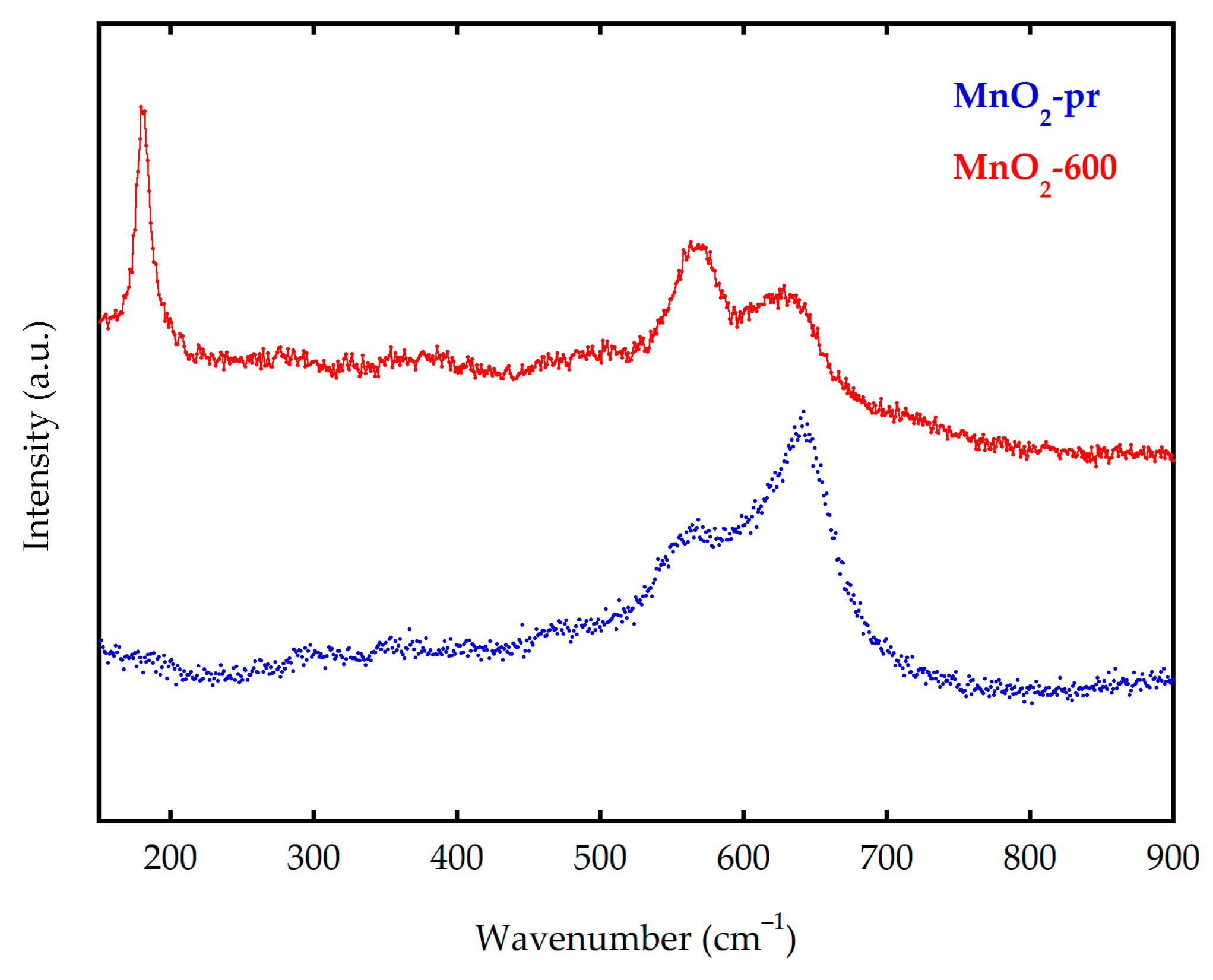
Figure 3.
SEM micrographs of (a,b) MnO2-pr and (e,f) MnO2-600. Manganese (blue) and oxygen (yellow) EDX mapping analysis for (c,d) MnO2-pr and (g,h) MnO2-600.
Figure 3.
SEM micrographs of (a,b) MnO2-pr and (e,f) MnO2-600. Manganese (blue) and oxygen (yellow) EDX mapping analysis for (c,d) MnO2-pr and (g,h) MnO2-600.
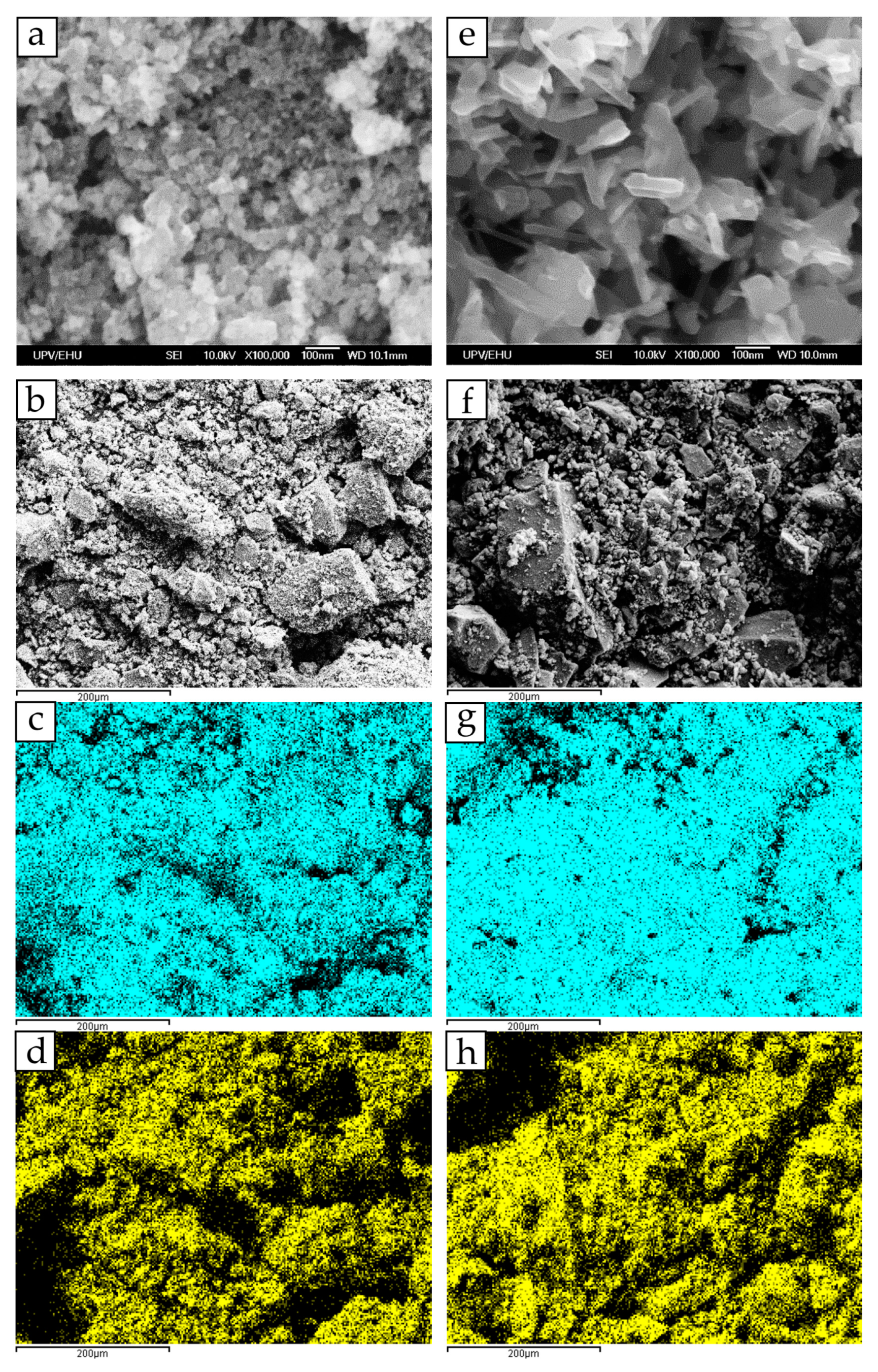
Figure 4.
(a) N2 adsorption isotherms for MnO2-pr and MnO2-600 manganese dioxide samples. Inset: Pore size distribution, calculated with the DFT method for the MnO2-pr sample. (b) TGA results for both samples.
Figure 4.
(a) N2 adsorption isotherms for MnO2-pr and MnO2-600 manganese dioxide samples. Inset: Pore size distribution, calculated with the DFT method for the MnO2-pr sample. (b) TGA results for both samples.

Figure 5.
Cyclic voltammograms of manganese dioxide samples and AC electrodes in 0.5 M Na2SO4 (Na2SO4), 1 M KOH (KOH) and 0.5 M Na2SO4 + 0.2 mM MnSO4 (Na2SO4 + MnSO4) electrolytes.
Figure 5.
Cyclic voltammograms of manganese dioxide samples and AC electrodes in 0.5 M Na2SO4 (Na2SO4), 1 M KOH (KOH) and 0.5 M Na2SO4 + 0.2 mM MnSO4 (Na2SO4 + MnSO4) electrolytes.
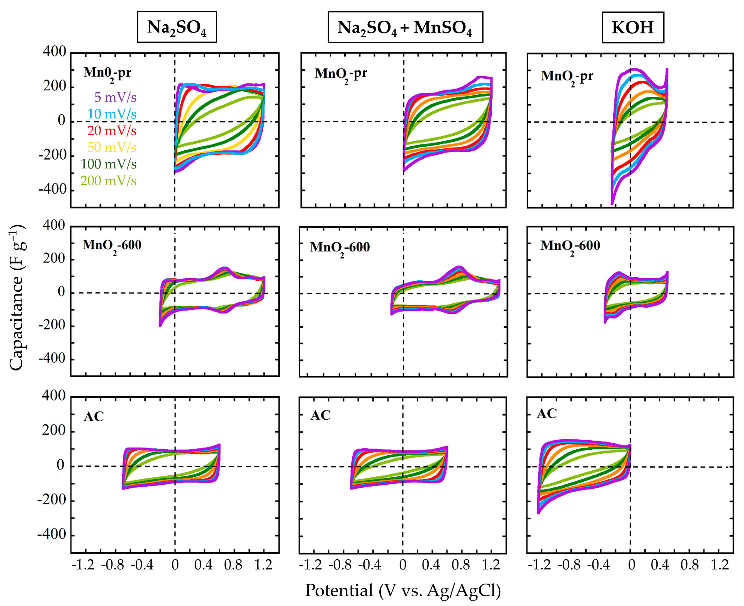
Figure 6.
Specific capacitances of MnO2-pr; MnO2-600 and AC samples at 0–200 mV s−1 scan rates (left) and vs. discharge time (right) in 0.5 M Na2SO4 (Na2SO4), 1 M KOH (KOH) and 0.5 M Na2SO4 + 0.2 mM MnSO4 (Na2SO4 + MnSO4) electrolytes. The insets show capacity values vs. discharge time.
Figure 6.
Specific capacitances of MnO2-pr; MnO2-600 and AC samples at 0–200 mV s−1 scan rates (left) and vs. discharge time (right) in 0.5 M Na2SO4 (Na2SO4), 1 M KOH (KOH) and 0.5 M Na2SO4 + 0.2 mM MnSO4 (Na2SO4 + MnSO4) electrolytes. The insets show capacity values vs. discharge time.
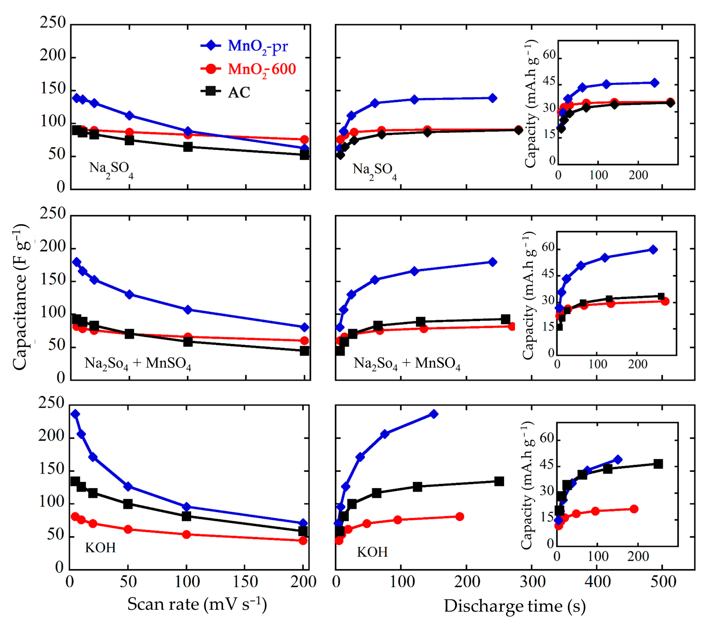
Figure 7.
CVs at 5, 10, 20, 50, 100 and 200 mV s−1—scan rates (left) and GA curves (right) of final systems in both electrolytes.
Figure 7.
CVs at 5, 10, 20, 50, 100 and 200 mV s−1—scan rates (left) and GA curves (right) of final systems in both electrolytes.
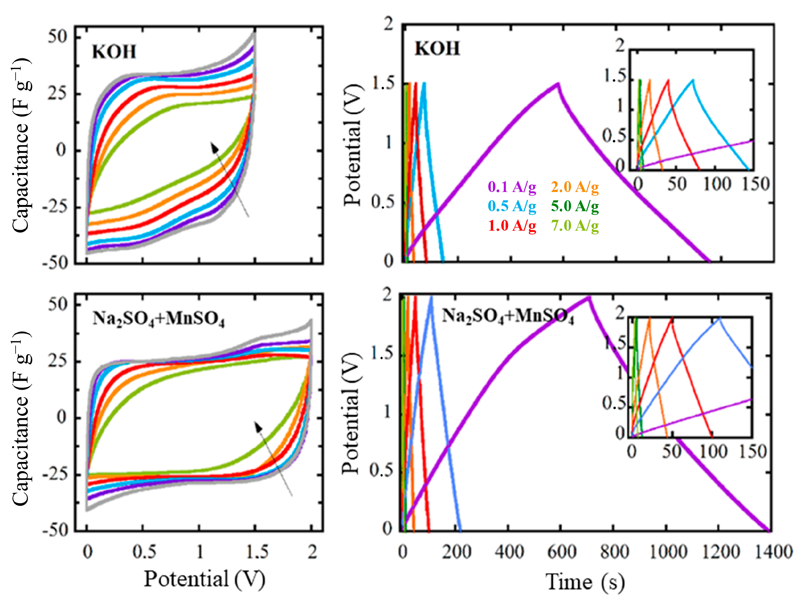
Figure 8.
Separate performance in CVs of the positive and negative electrodes, and full cells in both electrolytes at 5 and 200 mV s−1.
Figure 8.
Separate performance in CVs of the positive and negative electrodes, and full cells in both electrolytes at 5 and 200 mV s−1.

Figure 9.
Comparison of the capacitances of the final systems calculated from GA charge/discharge curves shown at Figure 7 for both electrolytes.
Figure 9.
Comparison of the capacitances of the final systems calculated from GA charge/discharge curves shown at Figure 7 for both electrolytes.

Figure 10.
(a) Ragone plot of the final systems in the two electrolytes and (b) capacitance values for 5000 charge/discharge cycles at 1 A g−1.
Figure 10.
(a) Ragone plot of the final systems in the two electrolytes and (b) capacitance values for 5000 charge/discharge cycles at 1 A g−1.

Publisher’s Note: MDPI stays neutral with regard to jurisdictional claims in published maps and institutional affiliations. |
© 2022 by the authors. Licensee MDPI, Basel, Switzerland. This article is an open access article distributed under the terms and conditions of the Creative Commons Attribution (CC BY) license (https://creativecommons.org/licenses/by/4.0/).
Share and Cite
MDPI and ACS Style
Rodriguez-Romero, J.; Ruiz de Larramendi, I.; Goikolea, E. Nanostructured Manganese Dioxide for Hybrid Supercapacitor Electrodes. Batteries 2022, 8, 263. https://doi.org/10.3390/batteries8120263
AMA Style
Rodriguez-Romero J, Ruiz de Larramendi I, Goikolea E. Nanostructured Manganese Dioxide for Hybrid Supercapacitor Electrodes. Batteries. 2022; 8(12):263. https://doi.org/10.3390/batteries8120263
Chicago/Turabian StyleRodriguez-Romero, Jon, Idoia Ruiz de Larramendi, and Eider Goikolea. 2022. "Nanostructured Manganese Dioxide for Hybrid Supercapacitor Electrodes" Batteries 8, no. 12: 263. https://doi.org/10.3390/batteries8120263
Note that from the first issue of 2016, this journal uses article numbers instead of page numbers. See further details here.