Article

Ionic Liquid-Laden Zn-MOF-74-Based Solid-State Electrolyte for Sodium Batteries

by
Alexander Mirandona-Olaeta
1,2,
Eider Goikolea
2,
Senentxu Lanceros-Mendez
1,3,
Arkaitz Fidalgo-Marijuan
1,2,* and
Idoia Ruiz de Larramendi
2,*
1
BCMaterials, Basque Center for Materials, Applications and Nanostructures, Bld. Martina Casiano, 3rd. Floor, UPV/EHU Science Park, 48940 Leioa, Spain
2
Department of Organic and Inorganic Chemistry, Universidad del País Vasco (UPV/EHU), Barrio Sarriena s/n, 48940 Leioa, Spain
3
IKERBASQUE, Basque Foundation for Science, 48009 Bilbao, Spain
*
Authors to whom correspondence should be addressed.
Batteries 2023, 9(12), 588; https://doi.org/10.3390/batteries9120588
Submission received: 6 November 2023 / Revised: 4 December 2023 / Accepted: 7 December 2023 / Published: 12 December 2023

Abstract

:
Sodium batteries are receiving increasing interest as an alternative to reduce dependence on lithium-based systems. Furthermore, the development of solid-state electrolytes will lead to higher-performing and safer devices. In this work, a Zn-based metal–organic framework (Zn-MOF-74) is combined as a physical barrier against the growth of dendrites, together with 1-ethyl-3-methylimidazolium bis(trifluoromethylsulfonyl)imide ([EMIm][TFSI]) ionic liquid, which provides improved mobility to sodium ions. It is demonstrated that the incorporation of the appropriate amount of ionic liquid within the pores of the MOF produces a considerable increase in ionic conductivity, achieving values as high as 5 × 10⁻⁴ S cm−1 at room temperature, in addition to an acceptable Na+ transference number. Furthermore, the developed Na[EMIm][TFSI]@Zn-MOF-74 hybrid solid electrolyte contributes to stable and dendrite-free sodium plating/stripping for more than 100 h. Finally, a more than notable extension of the electrochemical stability window of the electrolyte has been determined, being useful even above 7 V vs. Na+/Na. Overall, this work presents a suitable strategy for the next generation of solid-state sodium batteries.

Graphical Abstract

1. Introduction

Environmental concerns such as global warming and the scarcity of fossil resources have boosted the ongoing energy transition and awakened the search for less-polluting alternative energy sources [1]. Renewable energy sources have important benefits, such as being environmentally friendly, safe and unlimited. However, they depend upon the environment, the season, the weather and the day/night cycle, and thus, the peaks of maximum production do not necessarily coincide with those of highest demand, which requires the use of systems that store energy surplus [2]. Electrochemical energy storage (EES) devices are the most promising solution to solve the intermittency problem and support the implementation of renewable energies [3]. This need has driven the rapid development of EES technologies in recent decades, particularly lithium-ion batteries (LIBs), due to their high energy density, high charge retention capacity and wide range of operating temperatures [4]. In recognition of the vital role of these devices in our society, the late Professor John B. Goodenough and Professors M. Stanley Whittingham and Akira Yoshino were recognized with the 2019 Nobel Prize in Chemistry for the development of LIBs. Despite the clear interest in LIBs, there are some critical issues that must be considered for a future generation of batteries:
i.
Increase the energy density, which could be solved by developing batteries that use metallic lithium anodes. Lithium metal batteries are expected to be the next generation of energy storage devices since lithium anodes show a high theoretical capacity (3860 mA h g–1), the lowest redox potential (−3.04 V vs. the standard hydrogen electrode) and a low density (0.59 g cm–3). If safety and volume expansion issues associated with the use of metallic lithium are alleviated, it is certain that lithium metal batteries will provide a higher energy density than traditional graphite anode-based systems [5,6].
ii.
Properly address safety issues due to the use of liquid organic electrolytes. The use of liquid electrolytes based on the dissolution of a lithium salt (such as LiPF6) in a carbonated organic solvent carries significant risks. These organic liquid electrolytes are flammable and, with the heating of the battery during cycling, they can be related to the explosion or combustion of the device. This fact is aggravated when these toxic solvents leak, so the device must be tightly sealed. These solvent leaks contribute to a reduction in the useful life of the LIB [7].
iii.
Finally, lithium is considered a critical element due to its low abundance as well as problems related to accessibility, mining and sociopolitical conditions. Thus, lithium exploitation may not cover the future demand, and it is crucial to look for alternatives to LIBs, such as technologies based on other metallic elements like sodium. Both alkaline elements exhibit some chemical characteristics that, together with the high abundance of the heavier element, have driven the development of sodium-ion batteries (NIBs) as a promising alternative to LIBs [8,9].
A strategy that allows acting on the first two aforementioned issues focuses on the implementation of electrolytes in a (quasi)solid state since they exhibit excellent thermal and electrochemical stabilities. These electrolytes allow batteries to operate in a wider temperature range, from −50 to 200 °C and even higher. In addition, they allow for the reduction in the size of the device, an increase in the mechanical resistance of the battery and the energy and power densities and an improvement in the electrochemical stability [10]. One of the main advantages of using solid electrolytes focuses on the metal’s barrier effect on dendrite growth. The appearance of these dendrites is related to a loss of energy density and lower battery efficiency. Furthermore, dendrites can cause short-circuits and overheating of the device, causing serious safety problems [11].
In recent years, several families of porous materials have piqued the interest of researchers working in energy-related fields. Metal–organic frameworks (MOFs) are three-dimensional porous crystalline structures based on the union of different metal ions/aggregates through organic ligands. Benefiting from high surface area, controllable functionality and modularity, MOFs offer great prospects to manipulate the physicochemical properties and electrochemical response of solid-state electrolytes in high-energy-density batteries, in addition to constituting suitable structures to investigate the mechanisms of ionic conduction and structure–property relationships [12,13,14,15,16]. These inherently insulating three-dimensional structures are capable of adsorbing conductive species of lithium/sodium ions or inorganic fillers to engineer solid-state composite electrolytes. This new generation of electrolytes generally exhibits high ionic conductivities and mechanical resistance, allowing them to inhibit dendrite growth [17]. Furthermore, the pore structures or ionic surfaces of MOFs can be used as ion reservoirs to control the dynamics of ionic transport. However, the physical contact at the interface between the solid-state electrolyte and the electrodes produces great resistance, which limits the performance of the battery by limiting its cyclability [18]. One strategy consists in the introduction of ionic liquids (ILs) into the porous network to promote good ionic conductivity and build more robust interfaces with better contact. ILs have low flammability, low volatility, thermal stability and an electrochemical stability window of up to 6.0 V [19]. ILs are molten salts composed of charged ions (cations and anions) with a melting temperature below 100 °C. Typically, the cations are derivatives of 1-methylimidazole, and the anions are conjugate bases of inorganic acids, such as tetrafluoroborate and hexafluorophosphate. Compared to conventional organic solvents, ILs are thermally and chemically stable, and they have a very low vapor pressure (they are not volatile) as well as a very low melting temperature (they are liquid at room temperature). These very particular properties allow ILs to tune the solubility of redox-active metal complexes, with potential applications as electrolytes for redox flow batteries [20] and even as solvents for sodium salts in NIBs [21]. Moreover, an IL incorporated into a metal–organic framework (IL@MOF) has recently been proposed as an interesting class of hybrid material that could offer excellent electrochemical properties [22]. The correct design of a thin solid electrolyte based on the use of MOFs impregnated with ILs with high ionic conductivity, mechanical resistance and good interfacial wettability is essential for the practical application of high-energy-density metal anode batteries with improved safety [14,23].
The main objective of this work is to explore the synergy between an MOF and an IL in order to develop a new family of solid-state electrolytes for sodium batteries. Herein, Zn-MOF-74 was selected due to the hexagonal structure and size of its channels, allowing the insertion of large cationic and anionic species. When selecting Zn-MOF-74, it was also taken into account that the synthesis is fast, simple, reproducible on a larger scale and environmentally friendly since no toxic solvents are used. However, due to its insulating nature, it is necessary to increase the ionic conductivity for it to act as an electrolyte. To this end, this work proposes the introduction of an IL in the channels, giving rise to IL@MOF-type composites. The MOF will provide mechanical resistance to dendrite growth, while the IL will provide an appropriate environment for the movement of sodium ions. The selected IL was 1-ethyl-3-methylimidazolium bis(trifluoromethylsulfonyl)imide, or [EMIm][TFSI], which was enriched with sodium by adding the NaTFSI salt. The IL:MOF mass ratio that leads to both high ionic conductivity and sodium ion transport number has been established. In addition, the structural and thermal stabilities of different IL:MOF composites have been determined for the implementation of the developed hybrid materials as solid electrolytes in sodium batteries.

2. Materials and Methods

2.1. Materials

All solvents and chemicals were used as received from commercial sources. Zinc acetate dihydrate ((ZnOAc)2·2H2O), 2,5-dihydroxyteraphthalic acid (DBCO, 98%), sodium hydroxide (NaOH, 98%), 1-ethyl-3-methylimidazolium bis(trifluoromethylsulfonyl)imide (EMIm TFSI, 99%) and bis(trifluoromethane)sulfonimide sodium salt (NaTFSI, 99%) were purchased from Sigma-Aldrich Co. (St. Louis, MO, USA).

2.2. Synthesis Procedures

2.2.1. Synthesis of Zn-MOF-74

Zn-MOF-74 was synthesized using (ZnOAc)2·2H2O and DBCO. A 0.46 M NaOH solution (100 mL) was prepared. Subsequently, 0.3417 g of DBCO was dissolved in 15 mL of NaOH (0.46 M) and 1.145 g of (ZnOAc)2·2H2O in 15 mL of distilled water. The aqueous (ZnOAc)2·2H2O solution was slowly poured over the DBCO solution by dripping with the aid of a pipette and left to stir at room temperature for 24 h. To isolate the Zn-MOF-74, the obtained yellow product was washed with distilled water, filtered and dried at 100 °C.

2.2.2. Sodium Enrichment of the Ionic Liquid [EMIm][TFSI]

The [EMIm][TFSI] ionic liquid was saturated with the sodium salt NaTFSI. To ensure complete dissolution of the NaTFSI in the ionic liquid, the solution was transferred to an ultrasonic bath for 5 min at room temperature. The final concentration of the obtained solution was 0.91 M. Finally, to remove any remaining moisture, it was left to dry in an oven at 100 °C for 24 h.

2.2.3. Insertion of Na[EMIm][TFSI] into Zn-MOF-74

The Na-enriched ionic liquid was inserted by diffusion into the porous structure of the MOF after removing the water from the structure by heating the MOF at 100 °C for at least 6 h. Four samples were prepared with different IL:MOF mass ratios: IL@MOF (1:1), IL0.8@MOF (0.8:1), IL0.6@MOF (0.6:1) and IL0.5@MOF (0.5:1), and for better distribution of the ionic liquid into the MOF porosity, the mixtures were heated at 80 °C for 1 h.

2.3. Physicochemical Characterization Techniques

The IR spectra of the different materials were obtained by measuring the samples in the range 4000–600 cm−1 at room temperature in a JASCO FT/IR-6100 spectrophotometer equipped with ATR (Attenuated Total Reflectance) with a resolution of 4 cm−1. A NETZSCH STA 449F3 or a SDT 2960 Simultaneous DSC-TGA TA instruments were used for the thermal analyses of approximately 10 mg of sample carried out heating at 5 °C min−1 in air atmosphere in the temperature range 30–700 °C. The N2 (77 K) physisorption data (vacuum at 100 °C for 12 h) were recorded with a Quantachrome Autosorb-iQ-MP instrument (Quantachrome Instruments, Florida, United States) with approximately 100 mg of sample. The PXRD data were obtained using a Phillips X’PERT powder diffractometer (Panalytical, Eindhoven, The Netherlands) with CuKα radiation (λ = 1.54060 Ǻ) over the range 5 < 2θ < 70° with a step size of 0.028° and an acquisition time of 1 s per step at 25 °C. Refinement was carried out on the basis of the R-3 spatial group using the cell parameters obtained from the single-crystal data using the FULLPROF SUITE program [24]. By means of the possibility of adjusting the whole profile of the diagram without a structural model (Pattern Matching), the cell parameters, the displacement of the sample with respect to the diffractometer axis, the shape of the maxima, the angular evolution of the width at half height (U, V, W) and its asymmetry were refined.

2.4. Electrochemical Characterization Techniques

To evaluate the electrochemical performance of the different IL:MOF materials developed, 13 mm diameter pellets were prepared by compacting approximately 150 g of material (Na-enriched [EMIm][TFSI] inserted into the porous structure of the Zn-MOF-74) in a uniaxial press by applying 0.5 tons for 2 min. The pellets showed a homogeneous yellowish color and sufficient integrity to be tested sandwiched between electrodes.
The ionic conductivity was determined on a plane-parallel sample by performing AC complex impedance measurements using a Solartron 1260 Impedance Analyzer. The measured frequency range was from 0.01 to 106 Hz, with a signal amplitude of 10 mV. The electrochemical response of the material was analyzed between room temperature and 80 °C. The samples were kept at each temperature for 1 h before carrying out the EIS measurement. From the fit of the spectra, the resistance of each material was obtained using ZView 3.0 software. Further, the ionic conductivity was determined using Equation (1):
σ = L A · R p
where L, A and Rp are the thickness, surface area and measured resistance of the material.
The Na+ transference number was determined with the potentiostatic polarization method using Na symmetric cells. Na-enriched ionic liquid-laden Zn-MOF-74 was placed between two Na foil electrodes in a 2032 coin cell assembled in an Ar-filled glove box (Labstar, MBraun, Garching bei München, Germany), and measurements were carried out with a multichannel potentiostat/galvanostat (BioLogic VMP3, Claix, France) at room temperature. Impedance spectra measured in the frequency range from 10 mHz to 1 MHz were recorded before and after the application of the perturbation voltage amplitude of 10 mV. Galvanostatic Na stripping/plating tests were performed on Na symmetric cells with two metallic Na electrodes at room temperature, applying a current density of 0.1 mA cm−2. The charge and discharge times of each cycle were set to 1 h.
The electrochemical stability window (ESW) was determined using linear sweep voltammetry (LSV) in a multichannel potentiostat/galvanostat (BioLogic VMP3). Measurements were performed at room temperature on Na/IL0.5@MOF/stainless steel (SS) cells (2032 coin cells) using two electrode configurations. A scan rate of 1 mV s−1 was applied between 0 and 7.0 V vs. Na+/Na.

3. Results and Discussion

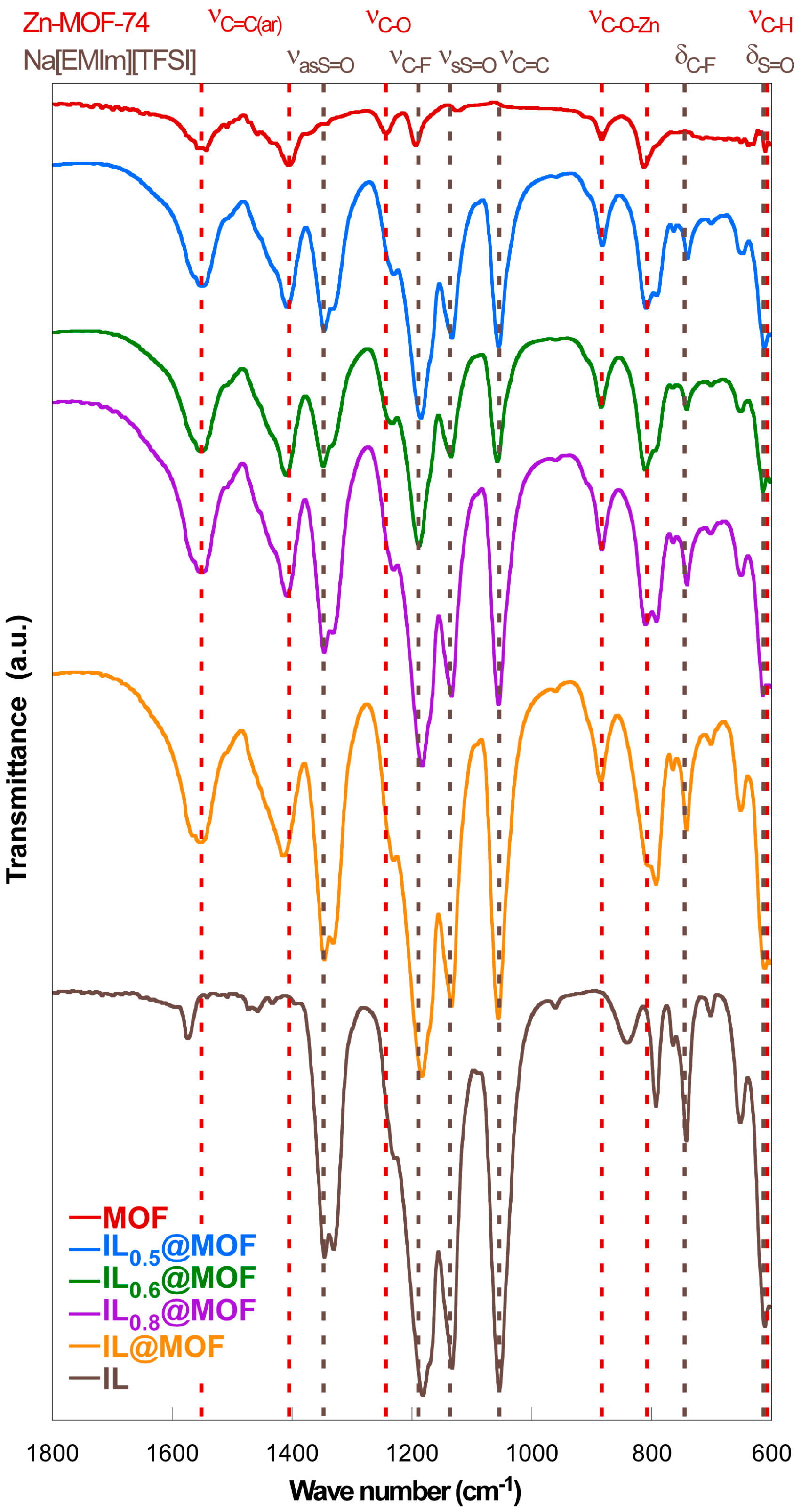
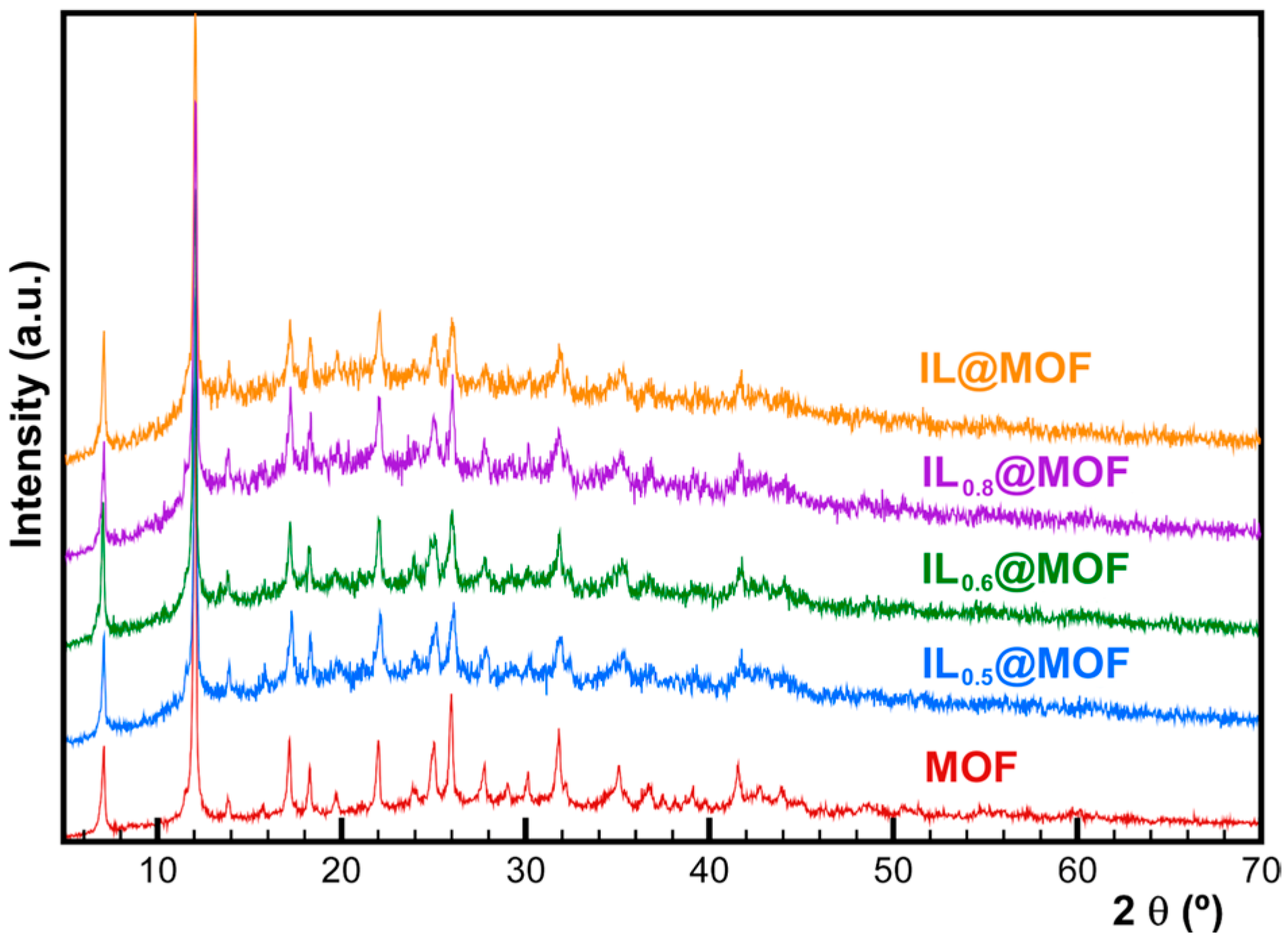
3.1. Physicochemical Characterization

Figure 1 shows the IR absorption spectrum of the activated Zn-MOF-74 (without moisture) with different amounts of ionic liquid (IL@MOF, IL0.8@MOF, IL0.6@MOF and IL0.5@MOF). The characteristic IR bands of the Zn-MOF-74, marked in gray, are the vibration of the C-H bond corresponding to the aromatic ring at 610 cm−1, the vibration of the C-O-Zn at 884 and 804 cm−1 and the bands between 1565 and 1412 cm−1 assigned to the C-C vibration of the aromatic ring in the organic ligand. Finally, the C-O bond vibration bands are observed at 1250 and 1183 cm−1.
Further, the characteristic bands of Na[EMIm][TFSI] are marked in red in Figure 1. As the amount of ionic liquid increases, the size of some bands also increases. In fact, some bonds in the ionic liquid coincide with the ones in Zn-MOF-74. Within the range 500–750 cm−1, two strong stress bands are observed, the first one at 610 cm−1, corresponding to the S=O bending, and the second one corresponding to the C-F bending at 742 cm−1. A band at 1129 cm−1 is observed, ascribed to the S=O strain-symmetric bonding, while another band is also observed at 1331 cm−1, corresponding to an asymmetric a S=O vibration. The observed experimental data are in good agreement with previously published results for Zn-MOF-74 [25] and [EMIm][TFSI] [26].
In order to explore the purity of the synthesized polycrystalline Zn-MOF-74 sample, X-ray diffraction analysis was performed. Figure S1 shows that the phase obtained in the synthesis process for the Zn-MOF-74 compound fits correctly with the cell parameters obtained from the single-crystal data of the compound (a = b = 26.0966; c = 6.6667; α = β = 90°; γ = 120°, GE = R-3) [27]. The fit values are χ2 = 1.36; GoF = 1.20; and Bragg R-factor = 1.25. The excellent fit demonstrates that a pure sample was synthesized.
Once the purity of Zn-MOF-74 was verified, an X-ray diffraction analysis of the Zn-MOF-74 compound with different weight amounts of Na[EMIm][TFSI] ionic liquid was performed (Figure 2).
As can be seen in Figure 2, as the amount of added ionic liquid increases, the intensity of the maximum around 14° increases and the intensity ratios of the most intense maxima (between 7 and 12°) and the maxima between 17 and 20° change. These situations, in addition to the increase in the background signal attributable to the presence of a non-crystalline ionic liquid, allow for the existence of Na[EMIm][TFSI] within the Zn-MOF-74 channels. In addition, analyses of the cell parameters (as shown in Figure S2a) and cell volume (Figure S2b) have been performed. It can be observed that cell parameters a and b decrease slightly due to the electrostatic interactions between the Zn-MOF-74 hexagonal channel walls and the ionic liquid. Parameter c, extending through the hexagonal channel, remains stable. This causes a slight contraction of the cell, with a consequent decrease in volume.
The stability and thermal decomposition of the synthesized compound have been explored via thermogravimetric analysis. Figure 3 shows the thermograms obtained for the Zn-MOF-74 compound and the different amounts of loaded mass ratio of the ionic liquid. In the thermogravimetric curve, two decomposition stages are observed (the first one corresponding to the water loss up to 100 °C and the second from 275 to 445 °C), related to an overlap degradation of Zn-MOF-74 followed by ionic liquid degradation.
As represented in Table S1, as the amount of Na[EMIm][TFSI] in the sample increases, the percentage of water loss decreases since, as the ionic liquid is introduced, less space is left for the water. Furthermore, the percentage of MOF mass loss increases as the ionic liquid percentage increases.
On the other hand, according to data from Kiefer et al., the second stage of decomposition should be between 250 and 400 °C; at higher temperatures, the MOF structure collapses [26]. In the obtained results, a slight deviation from these temperatures is observed. As observed in Table S2, Zn-MOF-74’s decomposition temperature changes when different amounts of ionic liquid have been added. It can be concluded that the samples with ionic liquid present degradation starting temperatures higher than the theoretical ones. This may occur because a percentage of the ionic liquid was also degraded in this range, with the deviation increasing as the ionic liquid content increases.
The surface area of Zn-MOF-74 and the IL0.5@MOF composite has been characterized by N2 physisorption at 77 K (Figure 4). Both samples show very different behavior: while the Zn-MOF-74 sample contains a typical type-I isotherm, the IL0.5@MOF sample contains a type-IV isotherm, corresponding to multilayer adsorption on porous materials and containing a hysteresis cycle due to condensation caused by the irregular shape of the capillaries. Moreover, knowing that Zn-MOF-74 is very porous, it is observed that in the case of the IL0.5@MOF sample, the ionic liquid completely occupies the structural porosity of the MOF.
The BET method was used to obtain the surface area of the Zn-MOF-74 and IL0.5@MOF samples, which were 1123 m2 g−1 and 62 m2 g−1, respectively. It must be considered that in the pristine MOF sample, the porosity is completely empty, and upon introduction of the ionic liquid (sample IL0.5@MOF), the porosity is almost completely lost. This ensures that the ionic liquid is inside the porous structure of the MOF. Table S3 summarizes the fitting parameters obtained from the adsorption data using the AsiQ program.

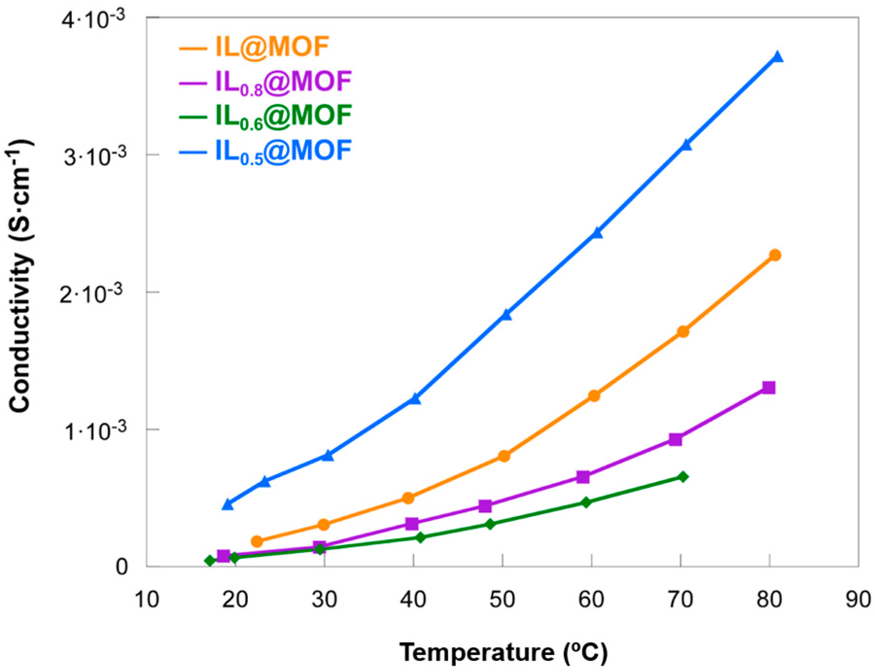
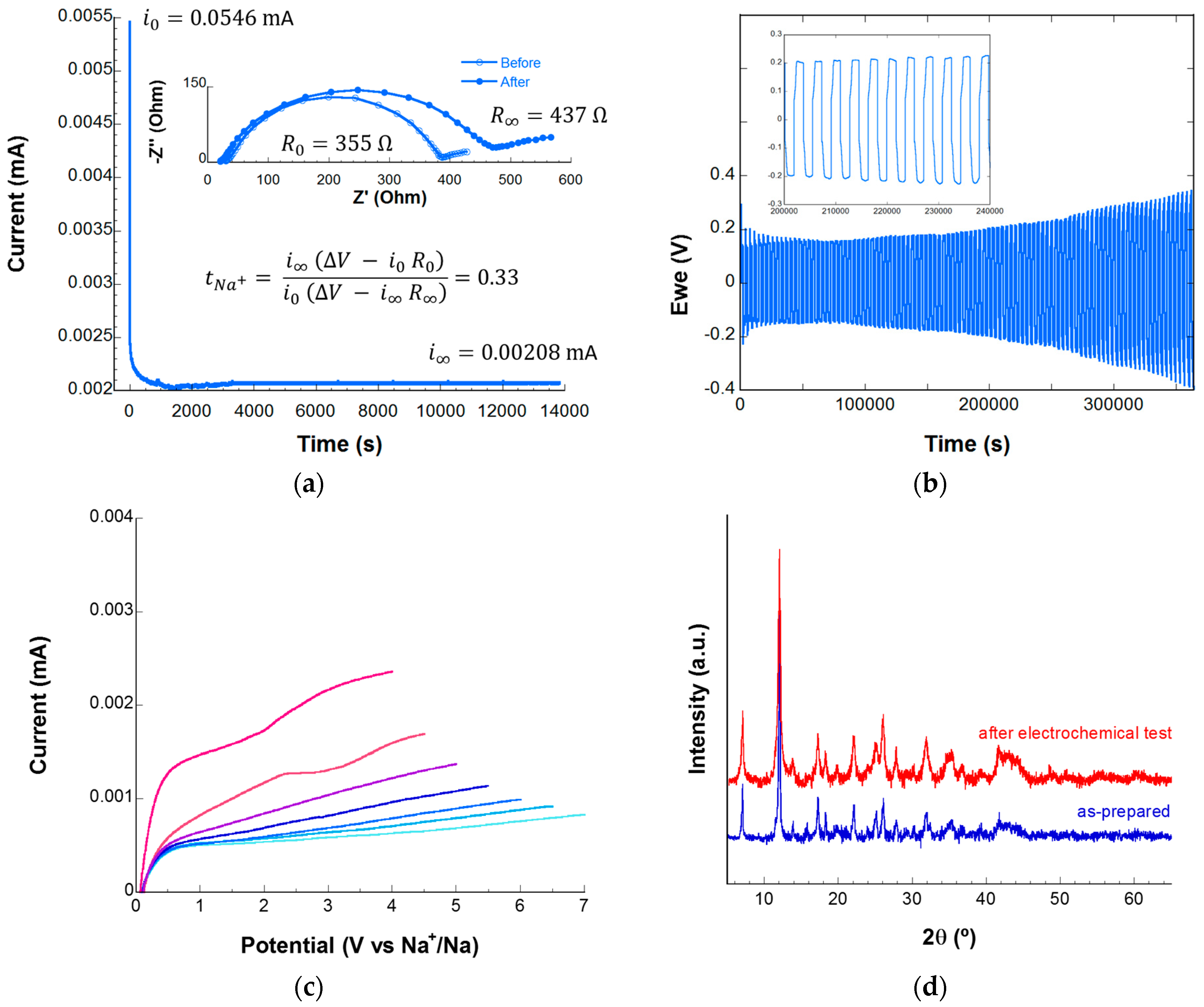
3.2. Electrochemical Characterization

The temperature dependence of the ionic conductivity for the different IL@MOF composites was characterized by electrochemical impedance spectroscopy (EIS), and the recorded spectra between room temperature and 80 °C are shown in Figure S3. At temperatures close to ambient temperature, it is possible to distinguish a characteristic semicircle in the Nyquist diagrams, indicative of conduction through the bulk of the electrolyte. By increasing the temperature, however, only the tail (due to diffusion processes) is observed, in good agreement with the results reported in the literature [28,29,30]. From the resistances associated with the ionic conductivity processes, the conductivity of each sample at different temperatures has been calculated by applying Equation (1). The Zn-MOF-74 compound exhibits negligible ionic conductivity at room temperature (<10−8 S cm−1), but when the ionic liquid is added, this conduction increases by up to five orders of magnitude. Different studies have been published analyzing the anisotropy in conduction through MOF structures [31,32,33]. In the case of Zn-MOF-74, the presence of one-dimensional mesopores in the c-axis of the crystal results in direction-dependent ionic conduction. The electrolytes developed in this work have been prepared from a powder of the Zn-MOF-74 phase with the ionic liquid inserted in the pores. This polycrystalline powder is compacted into a pellet to build the solid electrolyte. The presence of randomly oriented polycrystals throughout the material prevents direction-dependent conduction and eliminates anisotropy in ionic conductivity. Figure 5 represents the conductivity values at different temperatures for the analyzed compounds.
The IL0.5@MOF sample offers the lowest resistance in the temperature range analyzed, with the IL@MOF sample showing the second-lowest resistance among the samples. This evidence allows us to conclude that a higher penetration of the ionic liquid does not always provide a higher ionic conductivity, so in order to achieve a higher ionic mobility, it is critical to explore the optimum ratio between the MOF and the ionic liquid. Concerning the effect of ionic liquid content on ionic conductivity, the trend is not linear. If the IL0.5@MOF sample is not taken into account, the more ionic liquid is added to the composite formulation, the higher the ionic conductivity. This conclusion seems reasonable, since the more segments of the ionic liquid are loaded in the MOF channels, the more charges are available to facilitate the movement of sodium ions. By including the recorded data for sample IL0.5@MOF, this hypothesis is no longer entirely consistent. A theory to explain the excellent behavior of this sample may be related to the interactions between the charged segments of the ionic liquid [34]. An excess of charge can cause the interactions between the segments of the ionic liquid and the sodium ions to be more intense, producing greater difficulty in the mobility of the ions that are more tightly trapped in the channels. Additionally, if the pores become blocked with ionic liquid segments, the movement of the ions would be hindered, resulting in lower ionic conductivity. In this sense, the IL:MOF ratio in the IL0.5@MOF sample is the most appropriate for this system, considering the pore size in the MOF, the dimensions of the ionic liquid segments and the mobility of the ions through the composite.
Table 1 shows the conductivity values obtained in this study at room temperature and 70 °C, along with the values reported by other authors. Compared to the values found in the literature, as far as we are aware, the ionic conductivity of the IL0.5@MOF sample is the best at room temperature for ionic liquid-laden MOF sodium-ion conductors. In fact, the conductivity of MIL-101-SO3Na@Na[EMIm][BF4] is very high, but only when measured at a temperature of 150 °C. Furthermore, comparing the ionic response of the systems developed in this work with that exhibited by conventional ceramic electrolytes, it is possible to conclude that the conductivities achieved by the IL@MOF composites are highly competitive.
In order to analyze the impact of the ionic liquid addition on the ionic movement through the MOF channels, the activation energies related to the ionic conductivity can be a good indicator of the type of mechanism that takes place. These activation energies are calculated using the Arrhenius equation (Equation (2)):
σ = A   e x p E a k   T
where σ is the conductivity obtained from the EIS measurements (S cm−1), A is the pre-exponential term, Ea is the activation energy (eV), k is the Boltzmann constant (8.617 × 10⁻⁵ eV K−1) and T is the absolute temperature (K). From the slope of the linear fit of the Arrhenius plot (Figure 6), the activation energy value for each material can be calculated. The activation energies obtained are similar for all the analyzed samples, being slightly lower in the case of sample IL0.5@MOF. The reported activation energies for similar systems range from 0.2 to 0.3 eV [29,30]. In the case of the IL0.5@MOF sample, the activation energy is similar to that reported by Tuffnell et al. [37]. In the rest of the samples, higher values have been obtained in this work, indicating a greater difficulty in moving the ions. This fact is in good agreement with the existence of stronger electrostatic interactions between the charged species or the reduction in empty space in the pores due to an excess of ionic liquid, hindering the mobility of the ions.
The conduction of sodium ions in electrolytes with solvents is usually explained based on two main mechanisms: the ion-hopping mechanism, in which sodium ions jump through active sites (Grotthuss mechanism), and the vehicle-type mechanism, in which sodium ions are transported together with solvent molecules [38]. As has been evidenced in the study of the ionic conductivity by means of EIS, the Zn-MOF-74 itself does not exhibit true intrinsic ionic conductivity. Indeed, most MOF electrolytes require “activation” by loading the material with a liquid electrolyte salt (sodium-enriched ionic liquid in this research) [39]. MOFs are a type of material with many active centers that can be doped with sodium salts, allowing Na+ ions to be channeled through the ion-hopping mechanism. It is also possible that a hopping mechanism occurs through charged segments of ionic liquid immobilized within the MOF channels. Through chemical interactions, the sodium salt anions and ionic liquid segments can be immobilized on open metal sites of the MOF, so that Na+ ions can easily move through the microporous structure of the MOF. This movement produces ionic conductivity and a high number of sodium ion transfers. When solvents (such as ionic liquids) are introduced into the MOF pores, the conduction of Na+ ions can occur via a vehicle-type mechanism. This type of mechanism is usually associated with higher energy barriers. In the case of the IL@MOF systems developed in this work, both mechanisms can occur simultaneously, although in the case of the IL0.5@MOF sample, the ion-hopping mechanism prevails and a cooperative movement of sodium ions together with segments of the ionic liquid is also possible [40]. By increasing the concentration of ionic liquid, the mobility of the segments is more impeded, which is in good agreement with an increase in the activation energy. In any case, the activation energies obtained are of the same order as those exhibited by other electrolytes of similar composition, even if the most common ceramic compounds in the design of solid electrolytes are taken into account [37].
The total ionic conductivity of the ionic liquid-laden MOF extended solid is derived from the diffusion of all mobile species, including anions, cations and segments from the ionic liquid [39]. Ionic conductivity thus offers an idea of the mobility of ions, both cations and anions, within an electrolyte. On the other hand, the ion transport number, also known as the transference number, is related to the fraction of current that is carried by a given ionic species through an electrolyte. This transport number, although it is influenced by the interactions between the different species within the electrolyte, is a more realistic parameter for analyzing the efficiency of the battery and the rate at which it can be charged and discharged [41,42]. The transference number can be calculated following the potentiostatic polarization method described by Bruce and Vincent [43] by applying a constant potential ( V = 10   mV ) to the material under study using a symmetrical cell with two non-blocking sodium electrodes. This method allows the determination of the transference number for the Na+ ion using Equation (3):
t N a + = i V i 0 R 0 i 0 V i R
where i 0 is the initial current, i is the current in the steady state, R 0 and R are the resistances before and after applying the polarization, respectively, and V is the applied potential. Figure 7a shows the decrease in the initial current (just after applying the polarizing voltage) until reaching the steady state, along with the Nyquist plots recorded before and after perturbation. Using Equation (3), a transference number of 0.33 is obtained, which is considered a more-than-acceptable value compared to those described in the literature for similar systems [14].
The time-dependent voltage profile is presented in Figure 7b. The initial overpotential of 0.2 V increases to 0.4 V after 100 h of operation without observing signs related to short circuits. The IL0.5@MOF material proves to be effective as a dendrite crossover barrier for more than 100 h, with no potential drop observed and stable Na stripping/plating.
The electrochemical stability of the developed solid electrolyte was determined by carrying out LSV measurements at room temperature. The Na/IL0.5@MOF/SS cells were assembled inside the glove box without using any other additive to improve the quality of the interfaces between the MOF-based electrolyte and the sodium metal. The recorded curves are shown in Figure 7c, in which it can be observed that the material is electrochemically stable even at potentials as high as 7 V vs. Na+/Na. This potential is high enough to be able to combine the IL0.5@MOF electrolyte with high-potential cathodes, allowing the development of sodium batteries with a higher energy density [44,45]. The exceptional stability of the developed solid electrolyte is confirmed by postmortem X-ray diffraction measurements (Figure 7d). The diffraction pattern of the material is not distorted even after being subjected to potentials of 7 V vs. Na+/Na. The appearance of new peaks is not observed, nor are there any notable changes when comparing the data recorded before and after the electrochemical test. These results also confirm the stability of the IL0.5@MOF material against metallic sodium.

4. Conclusions

It has been determined that the combination of the Zn-MOF-74 porous metal–organic framework with the sodium-enriched [EMIm][TFSI] ionic liquid leads to obtaining a hybrid material with potential application as a solid electrolyte in sodium batteries. It has been proven that the ionic liquid is effectively introduced into the channels of the porous network of the MOF. In this way, the ionic liquid provides a favorable environment for the mobility of sodium ions through the pores of the MOF, which provides the electrolyte with sufficient structural integrity to act as a barrier against the development of sodium dendrites. Thus, the Na[EMIm][TFSI]@Zn-MOF-74 composites, in addition to presenting excellent structural stability, can tolerate temperatures even above 250 °C without degrading. Furthermore, an optimal IL:MOF ratio of 0.5:1 by weight has been established, capable of exhibiting high ionic conductivities even at room temperature. This fact, together with the high sodium ion transference number, can be attributed to a correct balance between the interactions of the different species within the IL@MOF composite and the occupation of the pores, allowing a more efficient mobility of the sodium ions. This material has been shown to exhibit stability against sodium plating/stripping cycling and is capable of inhibiting the growth of sodium dendrites. In this way, this solid electrolyte, in addition to resisting puncture by sodium dendrites, is compatible with the use of metallic sodium anodes. Finally, an electrochemical stability window of up to 7 V vs. Na+/Na has been determined, which makes this material compatible with the next generation of high-potential sodium cathodes. This study predicts a promising future for this new family of hybrid solid electrolytes towards safer, high-performance and high-energy-density sodium batteries.

Supplementary Materials

The following supporting information can be downloaded at: https://www.mdpi.com/article/10.3390/batteries9120588/s1, Figure S1: Observed, calculated and difference X-ray powder diffraction patterns for compound Zn-MOF-74; Figure S2: (a) Variation in cell parameters as a function of the amount of ionic liquid inserted; (b) variation in the volume as a function of the quantity of IL inserted; Figure S3: EIS spectra of different samples: (a) IL@MOF, (b) IL0.8@MOF, (c) IL0.6@MOF and (d) IL0.5@MOF; Table S1: Parameters corresponding to the decomposition stages in each sample; Table S2: Decomposition temperature range of Zn-MOF-74; Table S3: Adsorption fitting parameters of Zn-MOF-74 and IL0.5@MOF.

Author Contributions

Conceptualization, S.L.-M., A.F.-M. and I.R.d.L.; methodology, E.G., A.F.-M. and I.R.d.L.; validation, E.G., A.F.-M. and I.R.d.L.; formal analysis, A.M.-O., A.F.-M. and I.R.d.L.; investigation, A.M.-O., E.G., A.F.-M. and I.R.d.L.; writing—original draft preparation, A.M.-O., A.F.-M. and I.R.d.L.; writing—review and editing, A.M.-O., E.G., S.L.-M., A.F.-M. and I.R.d.L.; supervision, A.F.-M. and I.R.d.L.; project administration, S.L.-M., A.F.-M. and I.R.d.L.; funding acquisition, S.L.-M. and I.R.d.L. All authors have read and agreed to the published version of the manuscript.

Funding

This work was supported by grant PID2019-107468RB-C21, funded by MCIN/AEI/10.13039/501100011033 and Gobierno Vasco/Eusko Jaurlaritza (project IT1546-22). This study forms part of the Advanced Materials program and was supported by MCIN (with funding from European Union NextGenerationEU (PRTR-C17.I1)) and by the Basque Government (under the IKUR program).

Data Availability Statement

The data presented in this study are available on request from the corresponding author. The data are not publicly available due to privacy.

Acknowledgments

The authors thank the technical and human support provided by SGIker (UPV/EHU/ERDF, EU).

Conflicts of Interest

The authors declare no conflict of interest.

References

  1. Sternberg, A.; Bardow, A. Power-to-What?-Environmental Assessment of Energy Storage Systems. Energy Environ. Sci. 2015, 8, 389–400. [Google Scholar] [CrossRef]
  2. Wang, D.; Liu, N.; Chen, F.; Wang, Y.; Mao, J. Progress and Prospects of Energy Storage Technology Research: Based on Multidimensional Comparison. J. Energy Storage 2024, 75, 109710. [Google Scholar] [CrossRef]
  3. Gutsch, M.; Leker, J. Global Warming Potential of Lithium-Ion Battery Energy Storage Systems: A Review. J. Energy Storage 2022, 52, 105030. [Google Scholar] [CrossRef]
  4. Hossain, M.H.; Chowdhury, M.A.; Hossain, N.; Islam, M.A.; Mobarak, M.H. Advances of Lithium-Ion Batteries Anode Materials—A Review. Chem. Eng. J. Adv. 2023, 16, 100569. [Google Scholar] [CrossRef]
  5. Ma, Q.; Zheng, Y.; Luo, D.; Or, T.; Liu, Y.; Yang, L.; Dou, H.; Liang, J.; Nie, Y.; Wang, X.; et al. 2D Materials for All-Solid-State Lithium Batteries. Adv. Mater. 2022, 34, 2108079. [Google Scholar] [CrossRef] [PubMed]
  6. Raj, V.; Phani, N.; Aetukuri, B.; Nanda, J. Solid State Lithium Metal Batteries—Issues and Challenges at the Lithium-Solid Electrolyte Interface. Curr. Opin. Solid State Mater. Sci. 2022, 26, 100999. [Google Scholar] [CrossRef]
  7. Wu, F.; Maier, J.; Yu, Y. Rechargeable Lithium and Lithium-Ion Batteries. Chem. Soc. Rev. 2020, 49, 1569–1614. [Google Scholar] [CrossRef]
  8. Goikolea, E.; Palomares, V.; Wang, S.; Ruiz de Larramendi, I.; Guo, X.; Wang, G.; Rojo, T. Na-Ion Batteries—Approaching Old and New Challenges. Adv. Energy Mater. 2020, 10, 2002055. [Google Scholar] [CrossRef]
  9. Feng, J.; An, Y.; Ci, L.; Xiong, S. Nonflammable Electrolyte for Safer Non-Aqueous Sodium Batteries. J. Mater. Chem. A 2015, 3, 14539–14544. [Google Scholar] [CrossRef]
  10. Wang, L.; Li, J.; Lu, G.; Li, W.; Tao, Q.; Shi, C.; Jin, H.; Chen, G.; Wang, S. Fundamentals of Electrolytes for Solid-State Batteries: Challenges and Perspectives. Front. Mater. 2020, 7, 111. [Google Scholar] [CrossRef]
  11. He, Y.; Qiao, Y.; Chang, Z.; Zhou, H. The Potential of Electrolyte Filled MOF Membranes. Energy Environ. Sci. 2019, 12, 2327–2344. [Google Scholar] [CrossRef]
  12. Jiang, Y.; Zhao, H.; Yue, L.; Liang, J.; Li, T.; Liu, Q.; Luo, Y.; Kong, X.; Lu, S.; Shi, X.; et al. Electrochemistry Communications Recent Advances in Lithium-Based Batteries Using Metal Organic Frameworks as Electrode Materials. Electrochem. Commun. 2021, 122, 106881. [Google Scholar] [CrossRef]
  13. Zhao, R.; Liang, Z.; Zou, R.; Xu, Q. Metal-Organic Frameworks for Batteries. Joule 2018, 2, 2235–2259. [Google Scholar] [CrossRef]
  14. Urgoiti-Rodriguez, M.; Vaquero-Vílchez, S.; Mirandona-Olaeta, A.; Fernández de Luis, R.; Goikolea, E.; Costa, C.M.; Lanceros-Mendez, S.; Fidalgo-Marijuan, A.; Ruiz de Larramendi, I. Exploring Ionic Liquid-Laden Metal-Organic Framework Composite Materials as Hybrid Electrolytes in Metal (Ion) Batteries. Front. Chem. 2022, 10, 995063. [Google Scholar] [CrossRef] [PubMed]
  15. Sahoo, S.; Kumar, R.; Dhakal, G.; Shim, J.J. Recent Advances in Synthesis of Metal-Organic Frameworks (MOFs)-Derived Metal Oxides and Its Composites for Electrochemical Energy Storage Applications. J. Energy Storage 2023, 74, 109427. [Google Scholar] [CrossRef]
  16. Shahzad, U.; Marwani, H.M.; Saeed, M.; Asiri, A.M.; Althomali, R.H.; Rahman, M.M. Exploration of Porous Metal-Organic Frameworks (MOFs) for an Efficient Energy Storage Applications. J. Energy Storage 2023, 74, 109518. [Google Scholar] [CrossRef]
  17. Huo, H.; Wu, B.; Zhang, T.; Zheng, X.; Ge, L.; Xu, T. Anion-Immobilized Polymer Electrolyte Achieved by Cationic Metal-Organic Framework Fi Ller for Dendrite-Free Solid-State Batteries. Energy Storage Mater. 2019, 18, 59–67. [Google Scholar] [CrossRef]
  18. Shalaby, M.S.; Alziyadi, M.O.; Gamal, H.; Hamdy, S. Solid-State Lithium-Ion Battery: The Key Components Enhance the Performance and Efficiency of Anode, Cathode, and Solid Electrolytes. J. Alloys Compd. 2023, 969, 172318. [Google Scholar] [CrossRef]
  19. Liu, K.; Wang, Z.; Shi, L.; Jungsuttiwong, S.; Yuan, S. Ionic Liquids for High Performance Lithium Metal Batteries. J. Energy Chem. 2021, 59, 320–333. [Google Scholar] [CrossRef]
  20. Guglielmero, L.; Mero, A.; Mezzetta, A.; Tofani, G.; D’Andrea, F.; Pomelli, C.S.; Guazzelli, L. Novel Access to Ionic Liquids Based on Trivalent Metal–EDTA Complexes and Their Thermal and Electrochemical Characterization. J. Mol. Liq. 2021, 340, 117210. [Google Scholar] [CrossRef]
  21. Hakim, L.; Ishii, Y.; Matsumoto, K.; Hagiwara, R.; Ohara, K.; Umebayashi, Y.; Matubayasi, N. Transport Properties of Ionic Liquid and Sodium Salt Mixtures for Sodium-Ion Battery Electrolytes from Molecular Dynamics Simulation with a Self-Consistent Atomic Charge Determination. J. Phys. Chem. B 2020, 124, 7291–7305. [Google Scholar] [CrossRef]
  22. Majid, M.F.; Zaid, H.F.M.; Kait, C.F.; Ahmad, A.; Jumbri, K. Ionic Liquid@Metal-Organic Framework as a Solid Electrolyte in a Lithium-Ion Battery: Current Performance and Perspective at Molecular Level. Nanomaterials 2022, 12, 1076. [Google Scholar] [CrossRef]
  23. Feng, L.; Li, G.Q.; Li, Y.K.; Gu, X.L.; Hu, S.Y.; Han, Y.C.; Wang, Y.F.; Zheng, J.C.; Deng, Y.H.; Wan, C.Q. MOF-Supported Crystalline Ionic Liquid: New Type of Solid Electrolyte for Enhanced and High Ionic Conductivity. Dalt. Trans. 2022, 51, 6086–6094. [Google Scholar] [CrossRef]
  24. Roisnel, T.; Rodriguez-Carvajal, J. WinPLOTR: A Windows Tool for Powder Diffraction Pattern Analysis. Mater. Sci. Forum 2001, 378, 118–123. [Google Scholar] [CrossRef]
  25. Zhang, C.N.; Li, Y.; Fan, H.L.; Yang, C.; Wu, M.M. A Highly Reversible Sorption for Sulfur-Containing Toxic VOCs Emissions Under Ambient Temperature and Pressure. J. Inorg. Organomet. Polym. Mater. 2020, 30, 486–493. [Google Scholar] [CrossRef]
  26. Kiefer, J.; Fries, J.; Leipertz, A. Experimental Vibrational Study of Imidazolium-Based Ionic Liquids: Raman and Infrared Spectra of 1-Ethyl-3methylimidazolium Bis(Trifluoromethylsulfonyl) Imide and 1-Ethyl-3-Methylimidazolium Ethylsulfate. Appl. Spectrosc. 2007, 61, 1306–1311. [Google Scholar] [CrossRef]
  27. Rosi, N.L.; Kim, J.; Eddaoudi, M.; Chen, B.; O’Keeffe, M.; Yaghi, O.M. Rod Packings and Metal-Organic Frameworks Constructed from Rod-Shaped Secondary Building Units. J. Am. Chem. Soc. 2005, 127, 1504–1518. [Google Scholar] [CrossRef]
  28. Yang, H.; Abdullah, M.; Bright, J.; Hu, W.; Kittilstved, K.; Xu, Y.; Wang, C.; Zhang, X.; Wu, N. Polymer-Ceramic Composite Electrolytes for All-Solid-State Lithium Batteries: Ionic Conductivity and Chemical Interaction Enhanced by Oxygen Vacancy in Ceramic Nanofibers. J. Power Sources 2021, 495, 229796. [Google Scholar] [CrossRef]
  29. Yu, X.; Grundish, N.S.; Goodenough, J.B.; Manthiram, A. Ionic Liquid (IL) Laden Metal-Organic Framework (IL-MOF) Electrolyte for Quasi-Solid-State Sodium Batteries. ACS Appl. Mater. Interfaces 2021, 13, 24662–24669. [Google Scholar] [CrossRef]
  30. Nozari, V.; Calahoo, C.; Tuffnell, J.M.; Adelhelm, P.; Wondraczek, K.; Dutton, E.; Bennett, T.D.; Wondraczek, L. Sodium Ion Conductivity in Superionic IL-Impregnated Metal-Organic Frameworks: Enhancing Stability Through Structural Disorder. Sci. Rep. 2020, 10, 3532. [Google Scholar] [CrossRef]
  31. Goswami, S.; Hod, I.; Duan, J.D.; Kung, C.W.; Rimoldi, M.; Malliakas, C.D.; Palmer, R.H.; Farha, O.K.; Hupp, J.T. Anisotropic Redox Conductivity within a Metal-Organic Framework Material. J. Am. Chem. Soc. 2019, 141, 17696–17702. [Google Scholar] [CrossRef] [PubMed]
  32. Pratik, S.M.; Gagliardi, L.; Cramer, C.J. Engineering Electrical Conductivity in Stable Zirconium-Based PCN-222 MOFs with Permanent Mesoporosity. Chem. Mater. 2020, 32, 6137–6149. [Google Scholar] [CrossRef]
  33. Zhang, S.; Zhang, W.; Yadav, A.; Baker, J.; Saha, S. From a Collapse-Prone, Insulating Ni-MOF-74 Analogue to Crystalline, Porous, and Electrically Conducting PEDOT@MOF Composites. Inorg. Chem. 2023, 62, 18999–19005. [Google Scholar] [CrossRef]
  34. Wei, Y.; Dong, Y.; Ji, X.; Ullah Shah, F.; Laaksonen, A.; An, R.; Riehemann, K. Detailing Molecular Interactions of Ionic Liquids with Charged SiO2 Surfaces: A Systematic AFM Study. J. Mol. Liq. 2022, 350, 118506. [Google Scholar] [CrossRef]
  35. Fertig, M.P.; Skadell, K.; Schulz, M.; Dirksen, C.; Adelhelm, P.; Stelter, M. From High- to Low-Temperature: The Revival of Sodium-Beta Alumina for Sodium Solid-State Batteries. Batter. Supercaps 2022, 5, e202100131. [Google Scholar] [CrossRef]
  36. Xu, Q.; Yang, F.; Zhang, X.; Li, J.R.; Chen, J.F.; Zhang, S. Combining Ionic Liquids and Sodium Salts into Metal-Organic Framework for High-Performance Ionic Conduction. ChemElectroChem 2020, 7, 183–190. [Google Scholar] [CrossRef]
  37. Tuffnell, J.M.; Morzy, J.K.; Kelly, N.D.; Tan, R.; Song, Q.; Ducati, C.; Bennett, T.D.; Dutton, S.E. Comparison of the Ionic Conductivity Properties of Microporous and Mesoporous MOFs Infiltrated with a Na-Ion Containing IL Mixture. Dalt. Trans. 2020, 49, 15914–15924. [Google Scholar] [CrossRef] [PubMed]
  38. Lourenço, T.C.; Dias, L.G.; Da Silva, J.L.F. Theoretical Investigation of the Na+Transport Mechanism and the Performance of Ionic Liquid-Based Electrolytes in Sodium-Ion Batteries. ACS Appl. Energy Mater. 2021, 4, 4444–4458. [Google Scholar] [CrossRef]
  39. Kharod, R.A.; Andrews, J.L.; Dinca, M. Teaching Metal-Organic Frameworks to Conduct: Ion and Electron Transport in Metal-Organic Frameworks. Annu. Rev. Mater. Res. 2022, 52, 103–128. [Google Scholar] [CrossRef]
  40. Yang, H.; Wu, N. Ionic Conductivity and Ion Transport Mechanisms of Solid-State Lithium-Ion Battery Electrolytes: A Review. Energy Sci. Eng. 2022, 10, 1643–1671. [Google Scholar] [CrossRef]
  41. Fang, C.; Mistry, A.; Srinivasan, V.; Balsara, N.P.; Wang, R. Elucidating the Molecular Origins of the Transference Number in Battery Electrolytes Using Computer Simulations. JACS Au 2023, 3, 306–315. [Google Scholar] [CrossRef] [PubMed]
  42. Zugmann, S.; Fleischmann, M.; Amereller, M.; Gschwind, R.M.; Wiemhöfer, H.D.; Gores, H.J. Measurement of Transference Numbers for Lithium Ion Electrolytes via Four Different Methods, a Comparative Study. Electrochim. Acta 2011, 56, 3926–3933. [Google Scholar] [CrossRef]
  43. Evans, J.; Vincent, C.A.; Bruce, P.G. Electrochemical Measurement of Transference Numbers in Polymer Electrolytes. Polymer 1987, 28, 2324–2328. [Google Scholar] [CrossRef]
  44. You, Y.; Manthiram, A. Progress in High-Voltage Cathode Materials for Rechargeable Sodium-Ion Batteries. Adv. Energy Mater. 2018, 8, 1701785. [Google Scholar] [CrossRef]
  45. Shipitsyn, V.; Jayakumar, R.; Zuo, W.; Sun, B.; Ma, L. Understanding High-Voltage Behavior of Sodium-Ion Battery Cathode Materials Using Synchrotron X-Ray and Neutron Techniques: A Review. Batteries 2023, 9, 461. [Google Scholar] [CrossRef]
Figure 1. Infrared absorption spectra of Zn-MOF-74, Na[EMIm][TFSI] and the four ILx@MOF compounds. IR bands corresponding to Zn-MOF-74 are marked by red dashed lines, and the bands corresponding to Na[EMIm][TFSI] are marked by gray dashed lines.
Batteries 09 00588 g001
Figure 2. XRD patterns of Zn-MOF-74 with different amounts of ionic liquid.
Batteries 09 00588 g002
Figure 3. Thermogravimetric analysis of Zn-MOF-74 and the corresponding ionic liquid composites. Colored lines indicate mass loss, and dashed lines indicate DSC.
Batteries 09 00588 g003
Figure 4. N2 adsorption–desorption isotherms for Zn-MOF-74 in red and IL0.5@MOF in blue.
Batteries 09 00588 g004
Figure 5. Temperature dependence of the ionic conductivity of the studied samples with different amounts of ionic liquid.
Batteries 09 00588 g005
Figure 6. Arrhenius plot of the conductivity vs. the inverse of the temperature for obtaining the activation energy of each composite material.
Batteries 09 00588 g006
Figure 7. (a) Chronoamperometry profile and initial and steady-state impedance diagrams of the IL0.5@MOF sample; (b) galvanostatic cycling profile of symmetric Na/IL0.5@MOF/Na at current densities of 0.1 mA cm−2 at room temperature; (c) linear sweep voltammetry (LSV) profiles of the Na/IL0.5@MOF/SS cell recorded at a scan rate of 1 mV s−1; and (d) diffractograms corresponding to the IL0.5@MOF electrolyte as it was prepared and after the LSV measurement.
Batteries 09 00588 g007
Table 1. Conductivities recorded at room temperature (RT) and 70 °C for each IL@MOF sample, together with experimental results extracted from the literature.
SampleT (°C)σ (S cm−1)Reference
Na-β″-aluminaRT1.7 × 10−3[35]
Na3Zr2Si2PO12RT2.1 × 10−3[8]
IL@MOF22.41.83 × 10−3This work
70.31.71 × 10−3
IL0.8@MOF18.67.93 × 10−3
69.49.3 × 10−3
IL0.6@MOF17.14.55 × 10−3
70.36.55 × 10−3
IL0.5@MOF19.14.58 × 10−3
70.63.1 × 10−3
[Na0.1EMIm0.9][TFSI]@ZIF-8RT crystalline2.97 × 10−3[30]
RT amorphous2.0 × 10−3
Na[Bmpyr][TFSI]@ UiO-66-SO3NaRT3.6 × 10−3[29]
NaTFSI-EIMS@UiO-67-MIMS301.24 × 10−3[23]
Na[EMIm][BF4]@MIL-101-SO3Na1501.32 × 10−3[36]
Na[EMIm][TFSI]@ZIF-8RT (ZIF-8micro)1.6 × 10⁻³[37]
RT (ZIF-8meso)8.4 × 10⁻³
Disclaimer/Publisher’s Note: The statements, opinions and data contained in all publications are solely those of the individual author(s) and contributor(s) and not of MDPI and/or the editor(s). MDPI and/or the editor(s) disclaim responsibility for any injury to people or property resulting from any ideas, methods, instructions or products referred to in the content.

