
Impact of Surface Structure on SEI for Carbon Materials in Alkali Ion Batteries: A Review
by
Xvtong Zhao
1,
Ying Chen
1,
Hao Sun
1,
Tao Yuan
1,
Yinyan Gong
2,
Xinjuan Liu
1 and
Taiqiang Chen
1,* 1
School of Materials Chemistry, University of Shanghai for Science and Technology, Shanghai 200093, China
2
Key Laboratory of Rare Earth Optoelectronic Materials and Devices of Zhejiang Province, College of Optical and Electronic Technology, China Jiliang University, Hangzhou 310020, China
*
Author to whom correspondence should be addressed.
Batteries 2023, 9(4), 226; https://doi.org/10.3390/batteries9040226
Submission received: 14 March 2023
/
Revised: 1 April 2023
/
Accepted: 12 April 2023
/
Published: 14 April 2023
(This article belongs to the Special Issue Review of Electrode Materials and Electrolyte for Batteries)
Abstract
:Due to their low cost, suitable working potential and high stability, carbon materials have become an irreplaceable anode material for alkali ion batteries, such as lithium ion batteries, sodium ion batteries and potassium ion batteries. During the initial charge, electrolyte is reduced to form a solid electrolyte interphase (SEI) on the carbon anode surface, which is an electron insulator but a good ion conductor. Thus, a stable surface passivation is obtained, preventing the decomposition of electrolyte in the following cycles. It has been widely accepted that SEI is essential for the long-term performance of batteries, such as calendar life and cycle life. Additionally, the initial coulombic efficiency, rate capability as well as safety of the batteries are dramatically influenced by the SEI. Extensive research efforts have been made to develop advanced SEI on carbon materials via optimization of electrolytes, including solutes, solvents and additives, etc. However, SEI is produced via the catalytic decomposition of electrolyte by the surface of electrode materials. The surface structure of the carbon material is another important aspect that determines the structure and property of SEI, which little attention has been paid to in previous years. Hence, this review is dedicated to summarizing the impact of the surface structure of carbon materials on the composition, structure and electrochemical performance of the SEI in terms of surface atoms exposed, surface functionalization, specific surface area and pore structure. Some insights into the future development of SEI from the perspective of carbon surface are also offered.
1. Introduction
The growing concerns with regard to environment and sustainability have promoted the development of renewable energy resources, such as wind and solar energy [1]. Due to the intermittent nature of these renewable energy sources, the development of energy storage devices has become an actual necessity. Alkali ion batteries, such as lithium ion batteries (LIBs), sodium ion batteries (SIBs) and potassium ion batteries (PIBs), are considered as promising energy storage devices because of their high energy and power densities. Particularly, SIBs receive great attention as the next generation low cost alternative by virtue of abundant sodium resources [2,3,4]. In addition, the abundance of potassium in the crust is close to that of sodium, and the redox potential of K+/K (−2.92 V) is similar to that of lithium and much lower than that of Na+/Na at −2.714 V. Therefore, PIBs have also greatly attracted the interest of researchers [5,6]. At present, a series of anode materials such as carbon and derivatives, oxides and alloys [7,8] have been exploited. Nevertheless, carbon materials, due to their low cost, suitable working potential and high stability, were always the first choice for anode materials since the first generation of commercial LIBs was developed. Graphite has already made a wide and profound impact as the first generation of commercial anode materials. Additionally, hard carbon is considered to be the most promising and probably the only alternative anode material for SIBs, as sodium ions could not be inserted due to the narrow layer spacing of graphite [9]. Hard carbon can exhibit a high capacity benefiting from its expanded interplanar spacing and significant porosity for ion accommodation. However, carbon anode materials still suffer from drawbacks such as low initial coulombic efficiency (ICE) and sluggish rate capability in many practical applications [10,11,12].
During the operation of alkali ion batteries, a solid electrolyte interphase (SEI) forms on the carbon material surface rising from the decomposition of electrolyte at low potential, which is beyond its stable window [13]. It has been widely accepted that SEI is essential to alkali metal-ion batteries and the initial coulombic efficiency (ICE), calendar life, cycle life, rate capability as well as safety of the batteries are dramatically influenced by it [14,15,16,17,18]. Therefore, it is vital to control its formation and growth with suitable chemical composition, morphology and stability, so as to maintain a good passivating and electrochemical stability over long-term cycling. Researchers have extensively worked on the formulation of electrolytes, including solutes, solvents and additives, etc., aiming to obtain an advanced SEI on carbon materials. Some excellent reviews have summarized the research progress of SEI for carbon materials with a focus on the impact of electrolytes [19,20,21]. SEI is produced via the catalytic decomposition of electrolyte by the electrode material surface. Aspects including electrode material (surface), electrolyte and the conditions of its formation are crucial to the formation and growth of SEI [22,23], as schematically summarized in Figure 1. The surface structure of the carbon material is also one of the most important factors that determines the structure and property of SEI. Therefore, it is necessary to review and summarize the research progress of SEI with an emphasis of the surface structure. Hence, this review is dedicated to summarizing the impact of surface structure of carbon materials on the composition, structure and electrochemical performance of the SEI in terms of surface atoms exposed, surface functionalization, specific surface area and pore structure. A brief introduction to SEI on carbon concerning its structure and composition as well as the common modification strategy based on electrolyte is given first. Then, we analyze and discuss how the surface structure of carbon can influence and improve the formation and properties of SEI in detail. Finally, some insights into the future development of SEI from the perspective of carbon surface are offered.
2. An Overview of SEI
Electrolytes can maintain their stability within a certain voltage range, which is the electrochemical window (ECW) of the electrolyte. The reduction potential of organic electrolyte commonly used in Li-ion batteries is about 1.0 V vs. Li+/Li [24], while the potential of lithium-inserted carbon materials is about 0–0.25 V vs. Li+/Li, which is exceeding much lower than the reduction potential of the electrolyte. On the other hand, the reduction potentials of organic electrolytes commonly used in SIBs and PIBs are about 0.7 V vs. Na+/Na and 0.9 V vs. K+/K [25]. Therefore, the electrolyte decomposes and is deposited on the electrode surface to form SEI during the insertion process. An ideal SEI has to satisfy the following requirements [26]: (1) isolation of electrons and conduction of ions and (2) excellent stability, such as mechanical stability, chemical stability and thermal stability, etc. SEI plays a crucial role in determining many of the electrochemical performances of the battery. The isolation of electrons prevents the continuous decomposition of the electrolyte and the continuous thickening of the SEI; a high ionic conductivity contributes to the rate performance; and its excellent stability ensures the cycle life and calendar life of the battery. Additionally, the properties of SEI are highly correlated with its structure and composition.
2.1. Structure and Composition of SEI
Commercial lithium-ion batteries rely on graphite as the anode material; the commonly used carbonic ester electrolyte will be decomposed by graphite at its low working potential, which is a complex process [27]. The decomposition products form the SEI, which has been studied and elaborated in numerous works over the past decades, and knowledge on the morphology, structure, composition and properties of SEI accumulated gradually. In the 1970s, surface films formed on the surface of lithium metal immersed in organic electrolyte were observed by microscopy [28]. The concept of SEI on alkali and alkaline earth metals was first proposed by Peled in 1979 [29]. However, specific information on the structure and composition of SEI was not characterized in detail due to the lack of available characterization tools at the time. With the development of characterization tools, the understanding of SEI progressively deepened.
Based on the electrochemical impedance spectroscopy (EIS) and Fourier transform infrared spectroscopy (FTIR) results, Zaban et al. [30] drew a conclusion that SEI is a multilayered structure consisting of a dense inorganic inner layer and a porous organic outer layer. SEI was further depicted as a mosaic structure in which the salt was deposited in separate clumps and the contribution of grain boundaries to the total impedance of SEI was emphasized by Peled et al. [31]. Since then, the notion that SEI is a multilayer film with each layer forming a mosaic structure was widely accepted. Clear evidence was reported by Zheng et al. [32] who showed 3D multilayer SEI structures on silicon electrodes using in situ atomic force microscopy (AFM). Wu et al. [26] summarized the timeline in explorations of SEI, as shown in Figure 2.
The main components of SEI include both inorganic and organic parts [33]. The dense inorganic layer lies in the inner side, close to the electrode, and consists of inorganic lithium salts in the low oxidation state such as Li2CO3, Li2O, LiF, Li3N, LiCl and LiOH. The porous organic layer is on the outer side, close to the electrolyte, and consists of organic compounds in a higher oxidation state, such as (CH2OCO2Li)2, ROCOOLi and ROLi (R-organic groups associated with solvent molecules) [34]. However, the structure of the SEI layer is more complex than described [32,35,36,37]. Two different mechanisms of ion migration in SEI have been found. One is the rapid pore diffusion in the organic layer, during which the solventized ions gradually break away from their solvent molecules. The other is knock-off diffusion in the dense inorganic layer, where ions diffuse through a repetitive interstitial stripping mechanism and eventually reach the electrode surface [33].
2.2. Effect of Electrolyte on SEI
The composition and structure of SEI depend on various aspects, including electrolyte composition, temperature, current density, etc. Among them, reduction and decomposition due to thermodynamic instability and kinetic reactions of the electrolyte constitute the components of the SEI layer, which has been extensively investigated. The decomposition products of various solvents depend on parameters of the solvent such as dielectric constant, polarity, reactivity and viscosity. Cyclic carbonates, such as ethylene carbonate (EC) and propylene carbonate (PC), are widely used solvents because of their high dielectric constants and good electrochemical stability [38]. PC became the focus of research as early as 1958 when it was observed that lithium could be electrodeposited out of LiClO4 in PC solution. However, capacity degradation of PC electrolyte-based lithium batteries is inevitable because of multiple mechanisms [39], as reflected by the low lithium plating/stripping efficiency below ≤85% during cycling. EC has a higher dielectric constant than PC, but it was never used as a room temperature electrolyte in early studies because EC is solid at room temperature. It was not until Pistoia et al. [40,41] reported that the presence of solute, such as dimethyl carbonate (DMC), reduces the melting point and therefore results in a room temperature melt. Further studies [41] revealed that the superiority of EC-based electrolytes as compared with PC was also found in the low interface impedance and stable SEI that suppressed the exfoliation of graphite layer [42]. SEI derived from ether-based electrolytes, such as diethylene glycol dimethyl ether, was found to be thinner and stiffer than its EC/DMC counterpart [43]. Nevertheless, ester solvents were usually the better choice as compared to ether solvents that exhibit low oxidation potential, high cost, high flammability and poor compatibility with high voltage cathodes.
The composition and structure of SEI are significantly affected by the salt because the anion of the electrolyte salt decomposes at low potentials and participates in the formation of SEI [37,44]. LiClO4 is a favored electrolyte salt due to its high conductivity and high anodic stability, but perchlorate is a strong oxidant that tends to react with most organics at high temperatures and high currents. LiAsF6 is superior to LiClO4 as an electrolyte solute. However, a major obstacle to commercialization is that As (0) and As (III) are toxic. Additionally, it has been proven that LiAsF6 reacts with the solvent [45]. When LiAsF6 was used in a study as the electrolyte salt, the SEI produced contained a large amount of organic compounds, such as alkyl carbonate. LiPF6 is not the most outstanding in a single aspect of properties but maintains a well-balanced performance among all aspects while meeting multiple requirements. The SEI derived from the electrolyte with LiPF6 contains more LiF components.
Moreover, electrolyte additives, with higher reduction potential than solvents or salts, are preferentially decomposed to form a passivating film prior to electrolyte reduction. This film not only reduces the decomposition of the electrolyte, but also facilitates the construction of a stable SEI. Various additives have been explored and used in batteries, with vinylidene carbonate (VC) [46] and fluoroethylene carbonate (FEC) [47,48] being the most widely applied. Although the presence of additives improves the formation of SEI to some extent, which is mainly reflected in the generation of stable SEI, at the same time, the additives may have negative effects or incompatibility. For example, the addition of VC decreases the sodium storage capacity [49], although it was not observed in Li-ion batteries [50]. The addition of FEC increases the interface impedance of the electrode [18,51].
3. Effect of Carbon Surface on SEI
3.1. Surface Atoms Exposed
Carbon materials prepared by the pyrolysis of organic compounds can usually be divided into two main categories: graphitizable and non-graphitizable carbon [52]. The most important structural difference between graphitizable and non-graphitizable carbon is the nano-texture. The former has a relatively well orientated graphitic domain, while the latter has a randomly oriented nanotexture of graphitic nano-domains and contains a large number of micropores. Increasing heat treatment temperature leads to the growth of crystal size with expansion and stacking of graphitic layers. For non-graphitizable carbon, the crystal growth is limited by the local orientation, even at high temperatures above 3000 °C. Thus, non-graphitized carbon, often described as hard carbon (HC), has low graphitization, low apparent density and high porosity. In general, HC is amorphous and cannot be graphitized even at very high temperatures. On the contrary, soft carbon, which can also be referred to as graphitizable carbon, has an ordered structure. Artificial graphite with good crystal structure can be obtained after graphitization of soft carbon. Graphite has a layered structure consisting of sp2 hybridized carbon of a hexagonal packing. Hexagonal graphite or rhombic graphite is formed by the orderly stacking of carbon layers in different rules [53]. While hard carbon does not have a long-range ordered structure with planar extensions or carbon layer stacks, it is characterized by randomly arranged sp2 graphitic microregions that are partially cross-linked with amorphous regions of sp3 hybridized carbon atoms. Different topologies lead to diverse electrochemical behaviors of the materials. Additionally, the exposure of a distinct crystal surface has an important impact on the catalytic production of SEI on it [54].
Highly oriented pyrolytic graphite (HOPG) is a kind of “crystalline” graphite with good crystalline structure, excellent orientation and a high degree of graphitization. Time-of-flight secondary-ion mass spectrometry (TOF SIMS) and X-ray photoelectron spectroscopy (XPS) measurements were carried out for SEI formed on the different planes of HOPG [55]. The SEI on both the basal planes (carbon layer extension direction) and cross-sectional (edge) planes (carbon layer stacking direction) are present with C2H (or other CxHy-based fragments), O, C2H3O2 and C2H3O, which cover the material surface intactly and show a fairly high degree of homogenization. The SEI on the basal plane is dominated by organic matter, with oxygen and C2H3O being the main components. Lithium and fluorine are concentrated in a large region (100 μm), with some smaller micron-sized particles as well [56]. The distinctive feature of the basal SEI is the presence of 10 to 30 atomic% Li2CO3 on the surface and in the bulk. The SEI on the edge plane consisted mainly of lithium and fluorine with a Li/F ratio close to one, but there are also regions of one to several tens of microns in size where both elements are almost absent. Moreover, E. Peled et al. [57] showed that the thickness of SEI on the basal plane is thinner relative to that on the edge plane. SEI thickness measured by XPS is 7 nm for basal-SEI and 35 nm for edge plane SEI. Thick SEI at the edge plane was explained by hydrogen permeation and solvent co-intercalation and exfoliation. A study reported by Eshkenazi et al. [58] showed a possible co-intercalation layer of protons as HF dissociation products, resulting in a thick SEI. Partial exfoliation of graphite by Li2PF6+ and hydrogen permeation may cause an increase in SEI thickness, which is similar to the results on HOPG cross section in LiPF6 electrolyte. The content of PO3− species on the edge plane was three times higher than that on the basal plane revealed by TOF SIMS. This clearly shows that the exchange current density for LiPF6 (and HF) reduction is much higher at the cross section than that at the basal plane. Comparing the SEI formed on disordered carbon and HOPG, the SEI formed on hard carbon is more similar to the SEI of HOPG on edge plane, while the SEI formed on soft carbon is more similar to the basal SEI of HOPG as shown in Figure 3a–d [59]. The reason may be that the structure of carbon materials contains a large number of off-domain π-bonds containing electrons that can move freely. During the electrochemical process, the applied voltage drives the electrons to move from the electrode to the electrolyte, thus promoting the decomposition of the electrolyte.
Based on the above findings, Oka et al. [60] coated a layer of amorphous carbon on the graphite anode surface as an LIB anode, named coated in Figure 3e–h, and graphite was named pristine. The amorphous carbon improved the uniform crystallinity of the graphite surface structure and suppressed the massive decomposition of the electrolyte at the edge planes. As shown in Figure 3g, this layer of amorphous carbon reduced the amount of SEI formed below 1 V vs. Li+/Li, thereby increasing the ICE to 87.7%. In addition, as shown in Figure 3e,f, the SEI produced on the amorphous carbon surface has more lithium carbonate and lithium fluoride, improving the stability of the SEI at the edge planes. Figure 3h shows the schematic diagram of SEI without and with the amorphous carbon layer.
The influence of active surface area (ASA) on graphite materials was investigated by Nova’k et al. [61] and their study demonstrated that ASA is the key parameter affecting graphite surface passivation and graphite layer exfoliation. Graphite with smaller particle sizes have a larger specific surface area and more prismatic surfaces (edge plane), promoting the catalytic decomposition of electrolyte to produce SEI. The electrolyte preferentially decomposes to form SEI at the edge plane, where it has more active sites and provides higher reactivity. It makes it possible to complete stable passivation of graphite before exfoliation occurs, thus suppressing graphite exfoliation. Spahr et al. [62] demonstrated that the heat-treated material, which has high crystallinity, low superficial defect concentration and low ASA value, has a low surface reactivity toward electrolyte concentration, thus hindering the SEI generation. Ion insertion and de-insertion without complete formation of the passivation layer will result in a greater tendency for the graphite layer to exfoliate. S.H. Ng et al. [63] showed that the critical value of ASA is 0.2 m2 g−1 and the tendency of graphite layer exfoliation is suppressed when the value of ASA is higher than 0.2 m2 g−1. The exfoliation of the graphite can also be suppressed to some extent by the formation of chemically bonded SEI at the cross section, which was confirmed by the study of Buqa et al. [64]. Under the mild oxidation with carbon dioxide and oxygen, the morphology changes at the prismatic surfaces ranging between “nano-roughness” after 15 min and “channel-like” after 69 h of treatment, which provides a favorable nucleation site for the chemically bonded SEI.
3.2. Surface Functionalization
The electrochemical performance of carbon materials is affected largely by their surface functionalization, such as surface functional groups and heteroatoms. On the one hand, both the surface and internal structures of carbon materials can be tailored by surface functional groups [65,66,67,68]. On the other hand, functional groups can act as nucleation active sites for SEI formation. Overwhelmingly, the groups can catalyze or even participate in redox reactions for SEI formation [69]. The SEI and electrochemical performance of carbon materials is therefore influenced by surface groups in two forms, indirectly and directly, i.e., by modulating the structure and surface properties of the carbon material, changing the environment where SEI is formed, and by directly participating in the SEI formation process. Surface oxygen-containing groups (SOG) and surface nitrogen-containing groups (SNG) are the most common functional groups on the surface of carbon materials [70].
3.2.1. Surface Oxygen-Containing Groups
The carbon material has a higher reactivity at the edge plane, with a large number of SOG at the edges when the treatment temperature is below 1000 °C [71]. Firstly, the wettability of the carbon material surface with the electrolyte is improved by the SOG, which will facilitate the diffusion of the electrolyte inside the material and contribute to the formation of intact SEI [72]. Secondly, surface oxygen groups can act as a link between the electrode material and SEI, and improve surface charge transfer and influence the exchange current density during SEI formation, thereby reducing electrode overpotential during operation [59].
SOG exhibits a high activity and can catalyze or even directly participate in reactions in electrochemical processes. In earlier studies, it has been demonstrated that some components, such as -COO-Li+ and -O-Li+, of the inchoate SEI monolayers could be obtained through the treatment of surface carboxyl groups with aqueous solutions of alkali metal hydroxides [71]. When the first insertion process begins, these acid groups are converted into surface lithium carboxylates and surface O-Li groups, which become components of SEI. These species have been shown to be nucleation sites for electrolyte decomposition [63], and the absence of these species may hinder decomposition reactions as well as increase the potential for graphite layer exfoliation. The changes in SEI of SIBs during charging and discharging were studied using FTIR in the report by Chen et al. [73] and they demonstrated the involvement of SOG in the sodium intercalation reaction. As shown in Figure 4a–c, the 1705 cm−1 peak attributed to the C=O group fades at discharge to 0.01 V and recurs after charging to 3 V, and the 1780 cm−1 peak attributed to C-O-Na shows the opposite trend, indicating that the oxygen-containing group participates in the sodium storage reaction and SEI remained stable during the charge and discharge process.
Another advantage of SOG is the formation of chemical bonds between the SEI and the groups (such as -COO and -CO) attached to the surface, which improves the stability of the SEI. HC was obtained from carbonized sucrose and placed in an oxygen plasma cleaner in the study by Xie et al. [74]. Oxygen-containing functional groups, including carbonyl and hydroxyl groups, were successfully introduced on the surface of HC. The sample prepared in this way was named hydrophilic hard carbon (HHC). The defects of hard carbon, especially C=C/C−C at the edges and nanopores, exhibit high activity in decomposing sodium salts and electrolyte at low voltages, leading to irreversible capacity loss from electrolyte decomposition. Due to the high oxidation of oxygen plasma, the active carbon sites at the nanopores or on the edges were converted to ether or carbonyl groups, which were less chemically active and inhibited the decomposition of the electrolyte. The electron paramagnetic resonance (ERP) test showed that the unpaired electrons in the HHC electrode are stable, while the HC can easily generate free radicals to attack the electrolyte due to the high concentration of sp3 C and sp3 O, causing a large amount of electrolyte decomposition. A clear plateau was seen in the first discharge curve for HC at around 0.5 V (Figure 4d), indicating the formation of SEI, while such a plateau disappeared for HHC. Additionally, as shown in the inset in Figure 4e, the reduction peak at 0.7 V for HC in the cyclic voltammetry (CV) curves was assigned to the formation of SEI, while the reduction peak at 0.82 V for HHC indicates the reaction of carbonyl with sodium ions. In addition, the strong interaction of SOG (ether or carbonyl groups) with the SEI film resulted in a stable SEI on the carbon surface, which allowed the specific capacity of HC, which was 261 mAh g−1 at 100 mA g−1 with the capacity retention of 95.3% after 145 cycles. Figure 4f presents a schematic diagram of the mechanism of how SOG enhances the bonding between the surface and SEI. The increase in specific capacity of HHC was attributed to the large layer spacing, which could accommodate more sodium ions.
The presence of oxygen species on graphite surfaces increases the electrolyte reduction potential vs. Li/Li+ and contributes to the early SEI formation before lithium intercalation [75]. Solvent co-intercalation was inhibited by the SOG to avoid collapse of the graphite structure [71]. Additionally, the amount of surface oxide groups seems to be a key factor affecting graphite exfoliation during electrochemical lithium insertion. A study reported by Spar et al. [76] demonstrated that graphite materials exposed to air (room temperature) after heat treatment chemisorbed a small amount of oxygen on the surface. The SOG formed by this process exhibited a basic character, such as hydroxyl and ether groups. The SEI formed on the graphite surface with these basic SOGs cannot prevent graphite exfoliation. In contrast, when graphite is oxidized with large amounts of oxygen at high temperatures, the carbon surface becomes increasingly acidic due to the production of carboxyl and phenolic groups. The presence of acidic SOG contributed to the formation of favorable SEI layers and inhibited solvent co-intercalation, thus avoiding the tendency of graphite layers to exfoliate during the initial lithium intercalation.
3.2.2. Surface Nitrogen-Containing Groups
Many studies have demonstrated that electrolyte decomposition and side reactions can be suppressed by the nitrogen on the surface, which facilitates the formation of favorable SEI [77,78,79]. The introduction of nitrogen-containing groups modifies carbon materials in two ways: one is to regulate the electronic structure of the carbon material through polarization caused by the difference in electronegativity between the nitrogen and carbon atoms, thus changing the formation process and chemical composition of the SEI; the second is to improve the ion storage capacity through a pseudocapacitance mechanism [80]. The latter is not the focus of this review and therefore will not be covered in detail.
Interfacial nitrogen bonds catalyze the production of more inorganic compounds and the increase in the inorganic layer ensures the stability of SEI [81]. This is very beneficial to prolong the cycle life of the carbon material. Yuan et al. [82] showed that the nitrogen groups catalyze the decomposition of potassium bis(tri-fluoromethylsulfonyl) imide (KFSI) to produce more inorganic sulfur-containing compounds and inorganic substances containing S-F and K-F bonds. XPS measurements on the pristine P/N co-doped three-dimensional interconnected carbon nanocage (denoted as PN-CNC) electrode used as the anode of potassium-ion batteries (PIBs) do not obtain peaks of S or F, as shown in Figure 5a,b. However, after the first discharge, the spectrum of S indicates the decomposition of KFSI (Figure 5c) and the formation of S-F and K-F (Figure 5d). Additionally, a very low intensity RO-COOK signal was observed in the spectrum of C in Figure 5e, indicating that the amount of organic substances in the SEI was very small, while inorganic components were predominant. The SEI with more inorganic components endows the electrode with extremely stable cycling performance, maintaining an ultra-high capacity of 188.7 mAh g−1 for 3000 cycles at a current density of 2 A g−1. Additionally, XPS studies have shown that the process of discharging to 0.01 V and then charging to 2.5 V corresponds to a significant weakening of the P and N peak until it disappears and then recurs (Figure 5g,h). This suggests that P and N directly participates in the electrochemical process of potassium ion storage. A similar study was reported by Yi et al. [83] in the DME electrolyte with a higher KFSI concentration, in which a multi-dimensional N-doped carbon nanopolyhedron@nanosheet (M-NC) anode of PIBs achieved excellent cycling stability, maintaining a capacity of 289 mAh g−1 at 0.5 A g−1 after 1600 cycles (Figure 5i), and the coulombic efficiency was maintained at near 100% (Figure 5j) in PIB.
3.3. Specific Surface Area and Pore Structure
HC is usually obtained by the pyrolysis of organic materials, which generates small molecules such as CO, CO2 and H2O during pyrolysis, resulting in a large number of mesopores and micropores in the structure [53]. Numerous studies [84,85,86,87] have shown that as the pyrolysis temperature increases, the porosity of carbon materials first increases because of the vaporization of these small molecules. When exceeding a certain temperature (around 1000 °C), the specific surface area of HC decreases, small pores merge into large pores and the total pore volume decreases. The structural evolutions of the HC at various pyrolysis temperatures has been reviewed by Zhao et al. [88]. The conditions of heat treatment plays a crucial role in determining the specific surface area and porosity of carbon materials. In general, as the heat treatment temperature increases and the time prolongs, the sp3 hybridization of the carbon material decreases, while the sp2 hybridization increases. It results in a reduction in the specific surface area of the carbon material and a decrease in the porosity.
3.3.1. Specific Surface Area
During cycling, electrons are transported to the surface of the material, leading to the reduction of the electrolyte components, and the decomposition products form a SEI layer on the surface [89]. This SEI layer should be able to bar the electrons and prevent the electrolyte from being continuously decomposed. Therefore, materials with larger specific surface areas should be passivated by a larger area of SEI in the first cycle, resulting in greater irreversible capacity loss and lower ICE.
By increasing the heat treatment temperature of the carbon material, the specific surface area, porosity and heteroatom content can be reduced, resulting in a flatter surface and thus reducing the generation of SEI and increasing ICE [90,91,92]. Firstly, increasing the heat treatment temperature benefits the increasing crystallinity of the carbon material, thus reducing the specific surface area. According to Sun et al. [93], the specific surface area of the obtained HC reaches a maximum at the pyrolysis temperature between 700 °C and 800 °C. As the pyrolysis temperature increases, the specific surface area decreases continuously, which is due to the more ordered structure of hard carbon formed by high temperature pyrolysis. Secondly, heat treatment at high temperature was able to reduce the amount of surface functional groups and avoid the massive decomposition of electrolyte. Jiang et al. [94] reported an ICE of 58.9% for hard carbon obtained by heat treatment at 800 °C, while the ICE of hard carbon obtained at 600 °C was only 46.5%, which was due to the reduction in the number of heteroatoms in the hard carbon structure caused by high temperature. Finally, reducing the porosity by heat treatment will also reduce the specific surface area. Alvin et al. [84] obtained hard carbon by a two-step carbonization approach, specifically by first pyrolyzing at 800 °C and then carbonizing at higher temperatures (1100 °C, 1300 °C and 1500 °C, respectively). The hard carbon obtained by heat treatment at 1300 °C in the second step has a lower specific surface area (23.7 m2 g−1) and smaller porosity (0.03 cm3 g−1), thus obtaining a higher ICE (67%). In contrast, the hard carbon that underwent only one step of pyrolysis had a large specific surface area (35.5 m2 g−1) and a low ICE of 48%. Therefore, by reducing the specific surface area and porosity with heat treatment, the generation of SEI can be effectively controlled, thus avoiding large irreversible capacity loss.
The carbon material has a long enough time to adjust the internal structure, surface morphology and impurity composition in the case of a slow heating rate and long treatment time. Xiao et al. [91] used four different heating rates (0.5 °C/min, 1 °C/min, 2 °C/min and 5 °C/min, named, respectively, as HC-0.5, HC-1, HC-2 and HC-5) to pyrolyze sucrose precursors at 1300 °C, the properties of the as-prepared hard carbon are shown in Table 1. The slow heating rate is favorable to the hard carbon crystallinity as shown by the smaller d002, larger La, Lc and increased IG/ID, and more sp2 hybridization carbon (Table 1 and Figure 6c). Nitrogen adsorption–desorption measurements (Figure 6a) and Brunauer–Emmett–Teller (BET) surface areas (Figure 6b) showed that HC-1 had the smallest pore volume and pore size; in addition, HC-0.5 could not even be measured accurately due to the gradual closing of the micropores. The slower heating rate provides sufficient time for gas escape, microporous closure and carbon atom movement and reorganization, which promote the growth of hexagonal carbon rings and contributes to the formation of defect-less graphite flakes with extended base plane size. Superior structural features greatly reduce irreversible capacity loss, permitting the HC-0.5 to achieve the highest ICE of 86.1% (Figure 6d) and maintain stable after 100 cycles at a current density of 20 mA g−1 (Figure 6e) in SIBs. This also facilitates the formation of SEI with lower impedance. The resistance of SEI (RSEI) was 98.96 Ω and only 10.09 Ω under fast heating and slow heating rate, respectively (Figure 6f). In a study reported by Han et al. [95], mangrove wood was heat-treated at 500 °C at high pressure (0.7 MPa) for a long period (39 days). The ICE of hard carbon obtained by this method was as high as 80% in LIBs. It was attributed to the long-time high temperature treatment that increases the structural order of the material, decreases the pore size (mainly distributed between 0.3–0.55 nm) and reduces impurity elements such as H and O (the atomic ratios of H/C and O/C are 4.88% and 3.52%, respectively).
3.3.2. Pore Structure
Pores with different diameters play different roles in the electrochemical processes. Micropores in carbon materials can act as active sites for ion insertion, which can adsorb metal ions and form metal clusters, thus increasing the reversible specific capacity of carbon materials [96,97]. At the same time, these pores can mitigate the volume changes generated by the repeated insertion and de-insertion of ions. Nevertheless, the high activity of micropores induces ion trapping effects, aggravating the electrolyte decomposition to form SEI, which causes high irreversible capacity loss. However, when the pore size is too small and the sizes of electrolyte molecules or ions are relatively large, the electrolyte interface will form a closed protection at the opening instead of inside the pore, as shown in Figure 7a [98]. In this situation, the irreversible capacity loss during the first cycle are greatly reduced, while the closed protection retains the functionality of the pore itself as an active storage site. In contrast, materials with large pore sizes are unable to form closed protection SEI at the opening end, resulting in a decrease in reversible capacity from 789 mAh g−1 to 175 mAh g−1 after the first cycle. Therefore, pore size is a crucial issue that must be considered at present to improve ICE and SEI stability. Mesopores and macropores can shorten ion transport distance [99,100], which contributes to the rate performance of the carbon material. Therefore, constructing a hierarchical porous structure in which the surface layer is rich in macropores or mesopores and the inner layer is rich in micropores, is a very promising approach for carbon materials. The large pores in the surface layer facilitate the diffusion of electrolyte and accelerate ion transport, which can improve the rate performance of the material. The internal micropores act as active sites for sodium storage and increase the capacity of the material [79,80].
However, the presence of pores increases the specific surface area and, therefore, more SEI is needed, resulting in a lower ICE. As shown in Figure 7b, Liu et al. [101] produced chemically vapor-deposited silicon nanoparticles on a porous carbon skeleton, and SEI films formed within the pores until they were completely filled. Compared to the closed protection mechanism in Figure 7a, this mechanism greatly increases the area of the SEI, resulting in a huge irreversible capacity loss (approx. 80%). Zhang et al. [102] first introduced the concept of “internal SEI” in LIBs, which means that SEI can also be formed in cracks or pores inside the material. This team obtained the edge plane morphology of natural graphite microspheres (NG, Figure 7c,d) by focused ion beam (FIB) method and carried out elemental line scan analysis (ELSA) to study the internal SEI. As shown in Figure 7e, the contents of F, O and P are significantly different in the bulk phase and the surface SEI. Additionally, the cracked ELSA (Figure 7f) shows strong F and O peaks, similar to the intensity of both in the outer SEI, which indicates that SEI was also formed in the internal layer. Further studies [103] showed that when the NG was coated with a layer of non-graphitic pyrolytic carbon as LIB anode, the SEI formed on the surface of the coated NG became thinner and denser, which inhibited the generation of internal SEI, thus reducing irreversible capacity loss and improving cycling stability (Figure 7g,h).
4. Conclusions and Perspectives
It has been widely accepted that SEI is essential to alkali metal-ion batteries and the ICE, calendar life, cycle life, rate capability as well as safety of the batteries are dramatically influenced by it. Researchers have extensively worked on the formulation of electrolytes, including solutes, solvents and additives, etc., aiming to improve the performance of SEI, which is produced via the catalytic decomposition of electrolyte by the electrode material surface. Therefore, the surface structure of the electrode material is also one of the most important factors that determine the structure and property of SEI. In this review, we summarize the impact of surface structure of carbon materials on the composition, structure and electrochemical performance of the SEI in terms of surface atoms exposed, surface functionalization, specific surface area and pore structure. Well crystallized graphite shows different properties on their basal and edge planes due to its anisotropic structure. There are more defects and active sites on the edge plane that catalyze electrolyte decomposition resulting in thicker SEI with more organic contents on it. For isotropic disordered carbon, the SEI formed on hard carbon is more similar to the SEI on edge plane. The functional groups or heteroatoms on the surface of carbon materials are active sites for SEI nucleation and can enable a bonding between the carbon material and SEI, which is beneficial to the stability of SEI and a low interface impedance. Carbon materials with larger specific surface areas require the formation of larger area passivating SEI, which can lead to substantial initial irreversible capacity loss. Pores with different diameters can affect the morphology of SEI, which in turn influences the electrochemical performance of the materials.
Up until now, most of the research conducted focused on regulating the electrolyte composition to optimize SEI, and so the importance of surface on SEI may have been overlooked. More attention should be placed on the surface structure of carbon materials to acquire an advanced SEI in future research. Moreover, this is particularly prominent for SIBs and KIBs. For HC, it is indispensable to systematically study the influence of pore structure and surface functionalization, such as halogenous and sulfuric groups, on SEI. To fully regulate the surface structure of the carbon materials, it is interesting to prepare a coating (such as artificial SEI) with a well-designed structure on the material, which would result in a well-controlled SEI according to the coating targeted. In addition, the SEI formation process is essentially a catalytic degradation of electrolyte on the surface of carbon materials, so some materials with high catalytic activity on the carbon surface, such as noble metals, can significantly change the degradation process of electrolytes and result in novel SEI, which is a new and unstudied area. Nevertheless, SEI is the reductive decomposition product of electrolyte and the species of SEI would be restricted to the composition of electrolyte. From this point of view, the effects of carbon surface are limited to regulating the composition and structure of SEI within the range of electrolyte. Overall, we believe that this review can provide some guidance for the further development of advanced SEI for carbon materials.
Author Contributions
Conceptualization, T.C. and X.L.; formal analysis, Y.C.; investigation, T.Y.; resources, H.S. and X.Z.; data summary, Y.G.; writing original draft preparation, X.Z.; writing—review and editing, X.Z. and T.C.; funding acquisition, T.C. and T.Y. All authors have read and agreed to the published version of the manuscript.
Funding
This research was funded by the National Science Foundation of China (No. 51902301), Natural Science Foundation of Zhejiang Province (No. LY21E020006) and Shanghai Pujiang Program (No. 21PJ1411100).
Acknowledgments
We acknowledge the support of the National Science Foundation of China (No. 51902301). We also acknowledge the support of the Natural Science Foundation of Zhejiang Province (LY21E020006) and Shanghai Pujiang Program (No. 21PJ1411100).
Conflicts of Interest
The authors declare no conflict of interest.
References
- Ellabban, O.; Abu-Rub, H.; Blaabjerg, F. Renewable energy resources: Current status, future prospects and their enabling technology. Renew. Sustain. Energ. Rev. 2014, 39, 748–764. [Google Scholar] [CrossRef]
- Slater, M.D.; Kim, D.; Lee, E.; Johnson, C.S. Sodium-ion batteries. Adv. Funct. Mater. 2013, 23, 947–958. [Google Scholar] [CrossRef]
- Alptekin, H.; Au, H.; Jensen, A.C.S.; Olsson, E.; Goktas, M.; Headen, T.F.; Adelhelm, P.; Cai, Q.; Drew, A.J.; Titirici, M.M. Sodium storage mechanism investigations through structural changes in hard carbons. ACS Appl. Energ. Mater. 2020, 3, 9918–9927. [Google Scholar] [CrossRef]
- Irisarri, E.; Ponrouch, A.; Palacin, M.R. Review-hard carbon negative electrode materials for sodium-ion batteries. J. Electrochem. Soc. 2015, 162, A2476–A2482. [Google Scholar] [CrossRef]
- Min, X.; Xiao, J.; Fang, M.; Wang, W.; Zhao, Y.; Liu, Y.; Abdelkader, A.M.; Xi, K.; Kumar, R.V.; Huang, Z. Potassium-ion batteries: Outlook on present and future technologies. Energy Environ. Sci. 2021, 14, 2186–2243. [Google Scholar] [CrossRef]
- Pramudita, J.C.; Sehrawat, D.; Goonetilleke, D.; Sharma, N. An initial review of the status of electrode materials for potassium-ion batteries. Adv. Energy Mater. 2017, 7, 1602911. [Google Scholar] [CrossRef]
- Zhang, L.; Zhu, C.; Yu, S.; Ge, D.; Zhou, H. Status and challenges facing representative anode materials for rechargeable lithium batteries. J. Energy Chem. 2022, 66, 260–294. [Google Scholar] [CrossRef]
- Yan, D.; Yang, H.Y.; Bai, Y. Tactics to optimize conversion-type metal fluoride/sulfide/oxide cathodes toward advanced lithium metal batteries. Nano Res. 2023, 16, 1–18. [Google Scholar] [CrossRef]
- Fedorov, R.G.; Maletti, S.; Heubner, C.; Michaelis, A.; Ein-Eli, Y. Molecular engineering approaches to fabricate artificial solid-electrolyte interphases on anodes for Li-ion batteries: A critical review. Adv. Energy Mater. 2021, 11, 2101173. [Google Scholar] [CrossRef]
- Xia, J.L.; Yan, D.; Guo, L.P.; Dong, X.L.; Li, W.C.; Lu, A.H. Hard carbon nanosheets with uniform ultramicropores and accessible functional groups showing high realistic capacity and superior rate performance for sodium-ion storage. Adv. Funct. Mater. 2020, 32, e2000447. [Google Scholar] [CrossRef]
- Bai, P.; He, Y.; Xiong, P.; Zhao, X.; Xu, K.; Xu, Y. Long cycle life and high rate sodium-ion chemistry for hard carbon anodes. Energy Storage Mater. 2018, 13, 274–282. [Google Scholar] [CrossRef]
- Ren, N.; Wang, L.; He, X.; Zhang, L.; Dong, J.; Chen, F.; Xiao, J.; Pan, B.; Chen, C. High ICE hard carbon anodes for lithium-ion batteries enabled by a high work function. ACS Appl. Mater. Inter. 2021, 13, 46813–46820. [Google Scholar] [CrossRef] [PubMed]
- Goodenough, J.B.; Kim, Y. Challenges for rechargeable Li batteries. Chem. Mater. 2009, 22, 587–603. [Google Scholar] [CrossRef]
- Ponrouch, A.; Goñi, A.R.; Palacín, M.R. High capacity hard carbon anodes for sodium ion batteries in additive free electrolyte. Electrochem. Commun. 2013, 27, 85–88. [Google Scholar] [CrossRef]
- Zhao, X.; Ding, Y.; Xu, Q.; Yu, X.; Liu, Y.; Shen, H. Low-Temperature growth of hard carbon with graphite crystal for sodium-ion storage with high initial coulombic efficiency: A general method. Adv. Energy Mater. 2019, 9, 1803648. [Google Scholar] [CrossRef]
- Hu, Q.A.; Yu, M.F.; Liao, J.Y.; Wen, Z.Y.; Chen, C.H. Porous carbon-coated NaTi(2)(PO(4))(3) with superior rate and low-temperature properties. J. Mater. Chem. A 2018, 6, 2365. [Google Scholar] [CrossRef]
- Yu, C.-Y.; Park, J.-S.; Jung, H.-G.; Chung, K.-Y.; Aurbach, D.; Sun, Y.-K.; Myung, S.-T. NaCrO2 cathode for high-rate sodium-ion batteries. Energy Environ. Sci. 2015, 8, 2019. [Google Scholar] [CrossRef]
- Mogensen, R.; Brandell, D.; Younesi, R. Solubility of the solid electrolyte interphase (SEI) in sodium ion batteries. ACS Energy Lett. 2016, 1, 1173–1178. [Google Scholar] [CrossRef]
- Ponrouch, A.; Marchante, E.; Courty, M.; Tarascon, J.-M.; Palacín, M.R. In search of an optimized electrolyte for Na-ion batteries. Energy Environ. Sci. 2012, 5, 8572–8583. [Google Scholar] [CrossRef]
- Yang, J.; Shi, X.; Wang, W.; Liu, Z.; Shen, C. Localized high-concentration electrolyte (LHCE) for fast charging lithium-ion batteries. Batteries 2023, 9, 155. [Google Scholar] [CrossRef]
- Ji, Y.; Li, J.; Li, J. Recent development of electrolyte engineering for sodium metal batteries. Batteries 2022, 8, 157. [Google Scholar] [CrossRef]
- Jiao, S.; Zheng, J.; Li, Q.; Li, X.; Engelhard, M.H.; Cao, R.; Zhang, J.-G.; Xu, W. Behavior of lithium metal anodes under various capacity utilization and high current density in lithium metal batteries. Joule 2018, 2, 110–124. [Google Scholar] [CrossRef] [Green Version]
- Kim, H.; Lee, J.T.; Yushin, G. High temperature stabilization of lithium-sulfur cells with carbon nanotube current collector. J. Power Sources 2013, 226, 256–265. [Google Scholar] [CrossRef]
- Huang, W.; Boyle, D.T.; Li, Y.; Li, Y.; Pei, A.; Chen, H.; Cui, Y. Nanostructural and electrochemical evolution of the solid-electrolyte interphase on CuO nanowires revealed by cryogenic-electron microscopy and impedance spectroscopy. ACS Nano 2019, 13, 737–744. [Google Scholar] [CrossRef]
- Van der Ven, A.; Deng, Z.; Banerjee, S.; Ong, S.P. Rechargeable alkali-ion battery materials: Theory and computation. Chem. Rev. 2020, 120, 6977–7019. [Google Scholar] [CrossRef]
- Wu, J.; Ihsan-Ul-Haq, M.; Chen, Y.; Kim, J.-K. Understanding solid electrolyte interphases: Advanced characterization techniques and theoretical simulations. Nano Energy 2021, 89, 106489. [Google Scholar] [CrossRef]
- Peled, E.; Golodnitsky, D.; Penciner, J. The anode/electrolyte interface. In Handbook of Battery Materials; Besenhard, P.D.J.O., Ed.; Wiely: New York, NY, USA, 1998; pp. 419–456. [Google Scholar]
- Dey, A.N. Lithium anode film and organic and inorganic electrolyte batteries. Thin Solid Films 1977, 43, 131–171. [Google Scholar] [CrossRef]
- Peled, E. The electrochemical behavior of alkali and alkaline earth metals in nonaqueous battery systems-The solid electrolyte interphase model. J. Electrochem. Soc. 2019, 126, 2047–2051. [Google Scholar] [CrossRef]
- Zaban, A.; Aurbach, D. Impedance spectroscopy of lithium and nickel electrodes in propylene carbonate solutions of different lithium salts: A comparative study. J. Power Sources 1995, 54, 289–295. [Google Scholar] [CrossRef]
- Peled, E.; Golodnitsky, D.; Ardel, G. Advanced model for solid electrolyte interphase electrodes in liquid and polymer electrolytes. J. Electrochem. Soc. 2019, 144, L208–L210. [Google Scholar] [CrossRef]
- Zheng, J.; Zheng, H.; Wang, R.; Ben, L.; Lu, W.; Chen, L.; Chen, L.; Li, H. 3D visualization of inhomogeneous multi-layered structure and Young’s modulus of the solid electrolyte interphase (SEI) on silicon anodes for lithium ion batteries. Phys. Chem. Chem. Phys. 2014, 16, 13229–13238. [Google Scholar] [CrossRef]
- Shi, S.; Lu, P.; Liu, Z.; Qi, Y.; Hector, L.G., Jr.; Li, H.; Harris, S.J. Direct calculation of Li-ion transport in the solid electrolyte interphase. J. Am. Chem. Soc. 2012, 134, 15476–15487. [Google Scholar] [CrossRef] [PubMed]
- Zhang, S.; Yang, G.; Liu, S.; Li, X.; Wang, X.; Wang, Z.; Chen, L. Understanding the dropping of lithium plating potential in carbonate electrolyte. Nano Energy 2020, 70, 104486. [Google Scholar] [CrossRef]
- Kim, S.-P.; Van Duin, A.C.T.; Shenoy, V.B. Effect of electrolytes on the structure and evolution of the solid electrolyte interphase (SEI) in Li-ion batteries: A molecular dynamics study. J. Power Sources 2011, 196, 8590–8597. [Google Scholar] [CrossRef]
- Takenaka, N.; Suzuki, Y.; Sakai, H.; Nagaoka, M. On electrolyte-dependent formation of solid electrolyte interphase film in lithium-ion batteries: Strong sensitivity to small structural difference of electrolyte molecules. J. Phys. Chem. C 2014, 118, 10874–10882. [Google Scholar] [CrossRef]
- Nie, M.; Lucht, B.L. Role of Lithium Salt on Solid Electrolyte Interface (SEI) Formation and Structure in Lithium Ion Batteries. J. Electrochem. Soc. 2014, 161, A1001–A1006. [Google Scholar] [CrossRef]
- Che, H.; Chen, S.; Xie, Y.; Wang, H.; Amine, K.; Liao, X.-Z.; Ma, Z.-F. Electrolyte design strategies and research progress for room-temperature sodium-ion batteries. Energy Environ. Sci. 2017, 10, 1075. [Google Scholar] [CrossRef]
- Rauh, R.D.; Reise, T.F.; Brummer, S.B. Efficiencies of cycling lithium on a lithium substrate in propylene carbonate. J. Electrochem. Soc. 2019, 125, 186–190. [Google Scholar] [CrossRef]
- Pistoia, G.; Rossi, M.D.; Scrosati, B. Study of the behavior of ethylene carbonate as a nonaqueous battery solvent. J. Electrochem. Soc. 1970, 117, 500–502. [Google Scholar] [CrossRef]
- Pistoia, G. Nonaqueous batteries with LiClO4-Ethylene carbonate as electrolyte. J. Electrochem. Soc. 1971, 118, 153–158. [Google Scholar] [CrossRef]
- Fong, R.; von Sacken, U.; Dahn, J.R. Studies of lithium intercalation into carbons using nonaqueous electrochemical cells. J. Electrochem. Soc. 2019, 137, 2009–2013. [Google Scholar] [CrossRef]
- Huang, J.; Guo, X.; Du, X.; Lin, X.; Huang, J.-Q.; Tan, H.; Zhu, Y.; Zhang, B. Nanostructures of solid electrolyte interphases and their consequences for microsized Sn anodes in sodium ion batteries. Energy Environ. Sci. 2019, 12, 1550–1557. [Google Scholar] [CrossRef]
- Parimalam, B.S.; Lucht, B.L. Reduction reactions of electrolyte salts for lithium ion batteries: LiPF(6), LiBF(4), LiDFOB, LiBOB, and LiTFSI. J. Electrochem. Soc. 2018, 165, A251–A255. [Google Scholar] [CrossRef] [Green Version]
- Abraham, K.M.; Goldman, J.L.; Natwig, D.L. Characterization of ether electrolytes for rechargeable lithium cells. J. Electrochem. Soc. 2019, 129, 2404–2409. [Google Scholar] [CrossRef]
- Hu, Z.; Zhang, S.; Dong, S.; Li, Q.; Cui, G.; Chen, L. Self-stabilized solid electrolyte interface on a host-free Li-metal anode toward high areal capacity and rate utilization. Chem. Mater. 2018, 30, 4039–4047. [Google Scholar] [CrossRef]
- Heine, J.; Hilbig, P.; Qi, X.; Niehoff, P.; Winter, M.; Bieker, P. Fluoroethylene carbonate as electrolyte additive in tetraethylene glycol dimethyl ether based electrolytes for application in lithium ion and lithium metal batteries. J. Electrochem. Soc. 2015, 162, A1094–A1101. [Google Scholar] [CrossRef]
- Zhang, X.-Q.; Cheng, X.-B.; Chen, X.; Yan, C.; Zhang, Q. Fluoroethylene carbonate additives to render uniform Li deposits in lithium metal batteries. Adv. Funct. Mater. 2017, 27, 1605989. [Google Scholar] [CrossRef]
- Komaba, S.; Murata, W.; Ishikawa, T.; Yabuuchi, N.; Ozeki, T.; Nakayama, T.; Ogata, A.; Gotoh, K.; Fujiwara, K. Electrochemical Na insertion and solid electrolyte interphase for hard-carbon electrodes and application to Na-ion batteries. Adv. Funct. Mater. 2011, 21, 3859–3867. [Google Scholar] [CrossRef]
- Soto, F.A.; Yan, P.; Engelhard, M.H.; Marzouk, A.; Wang, C.; Xu, G.; Chen, Z.; Amine, K.; Liu, J.; Sprenkle, V.L.; et al. Tuning the solid electrolyte interphase for selective Li- and Na-ion storage in hard carbon. Adv. Funct. Mater. 2017, 29, 1606860. [Google Scholar] [CrossRef]
- Pan, K.; Lu, H.; Zhong, F.; Ai, X.; Yang, H.; Cao, Y. Understanding the electrochemical compatibility and reaction mechanism on Na metal and hard carbon anodes of PC-based electrolytes for sodium-ion batteries. ACS Appl. Mater. Inter. 2018, 10, 39651. [Google Scholar] [CrossRef]
- Dou, X.W.; Hasa, I.; Saurel, D.; Vaalma, C.; Wu, L.M.; Buchholz, D.; Bresser, D.; Komaba, S.; Passerini, S. Hard carbons for sodium-ion batteries: Structure, analysis, sustainability, and electrochemistry. Mater. Today 2019, 23, 87–104. [Google Scholar] [CrossRef]
- Wang, G.; Yu, M.H.; Feng, X.L. Carbon materials for ion-intercalation involved rechargeable battery technologies. Chem. Soc. Rev. 2021, 50, 2388–2443. [Google Scholar] [CrossRef] [PubMed]
- Blyth, R.I.R.; Buqa, H.; Netzer, F.P.; Ramsey, M.G.; Besenhard, J.O.; Golob, P.; Winter, M. XPS studies of graphite electrode materials for lithium ion batteries. Appl. Surf. Sci. 2000, 167, 99–106. [Google Scholar] [CrossRef]
- Peled, E.; Bar Tow, D.; Merson, A.; Gladkich, A.; Burstein, L.; Golodnitsky, D. Composition, depth profiles and lateral distribution of materials in the SEI built on HOPG-TOF SIMS and XPS studies. J. Power Sources 2001, 97–98, 52–57. [Google Scholar] [CrossRef]
- Peled, E.; Menkin, S. Review-SEI: Past, present and future. J. Electrochem. Soc. 2017, 164, A1703–A1719. [Google Scholar] [CrossRef]
- Peled, E.; Tow, D.; Merson, A.; Burstein, L. Microphase structure of SEI on HOPG. J. New Mater. Electr. Sys. 2000, 3, 321–328. [Google Scholar]
- Eshkenazi, V.; Peled, E.; Burstein, L.; Golodnitsky, D. XPS analysis of the SEI formed on carbonaceous materials. Solid State Ionics 2004, 170, 83–91. [Google Scholar] [CrossRef]
- Peled, E.; Golodnitsky, D.; Ulus, A.; Yufit, V. Effect of carbon substrate on SEI composition and morphology. Electrochim. Acta 2004, 50, 391–395. [Google Scholar] [CrossRef]
- Oka, H.; Kadoura, H.; Takahashi, N.T.; Ikawa, T. Effect of amorphous carbon coating on the formation of solid electrolyte interphase and electrochemical properties of a graphite electrode. J. Power Sources 2022, 543, 231850. [Google Scholar] [CrossRef]
- Novák, P.; Ufheil, J.; Buqa, H.; Krumeich, F.; Spahr, M.E.; Goers, D.; Wilhelm, H.; Dentzer, J.; Gadiou, R.; Vix-Guterl, C. The importance of the active surface area of graphite materials in the first lithium intercalation. J. Power Sources 2007, 174, 1082–1085. [Google Scholar] [CrossRef]
- Spahr, M.E.; Buqa, H.; Würsig, A.; Goers, D.; Hardwick, L.; Novák, P.; Krumeich, F.; Dentzer, J.; Vix-Guterl, C. Surface reactivity of graphite materials and their surface passivation during the first electrochemical lithium insertion. J. Power Sources 2006, 153, 300–311. [Google Scholar] [CrossRef]
- Ng, S.H.; Vix-Guterl, C.; Bernardo, P.; Tran, N.; Ufheil, J.; Buqa, H.; Dentzer, J.; Gadiou, R.; Spahr, M.E.; Goers, D.; et al. Correlations between surface properties of graphite and the first cycle specific charge loss in lithium-ion batteries. Carbon 2009, 47, 705–712. [Google Scholar] [CrossRef]
- Buqa, H.; Golob, P.; Winter, M.; Besenhard, J.O. Modified carbons for improved anodes in lithium ion cells. J. Power Sources 2001, 97–98, 122–125. [Google Scholar] [CrossRef]
- Mangun, C.L.; Benak, K.R.; Daley, M.A.; Economy, J. Oxidation of activated carbon fibers: effect on pore size, surface chemistry, and adsorption properties. Chem. Mater. 1999, 11, 3476–3483. [Google Scholar] [CrossRef]
- Radovic, L.R.; Silva, I.F.; Ume, J.I.; Menéndez, J.A.; Leon, C.A.L.Y.; Scaroni, A.W. An experimental and theoretical study of the adsorption of aromatics possessing electron-withdrawing and electron-donating functional groups by chemically modified activated carbons. Carbon 1997, 35, 1339–1348. [Google Scholar] [CrossRef]
- Collins, J.; Ngo, T.; Qu, D.; Foster, M. Spectroscopic investigations of sequential nitric acid treatments on granulated activated carbon: Effects of surface oxygen groups on π density. Carbon 2013, 57, 174–183. [Google Scholar] [CrossRef]
- Collins, J.; Zheng, D.; Ngo, T.; Qu, D.; Foster, M. Partial graphitization of activated carbon by surface acidification. Carbon 2014, 79, 500–517. [Google Scholar] [CrossRef]
- Boehm, H.P. Surface oxides on carbon and their analysis: A critical assessment. Carbon 2002, 40, 145–149. [Google Scholar] [CrossRef]
- Collins, J.; Gourdin, G.; Foster, M.; Qu, D. Carbon surface functionalities and SEI formation during Li intercalation. Carbon 2015, 92, 193–244. [Google Scholar] [CrossRef]
- Peled, E.; Menachem, C.; Bar-Tow, D.; Melman, A. Improved graphite anode for lithium-ion batteries chemically: Bonded solid electrolyte interface and nanochannel formation. J. Electrochem. Soc. 2019, 143, L4–L7. [Google Scholar] [CrossRef]
- Seredych, M.; Hulicova-Jurcakova, D.; Lu, G.Q.; Bandosz, T.J. Surface functional groups of carbons and the effects of their chemical character, density and accessibility to ions on electrochemical performance. Carbon 2008, 46, 1475–1488. [Google Scholar] [CrossRef]
- Chen, W.; Chen, C.; Xiong, X.; Hu, P.; Hao, Z.; Huang, Y. Coordination of surface-induced reaction and intercalation: Toward a high-performance carbon anode for sodium-ion batteries. Adv. Sci. 2017, 4, 1600500. [Google Scholar] [CrossRef] [PubMed]
- Xie, H.; Wu, Z.; Wang, Z.; Qin, N.; Li, Y.; Cao, Y.; Lu, Z. Solid electrolyte interface stabilization via surface oxygen species functionalization in hard carbon for superior performance sodium-ion batteries. J. Mater. Chem. A 2020, 8, 3606. [Google Scholar] [CrossRef]
- Yan, J.; Xia, B.-J.; Su, Y.-C.; Zhou, X.-Z.; Zhang, J.; Zhang, X.-G. Phenomenologically modeling the formation and evolution of the solid electrolyte interface on the graphite electrode for lithium-ion batteries. Electrochim. Acta 2008, 53, 7069–7078. [Google Scholar] [CrossRef]
- Spahr, M.E.; Wilhelm, H.; Palladino, T.; Dupont-Pavlovsky, N.; Goers, D.; Joho, F.; Novák, P. The role of graphite surface group chemistry on graphite exfoliation during electrochemical lithium insertion. J. Power Sources 2003, 119–121, 543–549. [Google Scholar] [CrossRef]
- Wu, Z.S.; Ren, W.; Xu, L.; Li, F.; Cheng, H.M. Doped graphene sheets as anode materials with superhigh rate and large capacity for lithium ion batteries. ACS Nano 2011, 5, 5463–5471. [Google Scholar] [CrossRef]
- Chen, L.; Zhang, Y.; Lin, C.; Yang, W.; Meng, Y.; Guo, Y.; Li, M.; Xiao, D. Hierarchically porous nitrogen-rich carbon derived from wheat straw as an ultra-high-rate anode for lithium ion batteries. J. Mater. Chem. A 2014, 2, 9684–9690. [Google Scholar] [CrossRef]
- Ou, J.; Zhang, Y.; Chen, L.; Zhao, Q.; Meng, Y.; Guo, Y.; Xiao, D. Nitrogen-rich porous carbon derived from biomass as a high performance anode material for lithium ion batteries. J. Mater. Chem. A 2015, 3, 6534–6541. [Google Scholar] [CrossRef]
- Li, Z.; Lin, J.; Li, B.; Yu, C.; Wang, H.; Li, Q. Construction of heteroatom-doped and three-dimensional graphene materials for the applications in supercapacitors: A review. J. Energy Storage 2021, 44, 103437. [Google Scholar] [CrossRef]
- Han, X.; Zhou, W.; Chen, M.; Chen, J.; Wang, G.; Liu, B.; Luo, L.; Chen, S.; Zhang, Q.; Shi, S.; et al. Interfacial nitrogen engineering of robust silicon/MXene anode toward high energy solid-state lithium-ion batteries. J. Energy Chem. 2022, 67, 727–735. [Google Scholar] [CrossRef]
- Yuan, F.; Sun, H.; Zhang, D.; Li, Z.; Wang, J.; Wang, H.; Wang, Q.; Wu, Y.; Wang, B. Enhanced electron transfer and ion storage in phosphorus/nitrogen co-doped 3D interconnected carbon nanocage toward potassium-ion battery. J. Colloid. Interf. Sci. 2022, 611, 513–522. [Google Scholar] [CrossRef] [PubMed]
- Yi, Y.; Zeng, Z.; Lian, X.; Dou, S.; Sun, L. Homologous nitrogen-doped hierarchical carbon architectures enabling compatible anode and cathode for potassium-ion hybrid capacitors. Small 2022, 18, e2107139. [Google Scholar] [CrossRef] [PubMed]
- Alvin, S.; Yoon, D.; Chandra, C.; Susanti, R.F.; Chang, W.; Ryu, C.; Kim, J. Extended flat voltage profile of hard carbon synthesized using a two-step carbonization approach as an anode in sodium ion batteries. J. Power Sources 2019, 430, 157–168. [Google Scholar] [CrossRef]
- Alvin, S.; Yoon, D.; Chandra, C.; Cahyadi, H.S.; Park, J.-H.; Chang, W.; Chung, K.Y.; Kim, J. Revealing sodium ion storage mechanism in hard carbon. Carbon 2019, 145, 67. [Google Scholar] [CrossRef]
- Wang, H.-l.; Shi, Z.-q.; Jin, J.; Chong, C.-b.; Wang, C.-y. Properties and sodium insertion behavior of Phenolic Resin-based hard carbon microspheres obtained by a hydrothermal method. J. Electroanal. Chem. 2015, 755, 87–91. [Google Scholar] [CrossRef] [Green Version]
- Wu, F.; Zhang, M.; Bai, Y.; Wang, X.; Dong, R.; Wu, C. Lotus seedpod-derived hard carbon with hierarchical porous structure as stable anode for sodium-ion batteries. ACS Appl. Mater. Inter. 2019, 11, 12554. [Google Scholar] [CrossRef]
- Zhao, L.-F.; Hu, Z.; Lai, W.-H.; Tao, Y.; Peng, J.; Miao, Z.-C.; Wang, Y.-X.; Chou, S.-L.; Liu, H.-K.; Dou, S.-X. Hard carbon anodes: Fundamental understanding and commercial perspectives for Na-ion batteries beyond Li-ion and K-ion counterparts. Adv. Energy Mater. 2020, 11, 2002704. [Google Scholar] [CrossRef]
- McShane, E.J.; Bergstrom, H.K.; Weddle, P.J.; Brown, D.E.; Colclasure, A.M.; McCloskey, B.D. Quantifying graphite solid-electrolyte interphase chemistry and its impact on fast charging. ACS Energy Lett. 2022, 7, 2734–2744. [Google Scholar] [CrossRef]
- An, S.J.; Li, J.L.; Daniel, C.; Mohanty, D.; Nagpure, S.; Wood, D.L. The state of understanding of the lithium-ion-battery graphite solid electrolyte interphase (SEI) and its relationship to formation cycling. Carbon 2016, 105, 52–76. [Google Scholar] [CrossRef] [Green Version]
- Xiao, L.; Lu, H.; Fang, Y.; Sushko, M.L.; Cao, Y.; Ai, X.; Yang, H.; Liu, J. Low-defect and low-porosity hard carbon with high coulombic efficiency and high capacity for practical sodium ion battery anode. Adv. Energy Mater. 2018, 8, 1703238. [Google Scholar] [CrossRef]
- Gomez-Martin, A.; Martinez-Fernandez, J.; Ruttert, M.; Winter, M.; Placke, T.; Ramirez-Rico, J. Correlation of structure and performance of hard carbons as anodes for sodium ion batteries. Chem. Mater. 2019, 31, 7288. [Google Scholar] [CrossRef]
- Sun, N.; Guan, Z.; Liu, Y.; Cao, Y.; Zhu, Q.; Liu, H.; Wang, Z.; Zhang, P.; Xu, B. Extended “adsorption-insertion” model: A new insight into the sodium storage mechanism of hard carbons. Adv. Energy Mater. 2019, 9, 1901351. [Google Scholar] [CrossRef]
- Jiang, J.M.; Zhang, Y.D.; Li, Z.W.; An, Y.F.; Zhu, Q.; Xu, Y.H.; Zang, S.; Dou, H.; Zhang, X.G. Defect-rich and N-doped hard carbon as a sustainable anode for high-energy lithium-ion capacitors. J. Colloid Interf. Sci. 2020, 567, 75–83. [Google Scholar] [CrossRef]
- Han, Y.-J.; Chung, D.; Nakabayashi, K.; Chung, J.-D.; Miyawaki, J.; Yoon, S.-H. Effect of heat pre-treatment conditions on the electrochemical properties of mangrove wood-derived hard carbon as an effective anode material for lithium-ion batteries. Electrochim. Acta 2016, 213, 432–438. [Google Scholar] [CrossRef]
- Huo, K.F.; An, W.L.; Fu, J.J.; Gao, B.; Wang, L.; Peng, X.; Cheng, G.J.; Chu, P.K. Mesoporous nitrogen-doped carbon hollow spheres as high-performance anodes for lithium-ion batteries. J. Power Sources 2016, 324, 233–238. [Google Scholar] [CrossRef]
- Kim, D.W.; Jung, S.M.; Senthil, C.; Kim, S.S.; Ju, B.K.; Jung, H.Y. Understanding excess Li storage beyond LiC6 in reduced dimensional scale graphene. ACS Nano 2021, 15, 797–808. [Google Scholar] [CrossRef] [PubMed]
- Kensy, C.; Leistenschneider, D.; Wang, S.; Tanaka, H.; Dörfler, S.; Kaneko, K.; Kaskel, S. The role of carbon electrodes pore size distribution on the formation of the cathode-electrolyte interphase in lithium-sulfur batteries. Batter. Supercaps 2020, 4, 612–622. [Google Scholar] [CrossRef]
- He, H.; Sun, D.; Tang, Y.; Wang, H.; Shao, M. Understanding and improving the initial coulombic efficiency of high-capacity anode materials for practical sodium ion batteries. Energy Storage Mater. 2019, 23, 233–251. [Google Scholar] [CrossRef]
- Liu, M.; Huo, S.; Xu, M.; Wu, L.; Liu, M.; Xue, Y.; Yan, Y.-M. Structural engineering of N/S co-doped carbon material as high-performance electrode for supercapacitors. Electrochim. Acta 2018, 274, 389–399. [Google Scholar] [CrossRef]
- Liu, Y.; Guo, X.; Li, J.; Lv, Q.; Ma, T.; Zhu, W.; Qiu, X. Improving coulombic efficiency by confinement of solid electrolyte interphase film in pores of silicon/carbon composite. J. Mater. Chem. A 2013, 1, 14075–14079. [Google Scholar] [CrossRef]
- Zhang, H.L.; Li, F.; Liu, C.; Tan, J.; Cheng, H.M. New insight into the solid electrolyte interphase with use of a focused ion beam. J. Phys. Chem. B 2005, 109, 22205–22211. [Google Scholar] [CrossRef] [PubMed]
- Zhang, H.-L.; Liu, S.-H.; Li, F.; Bai, S.; Liu, C.; Tan, J.; Cheng, H.-M. Electrochemical performance of pyrolytic carbon-coated natural graphite spheres. Carbon 2006, 44, 2212–2218. [Google Scholar] [CrossRef]
Figure 1.
Schematic diagram of the factors (electrodes, electrolyte and electrochemical conditions) affecting the formation of SEI.
Figure 1.
Schematic diagram of the factors (electrodes, electrolyte and electrochemical conditions) affecting the formation of SEI.

Figure 2.
The historical timeline in explorations of SEI [26]. Copyright 2021, Elsevier.
Figure 2.
The historical timeline in explorations of SEI [26]. Copyright 2021, Elsevier.

Figure 3.
(a–d) Estimated composition of the SEI on HOPG, soft and hard carbon in LiPF6 electrolyte [59]. Copyright 2004, Elsevier; XPS profiles of the graphite electrodes obtained after charging/discharging: (e) C 1s; (f) F 1s; (g) Initial charge and discharge curves of the graphite-Li cells (the inset shows the initial charge and discharge capacities and the corresponding capacity retention values); (h) schematic illustration of the SEI film on the graphite particles without and with an amorphous coating, and magnified view of the graphite/electrolyte interface and retention mechanism of the electric double layer capacitance after SEI formation [60]. Copyright 2022, Elsevier.
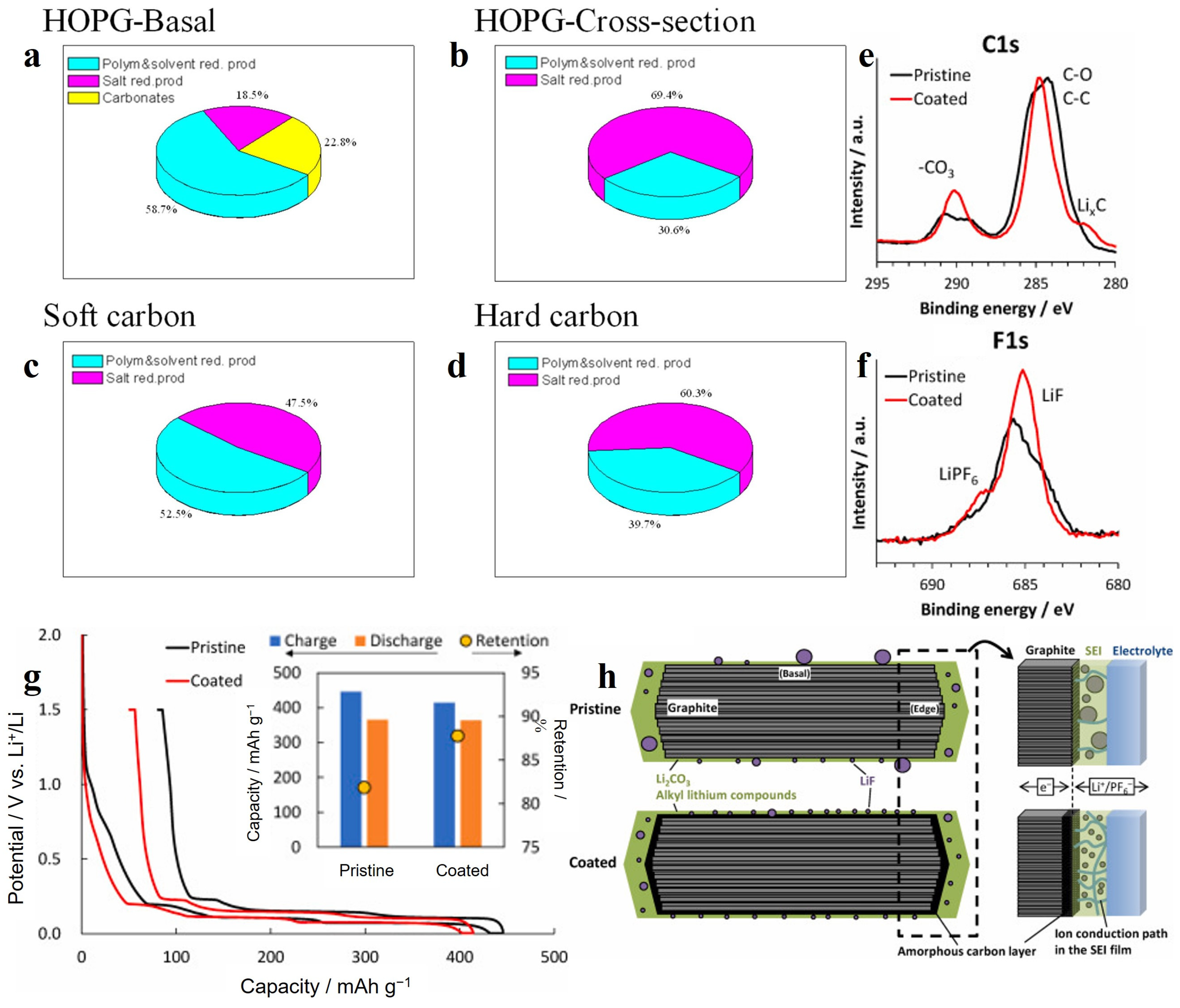
Figure 4.
(a) Charge/discharge profile of the electrode during the initial cycle at 0.2 A g−1, (b,c) ex situ FTIR spectra of electrode at the selected potentials indicated in (a) [73]. Copyright 2017, Wiley-VCH. (d) Galvanostatic charge and discharge profiles of HC and HHC at the first cycle at current density of 100 mA g−1. (e) CV curves of HC and HHC electrode, inset is the magnified image. (f) Proposed mechanism via stabilized solid electrolyte interface between the oxygen functional group and electrolyte [74]. Copyright 2020, Royal Society of Chemistry. (The green and purple circles represent sodium and oxygen atom, respectively. The blue circles represent atoms in SEI. Additionally, electrolyte molecules were illustrated as black hexagonal rings.).
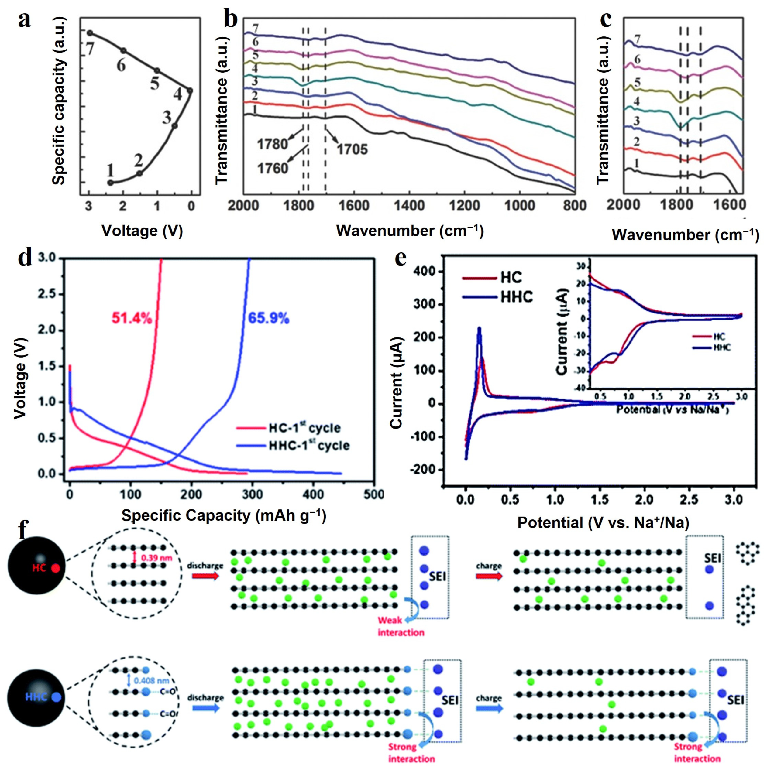
Figure 5.
XPS (a) S 2p and (b) F 1s spectra of PN-CNC at pristine state; high-resolution XPS spectra of (c) S 2p, (d) F 1s, (e) C 1s and (f) K 2p spectra for PN-CNC after discharging to 0.01 V (the cells are cycled at 0.1 A g−1); ex situ XPS (g) P 2p and (h) N 1s spectra of PN-CNC [82]. Copyright 2022, Elsevier. (i) Cyclic performances at 0.5 A g−1 and (j) the corresponding coulombic efficiency plots in different electrolytes of M-NC [83]. Copyright 2022, Wiley-VCH.

Figure 6.
(a) N2 adsorption–desorption isotherms, (b) ID/ID + IG and specific pore volume, (c) XPS C 1s spectra. (d) The first discharge–charge profiles and (e) cycling performance for HC-0.5 electrode at a current rate of 20 mA g−1 in Na half-cell. (f) EIS Nyquist plots after 5 cycles [91]. Copyright 2018, Wiley-VCH.
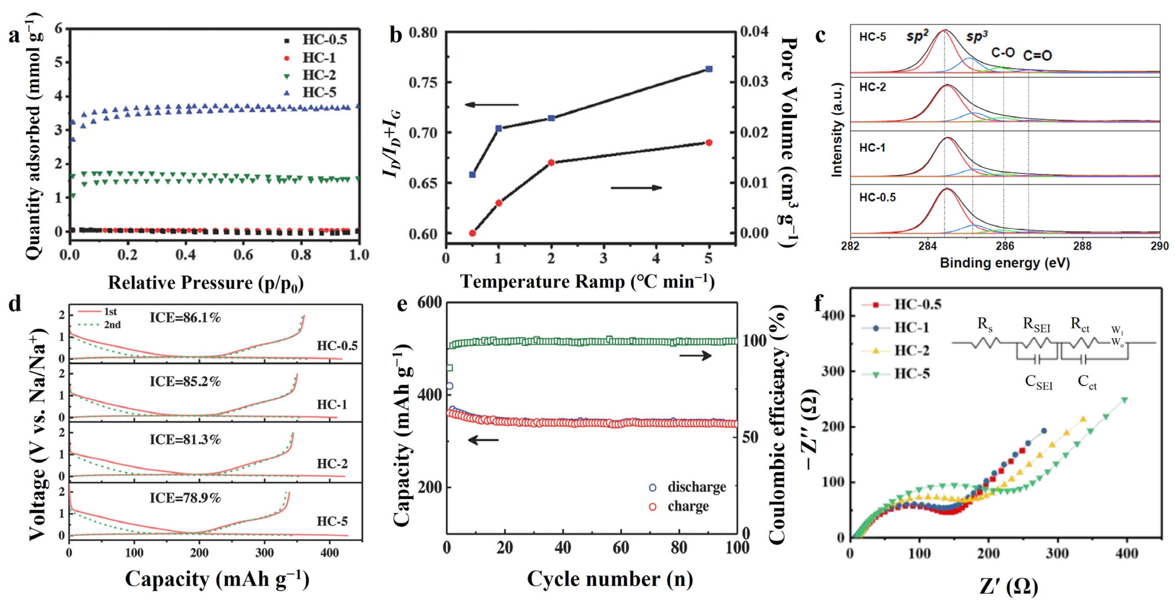
Figure 7.
Schematic illustration of (a) a closed protective cathode electrolyte interphase [98], copyright 2020, Wiley-VCH and (b) formation and confinement of SEI film in porous silicon/carbon composites [101], copyright 2013, Royal Society of Chemistry. (c,d) SEM images of the cross section of a natural graphite sphere; (e,f) the elemental line scan analysis along the black and white lines in panels c and d, respectively [102], copyright 2005, American Chemical Society. (g) Comparison of cyclic performance for the original and coated NG spheres at a 0.2 mA cm−2 and (h) voltage profiles of the original and coated NG spheres, where D1 and C1 represent the first discharge and charge processes, respectively [103], copyright 2006, Elsevier.


Table 1.
Physical parameters for the hard carbon materials [91].
Table 1.
Physical parameters for the hard carbon materials [91].
| Sample | d002 (nm) | La (nm) | Lc (nm) | N | IG/ID | SBET (m2 g−1) | Pore Volume (cm3 g−1) | Pore Size (nm) |
|---|---|---|---|---|---|---|---|---|
| HC-5 | 0.413 | 2.15 | 1.3 | 3.1 | 0.31 | 34 | 0.018 | 2.09 |
| HC-2 | 0.401 | 2.26 | 1.35 | 3.3 | 0.4 | 20 | 0.014 | 1.97 |
| HC-1 | 0.398 | 2.4 | 1.42 | 3.5 | 0.42 | 13 | 0.006 | 1.94 |
| HC-0.5 | 0.391 | 2.53 | 1.46 | 3.3 | 0.52 | 1.74 | - | - |
Disclaimer/Publisher’s Note: The statements, opinions and data contained in all publications are solely those of the individual author(s) and contributor(s) and not of MDPI and/or the editor(s). MDPI and/or the editor(s) disclaim responsibility for any injury to people or property resulting from any ideas, methods, instructions or products referred to in the content. |
© 2023 by the authors. Licensee MDPI, Basel, Switzerland. This article is an open access article distributed under the terms and conditions of the Creative Commons Attribution (CC BY) license (https://creativecommons.org/licenses/by/4.0/).
Share and Cite
MDPI and ACS Style
Zhao, X.; Chen, Y.; Sun, H.; Yuan, T.; Gong, Y.; Liu, X.; Chen, T. Impact of Surface Structure on SEI for Carbon Materials in Alkali Ion Batteries: A Review. Batteries 2023, 9, 226. https://doi.org/10.3390/batteries9040226
AMA Style
Zhao X, Chen Y, Sun H, Yuan T, Gong Y, Liu X, Chen T. Impact of Surface Structure on SEI for Carbon Materials in Alkali Ion Batteries: A Review. Batteries. 2023; 9(4):226. https://doi.org/10.3390/batteries9040226
Chicago/Turabian StyleZhao, Xvtong, Ying Chen, Hao Sun, Tao Yuan, Yinyan Gong, Xinjuan Liu, and Taiqiang Chen. 2023. "Impact of Surface Structure on SEI for Carbon Materials in Alkali Ion Batteries: A Review" Batteries 9, no. 4: 226. https://doi.org/10.3390/batteries9040226
Note that from the first issue of 2016, this journal uses article numbers instead of page numbers. See further details here.