Review

A Tale of Nickel-Iron Batteries: Its Resurgence in the Age of Modern Batteries

by
Justine Marie E. Abarro
1,2,
Jon Nyner L. Gavan
1,2,3,
Daniel Eldrei D. Loresca
1,2,
Maura Andrea A. Ortega
1,2,
Eugene A. Esparcia, Jr.
1 and
Julie Anne D. R. Paraggua
1,2,4,*
1
Laboratory of Electrochemical Engineering (LEE), Department of Chemical Engineering, University of the Philippines Diliman, Quezon City 1101, Philippines
2
DOST-NICER Advanced Batteries Center, University of the Philippines Diliman, Quezon City 1101, Philippines
3
Nanotechnology Research Laboratory, Department of Chemical Engineering, University of the Philippines Diliman, Quezon City 1101, Philippines
4
Energy Engineering Program, National Graduate School of Engineering, College of Engineering, University of the Philippines Diliman, Quezon City 1101, Philippines
*
Author to whom correspondence should be addressed.
Batteries 2023, 9(7), 383; https://doi.org/10.3390/batteries9070383
Submission received: 8 June 2023 / Revised: 6 July 2023 / Accepted: 12 July 2023 / Published: 18 July 2023
(This article belongs to the Special Issue Review of Electrode Materials and Electrolyte for Batteries)

Abstract

:
The nickel-iron (Ni-Fe) battery is a century-old technology that fell out of favor compared to modern batteries such as lead–acid and lithium-ion batteries. However, in the last decade, there has been a resurgence of interest because of its robustness and longevity, making it well-suited for niche applications, such as off-grid energy storage systems. Currently, extensive research is focused on addressing perennial issues such as iron passivation and hydrogen evolution reaction, which limit the battery’s energy density, cyclability, and rate performance. Despite efforts to modify electrode composition and morphology, these issues persist, warranting a deeper look at the development story of Ni-Fe battery improvements. In this review, the fundamental reaction mechanisms are comprehensively examined to understand the cause of persisting issues. The design improvements for both the anode and cathode of Ni-Fe batteries are discussed and summarized to identify the promising approach and provide insights on future research directions.

Graphical Abstract

1. Introduction

Energy storage technologies are crucial to meet electricity demand and mitigate the variability of non-dispatchable resources with the advent of renewable energy. The rising grid-scale battery system offers a faster response time and flexible power to provide ancillary services (i.e., peak shaving and load shifting) [1,2]. High-temperature sodium-sulfur (NaS) batteries and lithium-ion batteries (LIBs) are among the leading chemistries, but they are expensive and face safety issues under high-temperature conditions [3]. The growing demand for batteries also raises scarcity issues concerning the existing world reserves. Olivetti et al. [4] reported that obtaining LIB raw materials is not the primary challenge as several extraction methods are available, but rather the production of battery-grade materials. Iron (Fe) was reported as the most abundant among other common raw materials for batteries, with over 8.8 billion metric tons of world reserves [5]. Nickel (Ni), on the other hand, is a popular raw material with a family of battery chemistries that are commercially successful in medium to large-scale energy storage applications [6]. Among the variations, nickel-cadmium (Ni-Cd) batteries are commercially successful with their long cycle life, high round-trip efficiency, and tolerance to extremely low temperatures [7], yet cadmium toxicity remains a major concern [8]. In contrast, Ni-Fe batteries show comparable performance without substantial health and environmental effects [9,10]. Unlike Ni-Cd batteries, Ni-Fe batteries do not suffer from memory effects and can last up to 25 years without deterioration under overcharged or overdischarged conditions [10]. The advantages enabled them to occupy a niche in the battery market as backup power sources for railway vehicles and off-grid systems, or in applications where high vibration is present. However, two long-standing issues exist—the passivation of the Fe electrode and the inherent hydrogen gas evolution during charging. Because of these, lead–acid batteries have superseded Ni-Fe batteries due to the former’s cheaper operating and maintenance costs, and LIBs have become popular with their high capacity (Figure 1) [11,12,13]. Commercial lead acid batteries and LIBs have a specific energy of 30–35 Wh kg−1 and 150 Wh kg−1 [14] which significantly outperforms commercial Ni-Fe batteries having only around 19–55 Wh kg−1 [15]. Despite these limitations, there is a renewed interest in Ni-Fe batteries, primarily driven by the clean and low-cost materials, longevity, and tolerance to electrical abuse [16,17,18]. Eliminating the drawbacks is challenging, but improvements using nanomaterials are gaining traction after achieving ultrafast charge and discharge rates by nearly a thousand-fold compared to commercial counterparts [16]. The work of Hongjie Dai’s group [16] in 2012 was a catalyst for further improvements, which focused on understanding electrode performance [19,20], incorporating carbon on electrodes [21,22], and exploring additives [23,24]. Recent studies are also considering practical fabrication techniques that account for production costs. For instance, many studies [25,26,27,28,29,30,31] have leaned towards nanotechnology to enhance battery performance, but this approach often requires costly methods and reagents to produce nanomaterials. This can be at odds with the goal of using low-cost and widely available raw materials. Most reported results were also tested at low current densities, which do not accurately reflect practical applications.
This review begins with a brief discussion of the fundamental reaction mechanisms in a Ni-Fe battery to understand how to mitigate passivation and hydrogen evolution. Thomas Edison’s Ni-Fe battery, with Fe metal negative plates and NiOOH positive plates, was reported to have a specific energy of 30 Wh kg−1, which is far from the theoretical value of 314 Wh kg−1 [14]. The discrepancy between the theoretical and practical values urges further research on battery design improvements. Several approaches have been employed to overcome these issues and enhance the performance of the different battery components (Figure 2). These include modifying the morphology to create unique architectures, introducing defects, and producing composites and core–shell structures for both electrodes. Incorporating bismuth (Bi) and sulfide additives into the anodes, stabilizing the α-Ni(OH)2 cathodes, and using organic and inorganic electrolyte additives are also gaining attention. Existing review articles discuss the recent progress of different iron-based anodes [32,33,34] and nickel-based cathodes [35] for aqueous-based batteries. In this review, advancements for both the anode and cathode within the context of Ni-Fe batteries are examined. The current optimization strategies and their reported performance are summarized and discussed to identify the research trajectory and offer valuable insights into the key developments in this field. Moreover, the performance of the optimized full cell could expand the areas of application. For instance, while commercial Ni-Fe batteries have proven their practicality in stationary and/or large-scale applications, recent research proved their feasibility in flexible assemblies and as hybrid battolysers. Lastly, this review concludes with perspectives and recommendations to consider other feasible techniques in developing advanced Ni-Fe batteries.

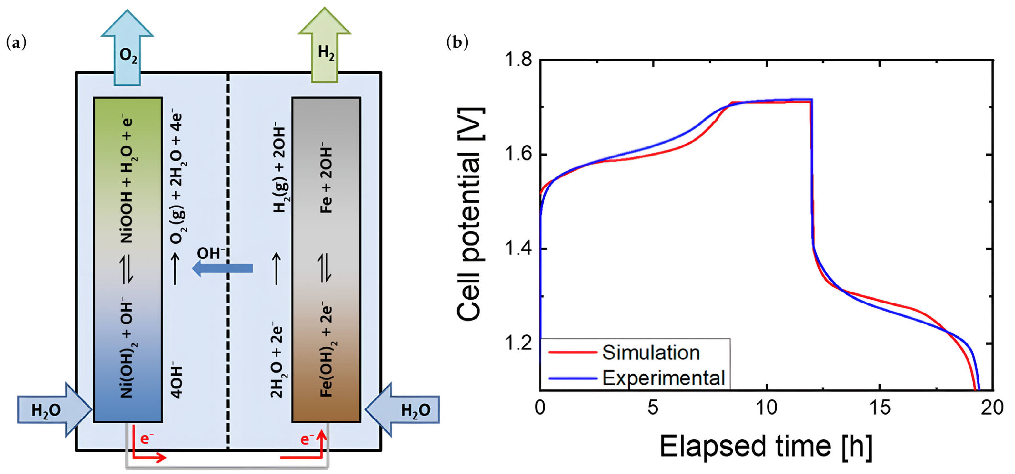
2. Nickel-Iron Battery Chemistry

Commercial Ni-Fe batteries are typically made of a metallic Fe negative electrode and a nickel oxyhydroxide (NiOOH) positive electrode submerged in an electrolyte containing 25–30% potassium hydroxide (KOH) solution and ~50 g/L of lithium hydroxide (LiOH) additive [15]. The overall reaction is quite complex as it involves intermediate species that result in different possible products. During the charge–discharge process, the electrolyte’s role is not apparent in the overall reaction, as shown in the following reactions:
First Plateau:
F e + 2 N i O O H + H 2 O 2 N i O H 2 + F e O H 2
Second Plateau:
3 F e O H 2 + 2 N i O O H 2 N i O H 2 + F e 3 O 4 + 2 H 2 O
Overall Reaction:
3 F e + 8 N i O O H + 4 H 2 O 8 N i O H 2 + F e 3 O 4
The electrolyte, however, takes part in reactions at the individual electrodes. With the reactions involved, a Ni-Fe battery can provide an open circuit voltage of ~1.4 V and a nominal voltage of 1.2 V, which is lower compared to lead–acid batteries (2.0–2.2 V) and LIBs (2.5–4.2 V) [15]. To significantly improve Ni-Fe battery performance, it is crucial to understand the fundamental and competing reactions involved. The succeeding section, thus, discusses the different reactions and issues encountered during operation, and the possible solutions to enhance its performance further [15]. To significantly improve Ni-Fe battery performance, it is crucial to understand the fundamental and competing reactions involved. The succeeding section, thus, discusses the different reactions and issues encountered during operation, and the possible solutions to further enhance its performance.

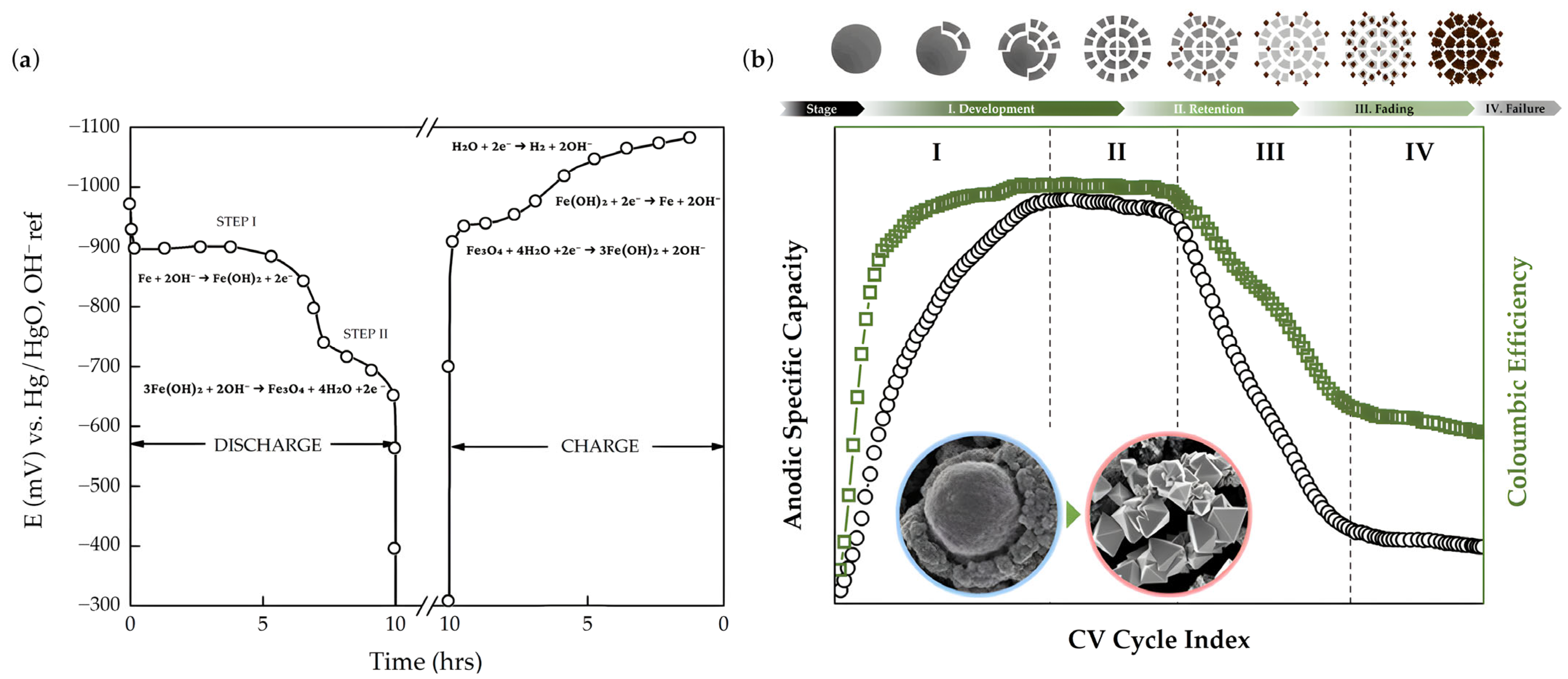
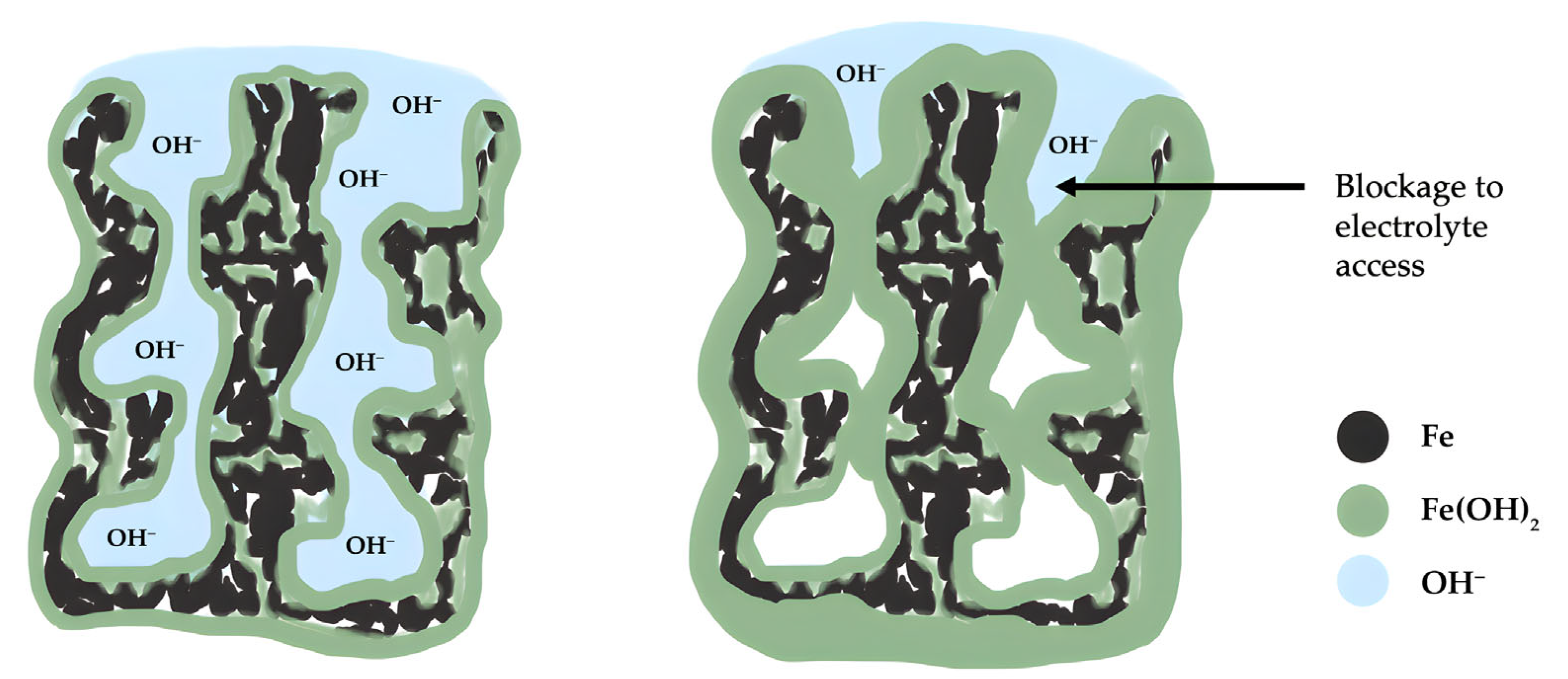
2.1. Negative Electrode

Metallic Fe undergoes a series of chemical reactions during battery operation. Due to its thermodynamically unstable nature in water, it inherently corrodes in aqueous solutions. During discharge, Fe interacts with OH ions in the electrolyte to form iron (II) hydroxide [Fe(OH)2]:
F e + 2 O H F e O H 2 + 2 e   E ° = 0.88   V   v s .   S H E
The Fe anode oxidation process is governed by dissolution-precipitation, where Equation (4) can be divided into two reactions that lead to the formation of a slightly soluble intermediate HFeO2 (Equation (5)).
F e + 3 O H H f e O 2 + H 2 O + 2 e
H f e O 2 + H 2 O F e O H 2 + O H
The surface of the electrode becomes supersaturated with HFeO2, which is then hydrolyzed and reprecipitated to form a dense anodic film of Fe(OH)2 adjacent to the metal (Equation (6)) [37,38]. Complicated reactions may arise when Fe(OH)2 reacts with the OH ions in different ways, creating a variety of oxides with poor conductivity [23,39,40].
F e O H 2 + O H F e O O H + H 2 O + e     E ° = 0.56   V   v s . S H E
3 F e O H 2 + 2 O H F e 3 O 4 + 4 H 2 O + 2 e   E ° = 0.66   V   v s .   S H E
2 F e 3 O 4 + 2 O H 3 F e 2 O 3 + H 2 O + 2 e E ° = 0.60   V   v s .   S H E
Each reaction is represented by different voltage plateaus in a charge–discharge curve (Figure 3a) [41]. The initial discharge step demonstrates a theoretical capacity as high as 960 mAh g−1. In practical applications, however, the capacity may only reach ~150–550 mAh g−1, depending on the Fe electrode used [41]. After a few cycles, the capacity usually stabilizes in a process called ‘electrode formation’. The produced oxides form a passivation layer that hinders electrolyte interaction with the active material. While the three reactions (Equations (7)–(9)) may happen simultaneously, certain conditions will dictate which reaction will proceed [32,39]. For instance, Fe(OH)2 does not completely convert to oxides during cycling because of its low conductivity [27]. While in some cases, the anodic dissolution of the Fe electrode at elevated temperatures (35–55 °C) results in direct electrochemical conversion of Fe to Fe3O4 (magnetite) [42]. The discharge rate plays a critical role in product formation. Low discharge rates heighten electrode corrosion, while higher rates encourage passivation [20,41]. As both cases lead to poor electrode capacity, different parameters (e.g., electrode morphology, electrolyte concentration, etc.) may be optimized to achieve a desirable performance at high discharge rates [43].
According to Lee and co-workers [39], the Fe electrode transformation during cycling can be divided into four stages: development, retention, fading, and failure (Figure 3b). Fe particle fragmentation initially occurs by increasing the electrode surface area, enhancing discharge capacity (Stages I–II). After multiple cycles, irreversible maghemite (γ-Fe2O3) forms, causing a gradual capacity decrease until it reaches failure due to aggregation (Stages III–IV) [39]. During charging, hydrogen evolution reaction (HER) occurs inevitably at a slightly less negative electrode potential compared to the Fe(OH)2 reduction (Equation (4)).
2 H 2 O + 2 e H 2 + 2 O H   E ° = 0.83   V   v s .   S H E
A portion of the energy used during charging is given to the parasitic HER, resulting in a low charging efficiency of the full cell. The Fe electrode also corrodes in the charged state intensifying its self-discharge rate. Most anode improvements focus on HER suppression by introducing Bi-based additives to increase HER overpotential [44,45], and/or the design of Fe electrodes (e.g., sintered, hot-pressed, etc.) [46,47]. Some studies have also introduced unique concepts, such as HER inhibitors that adsorb on electrode surfaces, reducing active sites for water electrolysis, and anticatalysts that bind with HER intermediates to facilitate energy storage charge carriers to occupy active sites [48,49].

2.2. Positive Electrode

Nickel hydroxide [Ni(OH)2] is the conventional cathode material for Ni-Fe batteries because of its high specific capacitance and low material cost [35,50]. The main reaction of this cathode material is shown as follows:
N i ( O H ) 2 + O H N i O O H + H 2 O + e   E ° = 0.52   V   v s .   S H E
In contrast to the iron anode, which faces the inevitable occurrence of HER during charging, the latter’s counterpart half reaction in water splitting, the oxygen evolution reaction (OER) is not a major concern at the nickel cathode. First, the onset of OER in alkaline media occurs well after the Ni(II)/Ni(III) redox wave (Equation (11)) [51]. Second, OER includes four proton-coupled electron transfer and O-O bond formation—processes that are kinetically unfavored and require catalysts to proceed [52]. Studies have reported that nickel and its oxides exhibit some ability to lower the OER overpotential, indicating their potential as OER electrocatalysts [53]. However, pure Ni/NiOx is not enough to drive OER in alkaline systems. Research on Ni-based OER electrocatalysts report that the presence of other atoms such as Fe in nickel layered hydroxides is essential to effectively allow OER to proceed [54]. Moreover, the Fe atoms act as active sites for OER instead of Ni. Research shows that in Fe-free Ni(OH)2 electrodes, OER occurs at potentials at least 200 mV more positive compared to Fe-containing Ni(OH)2 [54,55].
The Ni(OH)2 has two naturally occurring crystalline polymorphs—the hydrotalcite-like α-phase and the brucite-like β-phase (Figure 4).
The α-phase is composed of positively charged Ni(OH)2 layers where water molecules and anions (typically counter-ions of Ni salts used for electrode synthesis) intercalate [18,35]. When charging, the α-Ni(OH)2 undergoes a transformation to γ-NiOOH with little volume change due to their similar structure and interstitial spacing (~7 Å) [57]. This α↔γ transformation yields a high electron transfer of ~1.67 [58], which contributes to the high theoretical energy density of α-Ni(OH)2 of around 482 mAh g−1 [35]. While this is an impressive feat, the α-Ni(OH)2 is less preferred as cathode material due to its instability in an alkaline media. When the α-phase converts to β-Ni(OH)2 via dehydration [59], the interstitial spaces reduce by 40%, which leads to capacity fading. In some cases, when electrodes are left uncycled, the incomplete conversion of γ-NiOOH during discharge may arise [60]. The α-Ni(OH)2 layer forming on the electrode surface exhibits an insulating behavior. The β-Ni(OH)2, on the other hand, is thermodynamically stable in alkaline solutions, but offers a much lower theoretical capacity of 289 mAh g−1, with practical capacities ranging from 237 to 263 mAh g−1 [61]. This is because the transformation to β-NiOOH only involves a single electron transfer. When overcharged, the β-NiOOH may also undergo further oxidation to form γ-NiOOH. As a result, the large volumetric difference (~33% change) between β/γ-NiOOH compromises the cathode’s structural stability.
Combining all these problems for both phases leads to insufficient material utilization of Ni(OH)2, limited energy density, unfavored reversibility, and poor rate performance [35,50]. Thus, research on improving the Ni(OH)2 positive electrode performance mainly focuses on improving the intrinsic conductivity of the electrode [62,63,64,65,66,67,68], enhancing the electrochemically active area [68,69,70,71], and improving the structural stability [58,72,73,74,75].

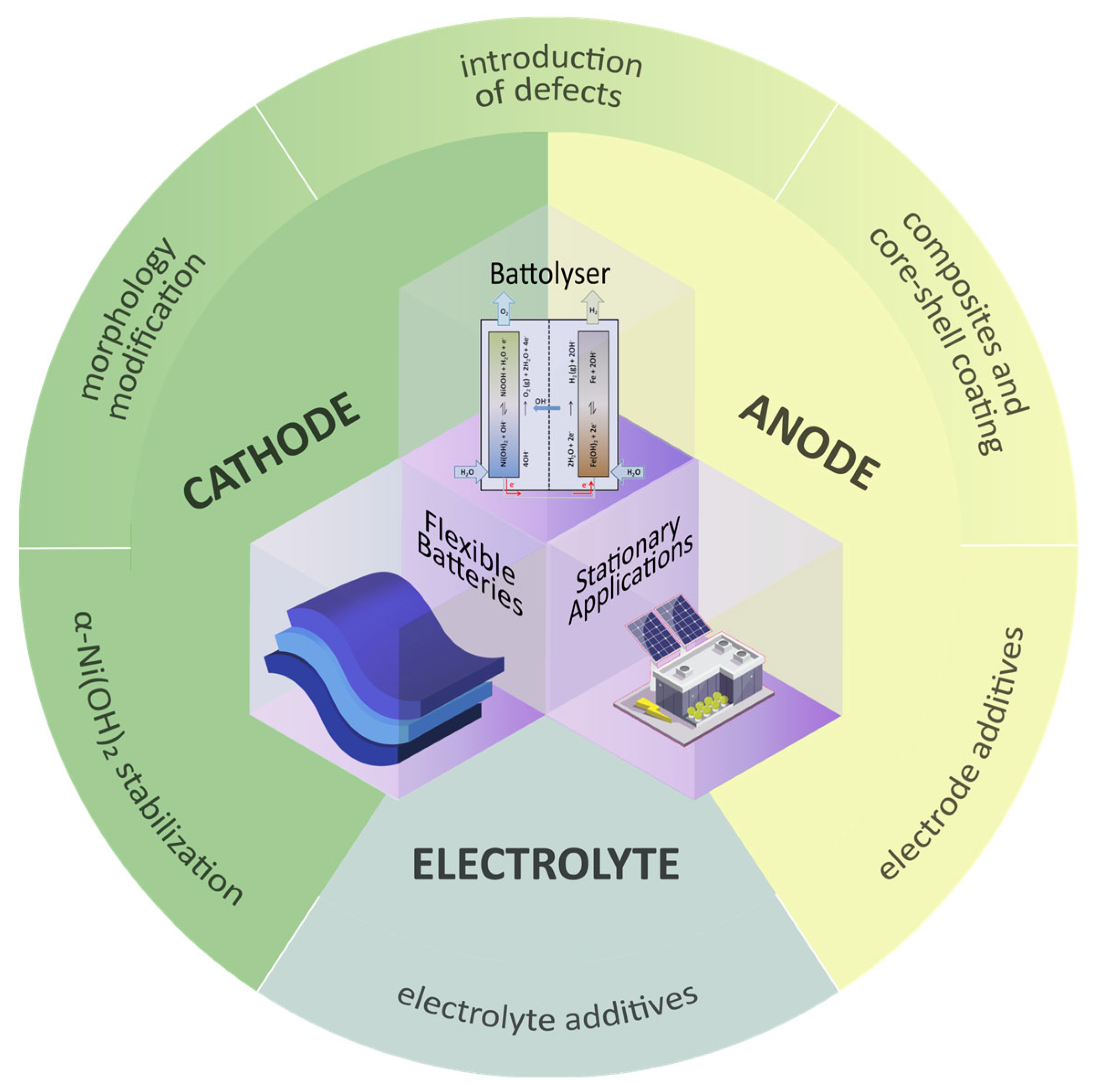
3. Negative Half-Cell Design Improvements

The majority of improvements in Ni-Fe batteries have focused on negative half-cells because of Fe passivation at high discharge rates and hydrogen formation during charging. Passivation, in which nonreducible oxide films accumulate on the Fe-based electrode surface (Figure 5), lowers the electrocatalytic activity by limiting the diffusion of OH anions to the free anodic active sites [75]. As the layer thickens, the interior becomes increasingly inaccessible to the electrolyte and the active material remains unutilized. This highlights the importance of material morphology, which can be fine-tuned through ingenious methods to create unique architectures.
The active material can also be modified by introducing defects through a wide range of techniques including direct growth of oxygen-deficient Fe-based nanoparticles, template etching, and heteroatom doping of high-valence metal ion dopants, multi-cation dopants, or rare earth dopants, as discussed in Section 3.2. Moreover, to further improve the electronic properties of the Fe electrode, various configurations (i.e., metal-core/Fe-shell, Fe-core/metal-shell, carbon-core/Fe-shell, Fe and metal co-precipitate) can be considered to form Fe-based composites. Section 3.3 compared these different composites and elucidated the best-performing configuration.
Hydrogen formation, on the other hand, is an unwanted reaction that causes lower coulombic efficiency as the battery loses capacity when cycled further [21,40]. Simultaneously, this makes Fe-based aqueous batteries high-maintenance with the constant replenishing of electrolytes due to water loss. Two ways to mitigate this parasitic reaction are introducing electrode or electrolyte additives. The subsequent discussion on improvements for the negative half-cell is categorized according to modifications on the electrode design, and the electrolyte composition.

3.1. Material Morphology

Apart from electrochemical affinity, the electrode’s morphology can strongly influence the battery’s performance. For instance, the size and spherical structure of metallic Fe particles may affect their susceptibility to corrosion and the degree of aggregation. Fe particles experience multiple valence states upon oxidation, which raised interest in exploring nanostructured Fe oxides (i.e., α-Fe2O3, γ-Fe2O3, Fe3O4, etc.) having higher oxidation states [29,76,77]. Fe oxides are more stable anode materials in alkaline solutions than pure metallic Fe due to the high degree of symmetry of Fe atoms in the crystal lattice. However, they have relatively low electronic conductivity due to the significant number of oxygen ions acting as electron acceptors. Several strategies to ameliorate the aforementioned electronic conductivity issue are undertaken to optimize the Fe-based electrode morphology, including material functionalization, the improvement of material preparation, and the control of synthesis parameters, as reported in Table 1.
Drawing inspiration from nature, some notable studies explored the concept of biomimicry to develop functional materials. Lai and co-workers [65] created a synergistic vines-grapes-like Fe3O4-N-rGO-CNT>N-PEGm (collectively referred to as Fe3O4-NGC) composite (Figure 6a) through hydrothermal synthesis, which exhibited a capacity of 308 mAh g−1 at 1 A g−1. Each component in the ternary composite plays a distinct and crucial role. The carbon nanotube (CNT) facilitates ballistic electron transport, thereby increasing the overall conductivity of the electrode. CNTs, however, agglomerate within the matrix structure because of their high affinity under the action of van der Waals forces [116]. The grapes-like Fe3O4 nanoparticles and leaf-like Fe3O4 nanosheets serve as the active materials that prevent the restacking of N-GO nanosheets during GO reduction. At the same time, the N-GO mitigates Fe3O4 nanoparticles/nanosheet aggregation. The PEGm (methoxypolyethylene glycol) functional group also helps suppress particle aggregation through surface functionalization by making the electrode surface receptive to ion binding.
In another biomimetic approach, Zhang et al. [78] introduced a phase-transition strategy to produce highly puffed Fe⊂carbon nanopopcorns from compact spherical Fe2O3 nanoparticles coated with thick polydopamine layers (Figure 6b). Phase transition was triggered through instantaneous puffing at 600–800 °C, which involves tight particle compression and rapid pressure release. The loosened permeable carbon matrix provides transport channels for ion diffusion while being mechanically stable enough to accommodate Fe volume expansion. Due to the enlarged specific surface area, a fast redox reaction and a maximum discharge capacity of 480.5 mAh g−1 at 1 A g−1 were observed. Even at a high discharge current of 20 A g−1, it maintained a specific capacity of ~300 mAh g−1 (~62.5% of maximum capacity). When paired with NiO@C, the full cell experienced negligible capacity fading with 95.5% retention after 4000 cycles. However, the high-temperature annealing process to induce the Fe3+/Fe0 phase transition challenges the commercialization of the Fe nanohybrid in terms of cost, safety, and scalability.
Bimetallic textures involving sacrificial zinc templates are a simple and effective approach to creating dendritic or porous structures. Huang et al. [79] electrodeposited bimetallic MZn (M = Ni, Fe) on a copper substrate current collector and removed the zinc scaffolds through cyclic voltammetry (CV) activation to configure the structure further. The FeOx nanowire electrode resulted in a maximum areal capacity of 0.32 mAh cm−2 at 20 mA cm−2. At a five-fold higher current density, it delivered a rate capability of 0.23 mAh cm−2, which is 72% of the recorded maximum capacity. It also showed poor capacity retention of only 75% after 1000 cycles. Zhang et al. [30] produced mesoporous Fe3O4@C nanoarrays through a different technique using calcination followed by alkaline etching of zinc templates. At 5 A cm−2 current density, the recorded maximum capacity was ~0.526 mAh cm−2 and maintained a rate capability of ~0.342 mAh cm−2 (65% of the maximum capacity) when discharged at a current five times higher. Notably, the cycling of the nanoarrays remained high, with 90.8% retention after 5000 cycles. The poor rate capability can be explained by certain caveats which may arise when using self-generated sacrificial templates, including the incomplete removal of zinc, the limited control over pore size distribution causing the non-homogeneous distribution of active species, and the possible detachment of active material from the substrate. Increasing the zinc proportion may also affect the surface area, leaving more cavities and leading to structural collapse from the constant OH insertion [30].
Other than the influence of material and method on morphology, process optimization directly affects the material dimensionality. Song et al. [80] elucidated how Fe2+ source concentration promotes the transition from zero-dimensional particles to one-dimensional (1D) growth of FeOOH nanorods. Excess Fe ions supersaturate the graphite surface to form abundant nucleation sites, encouraging rod-like structures’ epitaxial growth. The density of the rods can be controlled by varying the concentration of the Fe2+ source. In contrast, lower concentrations result in dispersed particles with no preferential growth direction. The annealing temperature is another key factor that influences dimensionality. For instance, the subsequent annealing of the amorphous FeOOH nanorods at 400 °C results in a 3D interconnected network of α-Fe2O3, suggesting that the annealing process promotes oxyhydroxide dehydration. Increasing the annealing temperature was also found to improve the capacity by ~25%, from 147 mAh g−1 at 2 A g−1 when the annealing temperature was 400 °C to 183 mAh g−1 when the temperature was increased to 550 °C.
Conventional Fe anodes in commercial Ni-Fe batteries are typically available in pressed or sintered forms with a dense and uniform structure [15,38]. Narayanan’s team has reported notable improvements in sintered and pressed-plate electrodes over the years [20,23,46]. Sintered Fe electrodes appear to have a highly porous interconnected disc-shaped network [46] (Figure 6c). After discharge, the overall electrode structure remains porous, but the particle shape transforms into an irregular polyhedron. In contrast, pressed-plate carbonyl Fe electrodes are denser and less porous (Figure 6d). During the formation period, where initial charge–discharge cycles are performed, Weinrich et al. [117] observed that the surface particles considerably coarsened, resulting in an increased active surface area, which supports Manohar et al.’s [20] study. Depending on the composition and formation condition, pressed-plate Fe electrodes require five times the number of cycles as sintered Fe electrodes for a sufficient formation, rendering them less cost-effective [118]. By understanding the effect of composition and method on morphology, it is possible to tailor material properties to meet the desired performance.

3.2. Introduction of Defects

Defect engineering is another way of enhancing the electronic characteristics of a material by manipulating defects through vacancies, interstitials, dislocations, and/or impurities. Heteroatom doping can be used to create cation or anion vacancies either on the carbon substrate or active material [119,120,121]. Inducing cation vacancies is usually preferred due to the cation’s smaller ionic radius, which minimizes irregularity in the periodicity of the crystal lattice. Nitrogen, an effective dopant in carbon-based materials because of its high electronegativity, attracts nearby carbon atoms to form a polarized C-N bond [122]. This bond increases the electron density of the material, improving the electronic conductivity. N-doping also stabilizes carbon materials without the need for auxiliary additives such as pore-formers, conductive agents, or binders [123,124,125,126].
Presently, there are limited studies on Fe-based anodes with N-doped carbon substrate for Ni-Fe batteries, as most studies are intended for LIBs. For instance, Li et al. [123] developed an N-doped carbon nanofiber (NCFM) substrate for CoFe2O4 (CFO) nanoparticles where nitrogen can form strong bonds with CFO to mitigate agglomeration. Alternatively, some studies encapsulated Fe particles with an N-doped carbon-shell to prevent contact of particles from each other [124,125,127]. Liu et al. [126] induced metal-rich cation vacancies on Fe-based materials integrated into carbon hybrids (FexC@NC) through SiO2 template etching. The induced Fe vacancies in Fe3C resulted in hierarchical pores and exposed active sites for electrolyte penetration. Nonetheless, some studies suggest that N-doping can enhance HER activity under alkaline conditions as the polarized bond attracts H+ species [81,82]. This is in conflict with the objective of suppressing HER in Fe-based anodes. In contrast, dopants such as sulfur can increase the charge and spin density of Fe-based anodes to enhance oxygen reduction reaction (ORR) activity while limiting HER [128].
Aside from nitrogen, high-valence metal ion (HVMs) dopants can further modify the crystal and electronic structure of the material. HVMs have more available electrons for chemical bonding that initiate stronger interactions within the lattice structure of an Fe-based anode to change its electronic state significantly [129]. Wang et al. [130] incorporated Ti4+, Sn4+, and Zr4+ HVMs on ultrasmall Fe2O3 on CNT support (HVM-FeO–CNT) through a repeated dip-and-burn process to produce supercapacitors. Li et al. [131] reported a two-step mechanism of substitutional and gap doping of cobalt on α-Fe2O3 nanoparticles to reduce the wide band gap of the metal oxide. Dopant concentrations largely influence the particle size distribution and the degree of crystal lattice distortion of α-Fe2O3. High cobalt-doping concentration refines the average grain size of Fe2O3 as Co2+ accumulates at the grain boundaries, providing more electroactive sites. Moreover, the interlayer spacing expands to accommodate ion transport as cobalt inserts in the crystal lattice. In contrast, low-valent doping using Li dopants favors photoelectrochemical water oxidation as Li atoms occupy the α-Fe2O3 interstitial sites and reduce the oxygen vacancies [132].
Qiu et al. [77] conducted direct growth of oxygen-deficient α-Fe2O3 nanorods on 3D carbon cloth to produce CC@α-Fe2O3 through a facile hydrothermal process. The resulting electrode displayed a discharge capacity of 308.9 mAh g−1 at 1 A g−1 and a good rate capability of 81% after achieving 250.6 mAh g−1 at a current density as high as 40 A g−1. Such performance can be attributed to the introduction of oxygen vacancies that induced highly porous surfaces without compromising structural stability.
While many doping strategies are surficial, Chen et al. [133] demonstrated the synergistic effect of surface phosphorylation and bulk phosphorus doping on Fe2O3 nanoporous arrays for LIB applications. Surface doping suppressed surface side reactions and promoted selectivity towards anodic oxidation, while bulk doping enhanced the ion and electron transport and the surface faradaic redox sites. To maximize the advantages of doping, Liu et al. [134] demonstrated a dual P doping strategy that induces defects on both the Fe3Se4 anode and graphene carbon substrate. P-doped graphene confining the P-doped Fe3Se4 mitigates the volume variation during cycling and enhances surface conductivity. While extensive studies on single-cation doping introduced advantages in material properties, multi-cation doping offers a more precise tuning of material properties. It synergistically enhances the desired properties of the material [135,136]. Ouyang et al. [136] performed multi-cation doping of Ni, Co, and Yb cations on β-FeOOH nanorods, with each cation serving a specific function. The Ni and Co ions, having similar ionic radii with Fe ions, replace Fe3+ and Fe2+ to produce oxygen vacancies. Likewise, rare earth dopants such as Yb3+ promote rich oxygen vacancies and modulate the electronic and lattice structure of the material. The Yb3+ entering the interstitial sites enrich edge dislocations as active sites for oxygen evolution. However, if the dopant concentration of Yb3+ is excessive, it may inhibit the function of the transition metal cations, highlighting the importance of optimizing the concentration of each cation.

3.3. Material Composites

Achieving an ideal combination of reinforcement and matrix materials has drawn a lot of interest in improving the performance of Fe electrodes. Various reinforcement materials have been explored, including transition metals [97,109], metal oxides [48,86,112], intermetallic compounds [48], and carbon. Transition metals (TM) and their oxides are known for their high theoretical capacity, ideally making them good reinforcements for Fe-based composites. For instance, Huang et al. [96] synthesized a Cu/Fe composite through a one-step co-precipitation method followed by calcination at 800 °C. It achieved a capacity of 230 mAh g−1 at a 1C rate after the 50th cycle and still maintained 56.5% capacity even at a ten-fold increased discharge rate. Copper is a conductive nucleation site for the Fe dissolution–deposition process, explaining the good capacity retention.
Composites can be configured in different ways, viz: (1) TM-core/Fe-shell, (2) Fe-core/TM-shell, and (3) uniform mixture of Fe and TM via co-precipitation. Kao et al. [109] observed that the Cu-core in Fe-shell aggregates resulted in a rapid capacity decay. At the same time, co-precipitation did not promote a good connection between the metal particles. The Fe-core/Cu-shell configuration, on the other hand, had the best capacity retention. The nanosized Fe/Cu (weight ratio 2:1) composite produced via NaBH4 chemical reduction demonstrated the most stable discharge curves at the initial cycle (Figure 7a). Moreover, it achieved a total discharge capacity of 1443 mAh g−1 at a constant current of 0.2 A g−1 during the first run. Upon further cycling, the total discharge capacity dropped quickly to 800 mAh g−1 at the same current density (Figure 7b). Traces of unconverted Fe3O4 indicate that the inevitable loss of some Fe material likely causes capacity fading. Nonetheless, it exhibited a good rate capability after maintaining discharge capacity even at a high current density 3.2 A g−1 after 16 cycles.
Further exploring variations of transition metals, Comisso et al. [48] fabricated Fe composites with metal oxides (Al2O3, ZrO2, ZnO, TiO2) and intermetallic compounds (LaNi5, TiNi) through milling. Most oxide composites have low charge-storage capability due to the strong interaction of oxides with Fe, which partially shields it from the electrolyte and inhibits Fe oxidation. While some intermetallic compounds (IMCs) such as TiNi can increase the hydrogen overpotential, not all IMCs have good compatibility with Fe. For instance, Fe/LaNi5 demonstrates total incompatibility between the redox systems of the two constituents as LaNi5 acts both as a catalyst for HER and a hydrogen absorber.
With Fe’s propensity to undergo multivalent oxidation, several studies attempted to pair Fe with its oxides to address issues on volume changes and cycling stability caused by the existence of different valence states. Zhu et al. [112] electrodeposited and then thermally annealed a rock-like Fe/Fe3O4 on carbon fiber to produce a stable mesoporous microstructure. The resulting material had a capacity of 160 mAh g−1 at 3.43 A g−1 and maintained a rate capability of 90.32 mAh g−1 after being discharged three times its initial capacity. In another study, Zeng et al. [86] produced a quaternary carbon/Fe/FeO/Fe3O4 (CFFF) from a one-step in situ solid-state reaction. The composite exhibited 604 mAh g−1 at 1 A g−1 and retained 257 mAh g−1 under a fifty-fold increase in current density. Both studies agree that the annealing temperature (500–700 °C) is pivotal to producing a stable lattice structure that can withstand high current densities without deterioration.
Carbon, with its good structural tunability, superior electronic conductivity, and excellent chemical stability, has become a popular reinforcement for composite electrodes [137,138]. Among the variety of carbon materials explored are graphene [16,92,93,106], carbon blacks [107], and CNTs [29,88,95]. Functionalization of the carbon substrate is vital to create nucleation sites for the growth of Fe-based crystals. This is achieved by incorporating hydrophilic substituents, such as hydroxyl, carboxyl, and carbonyl groups, onto the surface or edge of the carbon material. In turn, an increase in the dispersibility of the carbon material in aqueous media can be achieved [139,140,141]. Moreover, the oxygen-containing groups ensure strong coupling between the carbon material and Fe-based nanoparticles [16]. In a comparative study, Arunkumar et al. [108] cited that Fe2O3 on multi-walled carbon nanotubes (MWCNTs) exhibited sharp redox peaks, outperforming other carbon materials. With their large surface area, the porous MWCNTs enabled Fe particles to infiltrate and improve contact with carbon. Various organic compounds can be used as carbon sources, but glucose and sucrose are often used due to their low cost. In addition, Hang and co-workers [26] also determined the C:Fe ratio as a factor that affects the redox behavior of the negative electrode, recommending a higher C:Fe weight ratio (≥8:1) to achieve a stable discharge capacity. Intuitively, a large amount of Fe2O3 loaded on carbon leads to a rapid decrease in discharge current due to the formation of a thicker Fe(OH)2 layer.
There are a few ways to incorporate carbon with Fe electrodes: depositing or growing Fe nanoparticles on a carbon-based substrate and/or by coating carbon on Fe. According to Wang et al. [16], growing Fe particles on reduced graphene oxide (FeOx/rGO) mitigates passivation and shows good rate capability. Initially, a high capacity was recorded at 300 mAh g−1 due to the high active surface area, but it quickly decays to 200 mAh g−1 after 200 cycles. This rapid deterioration is caused by weak Fe-C coupling and Fe agglomeration. When carbon coating was introduced over the FeOx nanoparticle, capacity retention improved by ~22%, maintaining a capacity of 240 mAh g−1 at 300 cycles. Wang et al.’s [16] study paved the way for many succeeding studies to adopt the carbon coating technique. To ensure a uniform and complete coverage of Fe particles, several studies considered a carbon-shell approach to mitigate the volume changes of Fe further. Shell thickness is a crucial factor that influences electrode cyclability and capacity. A layer that is too thin may not be enough to restrict the volume expansion, while a thick coating hinders ion diffusion [22,27,76]. A carbon-shell thickness of ~20–35 nm has been observed to provide sufficient capacity and stability. [78,94,99,102].
In one practical study, Zhang et al. [94] developed Fe@C nanoparticles from plastic and rusty waste via a one-step chemical vapor deposition. This electrode composite achieved a capacity of 405.2 mAh g−1 at 1A g−1 and a ∼91.9% capacity retention after 4000 cycles, citing that the Fe nanoparticles are readily activated while tightly enclosed in a carbon-shell. However, when paired with a NiO@C cathode, the full cell assembly shows a discharge capacity of 138.9 mAh g−1 at 1 A g−1 and only retains 53% of the capacity (74 mAh g−1) at 8 A g−1. This poor rate capability is caused by the carbon-shell restraining the Fe reaction kinetics. Moreover, despite the widespread use of the carbon-shell technique, many studies have demonstrated substandard performance, often due to significant capacity fading after only a few hundred cycles [21,76,84,103].
As a solution, Li et al. [102] introduced self-adapting carbon-shell nanoreactors on metallic Fe nanoparticles (Fe@TCNRs) via in situ gas phase evolution, which resulted in a capacity of 491 mAh g−1 at 1 A g−1, and a capacity retention of ~90% after 4000 cycles. The self-adapting carbon-shell, with a reduced thickness of ~3–4 nm, accommodates volume changes by exploiting the weak interactions between graphitic stacking layers (Figure 8). Other coating materials may also be viable alternatives, as demonstrated by Liu et al. [29] after coating the surface of α-Fe2O3 nanorods on CNT fibers. Fe-based particles grown on the surface of carbon materials allow for strong covalent coupling between the two materials, resulting in a rapid electron transfer from active materials to current collectors with polypyrrole (α-Fe2O3@PPy NRs/CNTF).
The presence of PPy resulted in a capacity as high as ~620 mAh g−1 compared to ~400 mAh g−1, where no coating was applied. Nickel sulfides were also reported to improve Fe discharge capacity significantly [67,100,101]. The Ni2+ ions possibly formed Ni(OH)2 during cycling, which retards the formation of the Fe(OH)2 passivation layer leading to structural deformation [100]. Additionally, a high specific capacity of 481.2 mAh g−1 at 1.2 A g−1 was reported. Like carbon-shell coating, other materials mentioned displayed low-capacity retention after 100 cycles. This may be caused by the coating material influencing the capacity of the composite during the charge and discharge process.
Transition metal dichalcogenide (TMDs), with a chemical formula of MX2 (M = transition metal; X = chalcogen), have good mechanical and corrosion stability in electrochemical conditions due to the strong covalent bonds between layers, making them suitable materials for aqueous batteries [142]. Moreover, TMDs have a large surface-area-to-volume ratio that allow them to act as a matrix for the anode or cathode. However, most existing studies on TMDs as two-dimensional (2D) materials are intended for alkali metal (Li, K, Na) ion batteries due to the large interlayer spacing that promotes de-/intercalation [143,144]. It is therefore recommended to explore and confirm TMDs as suitable alternatives to graphene substrate/electrode materials for aqueous or quasi-solid-state Ni-Fe batteries.
Metal–organic frameworks (MOFs), including MOF composites and MOF-derived materials, are an emerging class of materials for the design of advanced electrodes in aqueous-based batteries. MOFs offer better electrolyte penetration and ion transport owing to their intrinsic porous nature and tunable properties, which allow for increased electroactive sites [145]. However, most MOFs suffer from poor electrical conductivity and irreversible structural degradation. Instead, MOFs were identified to be good sacrificial precursors for nanostructured substrates [146]. In the study of Li et al. [115], a 2D cobalt-based MOF precursor on carbon textiles was transformed into N-doped carbon hollow NWAs with Co nanoparticles (Co-NC/CTs) via thermal treatment and subsequent acid etching. The porous α-Fe2O3 nanorods were subsequently grown on the surface of Co-NC/CTs via hydrothermal synthesis. The template-assisted MOF precursor not only allowed for an increased effective electrochemical active surface area, but also mitigated the volume changes due to the tendency of Co nanoparticles to agglomerate. Consequently, the NC nanowall substrate significantly improved the performance of the α-Fe2O3@CTs electrode. At a current density of 50 mA cm−2, the ɑ-Fe2O3@NC/CTs configuration achieved a specific capacity of 125.2 mAh cm−2, which is approximately 2.5 times higher than that of the α-Fe2O3@CTs without the NC nanowall (52.9 mAh cm−2).
Although the MOF-derived material showed promising results, the use of Co metal nodes in Li et al.’s [115] study can hinder its practical use for large-scale applications. Furthermore, there are only limited studies on MOF-based electrodes for Ni-Fe batteries. It is crucial that future studies consider low-cost metal nodes and employ facile yet scalable techniques to produce effective MOF-based materials that exhibit good synergistic effects with the electroactive material.

3.4. Electrode Additives

A simpler way to mitigate the inherent issues experienced in operating Fe-based electrodes is by incorporating electrode additives. In contrast to the previously mentioned strategies, this method is easily accomplished by physically mixing the active material, binder, and electrode additive. Typically, electrode additives account for 1–10 wt% of the slurry formulation to exhibit improved electrochemical performance.
Metal sulfide additives are commonly employed to suppress HER and the formation of a passivating layer on Fe-based electrodes [23,44,45,147,148]. Among all known additives explored, Bi2S3 is the most popular and extensively used [149]. During the formation process, the in-situ production of elemental Bi on the electrode surface (Equation (12)) and the release of sulfide ions into the electrolyte (Equation (13)) were observed. The Bi metal helps raise the overpotential for HER, which results in higher charging efficiency. The amount of hydrogen gas formed during charging decreases due to the Bi metal deposition on the electrode surface [23]. Meanwhile, sulfide ions react with the insulating layer of Fe(OH)2 to produce electrically conducting iron (II) sulfide (FeS), which can be easily reduced to metallic Fe. Hence, the de-passivation of the Fe anode is achieved. Other metal sulfide additives exhibit similar mechanism, including FeS, FeS2, PbS, HgS, and Cu2S [23,44,45,46,82,108,147,150,151,152]
B i 2 S 3 + 6 e 2 B i + 3 S 2   E ° = 0.818   V   v s .   S H E
S 2 + F e ( O H ) 2 F e S + 2 O H
Manohar et al. [23] achieved 96% charging efficiency and 300 mAh g−1 discharge capacity with a hot-pressed Fe electrode containing Bi2S3. This corresponds to a ten-fold decrease in hydrogen formed compared to commercial Fe electrodes. However, the promising discharge capacity remained only at about 50 cycles before the performance gradually dropped. The Bi2S3-modified electrode lost 50% of its capacity after 150 cycles. It was revealed that the Fe(OH)2 generated is still at small amounts during formation. Thus, the excess sulfide ions are irreversibly oxidized to sulfate or sulfite in the positive electrode [23,46]. At high discharge rates, the accumulated Fe(OH)2 on the electrode surface evolves to irreversible Fe3O4 or magnetite [23,88]. As depicted in Figure 9a, the irreversible Fe oxides block the electrode surface, which results in capacity fading. Due to this phenomenon, the supply of sulfide ions must be ensured to realize the de-passivation effect of sulfides fully. Thus, the additive should be sparingly soluble in the electrolyte to preserve the unique properties of the sulfide-modified Fe electrode. For the case of Bi2S3-modified electrodes, the addition of Na2S in the electrolyte can recover the capacity loss. Unfortunately, maintenance is needed to sustain its discharge capacity and attain a long cycle life. Furthermore, bismuth has high volatility and reactivity at high temperatures, which limits its application on sintered Fe electrodes. A suitable alternative for sintered Fe electrodes is the FeS additive, which yields a comparable performance with pressed-plate Fe electrodes with a Bi-based additive in terms of discharge rate capability [46]. Another Bi-based additive is Bi2O3, commonly paired with another additive such as FeS (Figure 9b) [66]. The effectiveness of the Bi2O3 additive has also been proven for electrodes with Fe/C composites as active material [59,63]. Aside from increasing the discharge capacity of the Fe electrode, sulfide additives also accelerate the formation process. Mitra et al. [152] investigated various metal sulfide additives, including FeS, FeS2, ZnS, and Cu2S, for hot-pressed Fe electrodes. All metal sulfides underwent electroreduction during formation, except for ZnS since its standard reduction potential is negative to the Fe electrode. As ZnS cannot be reduced to Zn metal, HER will not proceed. The ZnS-modified electrode also retained 99% of its capacity after 750 cycles. On the other hand, Li et al. [89] investigated the potential of CuSO4•5H2O as an Fe3O4 electrode additive. During the formation process, CuSO4•5H2O is reduced to metallic Cu, which acts as a de-passivating agent since it prevents the deposition of an Fe(OH)2 passivation layer on the Fe electrode surface. The good electronic conductivity of Cu enhances the discharge capacity, which also increases with the amount of additive. Compared with the bare Fe3O4 electrode, the specific capacity increases from 483 to 513 mAh g−1 at a current density of 0.09 A g−1, and the capacity retention increases from 42.4% to 85.7% after 50 cycles at 0.225 A g−1.
Apart from the established combination of Bi2O3 and FeS, Tang et al. [114] investigated the synergistic effect of combining MoS2 and NiS as Fe-based electrode additives. Independently, both additives exhibited an enhanced performance. However, the best improvement was achieved when MoS2 and NiS were added in a ratio of 1:1 to the Fe-based electrode (Figure 9c). Although used as an iron electrode additive in this study, MoS2 is an ultra-low-cost type of TMD with a layered structure similar to that of graphene. The potential use of such material may also extend beyond electrode additives as discussed in Section 3.3.
In summary, sulfide-containing additives significantly influence the rate capability, efficiency, and cycle life of Fe-based electrodes. An effective additive should generate sufficient sulfide ions, have low solubility in the electrolyte, and have a high overpotential for HER. For practical reasons, cost and toxicity should also be considered. Although PbS and HgS were excellent additives, their application is not widely adopted due to their toxicity. Additives are not only limited to the electrode but can also be extended in the electrolyte to recover the capacity loss.

3.5. Electrolyte Composition

Aside from incorporating additives in the electrodes, electrolyte additives can also improve the overall cell performance of Ni-Fe batteries. Unlike electrode additives incorporated during material fabrication, electrolyte additives are directly added to the base electrolyte, reacting with the electrode surface during operation. For additives focusing on iron passivation inhibition, the additive incorporation typically results in the formation of easily reversible Fe species, which increases the electrode’s capacity and cycle life [153,154,155,156]. On the other hand, additives targeting HER suppression form a layer on the electrode surface that can either prevent water from reaching the surface, increase the HER overpotential, or both [157,158,159,160].
Various electrolyte additives have been extensively studied in the design of modern Fe-based batteries. One typical example is LiOH, which was established as early as the 1970s to be effective in preventing the passivation of Fe-based electrodes. Casellato et al. [153] investigated the suppression of Fe passivation when Li ions are present in the solution. Li ions intercalate into the Fe oxide lattice to form LixFeyOz intercalation-compound intermediates (Figure 10a), which are then reduced to metallic Fe and LiOH, allowing irreversible reduction of Fe3O4 and Fe2O3 during charging. Moreover, the enhanced ionic conductivity indicates that the Fe redox reaction is favored over HER, thereby improving cyclability and capacity retention [154]. For the FeO electrode, adding LiOH in the electrolyte resulted in an increased capacity of ~107 mAh g−1 compared to when no additive was added (~68 mAh g−1). Further cycling (Figure 10b) showed improved capacity reaching up to 223 mAh g−1 in the lithiated electrolyte, while no significant improvement in capacity was observed in the base electrolyte alone.
Other commonly used electrolyte additives are alkali metal sulfides such as Na2S and K2S. In an alkaline environment, sulfide species are composed of S2– and HS, which react with Fe during discharging to form FeS. As a result, the suppression of the parasitic HER, along with an improved discharge capacity, was observed for Fe-based electrodes in electrolytes with sulfide additives [24,155,156]. Tian et al. [156] investigated the role of Na2S as an electrolyte additive for Fe-based electrodes in an alkaline solution. Adding Na2S resulted in the formation of a thick and porous Fe oxide layer on top of adsorbed sulfur species on the electrode surface (Figure 11a). Initially, the pristine Fe electrode has a native Fe oxide/hydroxide layer removed during electrochemical reduction. The removal of the Fe oxide/hydroxide produces a rough surface to which sulfur species adsorb. In turn, the adsorption results in the inhibition of HER on the electrode surface. Anodic oxidation of Fe is greatly improved by the adsorbed sulfur species, forming a thick oxide/hydroxide layer with a columnar structure and porous surface.
Porously sintered Fe electrodes were used in determining the electrochemical performance of the K2S additive [148]. Cyclic voltammograms (Figure 11b,c) show that a significant increase in redox currents is observed when K2S was added to the electrolyte (Ox 1: 0.08 A, Ox 2: 0.07 A; Red 1: −0.08 A) compared with KOH only (Ox 1: 0.03 A, Ox 2: 0.04 A; Red 1: −0.03 A). Moreover, an additional oxidation peak at −0.95 V vs. Hg/HgO was observed, which can be attributed to the formation of FeS on the electrode.
Hayashi et al. [148] studied the effect of various additives, such as LiOH, K2S, or Bi2S3, on the electrochemical performance of porously sintered Fe-based electrodes in a KOH electrolyte solution. The K2S additive displayed the best performance having a discharge capacity of 57 mAh g−1, which is about two times greater compared to that of LiOH (34 mAh g−1) and Bi2S3 (40 mAh g−1) (Figure 11d). The two distinct plateaus observed in the discharge curves of LiOH and Bi2S3 are attributed to the Fe oxidation to Fe2+ (−0.90 V vs. Hg/HgO) and Fe2+ to Fe3+ (−0.70 V vs. Hg/HgO). Another plateau at −1.0 V vs. Hg/HgO was observed for the K2S additive due to the formation of FeS. Moreover, it was observed that the discharge capacities of electrodes in a K2S and Bi2S3 additive environment also increased with the cycle number (Figure 11e). At the fifth cycle, both discharge capacities increased to 75 mAh g1 for K2S and 63 mAh g−1 for Bi2S3 due to the presence of sulfide ions.
Organo-sulfur molecules are another type of electrolyte additive studied to improve the overall performance of the Fe-based electrode. Narayanan and co-workers [157] used linear alkanethiols as electrolyte additives for high-purity Fe disk electrodes to exhibit their capability of suppressing HER on the electrode surface. Alkanethiols, as well as other organo-sulfur compounds, are known to form self-assembled monolayers (Figure 12a) due to the interaction of the sulfur atom on the metal surface [162,163]. The formed monolayers are compact and hydrophobic in nature, which prevents water from reacting in the electrode surface to generate hydrogen. As a result, hydrogen evolution on the electrode surface is significantly inhibited. Moreover, the number of carbons in the alkanethiol, or its chain length, mainly affected the extent of HER suppression on the electrode. Hydrogen evolution is reduced by up to 90% for a chain length of n ≥ 6 when tested on high-purity iron disk electrodes (Figure 12b).
N-hexanethiol was tested on a porous Fe-based electrode prepared from high-purity carbonyl Fe powder to verify the performance of alkanethiols on battery electrodes. After testing for 25 cycles, the addition of n-hexanethiol resulted in about a 30% HER reduction rate compared to electrolytes without the additive. Furthermore, the effect of the additive was also investigated for pure Fe disks, resulting in 90% suppression. This indicates that the additive performance on the Fe disk and porous Fe electrodes significantly depends on the electrode morphology. Moreover, it was elucidated that the differences in alkanethiol distribution on the electrode resulted in the reduced HER suppression effects of the additive. Another factor considered for the additive is the potential thiol loss due to air oxidation. While dissolved oxygen can be present in the electrolyte, the beneficial effect of the thiol can be retained, as suggested by the stable performance of the cell over 25 cycles. Nonetheless, a high charging efficiency of ~92% was still achieved regardless of the additive exposure to air. In addition, this is among the highest charging efficiencies observed for rechargeable Fe-based electrodes.
With the impressive HER suppression of alkanethiols, other organo-sulfur compounds were explored by Yang et al. [151] to understand the relevance of molecular structures further. Organo-sulfur compounds such as linear alkanethiols, linear dithiols, thioethers, and aromatic thiols were tested (Figure 12c). Long-chain linear alkanethiols exhibited the best hydrogen reduction among the compounds tested, ranging from 90 to 99%, while short-chain alkanethiols had the least hydrogen reduction value of only around 55%. On the other hand, moderate hydrogen reduction was observed for dithiols, thioethers, and aromatic thiols, ranging from 77 to 91%. As previously mentioned, organo-sulfur compounds form self-assembled monolayers on the electrode surface, which ultimately impedes hydrogen evolution. Aside from the interaction of sulfur atoms on the Fe surface, other inter-chain interactions resulting from van der Waals forces and non-bond interactions also influenced the stabilization of the adsorbed layers. Strong inter-chain interaction and compact geometric packing were observed for long-chain alkanethiols resulting in almost full electrode surface coverage. For dithiols, moderate inter-chain interaction and the presence of two sulfur groups aided the formation of the monolayers. In the case of 3,6-dioxa-1,8-octanethiol, however, the monolayer formation is affected by poor packing efficiency due to oxygen atoms. The presence of two sulfur anchoring groups and packing facilitated by its geometry aided thioethers, while strong π–π interaction and efficient parallel stacking was observed for aromatic thiols. Aside from HER suppression, de-passivation effects were also observed, which can be attributed to sulfur incorporation in the Fe(OH)2 products to produce conductive FeS [151]. This, in turn, results in an improvement of at least five times in electrode rate capability compared to commercial electrodes.
In a relatively similar classical battery chemistry, McKerracher et al. [158] investigated 1-octanethiol as an electrolyte additive for a Fe–air battery with an Fe2O3/C anode. With the additive present, a specific capacity improvement of ~420 mAh g−1 was reported at high discharge rates, which is about four times greater compared to when no additives were added (113 mAh g−1). Improvements in the electrode-specific capacity can be attributed to the de-passivation effects of alkanethiols at high discharge rates.
Aside from suppressing HER using water-blocking layers on the electrode surface, some additives inhibit HER by increasing its overpotential. For instance, Chamoun et al. [160] incorporated K2SnO3 into the base electrolyte as a potential HER suppressant for alkaline Fe electrodes. In a strongly alkaline environment, the K2SnO3 dissolves to stannate ions (Sn(OH)62−), which are reduced to Sn during charging (Equation (14)).
S n ( O H ) 6 2 + 4 e S n + 6 O H   E ° = 0.92   V   v s .   S H E
The electrodeposition of Sn on the electrode surface increases the HER overpotential, which results in higher charging efficiency of the electrode. A significant electrochemical performance improvement was observed even at small amounts of stannate (0.1 M K2SnO3) in the base electrolyte containing 6 M KOH with 1 M LiOH. The first discharge capacity increased to up to 260 mAh g−1 when the stannate additive was present compared to the base electrolyte alone (180 mAh g−1). Moreover, a coulombic efficiency of ~85% was achieved over 150 cycles, which can be attributed to improved HER suppression.
The use of ionic liquids as an electrolyte additive for Fe-based electrodes has recently been explored. Ionic liquids have been widely used as electrolyte or electrolyte additives in other battery chemistries, mostly on LIBs, due to their excellent electrochemical stability, high ionic conductivity, and non-flammability [164]. In an Fe–air battery, Deyab and Mohsan [159] used 1-ethyl-3-methylimidazolium-L(+)-lactate (EML) as an electrolyte additive, which prevented the growth of the passivation layer while suppressing the HER on the Fe-based electrode. The cationic part of EML is adsorbed on the cathodic sites of the high-purity Fe-based electrode surface, preventing the formation of hydrogen gas. On the other hand, the L(+)-lactate anion reacts with Fe2+ dissolved in the electrolyte solution to form a highly soluble iron lactate [Fe(C3H5O3)2]. As a result, the FeOx deposition on the Fe electrode surface is prevented and, therefore, inhibits the passivation layer formation. Upon testing on an Fe–air battery, the observed specific capacity was 412 mAh g−1 at a C/5 discharge rate, and a high-capacity retention of 94% was achieved after 1000 cycles. Moreover, hydrogen gas was successfully decreased by ~98%, indicating EML as an effective electrolyte additive to suppress HER. The reported results favorable for Fe–air batteries suggest that the EML additive might be applicable to Ni-Fe batteries.

4. Positive Half-Cell Design Improvements

As discussed in the preceding section, the overall performance of Ni-Fe batteries is mainly limited by the Fe-based negative electrode due to passivation and hydrogen evolution. However, the positive electrode also presents several challenges, such as low conductivity, limited electrochemically active surface area, and poor capacity retention. To enhance the energy density of Ni-Fe batteries, it is crucial to address these limitations simultaneously with the improvements made to the negative electrodes. Consequently, research strategies are geared towards improving contact between active material and substrate to enhance the electrode conductivity and increasing the active material utilization to achieve good cycling stability and high discharge capacity.

4.1. Material Morphology and Structure Modifications

Morphologies of Ni-based active materials participating in redox reactions significantly impact the electrode’s overall performance. Over the years, spherical nanoparticles have been the commonly studied morphology due to their high tapped density and specific surface area. From the perspective of enhancing the energy density, such morphology is quite advantageous [35] since regularly shaped spheres allow for increased active material loading. Moreover, the high specific areas due to nanosizing result in larger electrochemically active areas and shortened charge-carrier diffusion pathways [19]. Different methods have been employed in synthesizing active materials for Ni-based cathodes to yield unique, non-spherical morphologies with corresponding improvements in electrode performance (Table 2).
Similar to the negative electrode preparation discussed in Section 3.1, Huang et al. [79] synthesized nanoflake Ni active materials through the in situ sacrifice of zinc. The CV activation initiated the zinc removal resulting in irregular vacancies that increased the electrode’s active surface area (Figure 13a,b). This Ni-based electrode has a capacity of 0.47 mAh cm−2 at 20 mA cm−2 and a capacity retention of ~77% at 10 times the initial current [79]. On the other hand, Li and Xiao [82] performed in situ metal foam corrosion using polytetrafluoroethylene (PTFE) to modify the smooth NiO active materials into porous nanospheres. Ni foam was first coated with ample PTFE powder before being subjected to high-temperature processes—calcination at 500 °C followed by heating beyond 800 °C. The PTFE powders burned off during the second step, eroding the metal foam surfaces (Figure 13c). Such cathode material achieved 1.24 mAh cm−2 at 5 mA cm−2 while retaining 84% of its initial capacity at 40 mA cm−2 current after 1000 cycles [82]. The in situ sacrificial method can introduce non-uniformities or etchings to provide good contact between the active material and electrolyte.
Besides the active material morphology, the overall electrode structure also greatly influences its performance. Electrode active materials may be classified as having 1D, 2D, or 3D structures—with each type having its own merits in terms of performance. In general, one-dimensional structures such as nanorods or nanotubes permit simple and orderly diffusion channels for charge carriers. Compared to zero-dimensional structures, a 1D structure yields better surface areas and structural stability, enhancing the kinetics of electrode processes. Qiu et al. [77] directly grew 1D nickel cobalt oxide (NCO) nanowire arrays on a conductive carbon substrate (Figure 13d) through hydrothermal synthesis coupled with low-temperature thermal treatment. It delivered a capacity of 247 mAh g−1 at 1 A g−1 with a capacity retention of 96.5% after 2000 cycles [77].
On the other hand, 2D nanosheets have been considered for Ni-based cathodes due to their inherently high specific surface areas and thin diffusion distance, which can facilitate the charge and ion transport kinetics. Xue et al. [64] used the liquid phase epitaxy (LPE) method to synthesize ultrathin, single- to few-layer NiOOH, and oxide nanosheets using lithium peroxide templates (Figure 13e). The positive electrode material delivered capacities of 228.3 mAh g−1 at 1 A g−1 and 120 mAh g−1 at 30 A g−1 and capacity retention of 86.1% after 5000 cycles. Such results were attributed to the significantly increased electrode/electrolyte interface coupled with efficient electron and electrolyte ion transport. Aside from 1D wires or rods and 2D sheets, complex 3D structures have also been used for Ni-based electrode design. A 3D architecture was found to have improved the electron transfer between the active materials and substrates while offering more sites for active material–electrolyte interactions [129]. For instance, Lai et al. [65] synthesized flower-like microspheres of NiCo2O4-CNT-PEGm (Figure 13f) via solvothermal methods followed by heat treatment and ‘thiol-ene click’ modification. The Ni-based bimetallic oxide was paired with the methoxypolyethylene glycol-modified S-doped CNT that served as an electron transport channel. The resulting material exhibited a ‘flower-like’ microstructure that displayed closed coordination between Ni/Co ions and ether-oxygen groups. The bimetallic oxide microspheres comprised ultrathin nanosheets with mesoporous-scale holes that served as short ion-diffusion channels. Similar to the negative electrode discussed in Section 3.1, the CNT-S-PEGm served as express channels facilitating electron transport. The composite cathode exhibited a capacity of 196 mAh g−1 at 500 mA g−1 current. At a high current of 4 A g−1, it retained 85% of its initial capacity after 2000 cycles. Such performance was attributed to the flower-like microspheres of the Ni-based electrode, which served as “ion-buffering reservoirs” [101].

4.2. Introduction of Defects

The β-Ni(OH)2 is a p-type semiconductor material that exhibits poor electronic and ionic conductivities. Therefore, its reversible capacity and coulombic efficiency are relatively low compared to other positive electrode materials [165]. A popular method to remedy this is adding or introducing other elements (i.e., multivalent metals) to the Ni(OH)2 crystal structure during electrode synthesis. Parallel to what was described in Section 3.2, doping foreign materials into Ni(OH)2 brings forth changes or “defects” to the structure of the original hydroxide, granting new or enhanced properties that vary depending on the identity of the dopant used. The most widely used dopant for Ni(OH)2 is Co. This is achieved by partially substituting Ni in Ni(OH)2 with Co forming Ni/Co hydroxides [35]. This method increases the charging potential range and makes electron transfer reactions more reversible. Yang et al. [83] developed a phosphated Ni/Co hydroxide hydrothermally synthesized at 100 °C used as cathode material for a flexible Ni-Fe battery (Figure 14a,b). This positive electrode was reported to have achieved 0.55 mAh cm−2 capacity at 2 mA cm−2 and maintained a high capacity of 0.46 mAh cm−2 at higher rates. Furthermore, the material exhibited stable reversible redox processes that were reflected in the high-capacity retention of 90% after 4000 cycles. The rich valence states of Ni and Co allow multiple redox reactions in the Ni/Co hydroxides. Moreover, the unique layered structure of the Ni/Co hydroxides exhibited a large contact area with the electrolyte, encouraging full participation of active material in the electrochemical reactions [83].
Aside from this, Co hydroxide forms a highly conductive layer of γ-CoOOH on the electrode surface during battery operation. Not only does this layer serve as a good conductive network that improves electrode utilization, but it also suppresses the overcharge of β-NiOOH to γ-NiOOH, thereby improving the structural stability and cyclability of the Ni-based positive electrode [35,165].
While Co has been proven to be an effective additive to Ni-positive electrodes, Co and its compounds are expensive and drastically increase the commercialization cost. As a result, other elements have been investigated as potential alternative dopants to Co. Multivalent elements such as Mg and Mn can be partially substituted to Ni in Ni(OH)2, thereby forming Ni/Mg and Ni/Mn layered double hydroxides, respectively. Zide et al. [50] performed a simple co-precipitation method followed by a hydrothermal treatment step to synthesize Ni1−xMnx(OH)2 and Ni1−xMgx(OH)2 cathode materials. Adding Mn and/or Mg to the Ni(OH)2 structure enhanced the electrodes’ cyclability while improving material utilization and discharge capacities. At 250 mA g−1 current density, the Ni1−xMnx(OH)2 electrode had a capacity of 181.2 mAh g−1 with 85% capacity retention after 100 cycles. In contrast, the Mg-based electrode had an observed capacity of 178.4 mAh g−1 with 88% retention [50,93] (Figure 14c,d). In some studies, different metals such as calcium and zinc have been doped into the Ni-based electrode, improving the electrode performance. Calcium can reduce the ionization energy of Ni(OH)2, which accelerates the electron transfer process and improves the electrode’s electrochemical activity [166]. Doping zinc into Ni(OH)2, on the other hand, increases charge efficiency and the reversibility of the Ni electrode by preventing the deterioration of β-Ni(OH)2 to γ-NiOOH [167].

4.3. Material Composites

As mentioned in Section 2.2, the general approach to improving the overall performance of the Ni-based cathode is by targeting its low conductivity, electrochemically active area, and structural stability. Towards these ends, the design of composite cathode materials has also received considerable attention over the past decade. The additional components in such composites often serve as reinforcement and/or matrix materials that could not only improve existing qualities but may also impart new, favorable characteristics to the base Ni cathode material.
Carbon nanomaterials are widely known to have high electrical conductivities, large specific surface areas, and relatively good mechanical and chemical stability [168]. With abundant resources, graphene and CNT are two of the most widely used stable forms of carbon in the field of battery research. The former is a 2D aromatic carbon monolayer densely packed in a hexagonal honeycomb-like lattice whose distinguishing features are its high specific surface area (2620 m2 g−1), high bulk electrical conductivity, electrochemical inertness, and excellent mechanical properties [169]. On the other hand, CNTs are 1D cylinders composed of one or more rolled-up layers of graphene sheets. These structures typically have aspect ratios greater than 1000, allowing them to exhibit extremely rapid electron transport (up to 106 S cm−1) [133,134,137]. Both carbon structures have been incorporated into composite Ni cathodes as conductive substrates upon which the redox-active materials are grown or deposited. The resulting electrodes not only exhibit enhanced conductivities which lead to improved discharge capacities and rate capabilities, but also good stabilities that allow high retention even after numerous cycles [15,18,49,50,51,99,138]. The most prominent example is the study by Wang et al. [16] on the effect of sufficiently strong coupling between inorganic materials and nanocarbons on electrode electrochemical performance. The Ni(OH)2 nanoplates were directly grown on oxidized MWCNTs via hydrothermal treatment at 180 °C (Figure 15a). The study also highlighted the importance of oxygen groups in carbon structures during the initial steps of inorganic nanocarbon composite synthesis. X-ray absorption near-edge structure (XANES) measurements confirmed the strong coupling effects between the Ni(OH)2 nanoplates and MWCNTs due to the higher presence of oxygen functional groups on the CNT surface. The fabricated Ni(OH)2/MWCNTs electrode exhibited a capacity of 228 mAh g−1 at a considerably high current rate of ~7.5 A g−1. The electrode retained ~80% of its initial capacity even at a high discharge current density of 48 A g−1, corresponding to a 13.8 s charging time. An ultrafast Ni-Fe battery made of the same cathode and a corresponding FeOx/rGO anode delivered a specific energy of 120 Wh kg−1 at 15 kW kg−1. The strong coupling between the inorganic redox active materials and nanocarbon allowed for a drastic increase in the overall conductivities of both electrodes. The assembled ultrafast battery demonstrates a pseudo-capacitive behavior with extremely short charge/discharge platforms of 2.5 min per cycle without compromising the energy density (Figure 15b) [16]. It must be noted, however, that the success of using carbon substrates to improve electrochemical performance effectively relies on the good connection of the active materials and the carbon substrate.
Oxygen groups in carbon structures serve as anchor points to which metallic active materials can strongly bind. This strong interaction not only guarantees the active material’s sufficient contact with the carbon structure but may also help control its morphology and size [25]. The resulting decrease in carbon’s conductivity with increasing oxidation still warrants careful consideration during initial formulation steps. Besides using nanocarbon as conductive substrates, Ni cathode composites have also been synthesized by adding a coating layer to the surface of the active materials. These usually result in the formation of core–shell nanostructures where the surface properties of the Ni core are modified by the presence of the shell [170].
Recently, metal sulfides [165] and phosphorus-based compounds [83,95] have been used as semiconductive coating materials for composite Ni electrodes. Kong et al. [165] directly formed a layer of NiS on the surface of spherical Ni(OH)2 particles (Figure 15c) through an in situ sulfurization. The Ni(OH)2@NiS cathode showed a capacity of 168.7 mAh g−1 at a 5C rate. When the C-rate was doubled, a high capacity of 145 mAh g−1 was still observed while retaining 90% at the same number of cycles. The in situ sulfurization enabled the formation of a well-conductive sulfide layer that greatly reduced the charge transfer resistance and improved the electrochemical reversibility of the Ni-active materials [166]. Similar observations were reported for composite Ni cathodes with phosphorous-based compounds. Li et al. [95] used cobalt phosphide (CoP) (Figure 15d), which exhibited a capacity retention of 85.4% after 15,000 cycles at 20 mA cm−2. On the other hand, Li et al. [104] developed a 3D nanoarray/NiZn-phytate electrode using phosphate (PO43−) ions from inositol hexaphosphoric acid (Figure 15e) to form core–shell structures with Ni, reporting 78% capacity retention after 7000 cycles at 45.45 A g−1. The excellent capacity retention observed in both studies can be explained by the presence of phosphorus, which enhances the conductivity and electrochemical activity of the nickel-based cathode by facilitating both electron transport and redox reactions [95,104].

4.4. Stabilization of α-Ni(OH)2 Phase

In the previous section, the reviewed strategies for improving the Ni-based cathodes focused on design improvements of ꞵ-Ni(OH)2 electrodes. Alternatively, its α-polymorph has a significantly greater theoretical capacity during the reversible transformation to γ-Ni(OH)2. Thus, the α-Ni(OH)2 can be considered a good active material candidate for Ni-based electrodes. Unlike the ꞵ-Ni(OH)2, which is compact and does not permit ion intercalation, the α-Ni(OH)2 phase has a larger interlayer distance where different anions and water molecules can occupy the interlayer region and/or bond with hydroxyl groups [171]. This was illustrated by Yao et al. [56], who investigated water’s effect in the stabilization of α-Ni(OH)2 as an anode material for LIB applications. The water molecules expand the interstitial spaces while stabilizing the structure due to the strong hydrogen bonding of hydroxyl groups in Ni(OH)2 layers. Hence, the adsorbed water decreases the electrochemical resistance of the electrode while promoting the pseudocapacitive charge storage behavior, leading to improved cycling stability and rate capability. However, the α-Ni(OH)2 is highly corrosive in alkaline solutions, resulting in poor stability. Because the majority of research efforts have focused on its stabilization, the α-Ni(OH)2 has not been extensively investigated specifically for Ni-Fe batteries.
The stabilization of the α-Ni(OH)2 phase has mainly been achieved by introducing heteroatoms to its structure. In the works of Kamath et al. [58] and Wang et al. [72], aluminum (Al) was used to partially substitute Ni in Ni(OH)2 and form a stable, layered double hydroxide with a larger interspace layer similar to that of the α-Ni(OH)2 structure [58,72]. Doping Al into the Ni(OH)2 lattice enhanced the anion binding and the positive charge of hydroxide layers. Although increasing the Al content improves the stability of the lattice structure, Chen et al. [57] reported that it also decreases the specific capacity of the electrode material. Besides Al, Fe has also been used as a dopant that partially substituted Ni to form a Ni-Fe layered double hydroxide (LDH), closely resembling α-Ni(OH)2. In this case, the Fe in α-Ni1−xFex(OH)2 has been reported to have not only served as a stabilizing dopant for the α-phase but also as an electrochemical performance enhancer in terms of capacity, ionic and electronic conductivities, and high-rate performance. The presence of Fe in the structure influenced the charge and discharge potentials as there was an observed gradual increase in both potentials with increasing Fe concentration in the layered double hydroxide. In addition, increasing the Fe concentration improves the rate of retention. However, its application for Ni-Fe batteries is limited by its good electrocatalytic activity towards OER [18]. Nevertheless, Al and Fe are still promising dopants for the Ni-based electrode, as they present the possibility of using stable α-Ni(OH)2 as a battery-active material. These dopants will allow more electrons to be exchanged because of the presence of tetravalent Ni atoms in the α-phase. The large interlayer distance present in the α-phase structure allows for better ionic conduction through the material and improves the rate capabilities of the Ni-based electrode. Alternatively, few studies have investigated the coexistence of both materials to benefit from their synergistic effects instead of completely inhibiting the unwanted transformation of α-Ni(OH)2 to the ꞵ-phase [172,173]. However, their optimum mix should be further studied to improve the hybrid material’s discharge rates.

5. Full Cell Ni-Fe Improvements

5.1. Flexible Batteries

With the recent developments in cell fabrication, such as electrode structure modification or electrolyte composition, other design considerations are currently being explored to adapt to the trends of other battery systems. The pursuit of flexible batteries has been occurring with the rise of compact and wearable electronics [66]. However, challenges in transitioning to flexible batteries depend on the use of aqueous electrolytes in conventional batteries. Issues on the flammability, as well as potential leakage of aqueous electrolytes, prevent its applicability for flexible batteries [105]. Quasi-solid-state batteries have been developed to overcome this issue by replacing the aqueous electrolyte with a polymer/gel electrolyte to improve safety and shelf life [29,77]. Among many battery chemistries, the Ni-Fe battery is a suitable candidate for flexible assemblies, as summarized in Table 3. Most studies on flexible Ni-Fe batteries focus on fiber-shaped batteries (Figure 16a) due to their excellent flexibility and remarkable weavability [29,95].
Moreover, fiber-shaped batteries remove the need for binders as active materials are grown in situ or electrodeposited on the current collector [79]. Qui and co-workers [77] fabricated a flexible quasi-solid-state rechargeable Ni-Fe battery using α-Fe2O3 nanorods and NiCo2O4 nanowire arrays directly grown on 3D carbon cloth. The flexible battery exhibited a capacity of 134.5 mAh g−1 with 82.7% capacity retention after 2600 cycles at 2 A g−1. Higher stability was observed in the quasi-solid-state battery compared with the aqueous model of the battery (Figure 16b), with only 71.5% capacity retention under the same conditions. To further examine the reliability of its flexible feature, the mechanical stability was determined with bending tests up to 180°. Liu et al. [29] reported that even after 2500 cycles at a bending angle of 180°, the flexible Ni-Fe cell can retain ~90.1% of its original capacity (70 mAh cm−3). As a result, the full cell can be integrated into wearable electronics and textiles without significant capacity loss.

5.2. Battolyser

While the demand for renewable energy systems is increasing, major issues with their inherent intermittency can greatly affect the electricity supply in the market. With this, an integrated battery and electrolyzer termed “battolyser” (Figure 17a) was recently developed by the group of Mulder et al. [17] as a viable energy solution due to its capability to stabilize short-term and long-term electricity fluctuations [50]. In the proposed battolyser, the Ni-Fe battery acts as a battery to provide short-term energy storage. It can also act as an alkaline electrolyzer for long-term energy storage. The battolyser works by allowing electricity to be generated and stored in the battery until it reaches its maximum capacity. The electrodes can then be discharged at any time to provide electricity when it is immediately needed. At the same time, the excess electricity that cannot be stored causes the battery to act as an alkaline electrolyzer at which water splitting occurs to generate hydrogen and oxygen at the electrodes.
The battolyser performance is evaluated in terms of its overall energy efficiency, which is the sum of the battery and hydrogen gas efficiency. While it is observed that the increase in battery efficiency has an opposite effect on the hydrogen gas efficiency and vice versa, these effects cancel out in the overall efficiency, allowing high energy efficiencies of ~80–90% to be achieved. In comparison, these values are more competitive as compared to those of stand-alone Ni-Fe batteries (~60–70%) and alkaline electrolyzers (~71%) [17]. Moreover, an energy density reaching ~100 Wh L−1 can compete with other battery systems such as lead–acid batteries (50–80 Wh L−1), vanadium redox flow batteries (16–33 Wh L−1), and liquid sodium-sulfur batteries (150–250 Wh L−1). Furthermore, it was determined that 0.868 kg active Fe and 1.825 kg active Ni electrode materials are needed to construct a battolyser capable of storing 1 kWh of electricity as a battery and generating unlimited hydrogen gas as an electrolyzer.
Design improvements in the battolyser have been explored to improve its performance further. Iranzo and Mulder [18] investigated Ni-Fe layered double hydroxides (NiFe-LDHs) as positive electrodes for battolysers over conventional β-Ni(OH)2 electrodes. NiFe-LDH has been recently explored as a promising OER catalyst in alkaline media owing to its higher electrocatalytic activity and stability compared to other commercial catalysts, making it a suitable positive electrode material for battolysers [174,175]. The use of NiFe-LDH resulted in almost double the amount of electrons transferred per Ni atom (1.57 e/Ni) compared to the β-Ni(OH)2 (0.86 e/Ni), which translates to an 83% capacity increase per Ni atom. Moreover, capacity retention of 90% was achieved even after 1000 cycles at a 0.2 C charge–discharge rate. With this, NiFe-LDHs can significantly reduce both energy loss and material cost in battolysers.
On the other hand, a 1D multiphysics model was developed by Raventos and co-workers [36] to optimize the individual components of the battolyser. The study focused more on the effects of geometric cell parameters on functionality, as this is often overlooked. Prior to optimization, the 1D model was validated experimentally (Figure 17b), as the generated values of the simulation closely depict the experimental setup. Parameters such as electrode thickness, porosity, electrolyte conductivity, and gap thickness were optimized to improve the battolyser performance. It was determined that the optimum electrode thickness for the positive electrode is 3 mm and 2.25 mm for the negative electrode. In addition, an electrode void fraction between 0.15 and 0.35 was determined as the optimum electrode porosity. At the same time, the electrolyte conductivity and gap thickness have minimal effects on the overall efficiency of the device. These modifications resulted in a combined overall efficiency of 86%, which is higher compared to a base-case efficiency of 80%. While the developed model could depict the experimental setup, other considerations, such as bubble production and thermal effects, are yet to be accounted for in future studies.

5.3. Stationary Applications

Ni-Fe batteries were initially intended for early electric vehicles due to their durability and long life. When Westinghouse Electric Corp. [176] developed an advanced Ni-Fe battery system, it sought a niche for materials-handling trucks, mining and underground vehicles, and railroad or rapid-transit cars. However, it is still less suited for mobile systems than other battery chemistries because it charges and discharges slowly, limiting its high-rate performance. Thus, it is ideal for stationary applications, where reliability and long-term performance are more critical than energy density. The potential use of Ni-Fe batteries for stationary applications can be further explored, where they can provide backup power for telecommunication systems, emergency lighting, and off-grid energy systems [15].
Off-grid energy systems, however, encounter several challenges due to different techno-economic factors. One major reason is the dependence of renewable energy (RE) systems on intermittent energy sources, which makes it difficult to predict and plan for energy availability. Off-grid communities often lack access to electricity, forcing them to rely heavily on diesel generators [177]. Extending the connection from the main grid to provide electricity in remote areas is not economical. In such cases, an autonomous integrated hybrid renewable energy system can be an alternative. Another challenge is finding the right system size to meet the energy requirements of a specific location. For instance, an oversized RE-based off-grid system can be costly and may generate excess energy, while an undersized system may result in a power supply failure in meeting the required load demands [178].
In the past years, emerging studies focused on optimizing integrated hybrid renewable energy systems for off-grid sites [13,178,179,180,181]. According to Barakat et al. [182], the key factors used to evaluate the performance of grid-connected hybrid systems are cost, reliability, and reduction in greenhouse gas emissions. A case study by Barakat et al. [13] used Hybrid Optimization Model for Electric Renewables (HOMER) software to design an effective solar PV/battery hybrid system connected to a grid to address frequent blackouts experienced by the referenced site. The community load profile is often referenced when modeling the main grid energy supply system. A variety of battery technologies were evaluated at different main grid failure frequencies (MGFF) and investment time-periods (i.e., 10-year, 15-year, 25-year) to determine which battery will yield the lowest net present cost (NPC) and cost of energy (COE). Batteries that were analyzed include lead–acid, Li-ion, vanadium redox, Ni-Fe, and zinc–bromine flow batteries. Results show that a Ni-Fe battery is the most cost-effective choice for all investment plans at the highest MGFF in a year. It is also essential to consider that when grid outage frequency increases, the system’s total cost also increases. Hence, installing a larger solar PV array in a hybrid system is more expensive to compensate for grid interruptions. However, if the investment period lengthens, the NPC value increases while the COE decreases.
In another techno-economic study, Eteiba et al. [183] optimized an off-grid PV/Biomass hybrid system by comparing different battery systems such as lithium iron phosphate, flooded lead acid, and Ni-Fe batteries. The feasibility study considered loss of power supply probability and minimized the NPC of the system for a projected life of 25 years through different optimization algorithms. The battery banks contribute ~50% of the total NPC of the hybrid system. Consequently, efforts to reduce the initial battery cost by 50% lowered the system NPC by 24%. Among the three batteries evaluated, the Ni-Fe battery is recommended in a PV/biomass/battery hybrid system for locations with abundant sunlight and biomass due to its lower NPC, despite having the highest capital cost. Because of their ruggedness and longevity, Ni-Fe batteries are considered as suitable candidates for energy storage technologies for renewable energy applications. By addressing design optimization challenges, Ni-Fe batteries can play a significant role in the transition to a sustainable energy system.

6. Perspective

Ni-Fe batteries have the potential to compete with modern battery chemistries such as LIBs and lead–acid batteries in certain applications if the perennial problems are resolved. This review highlights the investigations and optimizations of the electrodes, electrolytes, and the full cell over the years. Despite numerous improvements, current progress still demands future studies in the following trajectory:
Exploration of novel and cost-efficient electrode materials and facile synthesis methods. Different carbon-based nanostructures and nanocomposites have been used as electrode materials for advanced Ni-Fe battery designs. These materials can exist in many different stable forms and can be combined to create composite materials, forming new and novel structures. Despite advancements using carbon-based nanostructures, there are still research gaps that need to be filled. One challenge is determining which structures are best for specific battery applications, which can be addressed by performing comparative studies on electrochemical performance. Another challenge is the high cost of synthesizing these materials, which emphasizes the need for research on alternative syntheses that produce high-quality nanocarbons cheaply. The degree of performance improvement provided by a particular structure should also be evaluated against the cost and complexity of the synthesis. Research regarding structure modifications for both positive and negative electrodes should be geared toward two major points of interest: (1) developing novel and easily synthesized structures that impart considerable performance enhancements and (2) developing simpler or cheaper alternative synthesis routes to existing structures whose performance has already been tested and proven.
The design and integration of materials with multiple dimensionalities show better electrode performance than zero-dimensional materials as discussed in this review. Higher-dimensioned electrodes provide larger surface areas and efficient charge transfer kinetics. Aside from transition metal oxides and graphene, other 2D materials such as TMDs and MXenes, which are low-cost materials gaining traction in alkali metal ion batteries, could be considered in the electrode designs for Ni-Fe batteries. MOF-based electrodes are another class of materials to consider, as they can be tailored and designed to have specific properties, such as tunable pore sizes, surface functionalities, and high chemical stability. However, their cost-effectiveness can be influenced by the choice of metal nodes and ligands, and synthesis routes. For electrolytes, novel additives should be explored apart from inorganic types. Recent research has shown that surfactants can narrow the electrochemical window of aqueous batteries [184], allowing a two-fold increase in the initial discharge capacity. Surfactants isolate the electrode and water from the electrolyte, effectively suppressing hydrogen evolution.
Advanced characterization techniques to understand the fundamental mechanism. Advanced methods were recently introduced to help researchers better understand the reaction mechanisms occurring at the electrodes of Ni-Fe batteries. While most studies on aqueous rechargeable batteries are limited to common material characterization techniques such as scanning electron microscopy, transmission electron microscopy, X-ray photoelectron spectroscopy, and Fourier-transform infrared spectroscopy, new in situ characterization techniques are now available, such as XANES and Mössbauer spectroscopy. XANES can determine the changes in the electronic structure of Ni and Fe during operation, providing further insight into the battery’s charge/discharge behavior and cycling stability. In situ Mössbauer spectroscopy is a powerful tool to monitor the variation in oxidation states of Fe-based electrodes during the charge–discharge cycle, making it useful for studying the electrochemical mechanisms of nanocrystalline or amorphous materials that are challenging to analyze using X-ray diffraction.
Ab initio calculation studies to further elucidate the mechanisms in Ni-Fe batteries. Density functional theory (DFT) allows atomic-scale understanding of high-performance battery chemistries and conversion materials. It also paved the way for understanding electrochemical reaction mechanisms and predicting the theoretical capacities of battery systems. For Ni-Fe batteries, DFT calculations will allow further investigation of active sites of negative electrodes through a simulation of adsorption processes, passivation layer, and the inherent HER. Intrinsic properties of each battery constituent (i.e., operating potential, structural stability, the density of states, charge distribution, band structure, and metal-ion diffusivity) and their electronic structure can be computed.
Additive materials such as sulfur and its compounds, phosphorus, and multivalent metals such as magnesium, manganese, and calcium were found to bring diverse augmentations to the β-Ni(OH)2 cathode material. While doping mostly leads to enhanced performance, the exact reasons as to how or why they bring such improvements have not been determined. Ab initio methods based on DFT bridge the gap between the dopants’ identities and their corresponding effects on the electrochemical performance of Ni-based cathodes. Results can then be used to screen out other alternative dopants when given specific target performance parameters to improve the Ni-based cathodes.
Battery design optimization using multiphysics modeling. Besides the inherent properties and individual performances of active materials, other aspects of battery design, such as electrode thickness (active material loading) and electrode porosity, are also crucial parameters that significantly impact the performance. In lithium-ion batteries, electrode loading levels were reported to have considerable effects on specific energy and rate performance. It has been reported that increasing active material loading can increase the energy density. However, the increase in internal resistance associated with the thickening of electrodes, upon reaching a certain value, may instead lead to negative impacts on the overall output, specifically the rate capability [185]. Similar trends have been reported in Ni-Fe systems [81,110], confirming that optimum active material loadings exist for the latter. However, studies focusing on this particular topic are relatively few and still have significant room for further exploration.
In line with this, battery modeling and simulation is an excellent way to optimize the basic parameters of a battery, such as electrode thickness and porosity. Such techniques use mathematical models that can accurately determine the influence of the different material properties and their mass transfer characteristics on electrochemical performance. The electrochemical performance of battery designs with different electrode thicknesses and/or porosities may be predicted using simulated models. Aside from this, the cell voltage, state of charge, charge/discharge characteristics, and mechanisms for aging and failure can also be estimated. The application of modeling techniques to battery design will yield indispensable results that could help improve the Ni-Fe battery’s performance. For instance, a 1D isothermal multiphysics model of a Ni-Fe battery is a simple tool that can optimize energy and power density through parameter sensitivity analysis and optimization. Such a model can be extended to two or three dimensions to investigate various battery phenomena further. Additionally, since Ni-Fe batteries are known to be rugged, the model can also consider temperature effects on battery components. Finally, experimental work is recommended to validate the generated model.
Expanding the areas of application of Ni-Fe batteries. Overcoming the major drawbacks of Ni-Fe batteries can open a wide range of applications. For instance, the use of solid-state electrolytes could overcome HER. However, future studies must highlight the effect of using gel-type electrolytes against HER by reporting the Coulombic efficiency of the assembled battery, as it is often overlooked in the existing literature. Although proof-of-concept cell-level prototypes have shown promising improvements, commercial Ni-Fe batteries have been identified as good candidates for grid energy storage systems in techno-economic studies. However, their discharge rate is recommended to be no faster than the five-hour rate (C/5), which limits their use mostly to backup power applications [186]. Improvements on sluggish Fe electrode kinetics of Fe electrodes would improve operating discharge current rates. Some research groups rather embrace the longstanding disadvantages of Ni-Fe batteries to be exploited in a positive manner. For instance, battolysers can be deployed in the grid setup to provide peak shaving capabilities by storing excess renewable energy and discharging it as needed. This not only offers ancillary services but also helps maintain grid stability.

Author Contributions

Conceptualization, J.M.E.A., J.N.L.G., D.E.D.L., E.A.E.J. and J.A.D.R.P.; writing—original draft preparation, J.M.E.A., J.N.L.G., D.E.D.L., M.A.A.O. and J.A.D.R.P.; writing—review and editing, E.A.E.J. and J.A.D.R.P.; visualization, J.M.E.A., J.N.L.G., D.E.D.L. and M.A.A.O.; supervision, E.A.E.J. and J.A.D.R.P.; project administration, J.A.D.R.P. All authors have read and agreed to the published version of the manuscript.

Funding

This work is supported by the Department of Science and Technology (DOST) of the Philippines through the DOST-Science for Change Program (S4CP) Niche Centers in the Regions (NICER) Advanced Batteries Center (ABC) Program under the Rechargeable Edison Batteries with Advanced Cell Architecture for High Density Applications (REBCell) Project.

Institutional Review Board Statement

Not applicable.

Informed Consent Statement

Not applicable.

Data Availability Statement

Not applicable.

Acknowledgments

The authors would like to acknowledge the DOST Philippine Council for Industry, Energy and Emerging Technology Research and Development (PCIEERD) for serving as the monitoring agency of the NICER ABC REBCell project, and the University of the Philippines Diliman.

Conflicts of Interest

The authors declare no conflict of interest.

References

  1. Chatzivasileiadi, A.; Ampatzi, E.; Knight, I. Characteristics of Electrical Energy Storage Technologies and Their Applications in Buildings. Renew. Sustain. Energy Rev. 2013, 25, 814–830. [Google Scholar] [CrossRef]
  2. Maeyaert, L.; Vandevelde, L.; Döring, T. Battery Storage for Ancillary Services in Smart Distribution Grids. J. Energy Storage 2020, 30, 101524. [Google Scholar] [CrossRef]
  3. Dunn, B.; Kamath, H.; Tarascon, J.M. Electrical Energy Storage for the Grid: A Battery of Choices. Science 2011, 334, 928–935. [Google Scholar] [CrossRef] [PubMed] [Green Version]
  4. Olivetti, E.A.; Ceder, G.; Gaustad, G.G.; Fu, X. Lithium-Ion Battery Supply Chain Considerations: Analysis of Potential Bottlenecks in Critical Metals. Joule 2017, 1, 229–243. [Google Scholar] [CrossRef] [Green Version]
  5. US Geological Survey Mineral Commodity Summaries 2022. Diatomite. 2022, pp. 10–27. Available online: https://pubs.usgs.gov/periodicals/mcs2022/mcs2022.pdf (accessed on 11 July 2023).
  6. Huang, Z.; Du, G. Nickel-Based Batteries for Medium- and Large-Scale Energy Storage. In Advances in Batteries for Medium and Large-Scale Energy Storage: Types and Applications; Woodhead Publishing: Sawston, UK, 2015; pp. 73–90. ISBN 9781782420224. [Google Scholar]
  7. Moradzadeh, A.; Nazari-Heris, M.; Mohammadi-Ivatloo, B. Energy Storage Fundamentals and Components. In Energy Storage in Energy Markets: Uncertainties, Modelling, Analysis and Optimization; Academic Press: Cambridge, MA, USA, 2021; pp. 23–39. ISBN 9780128200957. [Google Scholar]
  8. Walawalkar, R.; Apt, J. Market Analysis of Emerging Electric Energy Storage Systems; National Energy Technology Laboratory: Albany, OR, USA, 2008; 118p. [Google Scholar]
  9. Omar, N.; Firouz, Y.; Monem, M.A.; Samba, A.; Gualous, H.; Coosemans, T.; Van den Bossche, P.; Van Mierlo, J. Analysis of Nickel-Based Battery Technologies for Hybrid and Electric Vehicles. Ref. Modul. Chem. Mol. Sci. Chem. Eng. 2014. [Google Scholar] [CrossRef]
  10. Chakkaravarthy, C.; Periasamy, P.; Jegannathan, S.; Vasu, K.I. The Nickel/Iron Battery. J. Power Sources 1991, 35, 21–35. [Google Scholar] [CrossRef]
  11. Chen, W.; Jin, Y.; Zhao, J.; Liu, N.; Cui, Y. Nickel-Hydrogen Batteries for Large-Scale Energy Storage. Proc. Natl. Acad. Sci. USA 2018, 115, 11694–11699. [Google Scholar] [CrossRef] [Green Version]
  12. Abdalla, A.H.; Oseghale, C.I.; GilPosada, J.O.; Hall, P.J. Rechargeable Nickel-Iron Batteries for Largescale Energy Storage. IET Renew. Power Gener. 2016, 10, 1529–1534. [Google Scholar] [CrossRef] [Green Version]
  13. Barakat, S.; Emam, A.; Samy, M.M. Investigating Grid-Connected Green Power Systems’ Energy Storage Solutions in the Event of Frequent Blackouts. Energy Rep. 2022, 8, 5177–5191. [Google Scholar] [CrossRef]
  14. Linden, D., III. Basic Concepts. In Handbook of Batteries; McGraw-Hill Professional: New York, NY, USA, 2001; pp. 1–13. ISBN 0-07-135978-8. [Google Scholar]
  15. Jackovitz, J.F.; Brodd, R.J. Iron Electrode Batteries. In Handbook of Batteries; McGraw Hill Professional: New York, NY, USA, 2001; pp. 25.1–25.26. ISBN 9780071414753. [Google Scholar]
  16. Wang, H.; Liang, Y.; Gong, M.; Li, Y.; Chang, W.; Mefford, T.; Zhou, J.; Wang, J.; Regier, T.; Wei, F.; et al. An Ultrafast Nickel-Iron Battery from Strongly Coupled Inorganic Nanoparticle/Nanocarbon Hybrid Materials. Nat. Commun. 2012, 3, 917–918. [Google Scholar] [CrossRef] [Green Version]
  17. Mulder, F.M.; Weninger, B.M.H.; Middelkoop, J.; Ooms, F.G.B.; Schreuders, H. Efficient Electricity Storage with a Battolyser, an Integrated Ni-Fe Battery and Electrolyser. Energy Environ. Sci. 2017, 10, 756–764. [Google Scholar] [CrossRef] [Green Version]
  18. Iranzo, A.; Mulder, F.M. Nickel-Iron Layered Double Hydroxides for an Improved Ni/Fe Hybrid Battery-Electrolyser. Mater. Adv. 2021, 2, 5076–5088. [Google Scholar] [CrossRef]
  19. Lei, D.; Lee, D.C.; Magasinski, A.; Zhao, E.; Steingart, D.; Yushin, G. Performance Enhancement and Side Reactions in Rechargeable Nickel-Iron Batteries with Nanostructured Electrodes. ACS Appl. Mater. Interfaces 2016, 8, 2088–2096. [Google Scholar] [CrossRef]
  20. Manohar, A.K.; Yang, C.; Malkhandi, S.; Yang, B.; Surya Prakash, G.K.; Narayanan, S.R. Understanding the Factors Affecting the Formation of Carbonyl Iron Electrodes in Rechargeable Alkaline Iron Batteries. J. Electrochem. Soc. 2012, 159, A2148–A2155. [Google Scholar] [CrossRef]
  21. Tang, H.; Sun, Z.; Chang, K.; Hou, Y.; Li, B.; Hou, Y.; Chang, Z. Uniform Carbon Coating Drastically Enhances the Electrochemical Performance of a Fe₃O₄ Electrode for Alkaline Nickel–Iron Rechargeable Batteries. Int. J. Hydrogen Energy 2019, 44, 24895–24904. [Google Scholar] [CrossRef]
  22. Lv, S.; Zhao, D.; Li, Y.; Liu, J. A Homogenous Mixed Coating Enabled Significant Stability and Capacity Enhancement of Iron Oxide Anodes for Aqueous Nickel–Iron Batteries. Chem. Commun. 2019, 55, 10308–10311. [Google Scholar] [CrossRef]
  23. Manohar, A.K.; Yang, C.; Narayanan, S.R. The Role of Sulfide Additives in Achieving Long Cycle Life Rechargeable Iron Electrodes in Alkaline Batteries. J. Electrochem. Soc. 2015, 162, A1864–A1872. [Google Scholar] [CrossRef]
  24. Hang, B.T.; Watanabe, T.; Egashira, M.; Watanabe, I.; Okada, S.; Yamaki, J.-I. The Effect of Additives on the Electrochemical Properties of Fe/C Composite for Fe/Air Battery Anode. J. Power Sources 2006, 155, 461–469. [Google Scholar] [CrossRef]
  25. Wang, H.; Dai, H. Strongly Coupled Inorganic–Nano-Carbon Hybrid Materials for Energy Storage. Chem. Soc. Rev. 2013, 42, 3088–3113. [Google Scholar] [CrossRef]
  26. Hang, B.T.; Watanabe, T.; Eashira, M.; Okada, S.; Yamaki, J.I.; Hata, S.; Yoon, S.H.; Mochida, I. The Electrochemical Properties of Fe2O3-Loaded Carbon Electrodes for Iron-Air Battery Anodes. J. Power Sources 2005, 150, 261–271. [Google Scholar] [CrossRef]
  27. Wu, X.; Zhang, H.; Huang, K.J.; Chen, Z. Stabilizing Metallic Iron Nanoparticles by Conformal Graphitic Carbon Coating for High-Rate Anode in Ni-Fe Batteries. Nano Lett. 2020, 20, 1700–1706. [Google Scholar] [CrossRef] [PubMed]
  28. Wu, X.; Wu, H.B.; Xiong, W.; Le, Z.; Sun, F.; Liu, F.; Chen, J.; Zhu, Z.; Lu, Y. Robust Iron Nanoparticles with Graphitic Shells for High-Performance Ni-Fe Battery. Nano Energy 2016, 30, 217–224. [Google Scholar] [CrossRef]
  29. Liu, C.; Li, Q.; Cao, J.; Zhang, Q.; Man, P.; Zhou, Z.; Li, C.; Yao, Y. Superstructured α-Fe₂O₃ Nanorods as Novel Binder-Free Anodes for High-Performing Fiber-Shaped Ni/Fe Battery. Sci. Bull. 2020, 65, 812–819. [Google Scholar] [CrossRef] [PubMed]
  30. Zhang, T.; Yang, C.; Sun, S.; Huang, Y.; Meng, G.; Han, A.; Liu, J. Mesoporous Fe₃O₄@C Nanoarrays as High-Performance Anode for Rechargeable Ni/Fe Battery. Sci. China Mater. 2020, 64, 1105–1113. [Google Scholar] [CrossRef]
  31. Liu, P.; Zhu, D.; Yang, J.; Huang, L.X.; Chen, Y.G. Electrochemically Self-Assembled Fe/Cu Nanocomposite with Improved High-Rate and Low-Temperature Performances for Nickel-Iron Alkaline Battery. Chin. J. Inorg. Chem. 2017, 33, 779–786. [Google Scholar] [CrossRef]
  32. He, Z.; Xiong, F.; Tan, S.; Yao, X.; Zhang, C.; An, Q. Iron Metal Anode for Aqueous Rechargeable Batteries. Mater. Today Adv. 2021, 11, 100156. [Google Scholar] [CrossRef]
  33. Jiang, J.; Liu, J. Iron Anode-Based Aqueous Electrochemical Energy Storage Devices: Recent Advances and Future Perspectives. Interdiscip. Mater. 2022, 1, 116–139. [Google Scholar] [CrossRef]
  34. Yang, J.; Chen, J.; Wang, Z.; Wang, Z.; Zhang, Q.; He, B.; Zhang, T.; Gong, W.; Chen, M.; Qi, M.; et al. High-Capacity Iron-Based Anodes for Aqueous Secondary Nickel−Iron Batteries: Recent Progress and Prospects. ChemElectroChem 2021, 8, 274–290. [Google Scholar] [CrossRef]
  35. Liu, B.; Liu, X.; Fan, X.; Ding, J.; Hu, W.; Zhong, C. 120 Years of Nickel-Based Cathodes for Alkaline Batteries. J. Alloys Compd. 2020, 834, 155185. [Google Scholar] [CrossRef]
  36. Raventos, A.M.; Kluivers, G.; Haverkort, J.W.; De Jong, W.; Mulder, F.M.; Kortlever, R. Modeling the Performance of an Integrated Battery and Electrolyzer System. Ind. Eng. Chem. Res. 2021, 60, 10988–10996. [Google Scholar] [CrossRef]
  37. Muralidharan, V.S.; Veerashanmugamani, M. Electrochemical Behaviour of Pure Iron in Concentrated Sodium Hydroxide Solutions at Different Temperatures: A Triangular Potential Sweep Voltammetric Study. J. Appl. Electrochem. 1985, 15, 675–683. [Google Scholar] [CrossRef]
  38. Öjefors, L.; Carlsson, L. An Iron—Air Vehicle Battery. J. Power Sources 1978, 2, 287–296. [Google Scholar] [CrossRef]
  39. Lee, D.C.; Lei, D.; Yushin, G. Morphology and Phase Changes in Iron Anodes Affecting Their Capacity and Stability in Rechargeable Alkaline Batteries. ACS Energy Lett. 2018, 3, 794–801. [Google Scholar] [CrossRef]
  40. Periasamy, P.; Babu, B.R.; Iyer, S.V. Cyclic Voltammetry Studies of Porous Iron Electrodes in Alkaline Solutions Used for Alkaline Batterues. J. Power Sources 1996, 58, 35–40. [Google Scholar] [CrossRef]
  41. Vijayamohanan, K.; Balasubramanian, T.S.; Shukla, A.K. Rechargeable Alkaline Iron Electrodes. J. Power Sources 1991, 34, 269–285. [Google Scholar] [CrossRef]
  42. Demidov, A.I.; Kokhatskaya, M.S.; Chernovets, B.V. Thermodynamics of Discharge of the Negative Electrode of a Nickel-Iron Battery. Russ. J. Appl. Chem. 2006, 79, 677–679. [Google Scholar] [CrossRef]
  43. Bryant, W.A. The Structure and Performance of Sintered Iron Electrodes. Electrochim. Acta 1979, 24, 1057–1060. [Google Scholar] [CrossRef]
  44. Manohar, A.K.; Yang, C.; Malkhandi, S.; Prakash, G.K.S.; Narayanan, S.R. Enhancing the Performance of the Rechargeable Iron Electrode in Alkaline Batteries with Bismuth Oxide and Iron Sulfide Additives. J. Electrochem. Soc. 2013, 160, A2078–A2084. [Google Scholar] [CrossRef]
  45. Balasubramanian, T.S.; Shukla, A.K. Effect of Metal-Sulfide Additives on Charge/Discharge Reactions of the Alkaline Iron Electrode. J. Power Sources 1993, 41, 99–105. [Google Scholar] [CrossRef]
  46. Yang, C.; Manohar, A.K.; Narayanan, S.R. A High-Performance Sintered Iron Electrode for Rechargeable Alkaline Batteries to Enable Large-Scale Energy Storage. J. Electrochem. Soc. 2017, 164, A418–A429. [Google Scholar] [CrossRef]
  47. McKerracher, R.D.; Figueredo-Rodriguez, H.A.; Dimogiannis, K.; Alegre, C.; Villanueva-Martinez, N.I.; Lázaro, M.J.; Baglio, V.; Aricò, A.S.; Ponce de Leόn, C. Effect of 1-Octanethiol as an Electrolyte Additive on the Performance of the Iron-Air Battery Electrodes. J. Solid State Electrochem. 2021, 25, 225–230. [Google Scholar] [CrossRef]
  48. Comisso, N.; Mengoli, G. Electrochemical Investigations on Composite Iron Electrodes. J. Appl. Electrochem. 2007, 37, 949–959. [Google Scholar] [CrossRef]
  49. Sui, Y.; Ji, X. Anticatalytic Strategies to Suppress Water Electrolysis in Aqueous Batteries. Chem. Rev. 2021, 121, 6654–6695. [Google Scholar] [CrossRef]
  50. Zide, D.; Felix, C.; Oosthuysen, T.; Bladergroen, B.J. Synthesis, Structural Characterization, and Electrochemical Properties of the Mg and Mn Doped-Ni(OH)₂ for Use as Active Cathode Materials in NiFe Batteries. J. Electroanal. Chem. 2021, 895, 115418. [Google Scholar] [CrossRef]
  51. Corrigan, D.A. The Catalysis of the Oxygen Evolution Reaction by Iron Impurities in Thin Film Nickel Oxide Electrodes. J. Electrochem. Soc. 1987, 134, 377–384. [Google Scholar] [CrossRef]
  52. Gong, M.; Dai, H. A Mini Review of NiFe-Based Materials as Highly Active Oxygen Evolution Reaction Electrocatalysts. Nano Res. 2015, 8, 23–39. [Google Scholar] [CrossRef]
  53. Thakur, N.; Kumar, M.; Mandal, D.; Nagaiah, T.C. Nickel Iron Phosphide/Phosphate as an Oxygen Bifunctional Electrocatalyst for High-Power-Density Rechargeable Zn-Air Batteries. ACS Appl. Mater. Interfaces 2021, 13, 52487–52497. [Google Scholar] [CrossRef]
  54. Hunter, B.M.; Winkler, J.R.; Gray, H.B.; Åkermark, B.; Johnston, E.V.; Kärkäs, M.D. Iron Is the Active Site in Nickel/Iron Water Oxidation Electrocatalysts. Molecules 2018, 23, 903. [Google Scholar] [CrossRef] [Green Version]
  55. Stevens, M.B.; Trang, C.D.M.; Enman, L.J.; Deng, J.; Boettcher, S.W. Reactive Fe-Sites in Ni/Fe (Oxy)Hydroxide Are Responsible for Exceptional Oxygen Electrocatalysis Activity. J. Am. Chem. Soc. 2017, 139, 11361–11364. [Google Scholar] [CrossRef]
  56. Yao, J.; Li, Y.; Huang, R.; Jiang, J.; Xiao, S.; Yang, J. Crucial Role of Water Content on the Electrochemical Performance of α-Ni(OH)2 as an Anode Material for Lithium-Ion Batteries. Ionics 2021, 27, 65–74. [Google Scholar] [CrossRef]
  57. Chen, H.; Wang, J.M.; Pan, T.; Zhao, Y.L.; Zhang, J.Q.; Cao, C.N. The Structure and Electrochemical Performance of Spherical Al-Substituted α-Ni(OH)₂ for Alkaline Rechargeable Batteries. J. Power Sources 2005, 143, 243–255. [Google Scholar] [CrossRef]
  58. Kamath, P.V.; Dixit, M.; Indira, L.; Shukla, A.K.; Kumar, V.G.; Munichandraiah, N. Stabilized A-Ni(OH)2 as Electrode Material for Alkaline Secondary Cells. J. Electrochem. Soc. 1994, 141, 2956–2959. [Google Scholar] [CrossRef]
  59. Aiyejuro, V.O. Interconversion of Nickel Hydroxides Studied Using Dynamic Electrochemical Impedance by Master of Science Interconversion of Nickel Hydroxides Studied Using Dynamic Electrochemical Impedance. Master’s Thesis, University of Victoria, Victoria, BC, Canada, 2020. [Google Scholar]
  60. Motori, A.; Sandrolini, F.; Davolio, G. Electrical Properties of Nickel Hydroxide for Alkaline Cell Systems. J. Power Sources 1994, 48, 361–370. [Google Scholar] [CrossRef]
  61. Kimmel, S.W.; Hopkins, B.J.; Chervin, C.N.; Skeele, N.L.; Ko, J.S.; Deblock, R.H.; Long, J.W.; Parker, J.F.; Hudak, B.M.; Stroud, R.M.; et al. Capacity and Phase Stability of Metal-Substituted α-Ni(OH)2 Nanosheets in Aqueous Ni-Zn Batteries. Mater. Adv. 2021, 2, 3060–3074. [Google Scholar] [CrossRef]
  62. Liu, Y.; Yu, J.; Jiang, M.; Hou, J.; Zhu, Y.; Zhang, J.; Ba, Z.; Li, L. A More Economical Choice for the Cathode Material of Ni-MH Batteries with High Electrochemical Performances: 3D Flower-like Ni–Fe LDHs. Int. J. Hydrogen Energy 2022, 47, 41087–41096. [Google Scholar] [CrossRef]
  63. Li, X.; Guo, Y.; Gao, T.; Li, P.; Jin, Z.; Xiao, D. Interconnecting 3D Conductive Networks with Nanostructured Iron/Iron Oxide Enables a High-Performance Flexible Battery. ACS Appl. Mater. Interfaces 2021, 13, 57411–57421. [Google Scholar] [CrossRef]
  64. Xue, L.; Li, S.; Shen, T.; Ni, M.; Qiu, C.; Sun, S.; Geng, H.; Zhu, X.; Xia, H. Two-Dimensional Metal (Oxy)Hydroxide and Oxide Ultrathin Nanosheets via Liquid Phase Epitaxy. Energy Storage Mater. 2020, 32, 272–280. [Google Scholar] [CrossRef]
  65. Lai, C.; Cheng, L.; Sun, Y.; Lee, K.; Lin, B. Alkaline Aqueous Rechargeable Ni-Fe Batteries with High-Performance Based on Flower-like Hierarchical NiCo2O4 Microspheres and Vines-Grapes-like Fe3O4-NGC Composites. Appl. Surf. Sci. 2021, 563, 150411. [Google Scholar] [CrossRef]
  66. Li, X.; Gao, T.; Liu, Q.; Xu, Y.; Li, J.; Xiao, D. Designing a High-Performance Anode Composed of Carbon Nanotubes and Fe-Fe₃C Nanoparticles for Quasi-Solid-State Fibrous Ni/Fe Batteries. Mater. Chem. Front. 2021, 5, 3636–3645. [Google Scholar] [CrossRef]
  67. Li, J.; Guo, L.; Shangguan, E.; Yue, M.; Xu, M.; Wang, D.; Chang, Z.; Li, Q. Synthesis of Novel Spherical Fe3O4@Ni3S2 Composite as Improved Anode Material for Rechargeable Nickel-Iron Batteries. Electrochim. Acta 2017, 240, 456–465. [Google Scholar] [CrossRef]
  68. Liu, X.; Yu, L. Influence of Nanosized Ni(OH)₂ Addition on the Electrochemical Performance of Nickel Hydroxide Electrode. J. Power Sources 2004, 128, 326–330. [Google Scholar] [CrossRef]
  69. Kiani, M.A.; Mousavi, M.F.; Ghasemi, S. Size Effect Investigation on Battery Performance: Comparison between Micro- and Nano-Particles of β-Ni(OH)2 as Nickel Battery Cathode Material. J. Power Sources 2010, 195, 5794–5800. [Google Scholar] [CrossRef]
  70. Hu, W.K.; Gao, X.P.; Noréus, D.; Burchardt, T.; Nakstad, N.K. Evaluation of Nano-Crystal Sized α-Nickel Hydroxide as an Electrode Material for Alkaline Rechargeable Cells. J. Power Sources 2006, 160, 704–710. [Google Scholar] [CrossRef]
  71. Song, Q.S.; Chiu, C.H.; Chan, S.L.I. Effects of Ball Milling on the Physical and Electrochemical Characteristics of Nickel Hydroxide Powder. J. Appl. Electrochem. 2006, 36, 97–103. [Google Scholar] [CrossRef]
  72. Wang, H.; Tang, Z.Y.; Liu, Y.G.; Lee, C. sheng Synthesis and Behavior of Al-Stabilized α-Ni(OH)2. Trans. Nonferrous Met. Soc. China Engl. Ed. 2009, 19, 170–175. [Google Scholar] [CrossRef]
  73. He, X.; Pu, W.; Cheng, H.; Jiang, C.; Wan, C. Granulation of Nano-Scale Ni(OH)2 Cathode Materials for High Power Ni-MH Batteries. Energy Convers. Manag. 2006, 47, 1879–1883. [Google Scholar] [CrossRef]
  74. Ying, T. Surface Modification of Nickel Hydroxide Particles by Micro-Sized Cobalt Oxide Hydroxide and Properties as Electrode Materials. Surf. Coat. Technol. 2005, 200, 2376–2379. [Google Scholar] [CrossRef]
  75. Raventos, A.M.; Kortlever, R. Effect of Different Alkali Metal Cations on the Oxygen Evolution Activity and Battery Capacity of Nickel Electrodes in Concentrated Hydroxide Electrolytes. Electrochim. Acta 2022, 415, 140255. [Google Scholar] [CrossRef]
  76. Wang, X.; Ding, R.; Ren, X.; Shi, L.; Li, Q.; Yang, Y.; Wang, H.; Wang, M.; Wang, L.; Lv, B. Micron Iron Oxide Particles with Thickness-Controllable Carbon Coating for Ni-Fe Battery. Electrochim. Acta 2019, 299, 800–808. [Google Scholar] [CrossRef]
  77. Qiu, W.; Xiao, H.; He, W.; Li, Y.; Tong, Y. A Flexible Rechargeable Quasi-Solid-State Ni-Fe Battery Based on Surface Engineering Exhibits High Energy and Long Durability. Inorg. Chem. Front. 2018, 5, 1805–1815. [Google Scholar] [CrossRef]
  78. Zhang, H.; Li, L.; Liu, Y.; Meng, T.; Ma, L.; Xu, M.; Zhu, J.; Li, C.M.; Jiang, J. Phase Transition Triggers Explosion-like Puffing Process to Make Popcorn-Inspired All-Conductive Anodes for Superb Aqueous Rechargeable Batteries. ACS Appl. Mater. Interfaces 2019, 11, 42365–42374. [Google Scholar] [CrossRef] [PubMed]
  79. Huang, T.; Liu, Z.; Zhang, Z.; Xiao, B.; Jin, Y. Metal Oxide Nanostructures Generated from In Situ Sacrifice of Zinc in Bimetallic Textures as Flexible Ni/Fe Fast Battery Electrodes. Chem.—Asian J. 2017, 12, 1920–1926. [Google Scholar] [CrossRef] [PubMed]
  80. Song, Y.; Lu, X.; Deng, P.; Hu, W.; Sun, Z.; Liu, X.X.; Sun, X. Morphology Engineering of Electro-Deposited Iron Oxides for Aqueous Rechargeable Ni/Fe Battery Applications. Chem. Eng. J. 2018, 354, 672–679. [Google Scholar] [CrossRef]
  81. Kong, D.; Wang, Y.; Huang, S.; Zhang, B.; Lim, Y.V.; Sim, G.J.; Valdivia, Y.; Alvarado, P.; Ge, Q.; Yang, H.Y. 3D Printed Compressible Quasi-Solid-State Nickel-Iron Battery. ACS Nano 2020, 14, 9675–9686. [Google Scholar] [CrossRef] [PubMed]
  82. Li, X.; Xiao, D. Modification of Corroded Metal (Ni or Fe) Foam for High-Performance Rechargeable Alkaline Ni/Fe Batteries. ChemElectroChem 2020, 7, 3098–3105. [Google Scholar] [CrossRef]
  83. Yang, J.; Wang, Z.; Wang, Z.; Zhang, J.; Zhang, Q.; Shum, P.P.; Wei, L. All-Metal Phosphide Electrodes for High-Performance Quasi-Solid-State Fiber-Shaped Aqueous Rechargeable Ni-Fe Batteries. ACS Appl. Mater. Interfaces 2020, 12, 12801–12808. [Google Scholar] [CrossRef]
  84. Li, J.; Wang, S.; Chen, X.; Xiao, T.; Tan, X.; Xiang, P.; Jiang, L. Enhancing Electrochemical Performance of Fe2O3 via in Situ Sulfurization and Carbon Coating Modification for Nickel-Iron Rechargeable Batteries. Electrochim. Acta 2018, 290, 332–338. [Google Scholar] [CrossRef]
  85. Guo, C.X.; Li, C.M. Molecule-Confined FeOx Nanocrystals Mounted on Carbon as Stable Anode Material for High Energy Density Nickel-Iron Batteries. Nano Energy 2017, 42, 166–172. [Google Scholar] [CrossRef]
  86. Zeng, Y.; Zhang, X.; Mao, X.; Shen, P.K.; MacFarlane, D.R. High-Capacity and High-Rate Ni-Fe Batteries Based on Mesostructured Quaternary Carbon/Fe/FeO/Fe3O4 Hybrid Material. iScience 2021, 24, 102547. [Google Scholar] [CrossRef]
  87. Xiao, Y.; Ding, R.; Cui, X.; Wang, H.; Wang, L.; Wang, M.C.; Niu, B.; Lv, B. Micron-Sized Iron Oxide Functionalized with Hydrophobic Mesoporous Sheets for the Ni-Fe Battery. Sustain. Energy Fuels 2021, 5, 1756–1766. [Google Scholar] [CrossRef]
  88. Yang, J.; Zhang, Q.; Wang, Z.; Wang, Z.; Kang, L.; Qi, M.; Chen, M.; Liu, W.; Gong, W.; Lu, W.; et al. Rational Construction of Self-Standing Sulfur-Doped Fe2O3 Anodes with Promoted Energy Storage Capability for Wearable Aqueous Rechargeable NiCo-Fe Batteries. Adv. Energy Mater. 2020, 10, 2001064. [Google Scholar] [CrossRef]
  89. Li, X.; Dong, H.; Song, Y.; Zhang, L.; Wang, S. Copper Sulfate as Additive for Fe3O4 Electrodes of Rechargeable Ni–Fe Batteries. Asia-Pac. J. Chem. Eng. 2020, 15, e2475. [Google Scholar] [CrossRef]
  90. Tawonezvi, T.; Bladergroen, B.J.; John, J. Development of FeCuₓ/FeS/Graphite Composite Electrode Materials for Iron-Based Alkaline Batteries. Int. J. Electrochem. Sci. 2020, 15, 12428–12446. [Google Scholar] [CrossRef]
  91. Ma, L.; Xu, Y.; Liu, Y.; Zhang, H.; Yao, J.; Li, N.; Li, C.M.; Zhou, W.; Jiang, J. Smart Colloid-Assisted Technique Prompts the Evolution of Bamboo Wastes into Nanometal-Inlaid Carbon Microfibers for Sustainable Ni-Fe Batteries. ACS Sustain. Chem. Eng. 2019, 7, 17919–17928. [Google Scholar] [CrossRef]
  92. Liu, X.; Yang, Q.; Mi, M.; Kong, W.; Ge, Y.; Ma, J.; Hu, J. Fe1−xS/Reduced Graphene Oxide Composite as Anode Material for Aqueous Rechargeable Ni/Fe Batteries. J. Alloys Compd. 2019, 800, 99–106. [Google Scholar] [CrossRef]
  93. Ye, L.; Feng, L.; Zhao, L.; Yang, X.; Zhao, Y.; Guo, Z.; Liu, X.; He, D. Constructing Efficient Quasi-Solid-State Alkaline Ni–Fe Battery Based on Ni–Mn Hydroxides/Ni3S2 and FeOOH@RGO Electrodes. J. Mater. Sci. Mater. Electron. 2019, 30, 13076–13089. [Google Scholar] [CrossRef]
  94. Zhang, H.; Liu, Y.; Meng, T.; Ma, L.; Zhu, J.; Xu, M.; Li, C.M.; Zhou, W.; Jiang, J. Mass Production of Metallic Fe@Carbon Nanoparticles with Plastic and Rusty Wastes for High-Capacity Anodes of Ni–Fe Batteries. ACS Sustain. Chem. Eng. 2019, 7, 10995–11003. [Google Scholar] [CrossRef]
  95. Li, Q.; Zhang, Q.; Liu, C.; Sun, J.; Guo, J.; Zhang, J.; Zhou, Z.; He, B.; Pan, Z.; Yao, Y. Flexible All-Solid-State Fiber-Shaped Ni-Fe Batteries with High Electrochemical Performance. J. Mater. Chem. A 2019, 7, 520–530. [Google Scholar] [CrossRef]
  96. Shangguan, E.; Fu, S.; Wu, S.; Wang, Q.; Wu, C.; Li, J.; Cai, X.; Chang, Z.; Wang, Z.; Li, Q.; et al. Evolution of Spent LiFePO₄ Powders into LiFePO4/C/FeS Composites: A Facile and Smart Approach to Make Sustainable Anodes for Alkaline Ni-Fe Secondary Batteries. J. Power Sources 2018, 403, 38–48. [Google Scholar] [CrossRef]
  97. Huang, L.; Yang, J.; Liu, P.; Zhu, D.; Chen, Y. Copper/Iron Composite Anode Prepared by in Situ Co-Precipitation with Excellent High-Rate and Low-Temperature Performance for Rechargeable Nickel-Iron Battery. Int. J. Electrochem. Sci. 2018, 13, 7045–7056. [Google Scholar] [CrossRef]
  98. Jin, Z.; Li, P.; Jin, Y.; Xiao, D. Superficial-Defect Engineered Nickel/Iron Oxide Nanocrystals Enable High-Efficient Flexible Fiber Battery. Energy Storage Mater. 2018, 13, 160–167. [Google Scholar] [CrossRef]
  99. Jiang, J.; Liu, Y.; Li, L.; Zhu, J.; Xu, M.; Li, C.M. Smart Magnetic Interaction Promotes Efficient and Green Production of High-Quality Fe3O4@Carbon Nanoactives for Sustainable Aqueous Batteries. ACS Sustain. Chem. Eng. 2018, 6, 757–765. [Google Scholar] [CrossRef]
  100. Tang, H.; Zhang, C.; Chang, K.; Shangguan, E.; Li, B.; Chang, Z. Synthesis of NiS Coated Fe3O4 Nanoparticles as High-Performance Positive Materials for Alkaline Nickel-Iron Rechargeable Batteries. Int. J. Hydrogen Energy 2017, 42, 24939–24947. [Google Scholar] [CrossRef]
  101. Luo, H.; Wang, B.; Li, Y.; Liu, T.; You, W.; Wang, D. Core-Shell Structured Fe3O4@NiS Nanocomposite as High-Performance Anode Material for Alkaline Nickel-Iron Rechargeable Batteries. Electrochim. Acta 2017, 231, 479–486. [Google Scholar] [CrossRef]
  102. Li, L.; Zhu, J.; Niu, Y.; Xiong, Z.; Jiang, J. Metallic Fe Nanoparticles Trapped in Self-Adapting Nanoreactors: A Novel High-Capacity Anode for Aqueous Ni-Fe Batteries. Chem. Commun. 2017, 53, 12661–12664. [Google Scholar] [CrossRef]
  103. Li, F.; Pan, Y.; Wang, H.; Huang, X.; Zhang, Q.; Peng, Z.; Tang, Y. Core-Bishell Fe-Ni@Fe3O4@C Nanoparticles as an Advanced Anode for Rechargeable Nickel-Iron Battery. J. Electrochem. Soc. 2017, 164, A1333–A1338. [Google Scholar] [CrossRef]
  104. Li, P.; Jin, Z.; Xiao, D. A Phytic Acid Etched Ni/Fe Nanostructure Based Flexible Network as a High-Performance Wearable Hybrid Energy Storage Device. J. Mater. Chem. A 2017, 5, 3274–3283. [Google Scholar] [CrossRef]
  105. Guan, C.; Zhao, W.; Hu, Y.; Ke, Q.; Li, X.; Zhang, H.; Wang, J. High-Performance Flexible Solid-State Ni/Fe Battery Consisting of Metal Oxides Coated Carbon Cloth/Carbon Nanofiber Electrodes. Adv. Energy Mater. 2016, 6, 1601034. [Google Scholar] [CrossRef]
  106. Jiang, W.; Liang, F.; Wang, J.; Su, L.; Wu, Y.; Wang, L. Enhanced Electrochemical Performances of FeOx-Graphene Nanocomposites as Anode Materials for Alkaline Nickel-Iron Batteries. RSC Adv. 2014, 4, 15394–15399. [Google Scholar] [CrossRef]
  107. Kao, C.Y.; Chou, K. Sen Iron/Carbon-Black Composite Nanoparticles as an Iron Electrode Material in a Paste Type Rechargeable Alkaline Battery. J. Power Sources 2010, 195, 2399–2404. [Google Scholar] [CrossRef]
  108. Arunkumar, P.S.; Maiyalagan, T.; Kheawhom, S.; Mao, S.; Jiang, Z. Effect of Carbon Material Additives on Hydrogen Evolution at Rechargeable Alkaline Iron Battery Electrodes. Mater. Sci. Energy Technol. 2021, 4, 236–241. [Google Scholar] [CrossRef]
  109. Kao, C.Y.; Tsai, Y.R.; Chou, K. Sen Synthesis and Characterization of the Iron/Copper Composite as an Electrode Material for the Rechargeable Alkaline Battery. J. Power Sources 2011, 196, 5746–5750. [Google Scholar] [CrossRef]
  110. Liu, J.; Chen, M.; Zhang, L.; Jiang, J.; Yan, J.; Huang, Y.; Lin, J.; Fan, H.J.; Shen, Z.X. A Flexible Alkaline Rechargeable Ni/Fe Battery Based on Graphene Foam/Carbon Nanotubes Hybrid Film. Nano Lett. 2014, 14, 7180–7187. [Google Scholar] [CrossRef]
  111. Qin, Z.; Song, Y.; Shi, H.Y.; Li, C.; Guo, D.; Sun, X.; Liu, X.X. Heterojunction Induced Activation of Iron Oxide Anode for High-Power Aqueous Batteries. Chem. Eng. J. 2020, 400, 125874. [Google Scholar] [CrossRef]
  112. Zhu, J.; Zhang, Q.; Yang, S.; Chen, L.; Zhao, P.; Yan, Q. Anode Electrodeposition of Fe/Fe3O4 Composite on Carbon Fabric as a Negative Electrode for Flexible Ni−Fe Batteries. ChemElectroChem 2021, 8, 4817–4825. [Google Scholar] [CrossRef]
  113. Hao, S.; Xing, Y.; Hou, P.; Zhao, G.; Huang, J.; Qiu, S.; Xu, X. Rational Construction of Phosphate Layer to Optimize Cu-Regulated Fe3O4 as Anode Material with Promoted Energy Storage Performance for Rechargeable Ni-Fe Batteries. J. Mater. Sci. Technol. 2022, 108, 133–141. [Google Scholar] [CrossRef]
  114. Tang, H.; Liu, M.; Kong, L.; Wang, X.; Lei, Y.; Li, X.; Hou, Y.; Chang, K.; Chang, Z. The Synergistic Effect of MoS2 and NiS on the Electrical Properties of Iron Anodes for Ni-Fe Batteries. Nanomaterials 2022, 12, 3472. [Google Scholar] [CrossRef]
  115. Li, W.; Xu, Q.; Kong, D.; Yang, H.; Xu, T.; Wang, H.; Zang, J.; Huang, S.; Li, X.; Wang, Y. High-Performance Flexible Quasi-Solid-State Aqueous Nickel-Iron Battery Enabled by MOF-Derived N-Doped Carbon Hollow Nanowall Arrays. Chem. Eng. J. 2023, 452, 139251. [Google Scholar] [CrossRef]
  116. Rubel, R.I.; Ali, M.H.; Jafor, M.A.; Alam, M.M.; Rubel, R.I.; Ali, M.H.; Jafor, M.A.; Alam, M.M. Carbon Nanotubes Agglomeration in Reinforced Composites: A Review. AIMS Mater. Sci. 2019, 6, 756–780. [Google Scholar] [CrossRef]
  117. Weinrich, H.; Gehring, M.; Tempel, H.; Kungl, H.; Eichel, R.A. Impact of the Charging Conditions on the Discharge Performance of Rechargeable Iron-Anodes for Alkaline Iron–Air Batteries. J. Appl. Electrochem. 2018, 48, 451–462. [Google Scholar] [CrossRef]
  118. Vijayamohanan, K.; Shukla, A.K.; Sathyanarayana, S. Formation Mechanism of Porous Alkaline Iron Electrodes. J. Power Sources 1990, 32, 329–339. [Google Scholar] [CrossRef]
  119. Li, Y.; Zhang, L. Synthesis of Highly Substitutional Nitrogen Doped TiO2 via Oxygen Vacancy Mediated Strategy for Ultrafast-Charging Lithium Ion Storage. Chem. Eng. J. 2022, 431, 134164. [Google Scholar] [CrossRef]
  120. Yuan, Y.; Chen, Z.; Yu, H.; Zhang, X.; Liu, T.; Xia, M.; Zheng, R.; Shui, M.; Shu, J. Heteroatom-Doped Carbon-Based Materials for Lithium and Sodium Ion Batteries. Energy Storage Mater. 2020, 32, 65–90. [Google Scholar] [CrossRef]
  121. Jiang, Y.; Sun, M.; Ni, J.; Li, L. Ultrastable Sodium Storage in MoO3 Nanotube Arrays Enabled by Surface Phosphorylation. ACS Appl. Mater. Interfaces 2019, 11, 37761–37767. [Google Scholar] [CrossRef] [PubMed]
  122. Wang, G.; Deng, Y.; Yu, J.; Zheng, L.; Du, L.; Song, H.; Liao, S. From Chlorella to Nestlike Framework Constructed with Doped Carbon Nanotubes: A Biomass-Derived, High-Performance, Bifunctional Oxygen Reduction/Evolution Catalyst. ACS Appl. Mater. Interfaces 2017, 9, 32168–32178. [Google Scholar] [CrossRef]
  123. Li, X.; Guan, G.; Zhang, K.; Gao, G.; Xiang, J. Flexible CoFe2O4 Nanoparticles/N-Doped Carbon Nanofibers Membrane as Self-Standing Anode for Lithium-Ion Batteries. J. Alloys Compd. 2023, 946, 169397. [Google Scholar] [CrossRef]
  124. Li, T.; Dong, H.; Shi, Z.; Liu, W.; Li, X.; Yue, H.; Yin, Y.; Li, B.; Yang, S. Fabrication of FeP-Based Composite via N-Doping into Amorphous Carbon and Graphene-Protecting Strategy for Lithium-Ion Batteries. J. Solid State Chem. 2023, 320, 123831. [Google Scholar] [CrossRef]
  125. Xie, Y.; Zhang, H.; Wu, K.; Wang, X.; Xiong, D.; He, M. Fe₃C Encapsulated in N-Doped Carbon as Potassium Ion Battery Anode with High Capacity and Long-Term Cycling Performance. J. Alloys Compd. 2022, 910, 164845. [Google Scholar] [CrossRef]
  126. Liu, S.; Zheng, W.; Huang, M.; Xu, Y.; Xie, W.; Sun, H.; Zhao, Y. Iron Vacancies Engineering of FexC@NC Hybrids toward Enhanced Lithium-Ion Storage Properties. Nanotechnology 2022, 33, 135401. [Google Scholar] [CrossRef]
  127. Zhang, Z.; Zhang, G.; Lei, L.; Yuan, H.; Nan, Y.; Zhou, Y. One-Step Synthesis of Fe Nanoparticles Wrapped in N-Doped Carbon Nanohorn Microspheres as High-Performance Electromagnetic Wave Absorber. Ceram. Int. 2022, 48, 18338–18347. [Google Scholar] [CrossRef]
  128. Liang, X.; Xiao, H.; Zhang, T.; Zhang, F.; Gao, Q. A Unique Nanocomposite with FeCo Nanoalloy Anchored on S, N Co-Doped Carbonaceous Matrix for High Bifunctional Oxygen Reduction Reaction/Oxygen Evolution Reaction Electrocatalytic Property in Zn-Air Battery. J. Colloid Interface Sci. 2023, 630, 170–181. [Google Scholar] [CrossRef]
  129. McFarland, E.W.; Metiu, H. Catalysis by Doped Oxides. Chem. Rev. 2013, 113, 4391–4427. [Google Scholar] [CrossRef]
  130. Wang, Y.; Zhang, T.; Xiao, J.; Tian, X.; Yuan, S. Enhancing Electrochemical Performance of Ultrasmall Fe2O3-Embedded Carbon Nanotubes via Combusting-Induced High-Valence Dopants. J. Mater. Sci. Technol. 2023, 134, 142–150. [Google Scholar] [CrossRef]
  131. Li, C.; Lin, Y.; Li, X.; Li, Z.; Luo, P.; Jin, Y.; Li, Z. Effect of Co-Doping Concentration on α-Fe2O3/Graphene as Anode Materials for Lithium Ion Batteries. Colloids Surfaces A Physicochem. Eng. Asp. 2023, 660, 130681. [Google Scholar] [CrossRef]
  132. Cai, J.; Xu, L.; Tang, X.; Kong, L.; Wang, J.; Wang, R.; Li, X.; Xie, Q.; Mao, K.; Pan, H. Role of Lithium Doping on α-Fe₂O₃ Photoanode for Enhanced Photoelectrochemical Water Oxidation. J. Alloys Compd. 2022, 915, 165349. [Google Scholar] [CrossRef]
  133. Chen, J.; Wang, K.; Sun, M.; Ni, W.; Wang, M.; Yu, M.; Yu, D.; Ling, M.; Liang, C. Superior Lithium Storage in Fe2O3 Nanoporous Arrays Endowed by Surface Phosphorylation and Bulk Phosphorous Doping. Appl. Surf. Sci. 2022, 604, 154668. [Google Scholar] [CrossRef]
  134. Liu, Y.; Wan, Q.; Gong, J.; Liu, Z.; Tao, G.; Zhao, J.; Chen, L.; Li, W.; Wei, X.; Ni, L.; et al. Confine, Defect, and Interface Manipulation of Fe₃Se₄/3D Graphene Targeting Fast and Stable Potassium-Ion Storage. Small 2023, 19, 2206400. [Google Scholar] [CrossRef]
  135. Huang, Z.; Yu, K.; Wang, D.; Zhang, Y.; Li, L.; Liang, C. Core-Shell Structured Fe₂P@TiO2/CNF Anode Nanocomposite Fibers for Efficient Lithium/Sodium-Ion Storage. Colloids Surfaces A Physicochem. Eng. Asp. 2022, 653, 129953. [Google Scholar] [CrossRef]
  136. Ouyang, Q.; Cheng, S.; Yang, C.; Lei, Z. Ni, Co, and Yb Cation Co-Doping and Defect Engineering of FeOOH Nanorods as an Electrocatalyst for the Oxygen Evolution Reaction. Inorg. Chem. 2023, 62, 1719–1727. [Google Scholar] [CrossRef]
  137. Sui, S.; Wang, X.; Zhou, X.; Su, Y.; Riffat, S.; Liu, C. jun A Comprehensive Review of Pt Electrocatalysts for the Oxygen Reduction Reaction: Nanostructure, Activity, Mechanism and Carbon Support in PEM Fuel Cells. J. Mater. Chem. A 2017, 5, 1808–1825. [Google Scholar] [CrossRef]
  138. Hu, C.; Liu, D.; Xiao, Y.; Dai, L. Functionalization of Graphene Materials by Heteroatom-Doping for Energy Conversion and Storage. Prog. Nat. Sci. Mater. Int. 2018, 28, 121–132. [Google Scholar] [CrossRef]
  139. Hirsch, A.; Vostrowsky, O. Functionalization of Carbon Nanotubes. In Functional Molecular Nanostructures; Topics in Current Chemistry; Springer: Berlin/Heidelberg, Germany, 2005; Volume 245, pp. 193–237. [Google Scholar] [CrossRef]
  140. Tserengombo, B.; Jeong, H.; Dolgor, E.; Delgado, A.; Kim, S. Effects of Functionalization in Different Conditions and Ball Milling on the Dispersion and Thermal and Electrical Conductivity of MWCNTs in Aqueous Solution. Nanomaterials 2021, 11, 1323. [Google Scholar] [CrossRef] [PubMed]
  141. Vacchi, I.A.; Ménard-Moyon, C.; Bianco, A. Chemical Functionalization of Graphene Family Members. Phys. Sci. Rev. 2017, 2, 20160103. [Google Scholar] [CrossRef]
  142. Askari, M.B.; Salarizadeh, P.; Veisi, P.; Samiei, E.; Saeidfirozeh, H.; Tourchi Moghadam, M.T.; Di Bartolomeo, A. Transition-Metal Dichalcogenides in Electrochemical Batteries and Solar Cells. Micromachines 2023, 14, 691. [Google Scholar] [CrossRef]
  143. Chen, B.; Chao, D.; Liu, E.; Jaroniec, M.; Zhao, N.; Qiao, S.Z. Transition Metal Dichalcogenides for Alkali Metal Ion Batteries: Engineering Strategies at the Atomic Level. Energy Environ. Sci. 2020, 13, 1096–1131. [Google Scholar] [CrossRef]
  144. Mukherjee, S.; Ren, Z.; Singh, G. Beyond Graphene Anode Materials for Emerging Metal Ion Batteries and Supercapacitors. Nano-Micro Lett. 2018, 10, 70. [Google Scholar] [CrossRef] [Green Version]
  145. Zhao, R.; Liang, Z.; Zou, R.; Xu, Q. Metal-Organic Frameworks for Batteries. Joule 2018, 2, 2235–2259. [Google Scholar] [CrossRef] [Green Version]
  146. Tan, H.; Zhou, Y.; Qiao, S.Z.; Fan, H.J. Metal Organic Framework (MOF) in Aqueous Energy Devices. Mater. Today 2021, 48, 270–284. [Google Scholar] [CrossRef]
  147. Posada, J.O.G.; Hall, P.J. Towards the Development of Safe and Commercially Viable Nickel–Iron Batteries: Improvements to Coulombic Efficiency at High Iron Sulphide Electrode Formulations. J. Appl. Electrochem. 2016, 46, 451–458. [Google Scholar] [CrossRef] [Green Version]
  148. Hayashi, K.; Wada, Y.; Maeda, Y.; Suzuki, T.; Sakamoto, H.; Tan, W.K.; Kawamura, G.; Muto, H.; Matsuda, A. Electrochemical Performance of Sintered Porous Negative Electrodes Fabricated with Atomized Powders for Iron-Based Alkaline Rechargeable Batteries. J. Electrochem. Soc. 2017, 164, A2049–A2055. [Google Scholar] [CrossRef]
  149. Zhang, E.Q.; Tang, L. Rechargeable Concrete Battery. Buildings 2021, 11, 103. [Google Scholar] [CrossRef]
  150. Shangguan, E.; Li, F.; Li, J.; Chang, Z.; Li, Q.; Yuan, X.Z.; Wang, H. FeS/C Composite as High-Performance Anode Material for Alkaline Nickel-Iron Rechargeable Batteries. J. Power Sources 2015, 291, 29–39. [Google Scholar] [CrossRef]
  151. Yang, B.; Malkhandi, S.; Manohar, A.K.; Surya Prakash, G.K.; Narayanan, S.R. Organo-Sulfur Molecules Enable Iron-Based Battery Electrodes to Meet the Challenges of Large-Scale Electrical Energy Storage. Energy Environ. Sci. 2014, 7, 2753–2763. [Google Scholar] [CrossRef]
  152. Mitra, D.; Rajan, A.S.; Irshad, A.; Narayanan, S.R. High Performance Iron Electrodes with Metal Sulfide Additives. J. Electrochem. Soc. 2021, 168, 030518. [Google Scholar] [CrossRef]
  153. Casellato, U.; Comisso, N.; Mengoli, G. Effect of Li Ions on Reduction of Fe Oxides in Aqueous Alkaline Medium. Electrochim. Acta 2006, 51, 5669–5681. [Google Scholar] [CrossRef]
  154. Hang, B.T.; Thang, D.H. Effect of Additives on the Electrochemical Properties of Fe2O3/C Nanocomposite for Fe/Air Battery Anode. J. Electroanal. Chem. 2016, 762, 59–65. [Google Scholar] [CrossRef]
  155. El Haleem, S.M.A.; El Aal, E.E.A. Electrochemical Behaviour of Iron in Alkaline Sulphide Solutions. Corros. Eng. Sci. Technol. 2008, 43, 173–178. [Google Scholar] [CrossRef]
  156. Tian, B.; Światowska, J.; Maurice, V.; Zanna, S.; Seyeux, A.; Marcus, P. The Effect of Na2S Additive in Alkaline Electrolyte on Improved Performances of Fe-Based Air Batteries. Electrochim. Acta 2018, 259, 196–203. [Google Scholar] [CrossRef]
  157. Malkhandi, S.; Yang, B.; Manohar, A.K.; Prakash, G.K.S.; Narayanan, S.R. Self-Assembled Monolayers of n-Alkanethiols Suppress Hydrogen Evolution and Increase the Efficiency of Rechargeable Iron Battery Electrodes. J. Am. Chem. Soc. 2013, 135, 347–353. [Google Scholar] [CrossRef]
  158. McKerracher, R.D.; Figueredo-Rodriguez, H.A.; Alegre, C.; Aricò, A.S.; Baglio, V.; Ponce de León, C. Improving the Stability and Discharge Capacity of Nanostructured Fe2O3/C Anodes for Iron-Air Batteries and Investigation of 1-Octhanethiol as an Electrolyte Additive. Electrochim. Acta 2019, 318, 625–634. [Google Scholar] [CrossRef]
  159. Deyab, M.A.; Mohsen, Q. Improved Battery Capacity and Cycle Life in Iron-Air Batteries with Ionic Liquid. Renew. Sustain. Energy Rev. 2021, 139, 110729. [Google Scholar] [CrossRef]
  160. Chamoun, M.; Skårman, B.; Vidarsson, H.; Smith, R.I.; Hull, S.; Lelis, M.; Milcius, D.; Noréus, D. Stannate Increases Hydrogen Evolution Overpotential on Rechargeable Alkaline Iron Electrodes. J. Electrochem. Soc. 2017, 164, A1251–A1257. [Google Scholar] [CrossRef] [Green Version]
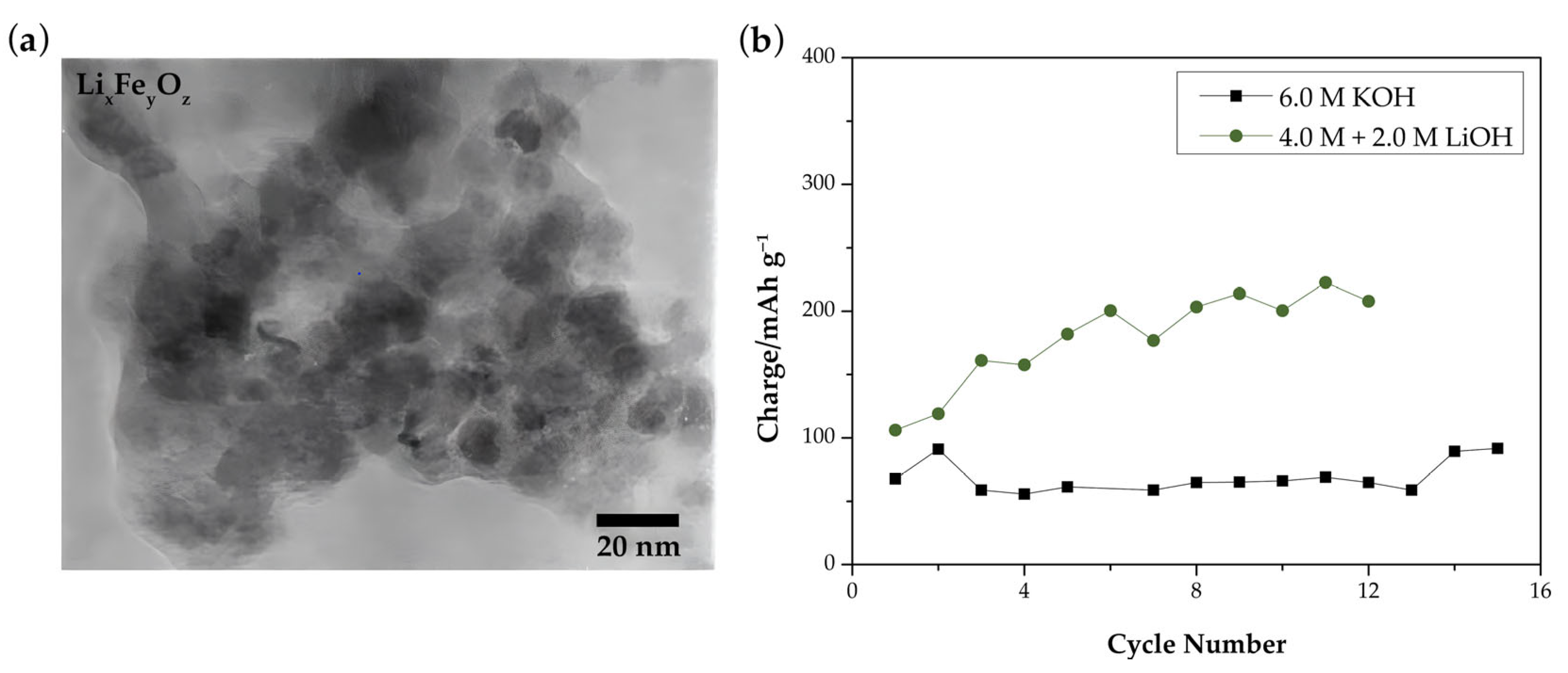
  161. Lee, Y.T.; Yoon, C.S.; Lee, Y.S.; Sun, Y.K. Synthesis and Structural Changes of LixFeyOz Material Prepared by a Solid-State Method. J. Power Sources 2004, 134, 88–94. [Google Scholar] [CrossRef]
  162. Ulman, A. Formation and Structure of SiB4. Am. Chem. Soc. 1996, 43, 1533–1554. [Google Scholar] [CrossRef]
  163. Whitesides, G.M.; Laibinis, P.E. Wet Chemical Approaches to The Characterization of Organic Surfaces: Self-Assembled Monolayers, Wetting, and The Physical-Organic Chemistry of The Solid-Liquid Interface. Langmuir 1990, 6, 87–96. [Google Scholar] [CrossRef]
  164. Qi, H.; Ren, Y.; Guo, S.; Wang, Y.; Li, S.; Hu, Y.; Yan, F. High-Voltage Resistant Ionic Liquids for Lithium-Ion Batteries. ACS Appl. Mater. Interfaces 2020, 12, 591–600. [Google Scholar] [CrossRef]
  165. Kong, L.; Tang, H.; Wang, X.; Lei, Y.; Li, B.; Chang, K.; Chang, Z. Study on the in Situ Sulfidation and Electrochemical Performance of Spherical Nickel Hydroxide. Int. J. Hydrogen Energy 2021, 46, 30079–30089. [Google Scholar] [CrossRef]
  166. Yu, D.; Chen, C.; Si, Y.; Zhou, S.; Wang, L. Study on the Electronic Structure of Nickel Hydroxide by Quantum Chemical DV-Xα Calculation. Chin. Sci. Bull. 2008, 53, 40–45. [Google Scholar] [CrossRef]
  167. Chen, J.; Bradhurst, D.H.; Dou, S.X.; Liu, H.K. Nickel Hydroxide as an Active Material for the Positive Electrode in Rechargeable Alkaline Batteries. J. Electrochem. Soc. 1999, 146, 3606–3612. [Google Scholar] [CrossRef]
  168. Wu, J.; Pan, Z.; Zhang, Y.; Wang, B.; Peng, H. The Recent Progress of Nitrogen-Doped Carbon Nanomaterials for Electrochemical Batteries. J. Mater. Chem. A 2018, 6, 12932–12944. [Google Scholar] [CrossRef]
  169. Tian, R.; Duan, H. Graphene-Based Materials for Advanced Lithium-Ion Batteries. In Handbook of Graphene: Energy, Healthcare, and Environmental Applications; Ozkan, C., Ozkan, U., Eds.; John Wiley & Sons, Inc.: Hoboken, NJ, USA, 2019; Volume 5. [Google Scholar]
  170. Ghosh Chaudhuri, R.; Paria, S. Core/Shell Nanoparticles: Classes, Properties, Synthesis Mechanisms, Characterization, and Applications. Chem. Rev. 2012, 112, 2373–2433. [Google Scholar] [CrossRef]
  171. Indira, L.; Dixit, M.; Kamath, P.V. Electrosynthesis of Layered Double Hydroxides of Nickel with Trivalent Cations. J. Power Sources 1994, 52, 93–97. [Google Scholar] [CrossRef] [Green Version]
  172. Freitas, M.B.J.G. Nickel Hydroxide Powder for NiO·OH/Ni(OH)2 Electrodes of the Alkaline Batteries. J. Power Sources 2001, 93, 163–173. [Google Scholar] [CrossRef]
  173. Kim, M.; Hwang, T.; Kim, K. A Study of the Electrochemical Redox Behavior of Electrochemically Precipitated Nickel Hydroxides Using Electrochemical Quartz Crystal Microbalance. J. Electrochem. Soc. 1997, 144, 1537–1543. [Google Scholar] [CrossRef]
  174. Zhong, H.; Liu, T.; Zhang, S.; Li, D.; Tang, P.; Alonso-Vante, N.; Feng, Y. Template-Free Synthesis of Three-Dimensional NiFe-LDH Hollow Microsphere with Enhanced OER Performance in Alkaline Media. J. Energy Chem. 2019, 33, 130–137. [Google Scholar] [CrossRef] [Green Version]
  175. Yan, F.; Zhu, C.; Li, C.; Zhang, S.; Zhang, X.; Chen, Y. Highly Stable Three-Dimensional Nickel–Iron Oxyhydroxide Catalysts for Oxygen Evolution Reaction at High Current Densities. Electrochim. Acta 2017, 245, 770–779. [Google Scholar] [CrossRef]
  176. Rosey, R. Westinghouse Nickel-Iron Battery Performance; Westinghouse Electric Corporation: Pittsburgh, PA, USA, 1981. [Google Scholar]
  177. Samy, M.M.; Emam, A.; Tag-Eldin, E.; Barakat, S. Exploring Energy Storage Methods for Grid-Connected Clean Power Plants in Case of Repetitive Outages. J. Energy Storage 2022, 54, 105307. [Google Scholar] [CrossRef]
  178. Kumar, P.P.; Saini, R.P. Optimization of an Off-Grid Integrated Hybrid Renewable Energy System with Different Battery Technologies for Rural Electrification in India. J. Energy Storage 2020, 32, 101912. [Google Scholar] [CrossRef]
  179. Kumar, P.P.; Suresh, V.; Jasinski, M.; Leonowicz, Z. Off-grid Rural Electrification in India Using Renewable Energy Resources and Different Battery Technologies with a Dynamic Differential Annealed Optimization. Energies 2021, 14, 5866. [Google Scholar] [CrossRef]
  180. Kumar, P.P.; Nuvvula, R.S.S.; Hossain, M.A.; Shezan, S.K.A.; Suresh, V.; Jasinski, M.; Gono, R.; Leonowicz, Z. Optimal Operation of an Integrated Hybrid Renewable Energy System with Demand-Side Management in a Rural Context. Energies 2022, 15, 5176. [Google Scholar] [CrossRef]
  181. Kumar, P.P.; Saini, R.P. Optimization of an Off-Grid Integrated Hybrid Renewable Energy System with Various Energy Storage Technologies Using Different Dispatch Strategies. Energy Sources Part A Recover. Util. Environ. Eff. 2020, 1–29. [Google Scholar] [CrossRef]
  182. Barakat, S.; Ibrahim, H.; Elbaset, A.A. Multi-Objective Optimization of Grid-Connected PV-Wind Hybrid System Considering Reliability, Cost, and Environmental Aspects. Sustain. Cities Soc. 2020, 60, 102178. [Google Scholar] [CrossRef]
  183. Eteiba, M.B.; Barakat, S.; Samy, M.M.; Wahba, W.I. Optimization of an Off-Grid PV/Biomass Hybrid System with Different Battery Technologies. Sustain. Cities Soc. 2018, 40, 713–727. [Google Scholar] [CrossRef]
  184. Hou, Z.; Zhang, X.; Li, X.; Zhu, Y.; Liang, J.; Qian, Y. Surfactant Widens the Electrochemical Window of an Aqueous Electrolyte for Better Rechargeable Aqueous Sodium/Zinc Battery. J. Mater. Chem. A 2017, 5, 730–738. [Google Scholar] [CrossRef]
  185. Kim, Y.; Kim, M.; Lee, T.; Kim, E.; An, M.; Park, J.; Cho, J.; Son, Y. Investigation of Mass Loading of Cathode Materials for High Energy Lithium-Ion Batteries. Electrochem. Commun. 2023, 147, 107437. [Google Scholar] [CrossRef]
  186. Manohar, A.K.; Malkhandi, S.; Yang, B.; Yang, C.; Surya Prakash, G.K.; Narayanan, S.R. A High-Performance Rechargeable Iron Electrode for Large-Scale Battery-Based Energy Storage. J. Electrochem. Soc. 2012, 159, A1209–A1214. [Google Scholar] [CrossRef]
Figure 1. Battery specifications of different commercial batteries [13].
Batteries 09 00383 g001
Figure 2. Schematic illustration of strategies towards Ni-Fe battery improvements (retrieved with permission from Ref. [36]. Copyright 2021, American Chemical Society).
Batteries 09 00383 g002
Figure 3. (a) Charge–discharge curve of Fe electrode (vs. Hg/HgO) in 6 M KOH (adapted with permission from Ref. [41]. Copyright 1991, Elsevier). (b) Fe anode passivation process during cycling (adapted with permission from Ref. [39]. Copyright 2018, American Chemical Society).
Batteries 09 00383 g003
Figure 4. Schematic illustration of Ni(OH)2 polymorphs’ crystal structures (adapted with permission from Ref. [56]. Copyright 2018, American Chemical Society) (adapted with permission from Ref. [35]. Copyright 2020, Springer).
Batteries 09 00383 g004
Figure 5. Cross-sectional schematic of Fe electrode passivation from early discharge stage to final discharge stage (adapted with permission from Ref. [46]. Copyright 2017, Electrochemical Society).
Batteries 09 00383 g005
Figure 6. (a) Illustration (top) and TEM images (bottom) of the vines-grapes-like Fe3O4–NGC composites (reprinted with permission from Ref. [65]. Copyright 2021, Elsevier). (b) Schematic evolution of Fe⊂C nanopopcorns (reprinted with permission from Ref. [78]. Copyright 2019, American Chemical Society). (c) SEM images of sintered Fe electrode surface before and after 40 cycles (reprinted with permission from Ref. [46]. Copyright 2017, Electrochemical Society). (d) SEM images of pressed-plate Fe electrode surface before and after electrode formation (reprinted with permission from Ref. [117]. Copyright 2018, Springer).
Batteries 09 00383 g006
Figure 7. Discharge profiles of: (a) pure Fe and various Fe:Cu composites at a constant current of 200 mAh g−1; and (b) Fe:Cu (weight ratio = 2:1) composite at different current densities (adapted with permission from Ref. [109]. Copyright 2011, Elsevier).
Batteries 09 00383 g007
Figure 8. (a) Schematic illustration of the self-adapting mechanism of thick C nanoreactors; and (b) the cyclic behavior and TEM observations on pristine and cycled Fe@TCNRs (adapted with permission from Ref. [102]. Copyright 2017, The Royal Society of Chemistry).
Batteries 09 00383 g008
Figure 9. (a) Schematic of cycling behavior of Fe electrode with Bi2S3, and Bi2O3 + FeS (adapted with permission from Ref. [23]. Copyright 2015, Electrochemical Society); (b) discharge capacity vs. C-rate of Fe electrode with additives (adapted with permission from Ref. [44]. Copyright 2013, Electrochemical Society); and (c) cyclic performance of Fe3O4, Fe3O4/MoS2, Fe3O4/NiS, and Fe3O4/MoS2/NiS at 0.3 A g−1 (adapted with permission from Ref. [114]. Copyright 2022, MDPI).
Batteries 09 00383 g009
Figure 10. (a) TEM bright-field image of LixFeyOz prepared at 200 °C (retrieved with permission from Ref. [161]. Copyright 2004, Journal of Power Sources); (b) Charge capacity of FeO electrodes in 6.0 M KOH (square) and 4.0 M + 2.0 M LiOH (circle) (adapted with permission from Ref. [153]. Copyright 2006, Elsevier).
Batteries 09 00383 g010
Figure 11. (a) Schematic diagram of Fe anode surface in an electrolyte solution containing Na2S additives (adapted with permission from Ref. [156]. Copyright 2018, Elsevier). (b) Cyclic voltammogram of porously sintered iron electrodes in KOH electrolyte solution and (c) KOH with 0.05% K2S. (d) First discharge curves obtained from porous sintered Fe electrodes with various additives and (adapted with permission from Ref. [148]. Copyright 2017, Electrochemical Society).
Batteries 09 00383 g011
Figure 12. (a) Schematic diagram of self-assembled monolayers of alkanethiol additives on Fe surface. (b) Effect on alkanethiol chain length on hydrogen evolution current on pure Fe disk electrodes (adapted with permission from Ref. [157]. Copyright 2012, American Chemical Society). (c) Hydrogen evolution reduction percentages of various organo-sulfur compound additives (1: 1-dodecanethiol; 2: 1-octanethiol; 3: 1-propanethiol; 4: 3,6-dioxa-1,8-octanedithiol; 5: 1,2-ethanedithiol; 6: 1,4-dithiane; 7: Bismethyldithiomethane; 8: Benzenethiol; 9: 2-methylbenzenethiol) (adapted with permission from Ref. [151]. Copyright 2014, The Royal Society of Chemistry).
Batteries 09 00383 g012
Figure 13. (a) Schematic representation of metal oxide electrode preparation using novel in situ zinc sacrifice method and (b) the SEM images of NiOx products (adapted with permission from Ref. [79]. Copyright 2017, Wiley-VCH Verlag GmbH & Co. KGaA, Weinheim). (c) FESEM images of PTFE corroded nickel electrodes (retrieved with permission from Ref. [82]. Copyright 2020, Wiley-VCH Verlag GmbH & Co. KGaA, Weinheim). (d) SEM (top) and TEM (bottom) images of NCO nanowire arrays (retrieved with permission from Ref. [110]. Copyright 2018, The Royal Society of Chemistry). (e) Schematic illustration of liquid phase epitaxy growth mechanism (retrieved with permission from Ref. [64]. Copyright 2020, Elsevier). (f) Illustration of novel NiCo2O4-CNT-S-PEGm electrode with flower-like microstructure (retrieved with permission from Ref. [65]. Copyright 2021, Elsevier).
Batteries 09 00383 g013
Figure 14. Characterization of phosphated Ni-Co hydroxides via (a) SEM and (b) XRD (retrieved with permission from Ref. [83]. Copyright 2020, American Chemical Society). Curves of discharge capacity vs. cycle number obtained for: (c) Ni1−xMgx(OH)2 (left) and (d) Ni1−xMnx(OH)2 formulations (adapted with permission from Ref. [50]. Copyright 2021, Elsevier).
Batteries 09 00383 g014
Figure 15. (a) TEM image of Ni(OH)2/MWCNTs (retrieved with permission from Ref. [16]. Copyright 2012, Nature Portfolio). (b) Electrochemical performance measurements for Ni(OH)2/MWCNT cathode materials (retrieved with permission from Ref. [16]. Copyright 2012, Nature Portfolio). (c) SEM images of Ni(OH)2 before (leftmost 3) and after (rightmost 3) sulfurization (retrieved with permission from Ref. [165]. Copyright 2021, Elsevier). (d) SEM images of CoP nanowire arrays on CNTF (top) and CoP@Ni(OH)2 NWAs/CNTF (bottom) (retrieved with permission from Ref. [95]. Copyright 2019, The Royal Society of Chemistry). (e) SEM images of 3D-NA/NiZn treated with inositol hexaphosphoric acid (adapted with permission from Ref. [104]. Copyright 2017, The Royal Society of Chemistry).
Batteries 09 00383 g015
Figure 16. (a) Schematic diagram of flexible batteries (retrieved with permission from Ref. [95]. Copyright 2019, The Royal Society of Chemistry). (b) Capacity retention of Ni-Fe batteries in aqueous (black box) and quasi-solid-state (green star) electrolyte (retrieved with permission from Ref. [77]. Copyright 2018, The Royal Society of Chemistry).
Batteries 09 00383 g016
Figure 17. (a) Schematic diagram of battolyser. (b) Experimental and simulation results of cell potential during (dis)charge cycles at constant current (C/5 rate equal to 2 A) (retrieved with permission from Ref. [36]. Copyright 2021, American Chemical Society).
Batteries 09 00383 g017
Table 1. Comparison of the electrochemical performances of different Fe-based electrodes.
Anode MaterialPreparationElectrolyteVoltage
Window
Specific
Capacity
Capacity RetentionRef.
FeOx/graphene
nanocomposites
Solution phase reaction and gas phase annealing1 M KOH−1.3 to −0.5 V
vs. SCE
377 mAh g−1
at 5 mV s−1
-[16]
Fe3O4@C microspheresSpray drying6 M KOH
+15 g L−1 LiOH
+0.1% Na2S
−1.2 to −0.4 V
vs. Hg/HgO
556.7 mAh g−1
at 1.2 A g−1
92% after 100
cycles at 0.3 A g−1
[21]
Core–shell Fe3O4@MoO2 -CElectrodeposition3 M KOH−1.2 to 0 V
vs. Hg/HgO
155.6 mAh g−1
at 1.1 A g−1
-[22]
Core–shell C-FeAerosol-assisted spray pyrolysis1 M KOH−1.6 to 0 V
vs. SCE
208 mAh g−1
at 1 A g−1
93% after 2000
cycles at 4 A g−1
[27]
Core–shell Fe@CPyrolysis1 M KOH−1.6 to 0 V
vs. SCE
314 mAh g−1
at 1 A g−1
90% after 1000
cycles at 10 mV s−1
[28]
α-Fe2O3@PPy
nanorods/CNTF
Hydrothermal synthesis and annealing3 M KOH−1.6 to 0 V
vs. Ag/AgCl
0.62 Ah cm−3
at 1 A cm−3
-[29]
Fe3O4@C mesoporous nanoarraysSelf-generated sacrificial template 2 M KOH−1.2 to −0.2 V
vs. SCE
292.4 mAh g−1
at 5 mA cm−2
90.8% after 5000
cycles at 30 mA cm−2
[30]
Fe/Cu nanocompositesCathodic decomposition8 M KOH
+ 0.05M Na2S
−1.3 to 0 V
vs. Hg/HgO
~350 mAh g−1 Fe
at 0.05 A g−1
-[31]
3D-Fe/Fe2O3@CAnnealing1 M KOH−1.2 to 0 V
vs. Hg/HgO
3.07 mAh cm−2
at 6 mA cm−2
80% after 20,000
cycles at 100 mA cm−2
[63]
Fe3O4-NGC
(vines-grapes-like)
Hydrothermal synthesis6 M KOH−1.4 to 0 V
vs. Ag/AgCl
308.1 mAh g−1
at 1 A g−1
-[65]
GE@CNT-Fe-Fe3C/CFMicrowave-assisted synthesis1 M KOH−1.2 to −0.2 V
vs. Hg/HgO
1.74 mAh cm−3
at 1 mA cm−1
106.5% after 20,000
cycles at 8 mA cm−2
[66]
Fe3O4@Ni3S2 microspheresHydrothermal synthesis6 M KOH−1.0 to −0.4 V
vs. Hg/HgO
~481.2 mAh g−1
at 1.2 A g−1
95.1% after 100
cycles at 1.2 A g−1
[67]
Fe3O4@C
(micrododecahedral)
Hydrothermal synthesis6 M KOH−1.4 to −0.4 V
vs. Hg/HgO
419 mAh g−1
at 0.6 A g−1
40% after 500
cycles at 0.3 A g−1
[76]
α-Fe2O3 nanorodsHydrothermal synthesis1 M KOH−1.2 to −0.2 V
vs. SCE
308.9 mAh g−1
at 1 A g−1
96.1% after 2000
cycles at 5 mV s−1
[77]
FeÌC nanopopcornsSolid-state synthesis3 M KOH−1.4 to −0.3 V
vs. Ag/AgCl
~480.5 mAh g−1
at ~1 A g−1
~95.8% after 4000
cycles at 2 A g−1
[78]
FeOx nanowiresElectrodeposition6 M KOH−1.4 to −0.4 V
vs. Hg/HgO
0.32 mAh cm−2
at 20 mA cm−2
-[79]
FeOOH nanorodsElectrodeposition1 M KOH−1.2 to −0.4 V
vs. Hg/HgO
184 mAh g−1
at 2 A g−1
87.5% after 5000
cycles at 5 A g−1
[80]
rGO/CNTs@α-Fe2O3Hydrothermal synthesis3 M KOH−1.2 to 0 V
vs. Ag/AgCl
~486.5 mAh g−1
at 10 mA cm−2
93.6% after 5000
cycles at 200 mA cm−2
[81]
C@Fe-based/Bi/FF
(flower-like)
Calcination6 M KOH−1.4 to 0 V
vs. Hg/HgO
2.83 mAh cm−2
at 10 mA cm−2
92.86% after 25,000
cycles at 10 mA cm−2
[82]
FeP nanowire
arrays/CNTF
Hydrothermal synthesis1 M KOH−1.25 to 0 V
vs. Ag/AgCl
0.634 mAh cm−2
at 2 mA cm−2
89% after 4000
cycles at 10 mV s−1
[83]
Fe2O3-S@C nanorodsHydrothermal synthesis and plasma enhanced chemical vapor deposition1 M KOH−1.2 to 0 V
vs. Hg/HgO
224 mAh g−1
at 0.8 mA cm−2
92.2% after 100
cycles at 1 mA cm−2
[84]
mc-FeOx/C nanocrystalsMolecular confinement 1 M KOH−1.4 to 0 V
vs. SCE
370.2 mAh g−1
at 2 A g−1
93.5% after 1000
cycles at 2 A g−1
[85]
Mesostructured
carbon/Fe/FeO/Fe3O4
Solid-state reaction4 M KOH
+ 2% LiOH
−1.2 to 0 V
vs. Hg/HgO
604 mAh g−1
at 1 A g−1
~77.3% after 1000
cycles at 1 A g−1
[86]
Fe3O4 mesoporous sheetsEtching6 M KOH
+ 0.5 M LiOH
−1.2 to −0.4 V
vs. Hg/HgO
205.7 mAh g−1
at 0.2 A g−1
60.2% after 250
cycles at 0.2 A g−1
[87]
S-Fe2O3/CNTF
nanowire arrays
Hydrothermal synthesis and in situ sulfurization-−1.4 to 0 V
vs. Ag/AgCl
0.81 mAh cm−2
at 4 mA cm−2
92.4% after 5000
cycles at 40 mA cm−2
[88]
Fe3O4 + 5% CuSO4•5H2OCommercial powders6 M KOH−1.3 to −0.3 V
vs. Hg/HgO
221 mAh g−1
at 0.9 A g−1
85.7% after 50
cycles at 0.225 A g−1
[89]
FeCu0.25/15%FeS/5%C (spherical polyhedral)Autocatalytic Cu and electroless Fe deposition6 M KOH
+ 1 M LiOH
−1.4 to −0.4 V
vs. Hg/HgO
~278 mAh g−1
at 0.6 A g−1
85% after 40
cycles at 0.1 A g−1
[90]
Fe@CMFs
(nanometal-inlaid fibers)
Colloid-assisted synthesis3 M KOH−1.35 to −0.35 V
vs. Ag/AgCl
348 mAh g−1
at 2 A g−1
~80% after 4000
cycles at 2 A g−1
[91]
Fe1-xS@rGO nanosheetsHydrothermal synthesis1 M KOH−1.2 to −0.2 V
vs. SCE
~270 mAh g−1
at 1 A g−1
83.3% after 100
cycles at 1 A g−1
[92]
FeOOH@rGO nanorodsHydrothermal synthesis3 M KOH−1.0 to 0 V
vs. SCE
180 C g−1
at 1 A g−1
66% after
- cycles at 10 A g−1
[93]
Core–shell Fe@C
nanoparticles
One-step chemical vapor deposition3 M KOH−1.4 to −0.35 V
vs. Ag/AgCl
~405.2 mAh g−1
at 1 A g−1
~91.9% after 4000
cycles at 5 A g−1
[94]
S-α-Fe2O3@CNTF
(spindle-like)
Hydrothermal synthesis3 M KOH−1.2 to −0.4 V
vs. Hg/HgO
556.7 mAh g−1
at 1.2 A g−1
76.8% after 6000
cycles at 20 mA cm−2
[95]
LiFe3PO4/C/FeS spheresBall milling6 M KOH−1.2 to −0.4 V
vs. Hg/HgO
~232.9 mAh g−1
at 0.2 C
75.9% after 300
cycles at 1 C
[96]
CuxFe3-xO4
(honeycomb-like)
Co-precipitation method8 M KOH
+ 0.05 M Na2S
−1.2 to −0.8 V
vs. Hg/HgO
230 mAh g−1
at 1 C
-[97]
Mn-Fe2O3 nanoplatesElectrodeposition and electrochemical activation1 M KOH−1.2 to −0.4 V
vs. Hg/HgO
174 mAh g−1
at 8.3 mA cm−2
~97% after 10,000
cycles at 20 mV s−1
[98]
Core–shell Fe3O4@CPolymeric process and magnetic purification3 M KOH−1.35 to −0.4 V
vs. Ag/AgCl
~285 mAh g−1
at ~0.8 A g−1
-[99]
NiS-Fe3O4 nanoparticlesCo-precipitation method6 M KOH
+ 15 g L−1
+ 0.1% Na2S
−1.25 to −0.4 V
vs. Hg/HgO
472.7 mAh g−1
at 1.2 A g−1
85.9% after 100
cycles at 0.3 A g−1
[100]
Core–shell Fe3O4@NiSSedimentation-oxygenation method6 M KOH−1.4 to −0.4 V
vs. Hg/HgO
346 mAh g−1
at 1.5 C
85% after 50
cycles at 0.15 C
[101]
Core–shell Fe@TCNRsGas-phase reactions3 M KOH−1.4 to −0.3 V
vs. Ag/AgCl
~491 mAh g−1
at ~1 A g−1
~97.8% after 4000
cycles at 4 A g−1
[102]
Core–bishell
Fe-Ni@Fe3O4@C
Pyrolysis6 M KOH
+ 0.35 M LiOH
+ 0.05 M Na2S
−1.2 to −0.2 V
vs. Hg/HgO
320 mAh g−1
at 1 A g−1
~91.7% after 100
cycles at 1 A g−1
[103]
3D-nanoarrays/Fe-phytateElectrodeposition and phytic acid treatment6 M KOH−1.3 to −0.3 V
vs. Hg/HgO
223.6 mAh g−1
at 3.85 A g−1
114% after 3000
cycles at 76.92 A g−1
[104]
Core–shell 3D hierarchical CC/CF@Fe3O4 (needle-like)Electrodeposition and hydrothermal growth2 M KOH−1.2 to 0 V
vs. Hg/HgO
207.6 mAh g−1
at 5 mA cm−2
83.4% after 1000
cycles at 5 mA cm−2
[105]
FeOx-graphene nanocomposites + 5 wt% Bi2O3Solid-state synthesis8 M KOH
+ 1 M LiOH
−1.4 to −0.4 V
vs. Hg/HgO
408.5 mAh g−1
at 1 A g−1
90% after 100
cycles at 1 A g−1
[106]
Core–shell Fe/C
nanoparticles
Chemical reduction8 M KOH
+ 1 M LiOH
−1.4 to −0.4 V
vs. Ag/AgCl
600 mAh g−1Fe
at 0.2 A g−1
~66.7% after 40
cycles at 0.2 A g−1
[107]
Fe2O3/MWCNTCommercial powders6 M KOH−1.2 to −0.3 V
vs. Hg/HgO
350 mAh g−1
at 10 mA cm−2
-[108]
Core–shell Fe/Cu
nanoparticles
Chemical reduction8 M KOH
+ 1 M LiOH
−1.4 to −0.2 V
vs. Ag/AgCl
800 mAh g−1 Fe
at 0.2 A g−1
-[109]
GF/CNTs/Fe2O3
nanocomposites
Hydrothermal synthesis and annealing6 M KOH−1.2 to −0.2 V
vs. SCE
278 mAh g−1
at 1 A g−1
96% after 1000
cycles at 10 mV s−1
[110]
Fe3O4/OG
(3D nanostructures)
Electrodeposition6 M KOH−1.2 to −0.5 V
vs. Hg/HgO
634 mAh g−1
at 5 A g−1
~80% after 2000
cycles at 5 A g−1
[111]
Fe/Fe3O4@CF
(rock-like nanocomposites)
Electrodeposition
and annealing
1 M KOH−1.4 to 0 V
vs. Hg/HgO
163.03 mAh g−1
at 3.43 A g−1
91.7% after 6000
cycles at 16 mA cm−2
[112]
Cu-doped Fe3O4
(3D coral-like structure)
Hydrothermal synthesis1 M KOH−1.0 to 0 V
vs. Hg/HgO
117.5 mAh g−1
at 1 A g−1
97.6% after 10,000
cycles at 5 A g−1
[113]
Fe3O4/MoS2(5%)/NiS(5%)
nanospheres
Chemical co-precipitation6 M NaOH
+ 0.6 M LiOH
−1.25 to −0.4 V
vs. Hg/HgO
639.8 mAh g−1
at 1.2 A g−1
84.9% after 100
cycles at 1.2 A g−1
[114]
α-Fe2O3@NC-CTs (3D
hollow nanowall arrays)
Seed-assisted hydrothermal synthesis and annealing3 M KOH−1.4 to 0 V
vs. Ag/AgCl
249.9 mAh cm−2
at 5 mA cm−2
~81.9% after 5000
cycles at 30 mA cm−2
[115]
Table 2. Comparison of the electrochemical performances of different Ni-based electrodes.
Cathode Material PreparationElectrolyte Voltage
Window
Specific
Capacity
Capacity Retention Ref.
Ni(OH)2@MWCNTs
nanoplates
Hydrothermal
synthesis
1 M KOH0 to 0.6 V
vs. SCE
228 mAh g−1
at ~7.46 A g−1
-[16]
α-Ni(1-x)Fex(OH)2
(layered double
hydroxides)
Co-precipitation method6 M KOH0 to 0.6 V
vs. Hg/HgO
724 mAh g−1
at 0.1 C
90% after 1000
cycles
[18]
Ni0.95Mg0.5(OH)2Co-precipitation and
hydrothermal treatment
4 M KOH0 to 0.7 V
vs. Hg/HgO
178.4 mAh g−1
at 250 mA g−1
88% after 100
cycles
[50]
Ni0.95Mn0.5(OH)2181.2 mAh g−1
at 250 mA g−1
85% after 100
cycles
Ni(OH)2 nanosheets/FGSLiquid phase epitaxy1 M KOH0 to 0.5 V
vs. SCE
228.3 mAh g−1
at 1 A g−1
86.1% after 5000
cycles at 10 A g−1
[64]
NiCo2O4-CNT-S-PEGm (flower-like microspheres with honeycomb-like ion buffer reservoir)Thiol-ene click modification and solvothermal method with sintering6 M KOH−0.1 to 0.5 V
vs. Ag/AgCl
195.7 mAh g−1
at 0.5 A g−1
84.9% after 2000
cycles at 4 A g−1
[65]
P-NiCo2O4/CC
(nanowires array)
Electrolytic deposition
and phytic acid treatment
6 M KOH−0.2 to 0.8 V
vs. Hg/HgO
247 mAh g−1
at 1 A g−1
96.5% after 2000
cycles
[77]
NiOx nanoflakes on CC-CF substrate Chemical deposition
with post-annealing
2 M KOH−0.2 to 0.6 V
vs. Hg/HgO
39.7 mAh g−1
at 1.68 A g−1
-[79]
NiO-NiF2/NF
nanoparticles
Calcination6 M KOH0 to 0.7 V
vs. Hg/HgO
1.24 mAh cm−2
at 5 mA cm−2;
0.69 mAh cm−2
at 40 mA cm−2
84% after 1000
cycles at 40 mA cm−2
[82]
NiCoP nanosheet
arrays/CNTF
Hydrothermal synthesis and phosphating1 M KOH0 to 0.5 V
vs. Ag/AgCl
0.55 mAh cm−2
at 2 mA cm−2
90% after 4000
cycles
[83]
Ni-Mn Hydroxide nanosheets/Ni3S2Hydrothermal
synthesis
3 M KOH−0.1 to 0.6 V
vs. SCE
385.17 mAh g−1
at 1 A g−1
79% after 5000
cycles
[93]
Core–shell CoP
Nanowire arrays@Ni(OH)2 nanosheets
Hydrothermal synthesis
and phosphating
3 M KOH0 to 0.6 V
vs. Ag/AgCl
0.689 mAh cm−2
at 2 mA cm−2
85.4% after 15,000
cycles at 20 mA cm−2
[95]
NiZn-Phytate
(on 3D-Cu nanowire network)
In situ sacrifice of Zn
via cyclic voltammetry
6 M KOH−0.2 to 0.8 V
vs. Hg/HgO
462.02 mAh g−1
at 4.5 A g−1
76% after 7000
cycles at 45.45 A g−1
[104]
Ni(OH)2 nanospheres@NiSAtmospheric reflux
in water
6 M KOH + 0.63 M LiOH0 to 0.8 V
vs. Hg/HgO
168.7 mAh g−1
at 5 C
87.3% after 100
cycles at 5 C;
90% after 100
cycles at 10 C
[165]
Table 3. Summary of the electrochemical performance of different flexible nickel-iron batteries reported.
Anode
Material
Cathode
Material
Operating VoltageSpecific
Capacity
Energy
Density
Capacity
Retention
Capacity Retention after Mechanical DeformationRef.
α-Fe2O3@
PPy NRs/
CNTF
CoNiO2@
Ni(OH)2 NWAs/
CNTF
1.6 V70 mAh cm−3
at 1 A cm−3
15.47 mWh cm−3
at 228.2 mW cm−3
70.6% after 6000
cycles at 5 A cm−3
90.1% after
2500 cycles at
1 A cm−3 and 180° bending
[29]
3D-Fe/
Fe2O3@C
NiCo2O42.0 V1.02 mAh cm−2
at 5 mA cm−2
15.53 mWh cm−3
at 30.48 W cm−3
84.8% after
20,000 cycles at
50 mA cm−2
100% after
bending at 180°
[63]
GE@
CNT-Fe-Fe3C/CF
GE@
NiCoO/CF
1.8 V1.61 mAh cm−3
at 0.3 mA
1.28 mWh cm−3
at 18.32 mW cm−3
94.7% after
20,000 cycles at
5 mA
100% after
bending at 180°
[66]
Fe2O3 nano
rods
P-NiCo2O4 nanowires1.6 V134.5 mAh g−1
at 1 A g−1
227 Wh kg−1
at 0.59 kW kg−1
82.7% after
2600 cycles at
2 A g−1
99% after
bending
[77]
FeOx nano
wires
NiOx nanoflakes1.0 V6.91 mAh cm−3
at 5 mA cm−3
7.40 Wh cm−3
at 0.27 W cm−3
75% after 1000
cycles at
20 mA cm−2
100% after
twisting
[79]
3D rGO/
CNTs@
α-Fe2O3
3D rGO/
CNTs@
Ni(OH)2
2.0 V206.4 mAh g−1
at 10 mA cm−2
28.1 mWh cm−3
at 10.6 mW cm−3
91.3% after 10,000 cycles at
300 mA cm−2
84.5% after
2000 cycles at
200 mA cm−3, 60% compression strain
[81]
FeP NWAs/
CNTF
NiCoP NSAs/CNTF1.6 V0.294 mAh cm−2
at 2 mA cm−2
235.6 μWh cm−288% after 4000
cycles at 2 mA cm−2
100% after
3000 times
bending at 180°
[83]
S-Fe2O3 NWAs/
CNTFs
ZNCO@
Ni(OH)2 NWAs
1.05 V0.46 mAh cm−2
at 2 mA cm−2
67.32 mWh cm−3
at 591.12 mW cm−3
90.2% after
3000 cycles at
10 mA cm−2
94.8% after
4000 cycles at
2 mA cm−2 and 90° bending
[88]
S-α-Fe2O3/
CNTF
CoP@
Ni(OH)2 NWAs/
CNTF
1.6 V0.203 mAh cm−2
at 3 mA cm−2
81 mWh cm−3
at 1200 mW cm−3
85.3% after
3000 cycles at
30 mA cm−2
92.4% after
3000 cycles at
6 mA cm−2 and 90° bending
[95]
Mn-Fe2O3Mn-NiO2.0 V46 mAh cm−3
at 2.5 A cm−3
61 mWh cm−3
at 48.4 W cm−3
91.5% after
30,000 cycles at
20 mA cm−3
96.2% at
10 A cm−3 after
200 times bending at 90°
[98]
3D-NA/Fe-phytate3D-NA/
NiZn-phytate
2.0 V225.75 mAh g−1
at 0.46 A g−1
185.33 Wh kg−1
at 15.93 kW kg−1
86% after
8000 cycles at
20.83 A g−1
100% after
bending at 180°
[104]
CC-CF@
Fe3O4
CC-CF@NiO1.6 V88.2 mAh g−1
at 5 mA cm−2
94.5 Wh kg−1
at 1.2 kW kg−1
80.7% after
2600 cycles
97% after twisting and bending[105]
GF/CNTs/Fe2O3GF/CNTs/
Ni(OH)2
1.6 V118 mAh g−1 at 0.3 A g−1100.7 Wh kg−1
at 287 Wh kg−1
89.1% after
1000 cycles at
1.3 A g−1
100% after
bending at 60°
[110]
Fe/Fe3O4@CFNi(OH)2@CF1.7 V0.466 mAh cm−2 at 10 mA cm−21.14 mWh cm−3
at 34 mW cm−3
86.2% after
6000 cycles at
16 mA cm−2
100% after
bending at 180°
[112]
Cu-doped Fe3O4NiCoS41.6 V49.02 mAh g−1
at 1 A g−1
45.6 Wh kg−1
at 12 kW kg−1
96.8% after
10,000 cycles at
5 A g−1
-[113]
α-Fe2O3@
NC/CTs
Ni(OH)2@NC/CTs2.10 V94.8 mAh g−1
at 5 mA cm−2
155.4 Wh kg−1 at 1.75 kW kg−186.1% after
10,000 cycles at
30 mA cm−2
100% after
bending at 135°
[115]
Disclaimer/Publisher’s Note: The statements, opinions and data contained in all publications are solely those of the individual author(s) and contributor(s) and not of MDPI and/or the editor(s). MDPI and/or the editor(s) disclaim responsibility for any injury to people or property resulting from any ideas, methods, instructions or products referred to in the content.

