Article

Concepts for Reusing Composite Materials from Decommissioned Wind Turbine Blades in Affordable Housing

1
City College of New York, Grove School of Engineering, New York, NY 10031, USA
2
Georgia Institute of Technology, School of Architecture, Atlanta, GA 30332, USA
3
David Keir Building, Queen’s University Belfast, Stranmillis Road, Belfast BT9 5AG, UK
*
Author to whom correspondence should be addressed.
Recycling 2018, 3(1), 3; https://doi.org/10.3390/recycling3010003
Submission received: 5 December 2017 / Revised: 16 January 2018 / Accepted: 16 January 2018 / Published: 17 January 2018

Abstract

:
The very rapid growth in wind energy technology in the last 15 years has led to a rapid growth in the amount of non-biodegradable, thermosetting fiber reinforced polymer (FRP) composite materials used in wind turbine blades. This paper discusses conceptual architectural and structural options for recycling these blades by reusing parts of wind turbine blades in new or retrofitted housing projects. It focuses on large-sized FRP pieces that can be salvaged from the turbine blades and can potentially be useful in infrastructure projects where harsh environmental conditions (water and high humidity) exist. Since reuse design should be for specific regional locations and architectural characteristics the designs presented in this paper are for the coastal regions of the Yucatan province in Mexico on the Gulf of Mexico where low-quality masonry block informal housing is vulnerable to severe hurricanes and flooding. To demonstrate the concept a prototype 100 m long wind blade model developed by Sandia National Laboratories is used to show how a wind blade can be broken down into parts, thus making it possible to envision architectural applications for the different wind blade segments for housing applications.

1. Introduction

A typical 2.0 MW turbine with three 50 m blades has approximately 20 tonnes of fiber reinforced polymer (FRP) material and an 8 MW turbine has approximately 80 tonnes of glass (G) and carbon (C) fiber reinforced polymer (FRP) material (1 MW ~ 10 tonnes of FRP, see [1,2,3,4].) As of December 2016, the global cumulative installed wind power capacity was 486,790 MegaWatts (MW) (Figure 1) [5]. Based on a predicted moderate growth scenario from the Global Wind Energy Council [6] for future global wind power installations a total of 16.8 million tonnes of FRP materials will need to be disposed of or recycled by 2030 and 39.8 million tonnes by 2050 (Figure 2). However beneficial to sustainable energy production, this sharp growth in the wind industry will also lead to substantial and potentially unsustainable amounts of non-biodegradable composite material to be dealt with in the future.
The Mexican wind industry has been installing wind turbines over the past nine years. Figure 3 shows a forecast of the installed capacity (12,823 MW total) for each of Mexico’s provinces in 2020 [7]. The two provinces with the largest anticipated wind energy capacities in 2020 are Oaxaca and Yucatan. Large numbers of wind turbine blades facing inevitable decommissioning close to vulnerable communities on the Gulf of Mexico coast would make it feasible to transport blade segments to these communities for reuse.
Over the past 40 years formal and informal settlements have developed in small towns along the northern coast of the Yucatan in the Gulf of Mexico. To assess the vulnerability of these settlements to the effects of climate change, 628 household surveys were conducted in seven communities in his region in the summer of 2014 [8]. The housing in this region is constructed of hollow concrete (CMU) blocks confined by cast-in-place corner columns. The roof is constructed of precast inverted T-beams and matching hollow blocks. After assembly the roof is covered with a 15–20 mm layer of cast-in-place pea-gravel concrete. The foundation is compacted rubble with a cast-in-place strip footing. Concrete lintels and header beams are cast-in-place. Houses are typically single or multi-room measuring 30–50 m2. A house under construction is shown in Figure 4. The edge of the roofing system can be seen on the house alongside to the left in Figure 4. The interior of an approximately 30 year old house is shown in Figure 5. The underside of the inverted-T-beam and the roofing blocks can be seen. Severe effects of moisture damage to both the roof and walls is also observed. The household surveys revealed that home owners were most concerned about the damage caused by wind-driven rain and flooding due to hurricanes and also normal weather conditions [8].
Three end-of-life (EOL) options for FRP wind blades [9] are currently possible—disposal, recovery, and reuse. The two options to dispose of FRP composites at the present involve landfilling or incineration (with or without energy recovery and/or silica ash recovery). Recovery options consist of reclamation of the constituent fibers or the resins by thermo–chemical methods or recovering of small pieces of granular FRP material for use as filler material in concrete or other composites by cutting, shredding, or grinding [10,11]. Reuse options consist of reusing the entire FRP blade or large parts of it in new structural applications. Reuse options are the primary focus of this paper since landfilling and incineration are environmentally harmful and recovery methods are not currently economical for glass fiber reinforced polymer (GFRP), of which the vast majority of current blades are fabricated. There is significant current research [10] in recovering carbon fiber reinforced polymer (CFRP) materials which have higher value as recycled materials.

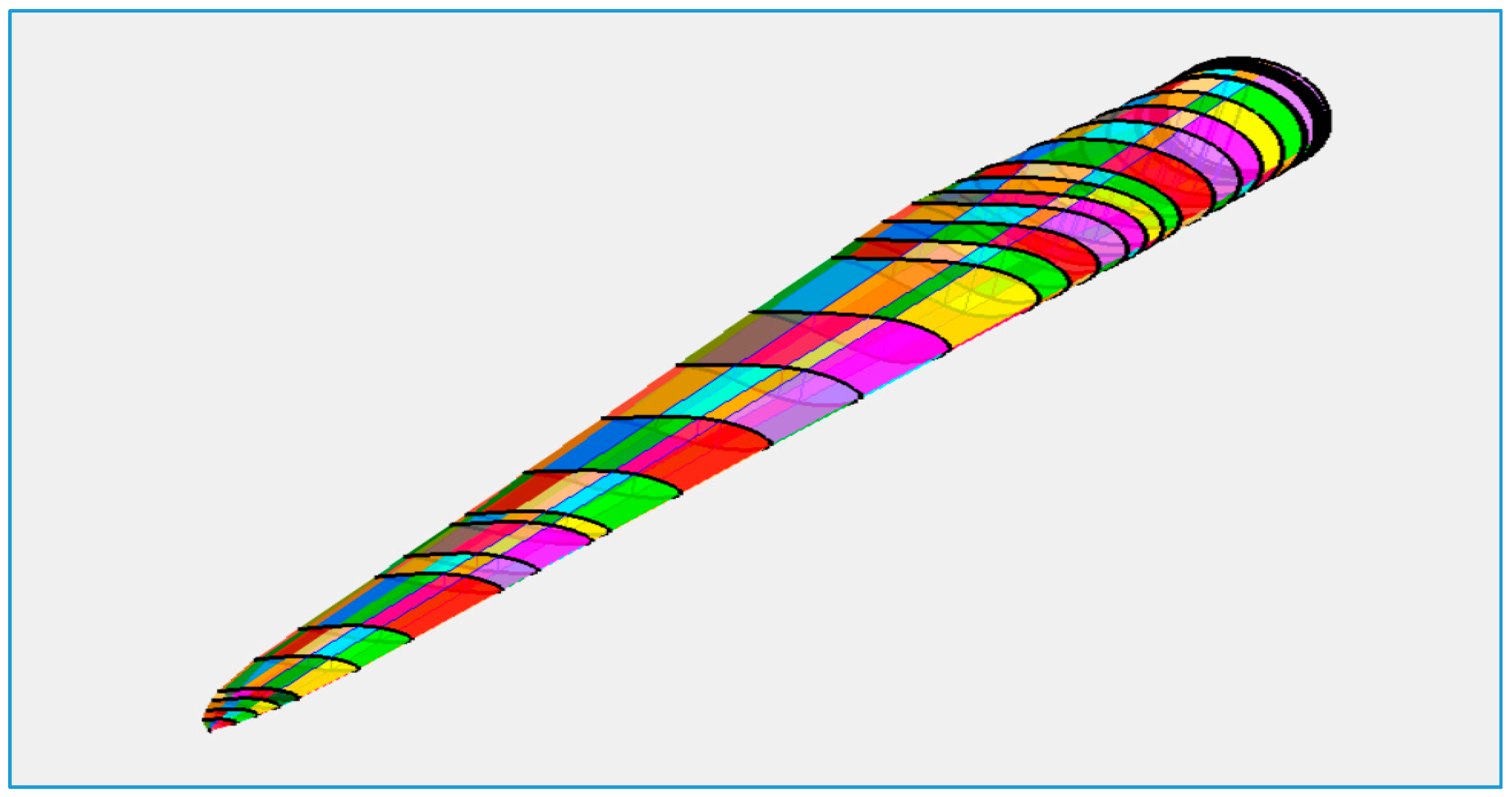
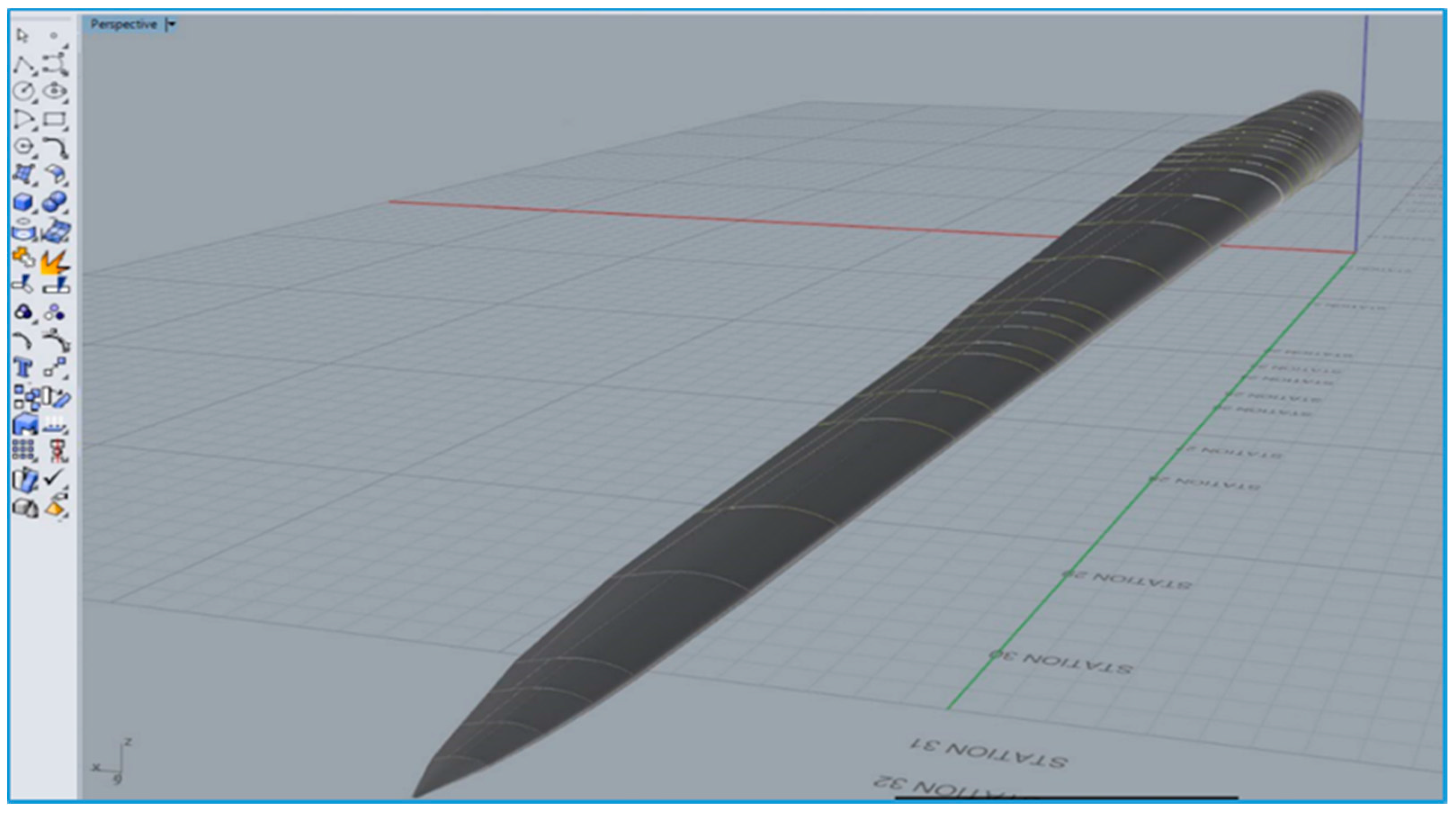
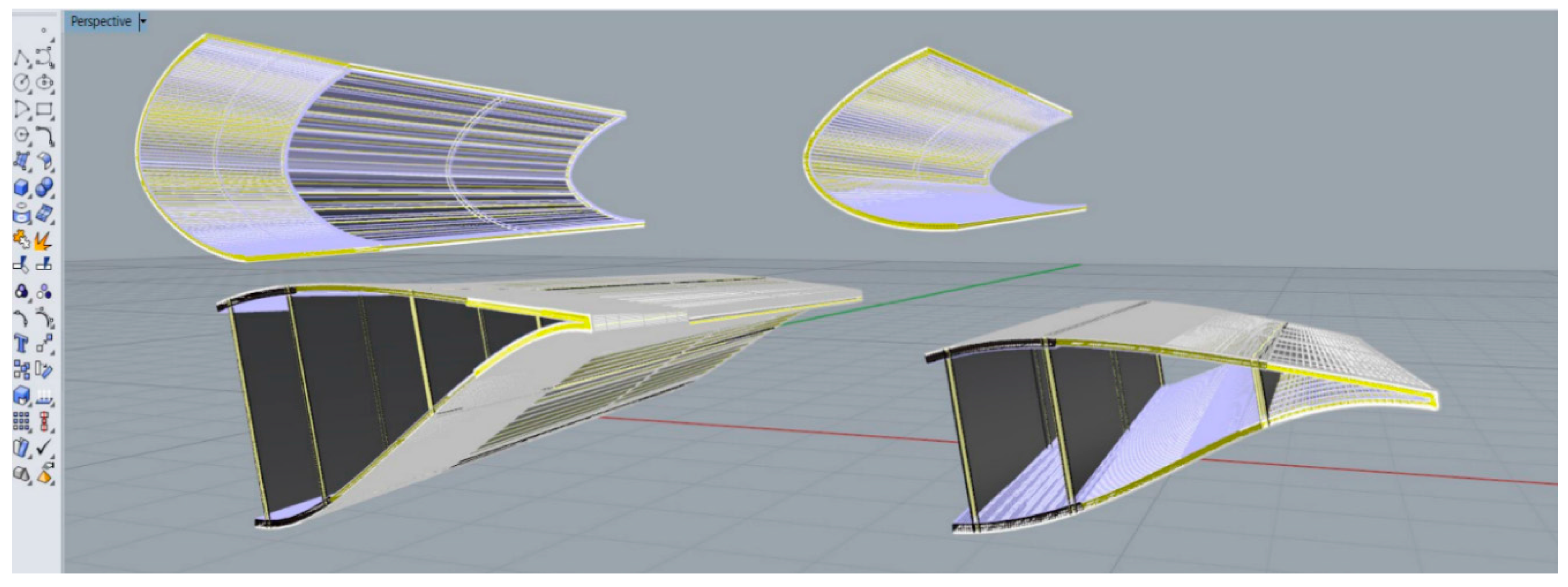
2. Wind Blade Computational Models

A publically available 100 m long prototype wind turbine blade model (SNL-100-01) that was designed by Sandia National Laboratories [12] was used in this study for demonstration purposes. This model, which has not been manufactured, has GFRP in most of the shell/skin structure, and a smaller amount of CFRP in the shear webs and spar caps. The geometry is defined by 25 different airfoil shapes. A total of 393 solid and sandwich composite material lay-ups are used in the blade. The software tool Numerical Manufacturing and Design Tool (NuMAD) [13] was used build the three-dimensional model. Model parameters are the airfoil types, station parameters, division points, composite materials, and shear web division points. Figure 6 shows a finalized version of the SNL-100-01 100 m blade. The different colors in the figure represent the locations of the different materials in the blade. Blades in the 30–50 m length range are typically made of only GFRP. Longer blades (50–80 m) also use some CFRP for increased stiffness. Blade designs are proprietary and wind power companies do not release specific details of their materials and shapes. This study used the Sandia 100 m long glass and carbon blade model as an example. The architectural graphics software Rhino 3D [14] was used to render the blade. Rendering the blade with its actual material thicknesses and real shape is required to extract realistic segments for architectural applications. For structural and aerodynamic modeling only a wireframe finite-element model is typically needed. Figure 7 shows a rendered isometric view of the SNL-100-01 blade.

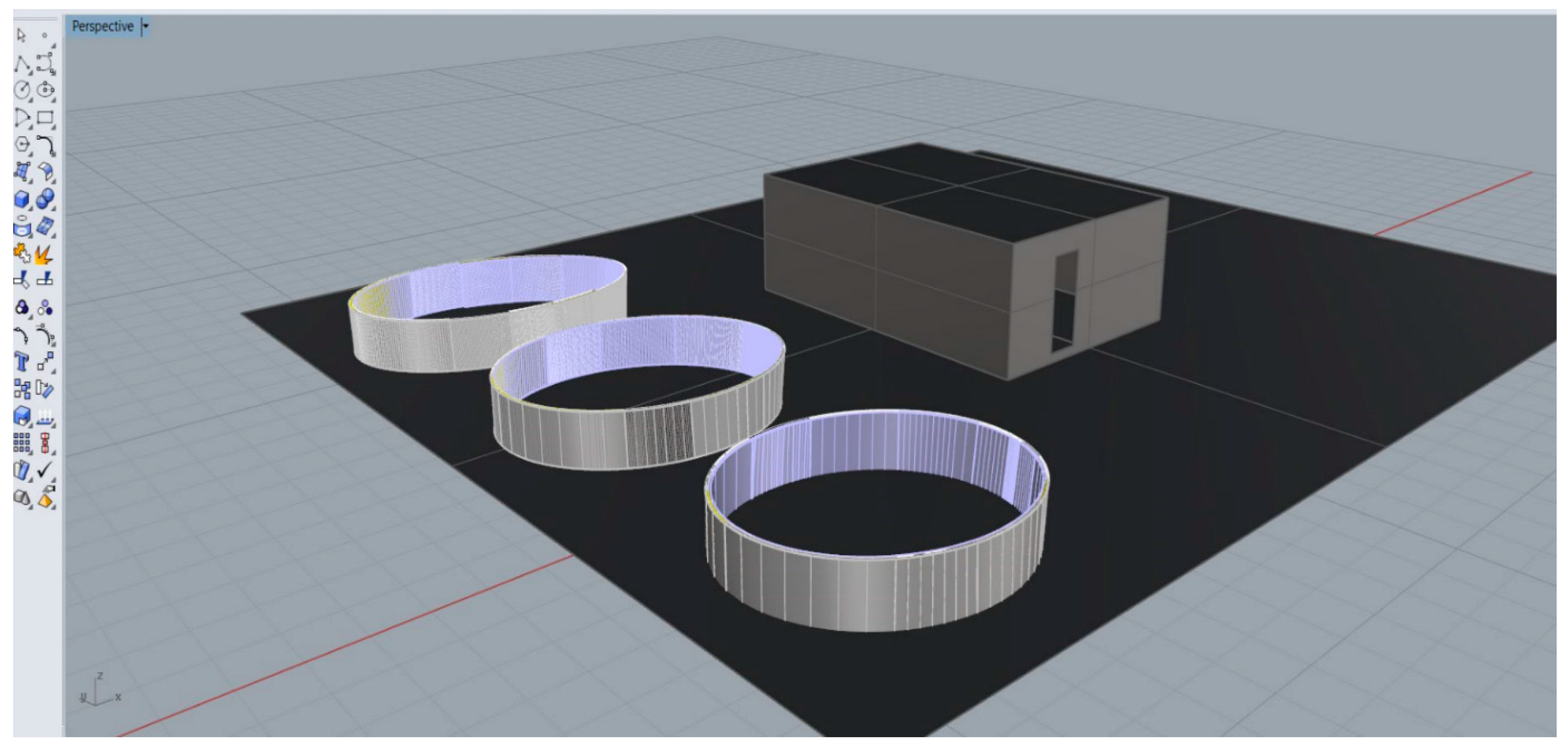
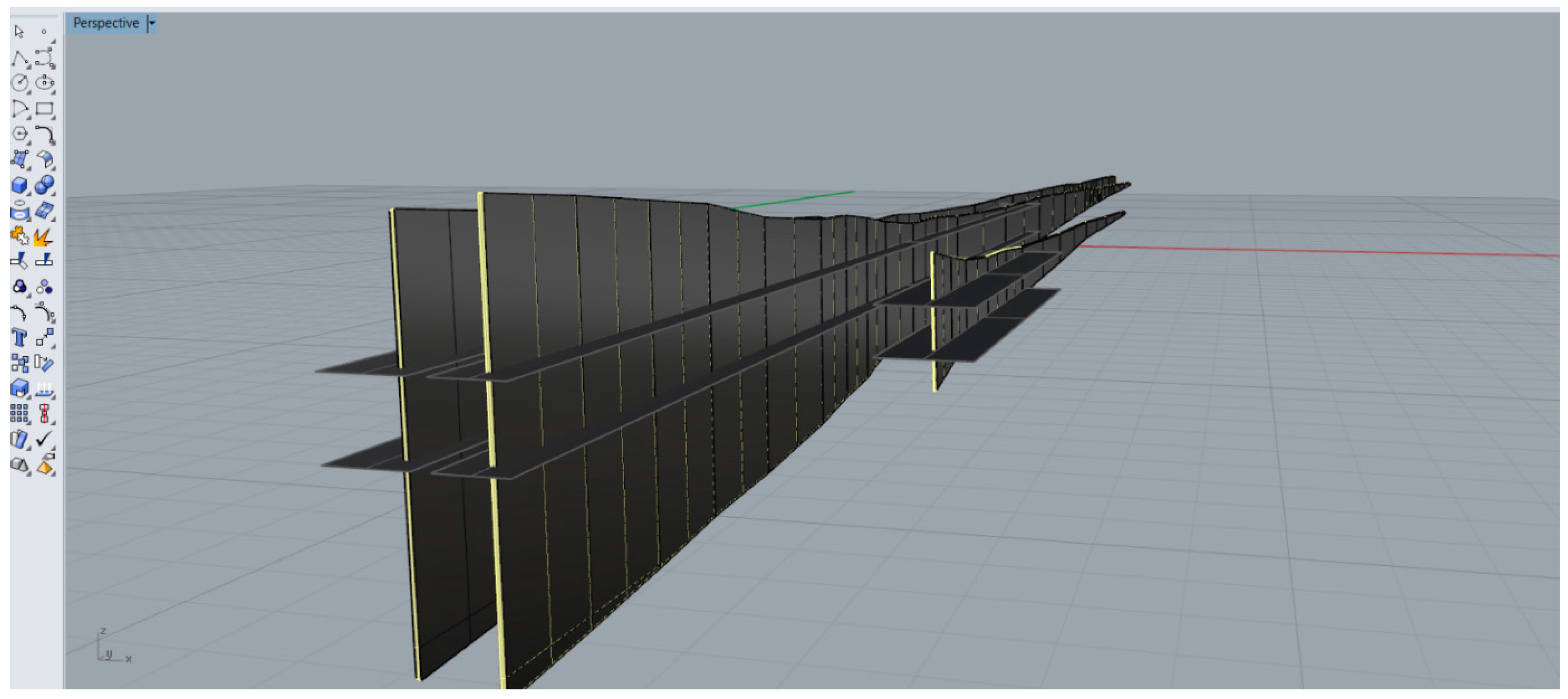
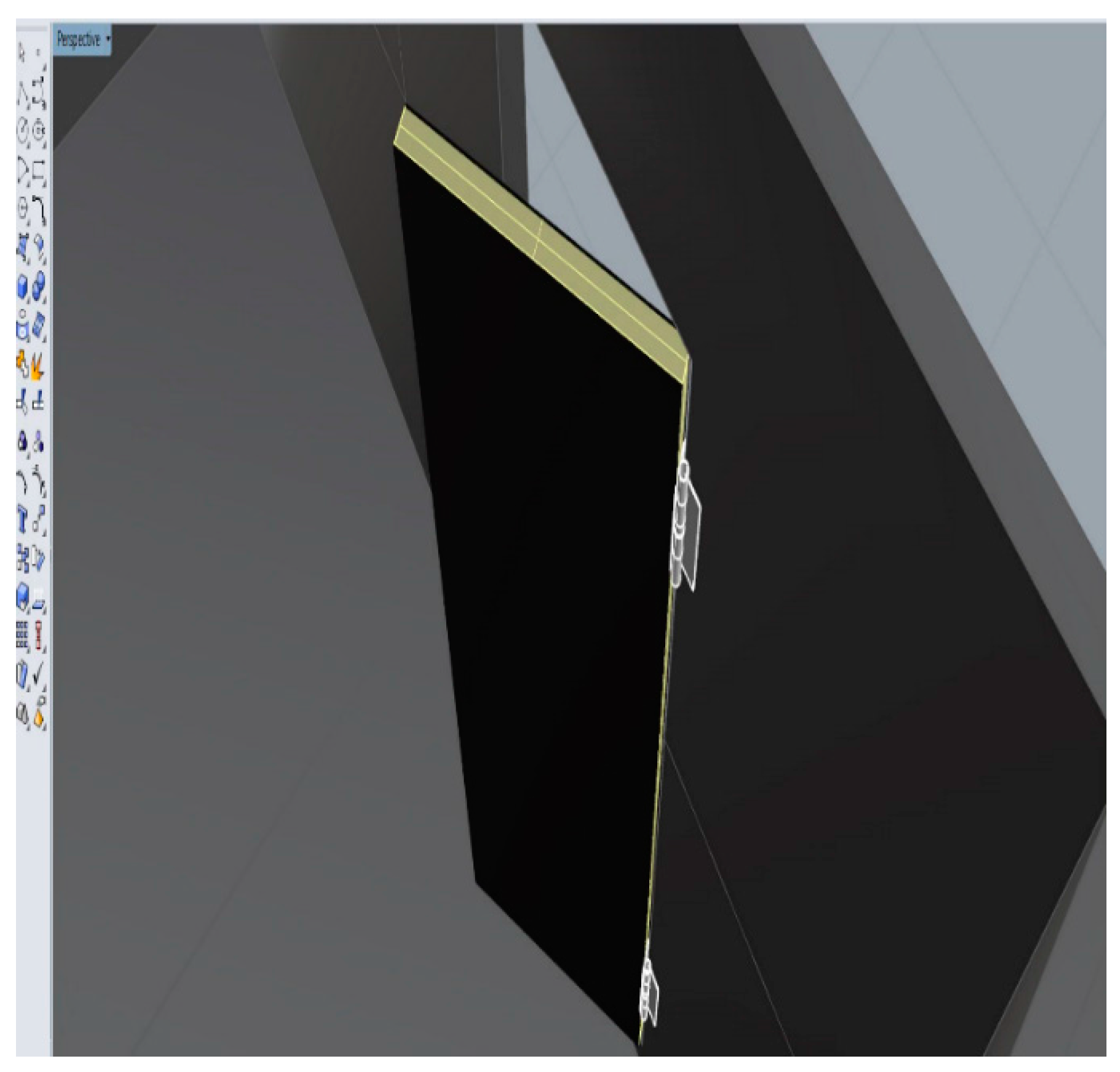
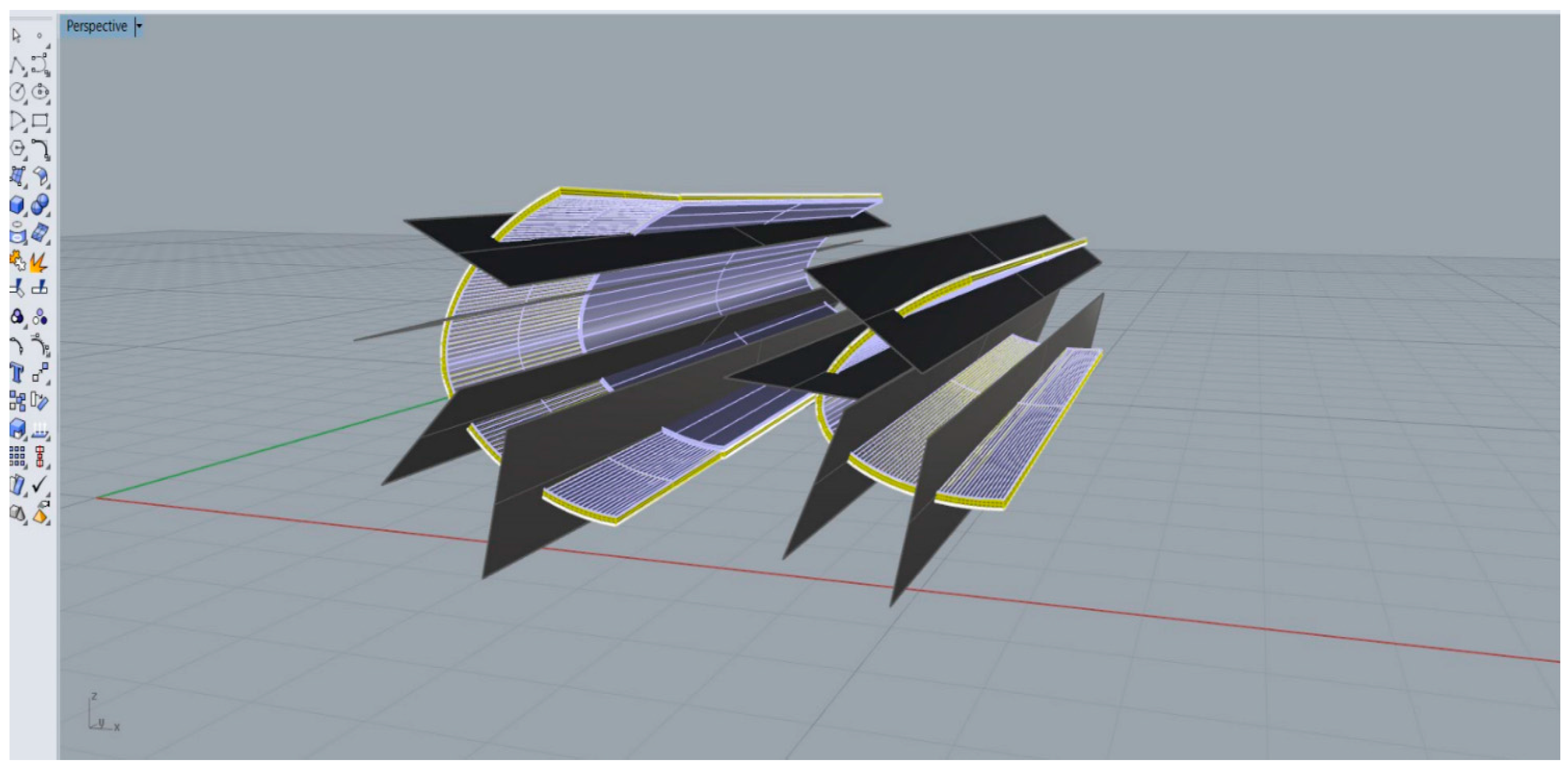
3. Architectural Concepts for Decommissioned 100 m Long Wind Blade Segments

3.1. Root-Foundation System

The root segment of the SNL-100-01 blade has circular and elliptical cross sections. The top and bottom halves of the blade shell consist of a variety of FRP materials arranged in different layers: gelcoat; resin; triaxial fiber fabrics; and unidirectional fiber [12]. At its thickest point, the root has an FRP thickness of 110.6 mm. At its widest point the blade has a chord length (width) of 7.5 m. A typical 2 MW 2000s-era wind blade of about 30–40 m in length would have a maximum chord length of 3 to 4 m.
Based on the Yucatan 2014 surveys [8], flooding is the second most damaging environmental occurrence to informal houses (wind and rain being the first). Elevating homes is proposed to avoid flooding damage. By cutting the wind blade root section (closest to the turbine hub) into short segments, platforms suitable for home elevations can be obtained. The resulting platforms have cylindrical or elliptical cross sections. One meter high platforms of different root sections are shown alongside a rendering of a typical rectangular masonry house with dimensions of 7 m long, 5 m wide, and 2.7 m high are shown in Figure 8. The platforms would have to be driven into the ground. If a higher elevation for a house is desired, larger segmented platforms can be extracted from the root to provide adequate embedment. The inside of the platform may be filled with a rubble. Figure 9 shows houses being elevated off the ground by such platforms (scaled down for the 100 m blade to fit the size of the house).

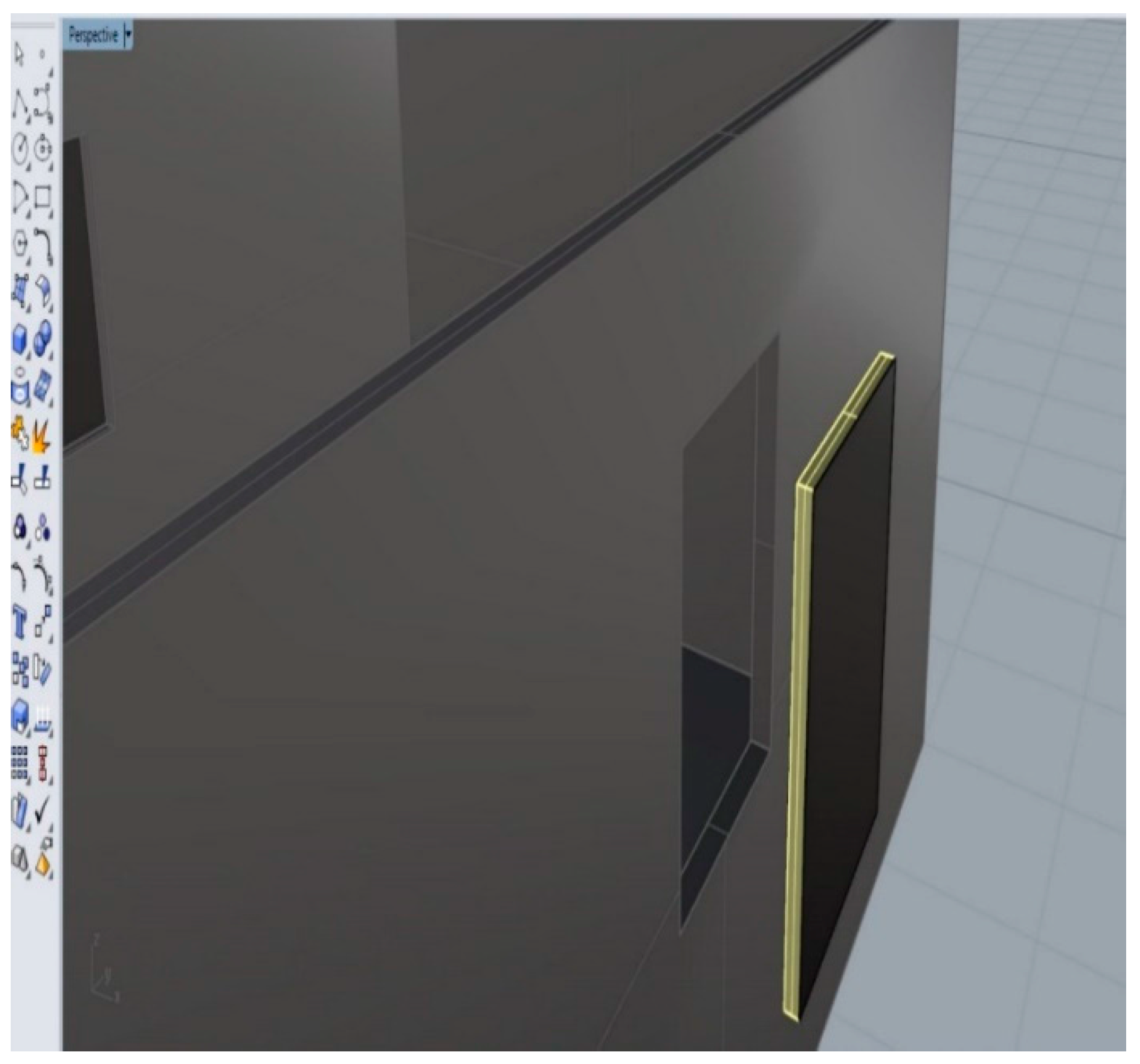
3.2. Doors and Window Covers
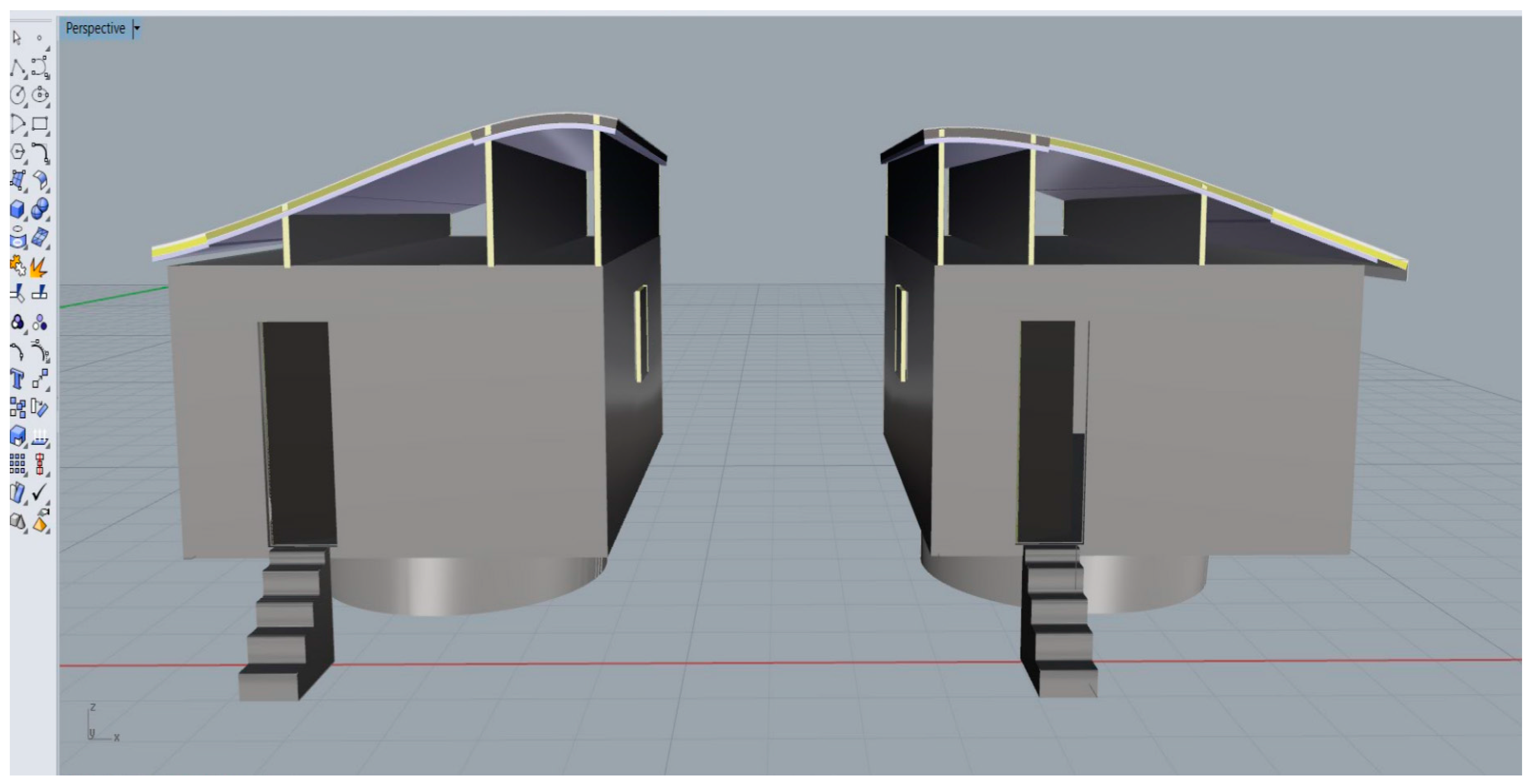
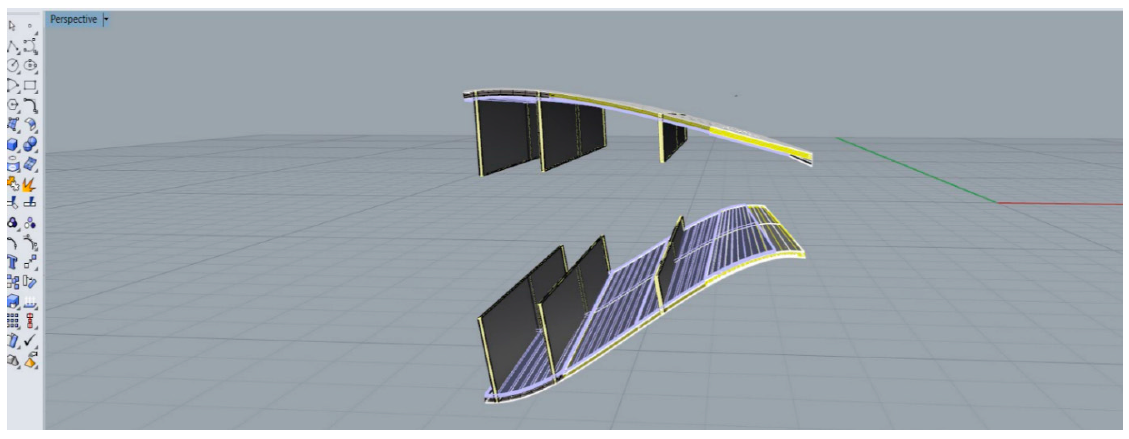
Most door and window fixtures in the informal houses along the Yucatan coast are scavenged and are particularly susceptible to water ingress. Three shear webs connect the top and bottom halves of the blade shell and run along the length of the blade. The shear webs are made of a sandwich composite that has a 60-mm-thick foam core (shown in yellow in Figure 10) in the center and 3-mm CFRP skins (show in black) on either side of the core. Two of the shear webs are 91.9 m long, extending from 2.4 m to 94.3 m, and are connected to the carbon fiber spar caps (which are primarily unidirectional CFRP and provide the flexural stiffness to the blade). The third shear web is 43.8 m long, extending from 16.4 m to 60.2 m and provides extra rigidity to the trailing edge (the flatter edge) in the wide mid-section of the blade. These straight, slender pieces of FRP material are excellent for applications involving doors, window shutters, flooding barriers, structural insulated panels (SIPs), and facades.
Figure 10 shows the three shear webs extracted from the SNL-100-01 wind blade model. Two rectangular virtual cutting planes, one meter apart, are superimposed onto the shear webs. These two planes show the longitudinal cuts that would be needed to produce solid straight one meter high sandwich panels. Figure 11 and Figure 12 show cut-out segments of the shear webs being used as doors and windows covers for the model house, respectively.

3.3. Roof Frames

In Figure 13, the leading-edge (the rounded panels at the front of the blade shell) has been removed from a blade segment to leave the three shear webs and the trailing-edge panels. The leading top and bottom panels have then been separated to make two roof frames. The shear webs (discussed above) run up to 80 m down the blade length, are over 2 m high at their highest point, most importantly, they are straight, making them easy to line up geometrically with other structural elements found in housing construction. To extract the roof frames, the panels must be sliced at an angle so that the cut bisects the shear webs and passes through the joint at the tip of the trailing-edge as seen in Figure 13. Bisecting the blade segment in this manner results in one roof frame from the bottom of the blade and another from the top. These two roof frames are similar, but not identical. Both have the same cross-sectional length, height, and material construction. However, the top roof frame has a concave-down roof curvature, while the bottom roof frame has an inflection point midway along its roof curvature. This geometric difference can be observed in Figure 14, where both half-trusses are displayed next to one another.

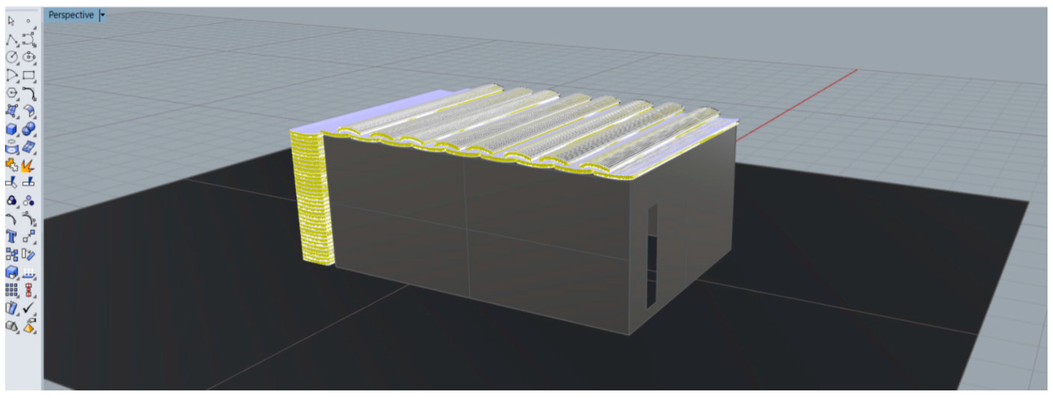
3.4. Interlocking Roof System

The FRP material found in the sandwich panels of the leading-edge of the blade comprises up to a third of the entire wind blade structure. A substantial amount of the FRP material can be salvaged from the leading-edge (rounded front) portion of a decommissioned blade. It is important to understand the geometric arrangement and material composition of the panels if large-sized FRP blade segment are to be extracted and used for architectural/structural applications. Figure 15 shows two blade segments extracted from 30 and 47 m from the root of the blade. Also in Figure 15, the leading edge FRP panels are cut and extracted from the rest of the blade segments. These panels are then reduced down into smaller shells, as shown in Figure 16, where the virtual cuts are represented by the black planes.
Arranging the cut-out segments in a configuration as seen in Figure 17 yields a possible roofing system for affordable housing.
There are two important issues to consider when extracting the leading edge panels and repurposing them for use in this roofing system.
First, there is a slight warping in blade geometry that is due to the twist along the length of the wind blade. The most noticeable effect of this can be observed at the transition between the root and wing segment of the blade. As the blade tapers off, the angle of twist decreases and the warping is less significant. Nonetheless, the extracted leading edge shells will not be perfectly straight, making the interlocking roof configuration difficult to arrange. The gaps formed in between the shell segments may prove to be an issue when providing a leak-proof roofing system. This may be addressed by cutting a small amount of materials off to produce tapered edges (in thickness direction) to make them perfectly fit. An alternative is to seal the gaps due to misfit with other materials.
Second, as the wind blade tapers off after reaching its maximum chord length, the material thickness for the foam decreases. This means that at some points along the blade closer to the root the FRP pieces will be thicker than the pieces found further down the blade. This will raise some concerns when selecting curved segments for the interlocking-roof system. Having segments that are too thin or thick with respect to their adjacent segments will create additional gaps that need filling. However, this would not be an issue if all the concave segments are tapered in one direction and all the convex segments are tapered in the opposite direction.

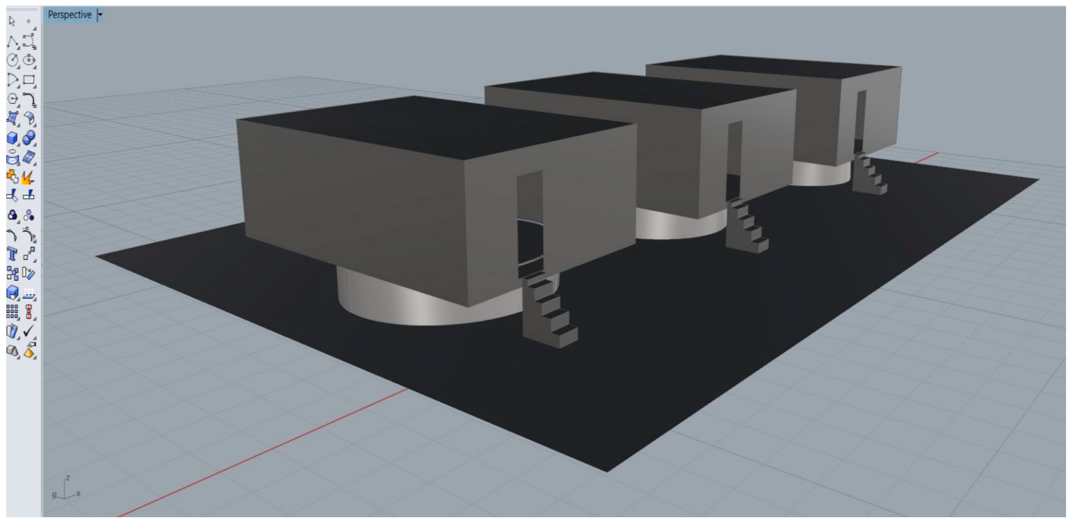
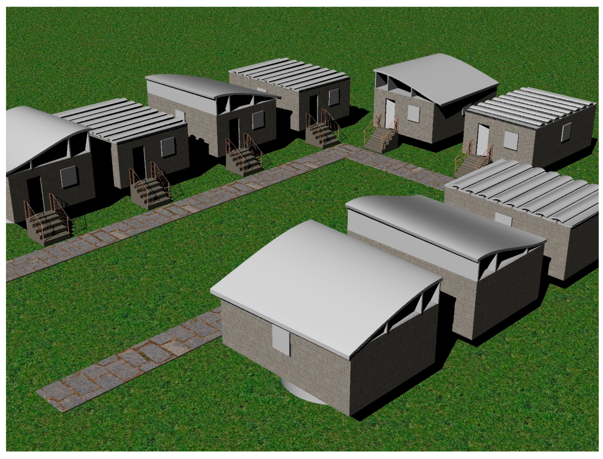
4. A Conceptual Housing Community

Building or retrofitting an affordable housing community with salvaged wind blade parts might resemble something like that depicted in Figure 18. In this representation, the root-foundation system has been used in all the houses, elevating them off the ground. All doors and windows have been modelled using the shear webs panels. Lastly, the roof frame and the interlocking roof configuration are shown in different scenarios.

5. Conclusions

The purpose of this paper was to present a conceptual solution to the impending issue of recycling decommissioned wind turbine blades. As discussed, a wind turbine blade, in this case, the SNL-100-01, can be presented as a wireframe model. From this rudimentary wireframe model, a blade can be reassembled as a 3D model for better architectural/mechanical analysis. Computer software like NuMAD and Rhino 3D made it possible to extract segments from a decommissioned SNL-100-01 wind blade and find real-life structural applications for affordable housing communities. However, this paper is a first step towards making the disposal of wind blades efficient and environmentally friendly. In time, this process of repurposing decommissioned wind blade parts must be further researched with regards to mechanical systems (MEP), structural analysis, logistics, and detailing, other architectural and infrastructural applications; cost and ease of dis- and re-assembly; social accessibility and acceptability.

Acknowledgments

This work was partially supported by NSF grants 1321464 and 1701413, a grant from PowerBridgeNY—New York State Energy Research and Development Authority (NYSERDA) and a grant from the Department for the Economy Northern Ireland under the US-Ireland R&D Partnership Programme (Project No. USI 116). James Biles of CCNY is especially thanked for conducting the housing survey as are the NSF team members Fabio Matta and Ann Johnson (deceased) and the many undergraduate students who participated.

Author Contributions

L.C.B., F.R.A. and T.A.-H. proposed the different housing design concepts; L.C.B. provided data on the Mexican context; F.R.A. built the NuMAD and Rhino models; J.-F.C., R.M. and A.Y. provided input on structural, architectural and materials, respectively. L.C.B. and F.R.A. wrote the paper.

Conflicts of Interest

The authors declare no conflict of interest. The funding sponsors had no role in the design of the study; in the collection, analyses, or interpretation of data; in the writing of the manuscript, and in the decision to publish the results.

References

  1. Arias, F.R. Assessment of Present/Future Decommissioned Wind Blade Fiber-Reinforced Composite Material in the United States; Internal Research Report; Department of Civil Engineering, City College of New York: New York, NY, USA, 2016. [Google Scholar] [CrossRef]
  2. Albers, H.; Greiner, S.; Seifert, H.; Kühne, U. Recycling of Wind Turbine Rotor Blades—Fact or Fiction? (Recycling von Rotorblättern aus Windenergieanlagen—Fakt oder Fiktion?). DEWI Mag. 2009, 34, 32–41. [Google Scholar]
  3. Welstead, J.; Hirst, R.; Keogh, D.; Robb, G.; Bainsfair, R. Research and Guidance on Restoration and Decommissioning of Onshore Wind Farms. Scottish Natural Heritage Commissioned Report No. 591. 2013. Available online: http://www.snh.org.uk/pdfs/publications/commissioned_reports/591.pdf (accessed on 16 January 2018).
  4. Liu, P.; Barlow, C.Y. Wind turbine blade waste in 2050. Waste Manag. 2017, 62, 229–240. [Google Scholar] [CrossRef] [PubMed]
  5. GWEC (Global Wind Energy Council). Global Wind Report—Annual Market Update 2016; Global Wind Energy Council: Brussels, Belgium, 2016; Available online: http://gwec.net/publications/global-wind-report-2/global-wind-report-2016/ (accessed on 16 January 2018).
  6. GWEC (Global Wind Energy Council). Global Wind Energy Outlook 2016; Global Wind Energy Council: Brussels, Belgium, 2017; Available online: http://gwec.net/publications/global-wind-energy-outlook/global-wind-energy-outlook-2016/ (accessed on 16 January 2018).
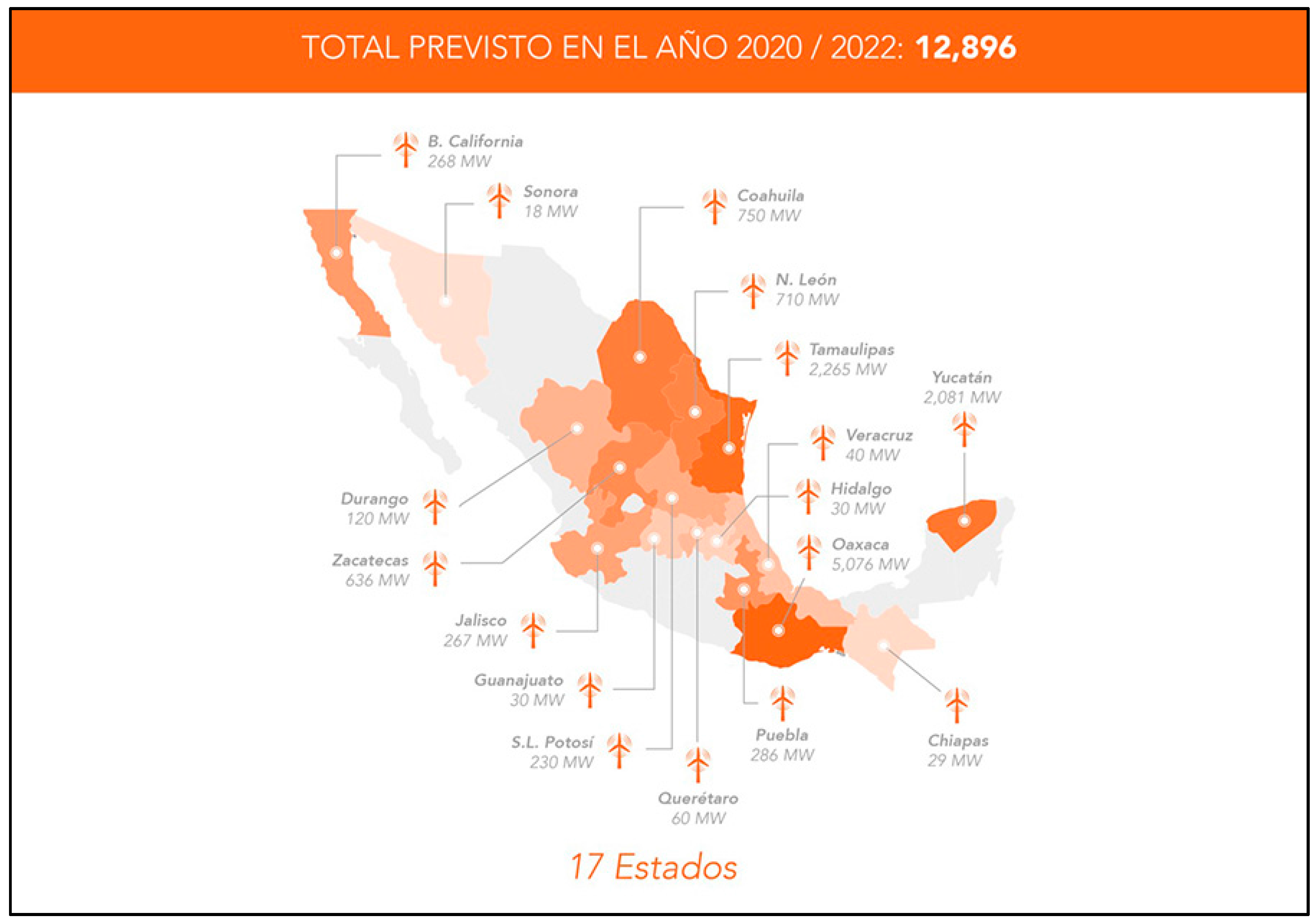
  7. AMDEE, Asociación Mexicana de Energía Eólica (Mexican Wind Power Association). Estimated Wind Energy Capacity in Mexico 2020; Mexican Wind Power Association (AMDEE): Mexico City, Mexico, 2017; Available online: http://www.amdee.org/mapas/parques-eolicos-mexico-2020 (accessed on 16 January 2018).
  8. Bresko, M.; Cuéllar-Azcárate, M.; Matta, F.; Bank, L.C.; Biles, J.J.; Johnson, A. Overcoming Barriers to Diffusion and Adoption of Sustainable and Resilient Building Materials in Coastal Areas of Southern Mexico—Analysis of 2014 Household Survey Data; Internal Research Report; University of South Carolina: Columbia, SC, USA, 2017. [Google Scholar] [CrossRef]
  9. Ortegon, K.; Nies, L.; Sutherland, J. Preparing for end of service life of wind turbines. J. Clean. Prod. 2013, 39, 191–199. [Google Scholar] [CrossRef]
  10. Oliveux, G.; Dandy, L.; Leeke, G. Current status of recycling of fibre reinforced polymers: Review of technologies, reuse and resulting properties. Prog. Mater. Sci. 2015, 72, 61–99. [Google Scholar] [CrossRef]
  11. Job, S.; Leeke, G.; Mativenga, P.T.; Oliveux, G.; Pickering, S.; Shuaib, N.A. Composites Recycling: Where Are We Now? Composites UK Ltd.: Berkhamsted, UK, 2016. Available online: https://compositesuk.co.uk/system/files/documents/Recycling%20Report%202016.pdf (accessed on 16 January 2018).
  12. Griffith, T. The SNL100-01 Blade: Carbon Design Studies for the Sandia 100-Meter Blade; SAND2013-1178; Sandia National Laboratories: Albuquerque, NM, USA, 2013. Available online: http://prod.sandia.gov/techlib/access-control.cgi/2013/131178.pdf (accessed on 16 January 2018).
  13. Berg, J.C.; Resor, B.R. Numerical Manufacturing and Design Tool (NuMAD v2.0) for Wind Turbine Blades: User’s Guide; SAND2012-7028; Sandia National Laboratories: Albuquerque, NM, USA, 2012. Available online: http://energy.sandia.gov/energy/renewable-energy/wind-power/rotor-innovation/numerical-manufacturing-and-design-tool-numad/ (accessed on 16 January 2018).
  14. Robert McNeel & Associates. Rhino 3D. Rhinoceros 3D; Robert McNeel & Associates: Seattle, WA, USA, 2017; Available online: www.rhino3d.com (accessed on 16 January 2018).
Figure 1. Global Cumulative Capacity [5].
Recycling 03 00003 g001
Figure 2. Global Wind Energy Predictions [6].
Recycling 03 00003 g002
Figure 3. Mexico 2020 Forecast [7].
Recycling 03 00003 g003
Figure 4. Typical confined concrete masonry construction in Yucatan communities (photo: L. Bank).
Recycling 03 00003 g004
Figure 5. Interior of house showing moisture damage (Photo: J. Biles).
Recycling 03 00003 g005
Figure 6. The SNL-100-01 NuMAD Blade Model [2].
Recycling 03 00003 g006
Figure 7. The SNL-100-01 blade Rendered in Rhino 3D.
Recycling 03 00003 g007
Figure 8. Root Sections alongside house model.
Recycling 03 00003 g008
Figure 9. Houses Elevated on Blade Sections from the Root.
Recycling 03 00003 g009
Figure 10. Extracted Shear Webs with Horizontal Cutting Planes.
Recycling 03 00003 g010
Figure 11. Shear Web—Door.
Recycling 03 00003 g011
Figure 12. Shear Web—Window Cover.
Recycling 03 00003 g012
Figure 13. Blade Segment Cut.
Recycling 03 00003 g013
Figure 14. Roof Frames.
Recycling 03 00003 g014
Figure 15. Separated Leading Edge (Top) and Trailing Edge Segments (Bottom).
Recycling 03 00003 g015
Figure 16. Leading Edge Virtual Cutting planes.
Recycling 03 00003 g016
Figure 17. Interlocking Roof Panel Configuration.
Recycling 03 00003 g017
Figure 18. Conceptual Housing Community.
Recycling 03 00003 g018

