Article

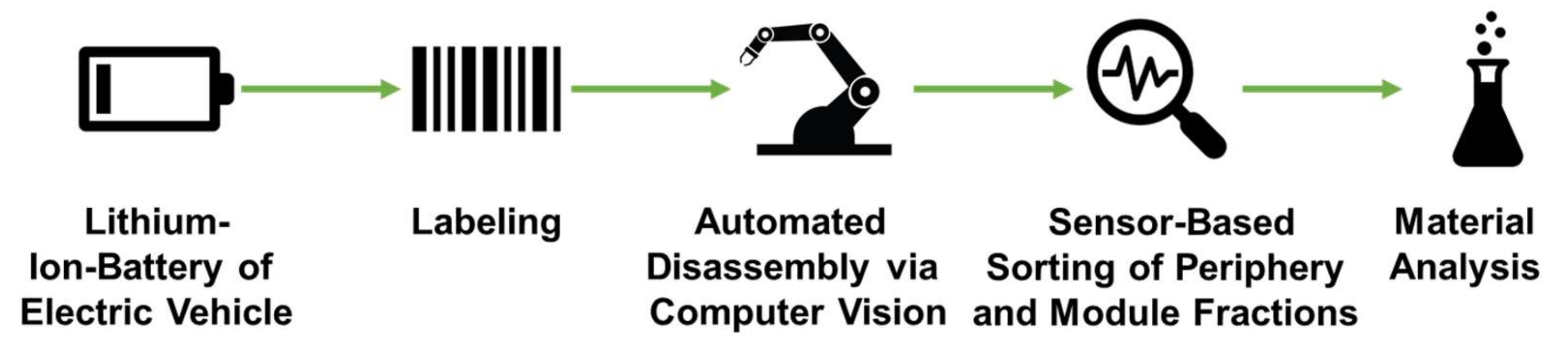
An Approach for Automated Disassembly of Lithium-Ion Battery Packs and High-Quality Recycling Using Computer Vision, Labeling, and Material Characterization

1
IWARU Institute for Infrastructure, Water Management, Resources and Environment, University of Applied Sciences Münster, Corrensstraße 25, 48149 Münster, Germany
2
Institute for Business Cybernetics e.V. (IfU), Dennewartstraße 27, 52068 Aachen, Germany
3
Chair for Production Engineering of E-Mobility Components, RWTH Aachen University, Bohr 12, 52072 Aachen, Germany
4
Department of Process Metallurgy and Metal Recycling (IME), RWTH Aachen University, Intzestraße 3, 52056 Aachen, Germany
*
Author to whom correspondence should be addressed.
Recycling 2022, 7(4), 48; https://doi.org/10.3390/recycling7040048
Submission received: 29 April 2022 / Revised: 5 July 2022 / Accepted: 13 July 2022 / Published: 20 July 2022

Abstract

:
A large number of battery pack returns from electric vehicles (EV) is expected for the next years, which requires economically efficient disassembly capacities. This cannot be met through purely manual processing and, therefore, needs to be automated. The variance of different battery pack designs in terms of (non-) solvable fitting technology and superstructures complicate this. In order to realize an automated disassembly, a computer vision pipeline is proposed. The approach of instance segmentation and point cloud registration is applied and validated within a demonstrator grasping busbars from the battery pack. To improve the sorting of the battery pack components to achieve high-quality recycling after the disassembly, a labeling system containing the relevant data (e.g., cathode chemistry) about the battery pack is proposed. In addition, the use of sensor-based sorting technologies for peripheral components of the battery pack is evaluated. For this purpose, components such as battery pack and module housings of multiple manufacturers were investigated for their variation in material composition. At the current stage, these components are usually produced as composites, so that, for a high-quality recycling, a pre-treatment may be necessary.

1. Introduction

As part of the European “Green Deal”, the EU member states are committed to becoming climate-neutral by 2050. One sector with a high potential for reducing emissions is the transport sector, among others, which is why alternative drive systems such as electric vehicles (EV) that are powered by electricity from renewable energies, are increasingly coming into focus. In Germany alone, around 7–10 million EVs are expected to be used by 2030 in order to achieve the climate targets [1], which will result in an increasing volume of end-of-life batteries in the future. Lithium-ion batteries are a key technology for electric vehicles. In the lifetime of an electric vehicle, the battery is usually expected to be replaced; therefore, resource-saving and efficient recycling of the lithium-ion battery cells is required. This is complicated by their heterogeneity, which is mainly due to the complexity and design diversity of the battery packs and a variety of possible cathode materials, such as nickel-manganese-cobalt (NMC) or lithium-iron-phosphate (LFP) of the battery cells.
Currently, disassembly is usually done manually and is not non-destructive. Moreover, the lack of labeling for the materials that are used hinders high-quality recycling. The DemoSens project, therefore, aims to develop an appropriate label and automated disassembly (see Figure 1) using machine learning methods. Considering the diversity and non-existing data on battery pack construction, the goal is to develop a flexible and adaptable approach to enable economical recycling. In addition, the use of sensor-based sorting of the disassembled fractions such as busbars and housing as well as the coarse fraction from the crushing and sieving of modules is being tested. This issue presents, besides the legal framework, the process of the manual disassembly steps. Challenges regarding the automation of the disassembly process are derived from this. Based on the selected tools, such as suitable sensors for material detection and the procedure for digitalization and automation is described. In addition, a labeling system is presented to support the disassembly and separation of the disassembled battery components for recycling by type. First, the results regarding the so-called instance segmentation and pose matching for the guidance of the robot along with first sensor-based material detection are shown.

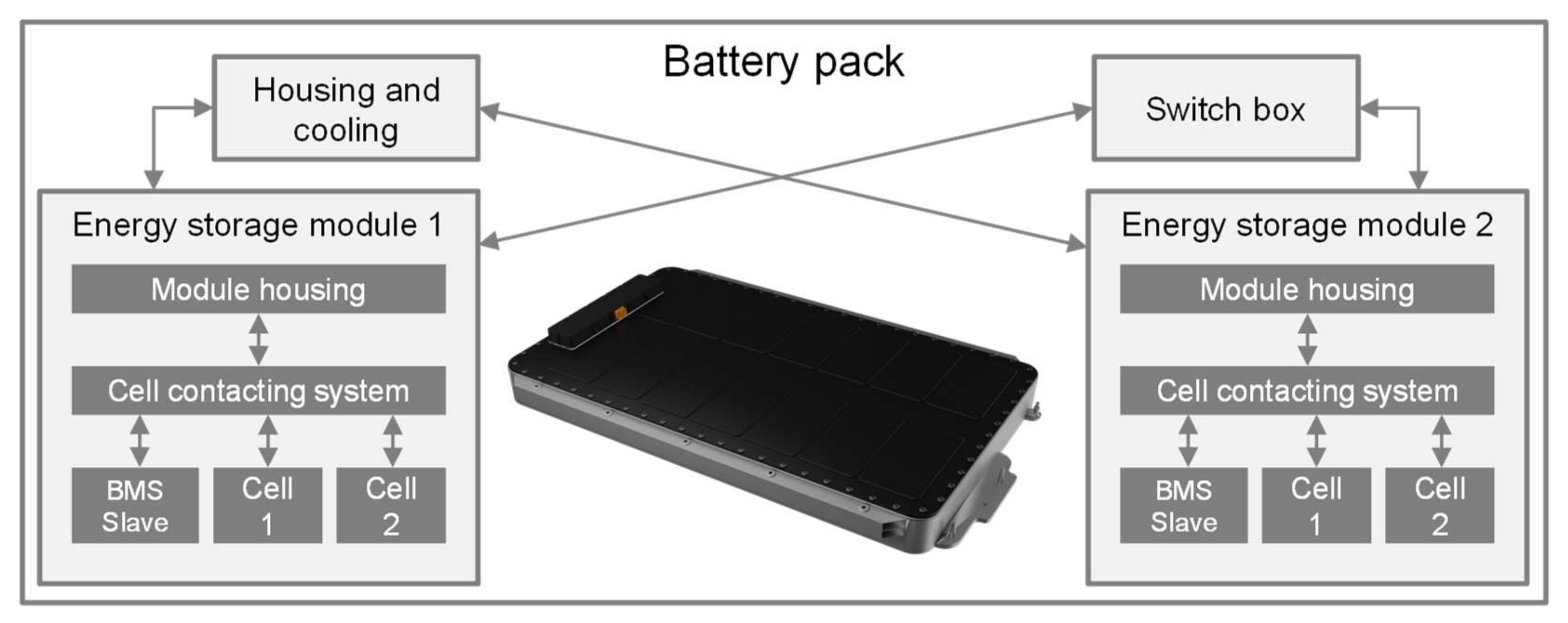
2. Procedure in the Disassembly of Battery Packs

The following section shows the legal framework in the recycling of lithium-ion-batteries. Furthermore, the process of disassembly and disposal of battery fractions is presented. Based on this, the challenges for the digitization and automation of the disassembly process are evaluated.

2.1. Legal Framework

As part of the European Commission’s European Green Deal, an amendment to the currently valid Battery Directive [2] was proposed in the form of the Battery Regulation [3]. The main objectives of this regulation are to standardize regulations in the EU, to promote the circular economy and to reduce the environmental and social impacts at all stages of a battery’s life cycle. These goals should be achieved by different actions; for traction batteries the following measures are proposed:
  • Specification of the carbon footprint of the manufacturing process
  • Specification of the recyclate use from 2027 and from 2030 onwards
  • Information on the durability and performance
  • Easy removal and replacement of batteries from devices at the end-of-life
  • Increasing the recycling efficiencies for lithium-ion batteries of 65% (from 2025) and 70% (from 2030) and material recovery rates for individual battery components (e.g., lithium, 70% from 2026 [4])
  • Battery passport to provide basic information about the battery
The battery passport shall also provide information on battery dismantling and composition including cathode chemistry for recycling companies. In addition, an adaptation of Regulation 493/2012 to technical advances and industrial recycling processes is planned. The extent to which the battery regulation proposal will be implemented cannot be estimated at this time. However, the proposal for an EU Battery Regulation was adopted by the Environment Committee of the EU Parliament.

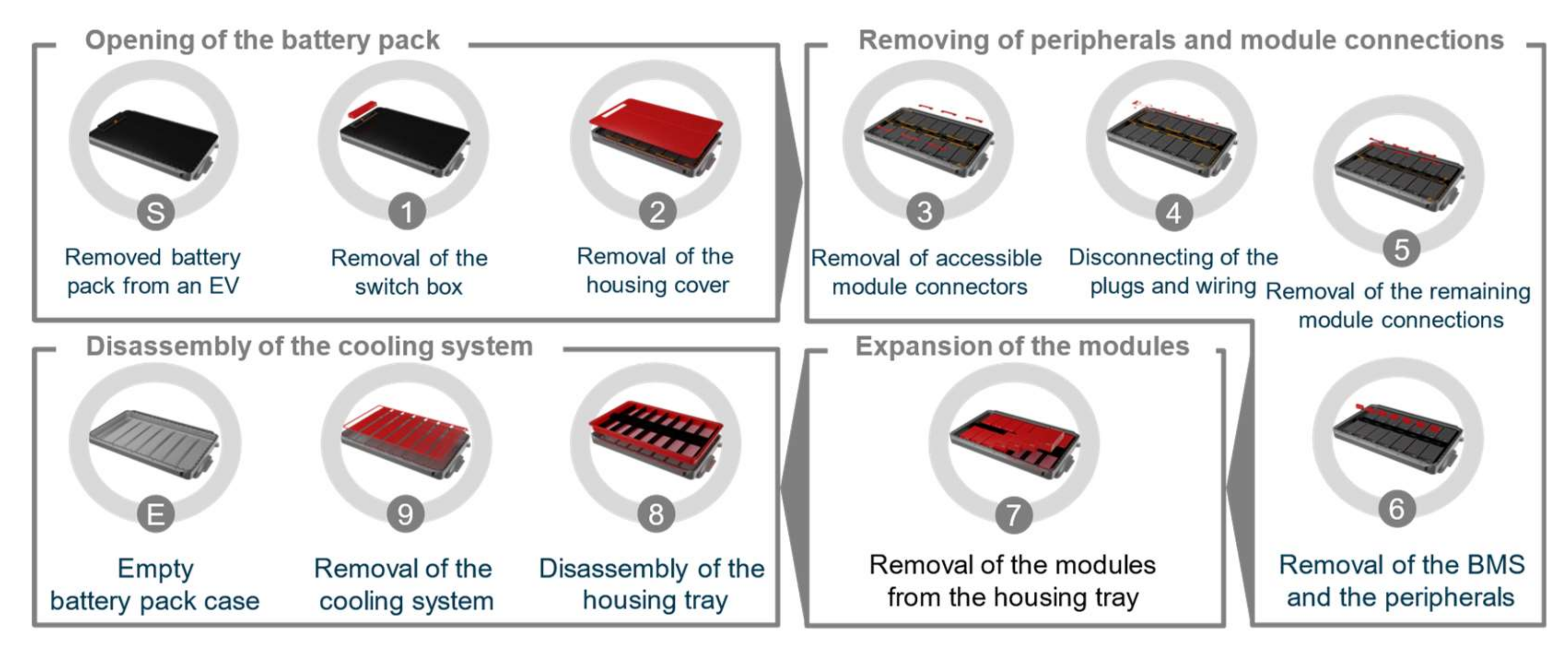
2.2. Disassembly Process of Lithium-Ion Traction Batteries

The disassembly of lithium-ion traction batteries after reaching their end-of-life (EoL) represents a promising approach to maximize the purity of the segregated material [5]. The research topic of disassembly is, therefore, also increasingly addressed in research in terms of the number of scientific publications [6].
The basic structure of a battery pack for EVs consists of a modular product architecture and is shown in Figure 2.
Several individual battery cells are combined into a battery module by serial and/or parallel electrical interconnection and mechanical joining. These battery modules are connected at the next higher system level by an electrical interconnection and mechanical joining to form a battery pack. Normally, the cooling system for keeping the battery cells at the right temperature during operation and the switch box with the battery management system (BMS) are also located within a battery pack [8].
The investigation of traction batteries at the current stage has shown that, due to the product design, disassembly can only be feasibly carried out from the battery pack level down to the battery module level [9]. Within research activities, however, the possibilities of dismantling the battery system down to the cell level are also being scientifically investigated [9,10].
In contrast to dismantling, which is aimed at the rapid irreversible separation of components, disassembly involves the separation of components in such a way that they could potentially be reassembled. The majority of the current recycling processes, such as Umicore, Retriev Technologies, or Accurec, involve the dismantling of battery packs to varying depths (e.g., module level, cell level) as part of a pre-processing step. The LithoRec process also provides for manual disassembly activities that go beyond the classic dismantling scope to disassemble the battery pack housing, the battery management system (BMS), the wiring harness, and the cooling system before the separated battery modules are passed on to the next stage of the recycling process [11].
The multitude of different product designs from different manufacturers on the market makes it difficult to define a generally valid disassembly process for lithium-ion traction batteries [12]. Nevertheless, quasi-universal superordinate disassembly process steps can be defined due to the related product architecture. Figure 3 shows the sequence of the higher-level disassembly process steps for a typical battery pack.
The sequential order of the individual process steps and the subordinate partial disassembly tasks can vary depending on the system design [13,14,15].
In most system concepts, such as that of the Audi e-tron 50, the battery pack cover has to first be removed before the electrochemical state of the battery pack can be determined and the system deep discharged. This is due to the fact that the manufacturers do not provide the communication protocols to read out the BMS and thus also close the contactors to discharge the battery without opening the housing cover. After opening the battery pack, the next process steps are to remove the electrical module connectors as well as the wiring harness and the BMS components. After the battery modules have been removed, the battery pack housing is dismantled, if possible, and the cooling system is removed.
After pre-separation by means of disassembly or dismantling, the individual component fractions are fed into the downstream recycling steps. Pure fractions (provided that the type of material is known), such as the battery system housing, can be fed directly into the corresponding classic recycling processes, e.g., screws in scrap recycling, or busbars and electronic components in e-scrap processing plant [16]. The battery modules, on the other hand, are further processed within mechanical comminution processes, hydrometallurgical, or pyrometallurgical processes, depending on the respective recycling process [17].

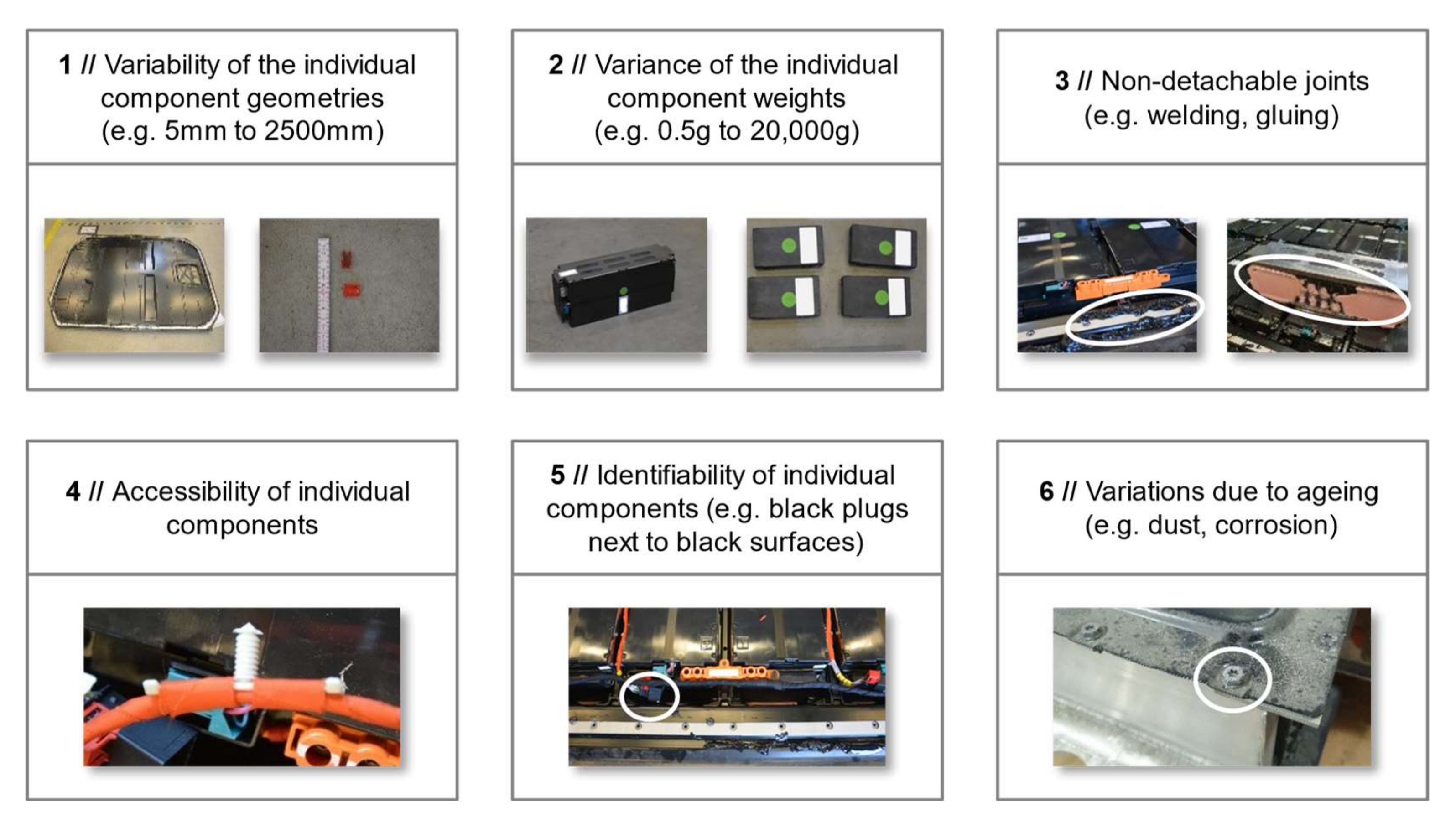
2.3. Challenges in Automating the Lithium-Ion Traction Battery Disassembly Process

At the current stage, both the disassembly and dismantling activities are mainly carried out manually [18]. In addition to the still comparatively small quantities of battery pack returns to be recycled at the current point in time, there are a number of technological challenges with regard to full sensor-based component detection and automation of the battery pack disassembly process. Figure 4 provides an overview of common challenges for process automation, which result directly from the product design of state of the art battery systems.
The variability of individual component geometries within a battery pack, as well as the increased complexity across different battery pack designs, is a key challenge for automating the disassembly process. In addition, the high variance in the weights of the components to be disassembled poses a difficulty for the requirement-oriented and efficient selection of the necessary disassembling tools and robot platforms. Another main challenge is posed by non-detachable connections (e.g., glued or welded connections), such as the thermal interface materials for the thermal coupling of the battery cells to the cooling plate or the adhesive seal between the housing cover and housing tray. Special tools and processes have to be developed for this in order to be able to automate the separation process. The difficult accessibility of the individual components also adds complexity to the elaboration of an automation concept [19,20].
Another challenge for automation is the ageing of the external components, especially those that are exposed to the weather, such as the screws outside the battery housing. Here, the effects of corrosion as well as dust and dirt deposits can make it impossible to detect their position or loosen those using conventional methods.
For the sensor-based detection of components by means of color and depth data, in addition to the poor accessibility of individual components, the lack of identifiability due to almost identical color or no clear geometric separation is a major challenge (see Figure 4).
Nevertheless, there is an urgent need for an automated disassembly solution to sufficiently address these technological challenges. In particular, the technological challenges must be addressed by dimensioning the disassembly system solution to meet the requirements and by developing special disassembly tools and component detection methods. The foreseeable strongly increasing registration numbers of electric vehicles lead to returns of a similar magnitude after the battery systems reach their EoL. This puts into focus the need for process automation, to ensure an economical separation process in the future. There are already approaches in research to (partially) automate individual steps in the disassembly of battery systems [9,10,12,21]. However, these approaches do not yet provide a holistic solution for overcoming the existing technological challenges [19].

3. Methodical Approach for an Automated Disassembly and Intelligent Sorting Process

The following section presents the necessary applications for automated disassembly and automated material recognition. The application of a labeling system is also considered, which could provide information about the battery and the process.

3.1. Framework Approach and Tools for a Digitization of the Process

The central components of the automated disassembly comprise of the automated detection and pose estimation of components. Based on this, the derivation of goal positions of the robot end effector (EEF) for disassembly operations, such as grasping of a component or loosening of a screw, is achieved.
This is realized by utilizing a depth camera and processing the 3D point cloud from RGB + depth observations of the scene using various vision algorithms to determine the exact position and orientation of a component. The image processing steps that are involved from image capture to derivation of the final 6D pose estimate of a component are depicted in Figure 5.
The camera provides the 3D RGB point cloud and first only the RGB information is extracted and fed into an instance segmentation network. The outputs of the network are the detected instances of the respective component with the according mask - meaning pixel-wise classification. This way, the component is already localized. However, the exact pose remains unknown, which is relevant to determine the correct EEF position for e.g., grasping of the component. Therefore, the resulting mask is used to extract the relevant points from the point cloud. Then, this extracted scene point cloud of the component is matched with a previously created model point cloud of the component which lies in a known coordinate system. This is achieved using so-called point cloud registration algorithms which, in this case, deliver the transformation matrix from the model point cloud to the scene point cloud. Thereby, the full 6D pose – position (x, y, z) and orientation (roll, pitch, yaw) – of the component in the scenery can be obtained and from here the correct robot pose can be derived.
The individual steps of image capture, instance segmentation, and point cloud registration are described in more detail below.

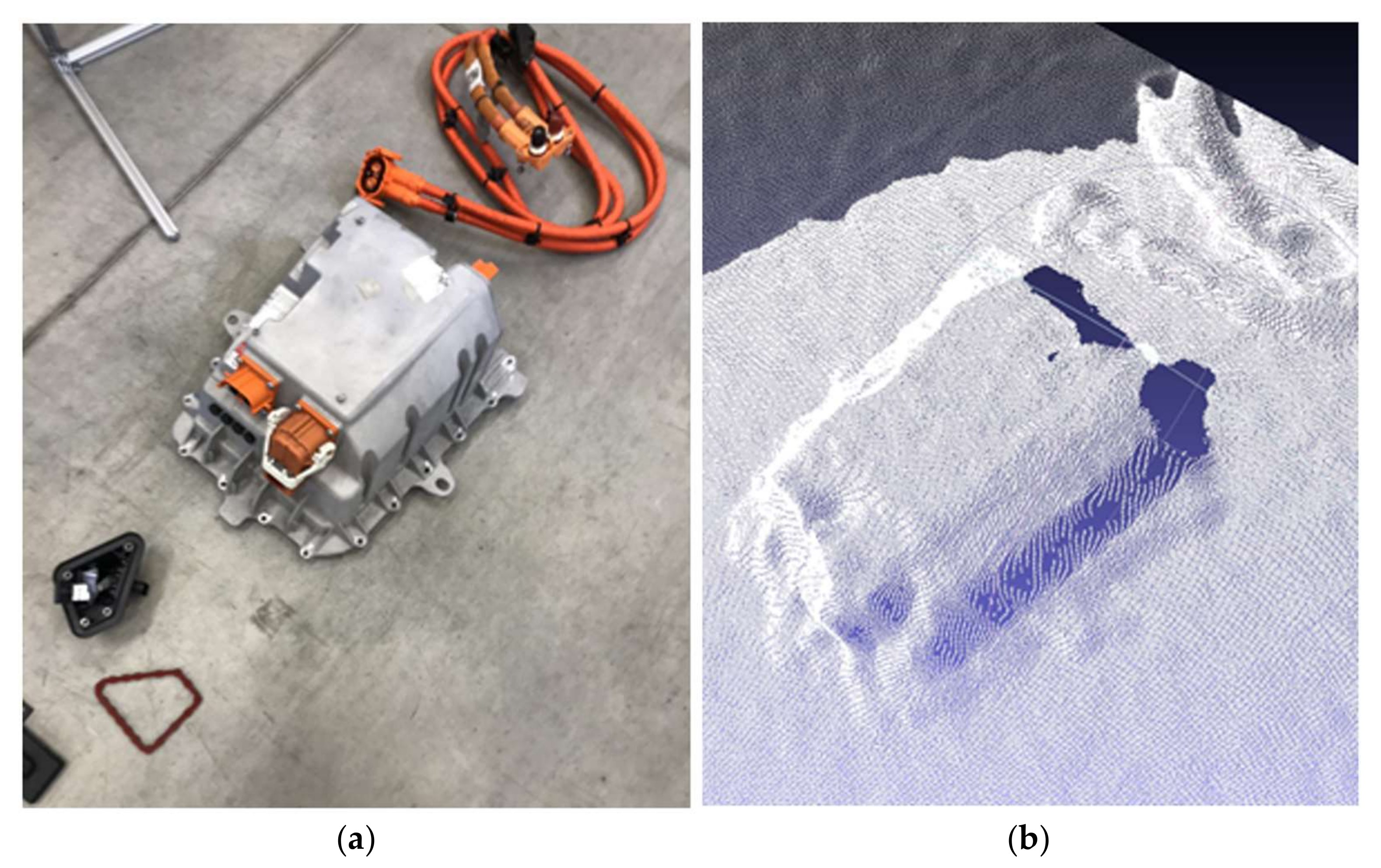
3.1.1. Image Capture: Depth Sensor Selection

This section deals with the selection of a suitable camera system. Besides larger components, smaller components also have to be detected accurately. Therefore, a suitable depth sensor is necessary in order to acquire high resolution depth data to derive precise grasp pose determination for the robotic system. Despite the prominence of low-cost hardware in the field of robotics, higher-quality sensor technology is required for this use case which is illustrated in Figure 6. Here, an exemplary image capture of the switch box and the according point cloud that was observed by the Realsense D435i is depicted.
It can be seen that the geometry is only roughly reproduced in the point cloud. Considering the point cloud registration step that is depicted in Figure 5, this is not sufficient in accuracy, especially for even smaller components such as the busbars or plugs. Therefore, a high resolution depth camera—the Zivid Two [22]—was chosen. This camera has the following specifications:
  • Structured Light: The camera has a projector and a 2D camera (see Figure 7). The projector sends light patterns onto the scene, while the camera captures the distortion of this pattern that is created by the underlying geometry. Based on this, the point cloud is calculated.
  • Output: High resolution 3D RGB point cloud → in comparison many high resolution point clouds of other camera models do not inhibit RGB information
  • Increased robustness against reflections
  • Lightweight (mounting on robot)
  • Advanced hand-eye-calibration-API (mounting on robot)
In addition to the above-mentioned properties and advantages of the camera system, however, the disadvantages that are described below have also be taken into account:
  • No translucent objects
  • Depth image acquisition only in stationary mode, i.e., the camera must be motionless (on-the-fly data acquisition not possible)
  • Limited use with highly reflective surfaces
  • Should not be used outside or with direct light incidence
The drawbacks are manageable regarding the disassembly of a battery as the procedure takes place inside an industrial setting with defined light conditions, there are no translucent objects that are present in the battery, both the battery and the robot can remain stationary for the duration of an image acquisition, and possible moderate reflections can be compensated by suitable camera settings.
In Figure 8a, an exemplary point cloud of the switch box that was produced by the Zivid Two is depicted for visualization purposes without RGB information. In (b), the point cloud of delicate and small components such as busbars are shown. This level of accuracy allows for point cloud registration algorithms as depicted in Figure 5 even for these small and delicate components.

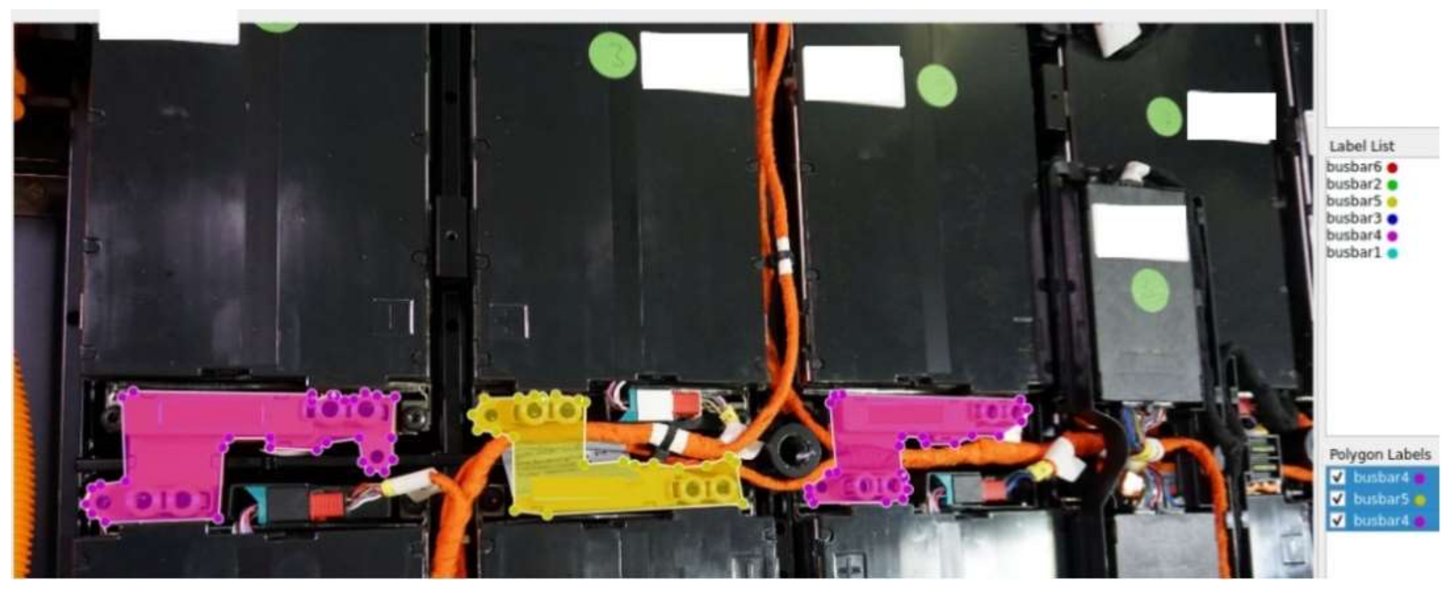
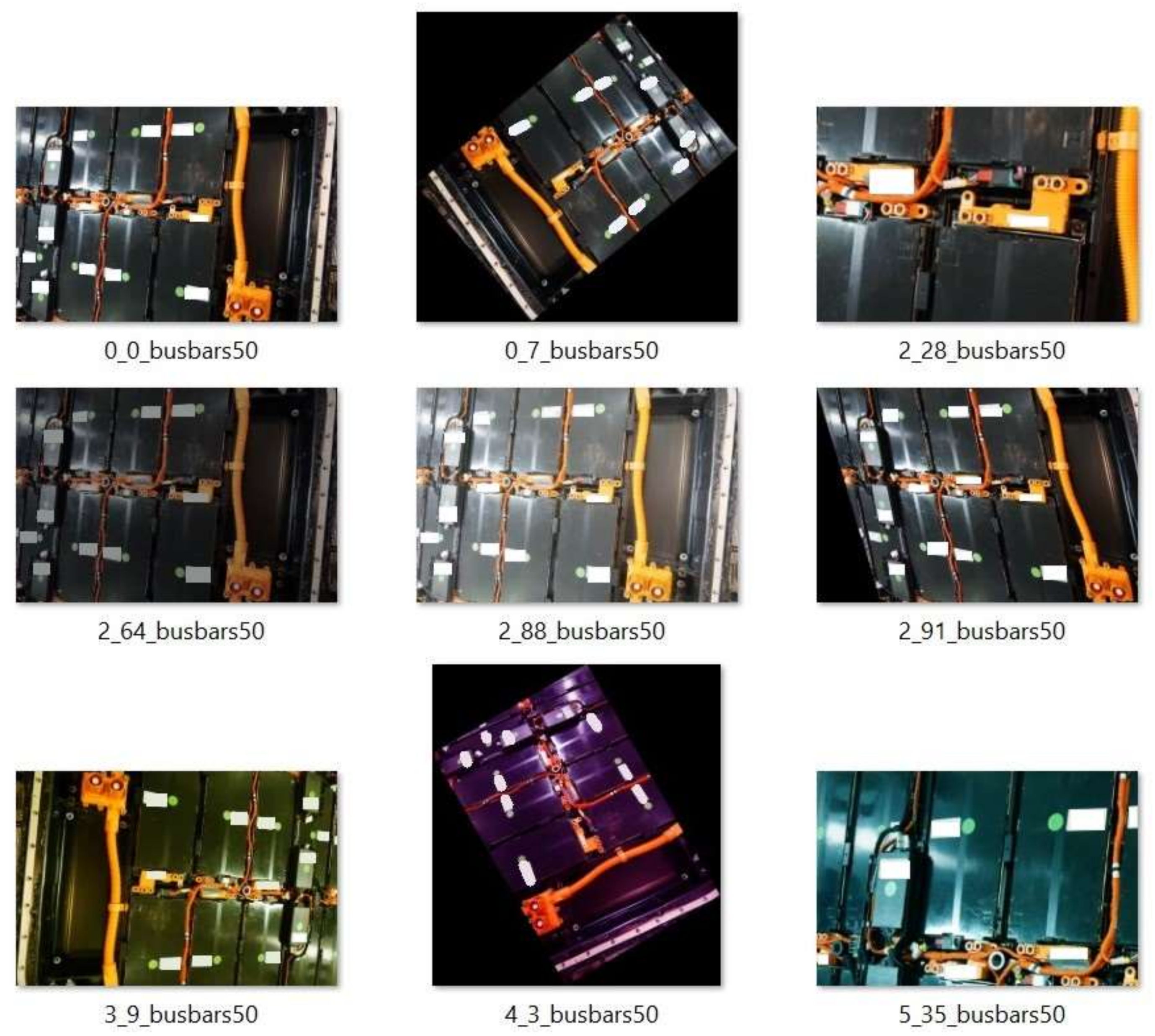
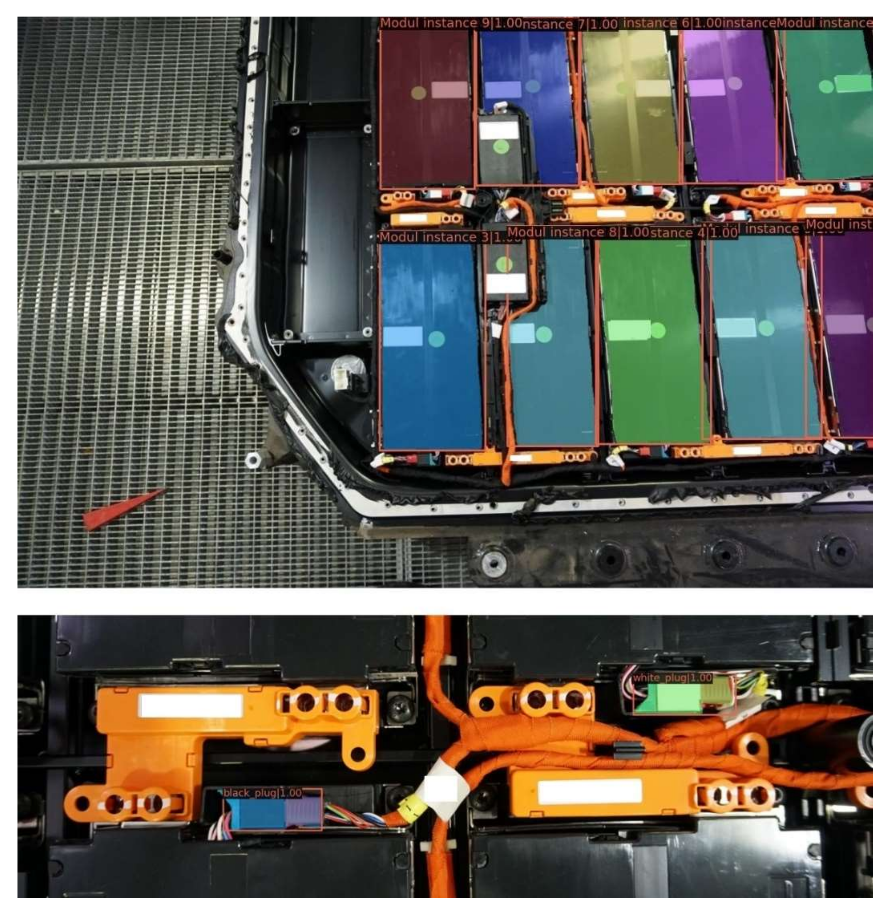
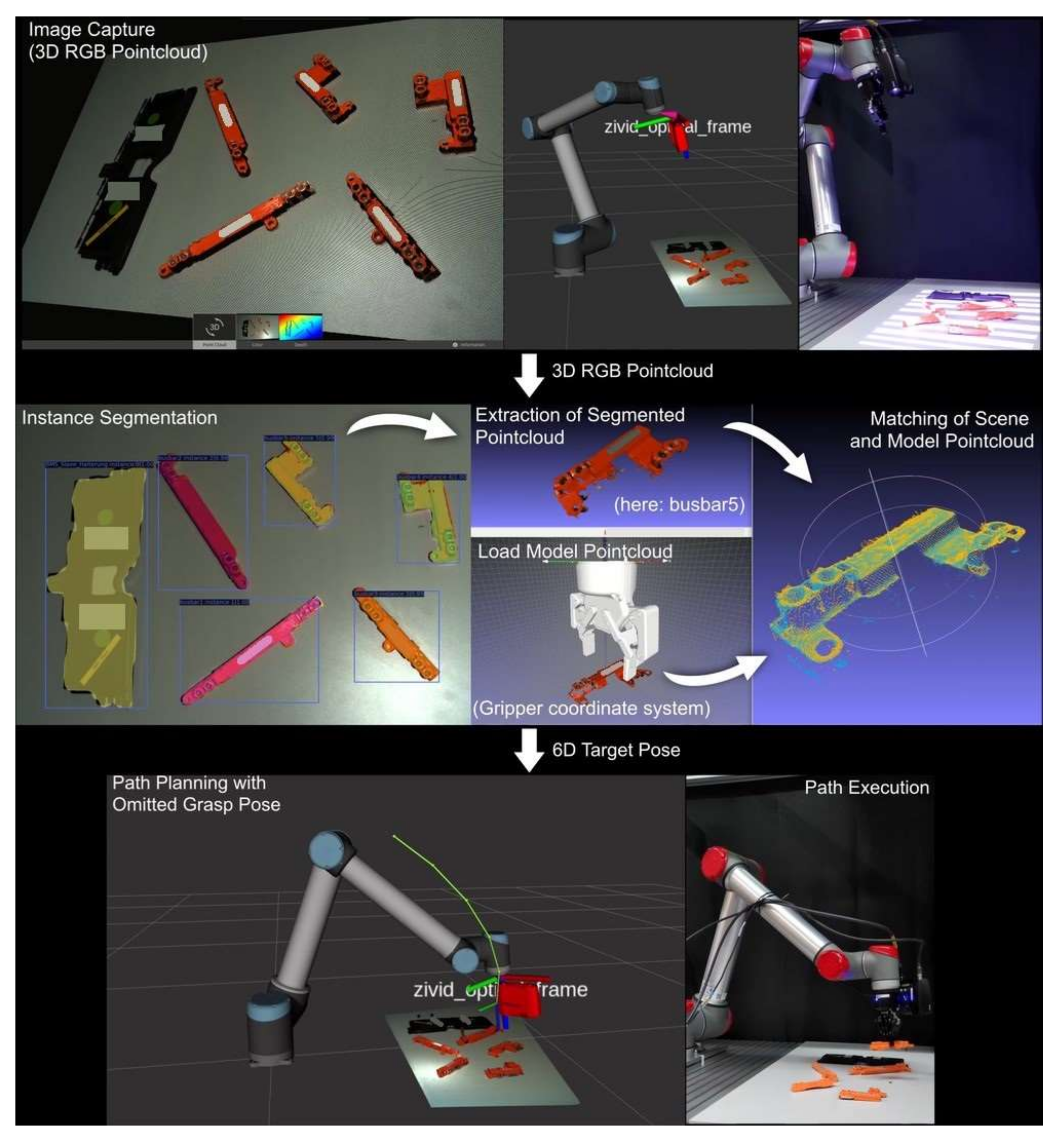
3.1.2. Instance Segmentation

This section includes the procedure of generating training datasets, meaning the annotation of images and using augmentation methods to enlarge the dataset, and the selection of a network architecture for instance segmentation.
Using the captured images datasets for training of an instance segmentation networks were created using Labelme [23], an open-source annotation tool. This annotation process is shown in Figure 9 with the example of the busbars.
The following components were annotated:
  • Screws on the lid
  • Switch box
  • Modules
  • Busbars, six different types
  • Plugs
  • Case interface
  • BMS Slave mounting
  • Main power wire consisting of side parts, a middle part, pipes and clips
One respective dataset consisted of 30–200 images and was subsequently enlarged by the factor of up to 600 using data augmentation methods such as cropping, rotation, skew, variation in lightning, and RGB channels from the library CLodSA [24]. In Figure 10, a selection of augmented images resulting from one original image (top left) are depicted. The goal of data augmentation is to easily generate a variety of training images to increase the robustness and generalization of the trained network while reducing the amount of images to be annotated and labeled by hand.
There were two instance segmentation networks that were evaluated:
  • Mask Scoring R-CNN [25,26] which uses a classic ResNet backbone
  • Mmdetection library: Mask R-CNN with Swin transformer [27,28,29] backbone
The Mask Scoring R-CNN network is based on a classic CNN-based ResNet backbone which has been established for years while the latter is based on the attention-based Swin Transformer which originates from the language processing domain and has recently been adapted to vision problems. The latter showed significantly better performance and accuracy on our datasets. The results for the selected components–the modules and the black/white plugs–are demonstrated in Figure 11.

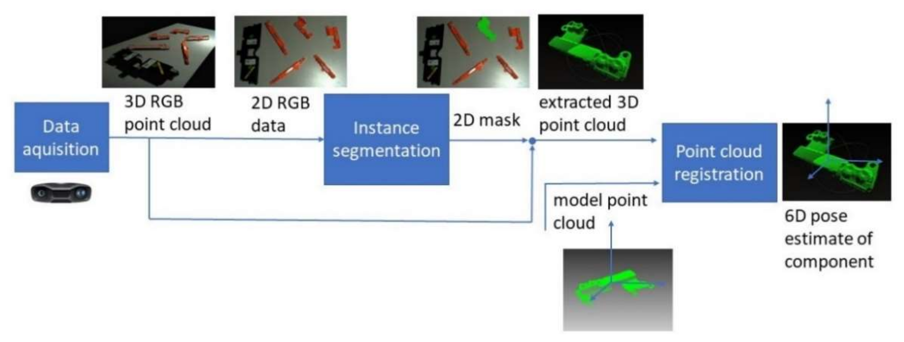
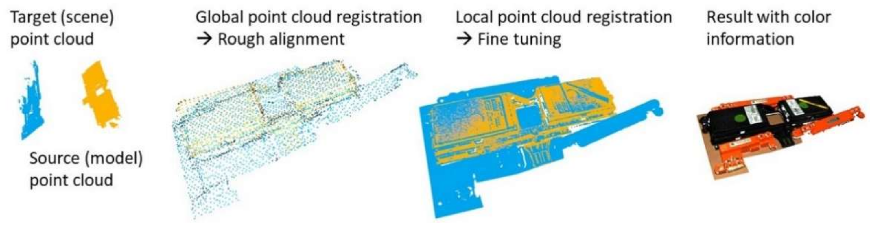
3.1.3. Point Cloud Registration

This section covers the point cloud registration pipeline to match the scene point cloud of the component, that was detected by the instance segmentation, to a model point cloud to estimate the exact pose of the component.
Point cloud registration algorithms can be grouped into local and global registration approaches. Global algorithms are able to find a roughly suitable transformation for highly misaligned point clouds, while local algorithms iteratively increase the transformation accuracy but rely on an already close initial guess. Therefore, the hybrid use of both methods is common, where the global algorithm provides the initial estimate for the local one.
Here, the so-called Fast Point Feature Histograms (FPFH) approach using the Open3D [30,31] library is used for the global registration while for the local registration the Iterative Closest Point (ICP) approach is chosen. The point cloud registration pipeline is exemplary depicted for the BMS Slave Mounting in Figure 12. Here, it becomes visible how the highly misaligned, due to translation and rotation, point clouds are roughly matched by the global registration algorithm. The transformation is then further refined by the local registration and the output with color information is shown.

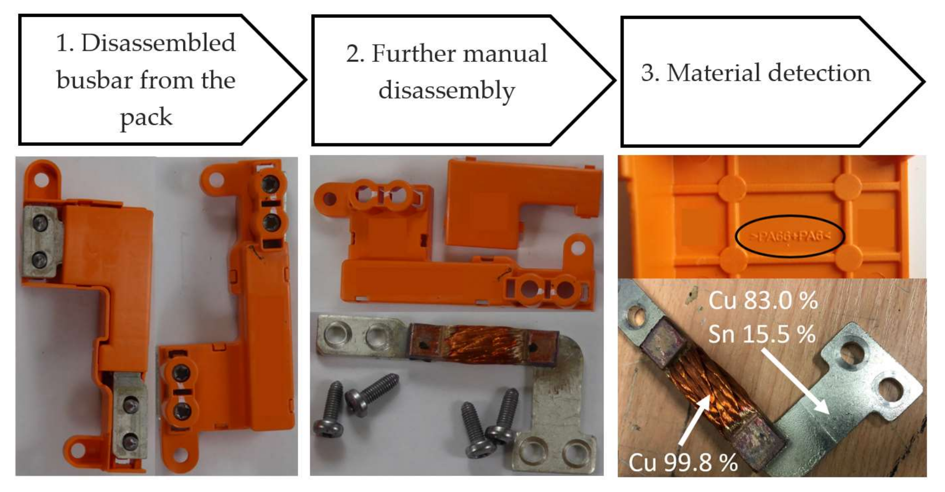
3.2. Sensor-Based Material Detection

Accompanied with the automated disassembly, the subsequent sorting process can be automated by the application of sensor-based sorting and/or material detection. Next to the automation of disassembly, the automatic sorting of the disassembled components according to the type of material is investigated. Here, the sensor technology can be used on the robot infrastructure, such as an RGB-camera (e.g., Zivid Two) or as a stationary system, that takes measurements of a moving material (e.g., on a conveyor belt). Various sensor-based sorting technologies, shown in Table 1, are used in circular economy so far, which can be used in single or in combined applications.
Except for electromagnetic induction (IND), each of the sensor technologies that is described requires a radiation source (emitter) and a detector. The former emits electromagnetic radiation of a defined wavelength range. The detector detects the radiation that is altered by substance-specific interactions with the sample under investigation, which is evaluated by software. Usually, certain features in the spectrum are compared with reference spectra from a database by software, thus enabling the characterization of the sample. In sorting technology, the subsequent addition of separation technology enables selected substances to be separated from a material stream. Sensor technologies such as RGB, NIR, and XRF a 3D-LT measure on the surface of an object. For an optimized measuring result, the object must be clean and not be covered. Detection of module cathode chemistry is not yet possible with the mentioned technologies.
The focus in this paper is on the detection of disassembled pre-sorted periphery fractions from the pack level (see Section 2.2), like:
  • Busbars
  • Wires
  • Screws
  • Housing
  • Electronic (e.g., battery management system)
  • Residues (e.g., rubber)
The periphery fractions still represent a kind of composite after the disassembly process (e.g., busbars made of copper and polymers or aluminum and polymers). Surface treatments such as paint (on housings or similar) also pose a challenge for sensor technologies that measure the surface (XRF, NIR). For the investigation of the polymer fractions, it is necessary to check whether the types of polymers that are used (polyamide 6 (PA 6), polyamide 6.6 (PA 6.6), glass-reinforced plastic (GRP), or carbon fiber-reinforced polymers (CFRP)) can be recognized and whether the current coloring (orange for high volt, black for the other parts) further influences this recognition. Therefore, pretreatment is required before using sensor-based sorting. Generally, the following sensors in Table 2 can be used for preconditioned material flows based on [39,40]. As screws are relatively homogeneous and can be stored separately in the disassembly process, they do not have to be sorted with sensors and are not listed in the table. The residues are to be disposed of without sorting.
For a recovery of polymer and metal parts, busbars need to be shredded because the claddings are plugged together with click connections and are not easily detachable. NIR can be used to recover polymers and with XRT aluminum and copper. For a more detailed identification of metals or alloys, XRF or LIBS can be used. Wires need to be crushed as well before sensor-based sorting. A 3D-LT can identify the wires by their geometric structure, and RGB or XRT can be used to separate copper and aluminum wires. In addition to sensor-based material identification, information can also be provided via a label, which is presented in the following.

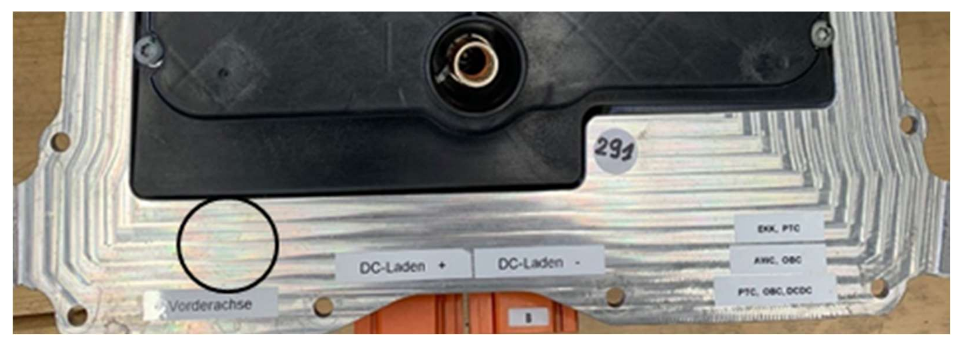
3.3. Labeling as a Support of Disassembly and Sorting Process

Until now, lithium-ion-batteries are labeled with a “Li-ion” symbol as seen in Figure 13, according to IEC 62902 [41] and the capacity [2]. This label does not provide sufficient information for a safe disassembly process and a high-quality recycling [42]. Additional data matrix codes, which are printed by the manufacturers on different battery components, are not readable now. As mentioned in Section 2.1, a battery passport (QR code) and more detailed information on the battery in electric vehicles are planned with the new European Battery Regulation. A labeling system has been developed here taking these preconditions into account and with the aim to support the (automated) disassembly process and an early separation of the different components. Hence, the label contains a wide range of information regarding the discharging and opening of battery packs, removal, and module separation by their cathode chemistry.
The regarded parameters can be divided into five categories:
  • Identification of the individual battery pack
  • General information about the battery pack (including discharging information)
  • Battery module
  • Battery cell (including the detailed cell chemistry)
  • Disassembly instructions
Each battery pack is to be given its own identifier in the future. An identification code can be used to link the identifier with essential data about the pack, if it is placed together with the QR code. The recommendation for an identity code is shown in Figure 13 and illustrates the equipment manufacturer (OEM), the engine, the battery wattage, and the year of manufacture. This information can help to classify the battery system before further information is accessible by the passport/label with QR code. Additionally, a (five-digit) specific identity code is required to enable the unique identification of each battery as claimed by the battery regulation.
One of the general parameters of the battery pack is the discharging information. For safety reasons, it is recommended to discharge the battery pack before the first step of disassembly (see Section 2.2). The battery pack is connected to the electric vehicle via a high-voltage (HV) and a low-voltage (LV) plug. The battery management system that is located in the battery pack controls, among other things, the charging and discharging process of the battery pack and is supplied with power (e.g., 12 V) via the vehicle’s electrical system [43]. The battery management system communicates with the low-voltage connection via so-called CAN bus interfaces (controller area network). In addition, the battery management system controls the main relays that connect to the high-voltage terminals and switches off in the event of a fault. If the relays are open, the connection to the vehicle’s electrical drive system is interrupted [43]. This means that if the battery will be disassembled, the relays are open and discharging is not possible. For a controlled discharging before first step of disassembly, the specific connector models of the high-voltage plug and low-voltage plug, the CAN Connections, the necessary current flows for the battery management system (e.g., 12 V), as well as the specific release commands must be given by the OEM. These data are not required under the new battery regulation but is essential for a safe disassembly. Optional discharging processes work by connecting an electric load to the main poles behind the high-voltage connector [44]. For this discharge methodology, the battery voltage has to be known, which must be given in the battery passport. Further general pack information are the dimensions of the system (length, width, height) and the weight, for a suitable disassembly device and fixation of the battery system [45]. A visual illustration of the battery pack, such as an exploded diagram is necessary due to the battery regulations. For an automated disassembly, CAD-files (Computer-Aided Design) with specific data (see below) of each component can support the automation of the process.
Electric vehicle modules often consist of inseparable compounds, so they are usually shredded rather than disassembled down to the cell level. For automation of the disassembly, the dimensions and weight must be specified so that the design of the robotic system can be adapted. For the construction or selection of the suitable shredder, a mandatory information in the labeling system would be the dimensions of the module. If a disassembly of the modules down to cell level is planned in the future, further information about the cells, e.g., design (pouch, prismatic, cylindrical), weight, and dimensions, are required.
As mentioned before, lithium-ion batteries are labelled with a “Li-ion” symbol. However, used cathode chemistry can differ in batteries from electric vehicles, e.g., nickel manganese cobalt (NMC), nickel cobalt aluminum (NCA), or lithium iron phosphate (LFP). Metallurgical recycling processes are generally more efficient if they are adjusted for similar chemical compositions [46]. Furthermore, anode and cathode chemistry as well as the electrolyte contain critical substances (e.g., graphite, lithium, cobalt), so that a labeling of the composition in the battery passport is strongly recommended as well as demanded by the European Battery Regulation.
The main part of a labeling system are the disassembly instructions, which contain the type and number of connections, the needed tools, and a warning in case of danger of damage to the parts for each individual disassembly step.
For an indication of the warnings in each step, a number system with the following coding is proposed, based on [47]:
  • 0 = no danger
  • 1 = electric shock (can lead to death of a person or overheating of the battery up to fire)
  • 2 = chemical hazard (e.g., leakage of electrolyte or carcinogenic substances (cobalt, lithium)
  • 3 = thermal hazard (due to mechanical hazard and leaking electrolyte, the carbonates of the electrolyte are highly flammable and form an explosive atmosphere with aerial oxygen)
A specification of the disassembled fractions such as the material composition in the disassembly instructions could improve the pre-sorting before recycling. Then the robot or manual disassembler could sort the materials into material-specific fractions. In particular, this would improve the separation of modules with different cathode materials. For automation of the disassembly, the disassembly instructions could be supplemented with information for the robot algorithms. With data such as coordinates and specific commands (“lift”, “cut”, “screw”) for each disassembly step and object (e.g., “lid”, “wire”; “module”), the automation process could be facilitated. The coordinates would be linked to a CAD-Model or digital-twin in this case. Since these data are currently not available, a new approach using instance segmentation is being developed here (see Section 4.1). The mentioned parameters for a labeling system are summarized in Figure 14.
This multitude of required data per battery pack that should be provided by a battery label, suggests the use of a database which can be accessed, e.g., automatically with a QR code (as it is also recommended in the proposal of the Battery Regulation) and additionally manually with the identification code (see Figure 13). In this context, it should be examined whether the data for the battery label could be merged with the IDIS database [48], for example. The latter already provides dismantling information for end-of-life vehicles. In addition to the application of a QR code, a data matrix code would also be suitable for accessing the database. Barcodes are not recommended for data provision due to the more inflexible readout option (mostly from left to right) and the low storage capacity (max. 25 digits [49]). A RFID chip as a further option can be read without visual contact but requires a corresponding infrastructure and a reader to detect the radio waves [50]. It is also considered to be of little advantage for the automatic identification of lithium-ion batteries.
The recommended labeling concept is shown in Figure 15. In principle, the data that are required for the label can be provided directly by the battery and pack manufacturers, since they already have the relevant information and knowledge through battery (pack) development. During the production of the battery packs, the label should be applied in a weather-protected manner so that it is not affected by the changing conditions during the use phase or when the battery is modified, e.g., for a second-use application. This argues for multiple labeling of a battery pack. For example, information on the cathode chemistry (NMC, LFP, NCA, etc.) should also be provided at the module level (e.g., extending the already required “Li-ion” labeling: “NMC-Li-ion” or “LFP-Li-ion”). A safe localization for the label on the battery pack could be the lid of the pack housing, as this is usually located between the vehicle floor and the battery pack and thus is mainly protected from environmental influences. Challenges for the implementation of the label exist regarding the following aspects:
  • Uniform and comprehensible entry of data into the database
  • Updating/maintenance of the battery pack data over the entire life cycle (e.g., when components are replaced)
  • Ensuring the legibility of the label and the availability of data over the entire life cycle of the battery (cover of the pack housing)
  • Regulation of access to the database (only authorized third parties)
  • Gaining the acceptance of the vehicle/battery manufacturers (partly prescribed by law via battery regulation).

4. Results and Discussion

In the following section, the initial results from the digitization and automation of the disassembly process are presented. In addition, the first sensor-based material detections of battery components are presented.

4.1. Validation of the Vision Pipeline in a Demonstrator Setup for Automation of Disassembly

In this section, the described pipeline in Figure 5 is validated using a demonstrator setup. This setup consists of a Universal Robots UR10 robot with the hand-eye-calibrated Zivid Two camera mounted on the robot wrist. For this specific scenario, a setup of five busbars and the BMS Slave mounting were placed in front of the robot. The objective of the validation is the automated grasping of a component using the camera system, detection, and pose estimation as described in Section 3.1.
The network was trained with 25 images of variations of this setup that were further augmented. A state machine that was implemented using Flexbe [51] connects the various actors, meaning that it activates the instance segmentation or the robot control with motion planning. Furthermore, the state machine transfers information as the desired component via user input to the vision actor or the obtained robot goal pose from the vision actor to the robot motion planning actor.
In Figure 16, the described demonstrator is depicted. In the first row, the data acquisition of the 3D RGB point cloud using the Zivid Two camera that is mounted on the EEF is shown. In the second row, the instance segmentation, extraction of the point cloud (here: busbar5), and point cloud registration with the model point cloud in the gripper coordinate system is visualized. Finally, the last row demonstrates the path planning (via Moveit! [52]) to the obtained goal pose and path execution with a successful grasp of busbar5.
This way, the function principle of the vision pipeline was validated. The transferability of a grasping action to other disassembly steps, such as loosening a screw, is not limited as this way any EEF pose in relation to the component can be determined.
It is currently evaluated if, especially the point cloud registration algorithm, remains robust and performant for other components or assembly scenarios. In the tests that were carried out, the algorithm proved itself to be robust and performant for components with a very individual geometry, i.e., a geometry where every small area has very individual geometric features. The current global registration algorithm iteratively chooses three random points from the source point cloud, evaluates the geometric features at this point, and then finds corresponding points with similar features in the target cloud. Therefore, it can be successfully applied on a wide range of battery components such as the busbars or the mounting of the BMS Slaves. However, due to its function principle, the algorithm showed drawbacks when it is applied to geometries that appear as a surface without significant depth or curvature information and geometries that are almost symmetric; both are the case for the battery modules.
In Figure 17, the 2D image of the module is depicted and the contours are visualized. The corresponding point cloud, which demonstrates the sparse depth or curvature information, is shown in Figure 18. Therefore, the current focus lies on developing point cloud registration pipelines that target these weaknesses.

4.2. Sensor-Based Material Composition Detection

The sensor-based detection of the material composition includes the characterization of the disassembled battery components. For this purpose, the composition of two different module housings and busbars was measured with an XRF handheld spectrometer. The advantage of this method is the fast and non-destructive measurement of the composition. For comparability, the measuring time for all of the measurements was 120 s. The time is set as a maximum. All the measurements have been repeated three times. The following results represent the mean values from these three measurements.
Concerning the battery pack level, two different black lacquered housings (from Audi e-tron pack and a VW pack) were analyzed, which are shown in Figure 19a,b. As the XRF handheld spectrometer measures the surface (see Section 3.2), this has to be free of varnish and impurities. The varnish was first removed and then the measuring point was cleaned with ethanol so as not to falsify the results. The measuring points are marked in white and shown in Figure 19. The measurements were carried out on the carrier of the enclosure in each case (see measuring point 1 and 3). The pack of Audi e-tron (b) has already been disassembled so that a measurement of the housing below a module (measuring point 2) was also possible.
The two cases of the different battery packs differ in composition. The VW pack housing is based on a steel alloy, while the Audi e-tron pack housing is made of an aluminum alloy. The compositions of the housings are shown in Table 3. Only the elements with the greatest concentrations are shown.
For the battery module level, the housing of modules were analyzed. These modules are from the battery packs in Figure 19. The modules and the measuring points that are marked in black are shown in Figure 20. The module (a) is from the VW pack. The module in Figure 20b is from the Audi e-tron. Before the measurement, the measuring point is also cleaned with ethanol.
The alloys of the module housings are also different and shown in Table 4. The module housing (a) is made of an aluminum alloy and the module housing (b) is made of a steel alloy.
Further, a switch box, shown in Figure 21, was measured. As it can be seen in Table 5, it is also an aluminum alloy.
In addition to the measurements on the housings and modules, the busbars were also analyzed. These represent a composite after disassembly and must be further disassembled manually. As can be seen in Figure 22, the insulation is an orange polymer with a PA6 + PA66 composition that is attached to the busbar. The busbar consists of two end pieces with holes for attachment to the module and a center piece that is made of pure copper. The end pieces are made of tinned copper.
Further polymer components, e.g., the battery management brackets, were made of black polymer PA6 or PA6.6 with additives such as glass fibers or glass beads.
The first results with handheld analyzers could be generated from different pack and module housing components and busbars. Thus, the composition of the materials can be estimated. The extent to which the materials can also be measured automatically with stationary sensors with shorter measuring times is to be examined in the further course. The polymer components, on the other hand, were stamped with the type of polymer and could thus be precisely assigned. The extent to which these materials can also be detected with a near-infrared device is to be examined in further steps. Black polymers in particular present a challenge in sorting technology, as they cannot be measured with a classic near-infrared sensor.

5. Conclusions and Outlook

In order to ensure high-quality recycling at the end of life, battery packs have to be disassembled to module level first before the separated components (e.g., battery modules) are then further processed by mechanical and metallurgical recycling processes. Considering the high expected return quantity of EoL EV battery packs and the lack of data for pack structure, automatic disassembly of the packs has to be investigated. An approach to automate the disassembly to module level has been presented here.
The central components of an automated disassembly comprise of an automated detection and pose estimation of the components. Based on this, the derivation of goal positions of the robot end effector (EEF) for disassembly operations such as component grasping are derived. The full computer vision pipeline, starting with image capture using a high-resolution depth camera, image processing by means of instance segmentation and point cloud registration to the robotic motion planning, and execution was implemented in a demonstrator. Within this setup, the automated grasping of a battery component was performed. The developed pipeline is generally transferable to other disassembly steps, e.g., loosening screws. As a next step, the robustness of this pipeline and its applicability for other components, such as those with symmetric geometries such as the battery modules, has to be evaluated and improved. Additionally, an approach needs to be defined to create a global map of the battery as the camera in its optimal working distance can only capture parts of the battery. Another aspect is the future investigation of the use of a force torque-based approach for the removal of components that are glued to a surface (e.g., battery modules). Using reinforcement learning (RL) an agent can learn an efficient control strategy that is based on feedback from the robot state.
At a later stage, the proposed concept must be further evaluated and improved by setting up a pilot disassembly plant for battery packs. Therefore, in addition to the automatic detection of the individual components to be disassembled, technology concepts that can overcome the described technological challenges of automated disassembly on the tool side have to be developed.
Regarding the peripheral components, a concept for sensor-based automated sorting has to be investigated. A first approach, which will be examined in more detail, is the use of an XRF hand-spectrometer, as the first results show that the different alloys that are used in the battery packs can be distinguished from each other using this kind of sensor. The difficulties here are coatings, because they prevent the detection of the underlying material. However, black components and composites also pose major challenges. Up til now, black polymers could not be detected using conventional techniques, and composites cannot be sorted by type. Current sensor developments could allow this for black polymers in the future. The materials that are used could also be included in the label, which was proposed here. The future EU battery regulation also provides for a battery passport with information on the chemical composition and (manual) dismantling instructions. Based on this regulation, the automation of disassembly and sorting that are presented here will be further developed in order to support efficient and intelligent processing and high-quality recycling.

Author Contributions

Four institutes are working on the project DemoSens. M.Z. and S.H. from IWARU is handling the project coordination and has a main part for the labeling concept and the sensor-based sorting. D.K., N.K. and C.O. (PEM) provided the expertise for the disassembly of battery packs and set up the pilot plant within the project. C.I., K.Z. and Y.Z. (IfU) developed the vision pipeline for automatic detection of components and the derivation of robot trajectories for an automation of the disassembly process. A.D. is an expert for quality management and performed material flow analysis by using ICP-OES. S.F. is the institute leader of the IWARU, A.K. of PEM, B.F. of IME, and C.H. the group leader of IfU. All authors have read and agreed to the published version of the manuscript.

Funding

The project (DemoSens) on which this report is based is funded by the German Federal Ministry of Education and Research under the funding code 03XP0314A-C. The responsibility for the content of this publication lies with the author.

Institutional Review Board Statement

Not applicable.

Informed Consent Statement

Not applicable.

Data Availability Statement

The data presented in this study are available on request from the corresponding author. The data are not publicly available due to sensitive manufacturer information.

Conflicts of Interest

The authors declare no conflict of interest. The funders had no role in the design of the study; in the collection, analyses, or interpretation of data; in the writing of the manuscript, or in the decision to publish the results.

References

  1. Climate Action Programme 2030. Available online: https://www.bundesregierung.de/breg-en/issues/climate-action (accessed on 1 April 2022).
  2. Directive 2006/66/EC of the European Parliament and of the Council of 6 September 2006 on Batteries and Accumulators and Waste Batteries and Accumulators and Repealing Directive 91/157/EEC: Battery Directive. 2006. Available online: https://eur-lex.europa.eu/legal-content/EN/TXT/PDF/?uri=CELEX:02006L0066-20131230&rid=1 (accessed on 1 April 2022).
  3. Proposal for a Regulation of the European Parliament and of Thecouncil Concerning Batteries and Waste Batteries, Repealing Directive 2006/66/EC and Amending Regulation (EU) No 2019/1020. 2020. Available online: https://eur-lex.europa.eu/resource.html?uri=cellar:4b5d88a6-3ad8-11eb-b27b-01aa75ed71a1.0001.02/DOC_1&format=PDF (accessed on 1 April 2022).
  4. Batteries and Waste Batteries ***I Amendments Adopted by the European Parliament on 10 March 2022 on the Proposal for a Regulation of the European Parliament and of the Council Concerning Batteries and Waste Batteries, Repealing Directive 2006/66/EC and Amending Regulation (EU) No 2019/1020 (COM(2020)0798–C9-0400/2020–2020/0353(COD)): First Reading. 2022. Available online: https://www.europarl.europa.eu/doceo/document/TA-9-2022-0077_EN.pdf (accessed on 2 April 2022).
  5. Gerbers, R.; Wegener, K.; Dietrich, F.; Dröder, K. Safe, Flexible and Productive Human-Robot-Collaboration for Disassembly of Lithium-Ion Batteries. In Recycling of Lithium-Ion Batteries: The LithoRec Way; Kwade, A., Diekmann, J., Eds.; Springer: Cham, Switzerland, 2018; pp. 99–126. ISBN 978-3-319-70571-2. [Google Scholar]
  6. Baum, Z.J.; Bird, R.E.; Yu, X.; Ma, J. Lithium-Ion Battery Recycling─Overview of Techniques and Trends. ACS Energy Lett. 2022, 7, 712–719. [Google Scholar] [CrossRef]
  7. Kampker, A.; Wessel, S.; Fiedler, F.; Maltoni, F. Battery pack remanufacturing process up to cell level with sorting and repurposing of battery cells. J. Remanuf. 2021, 11, 1–23. [Google Scholar] [CrossRef]
  8. Zwicker, M.; Moghadam, M.; Zhang, W.; Nielsen, C.V. Automotive battery pack manufacturing–A review of battery to tab joining. J. Adv. Join. Process. 2020, 1, 100017. [Google Scholar] [CrossRef]
  9. Schäfer, J.; Singer, R.; Hofmann, J.; Fleischer, J. Challenges and Solutions of Automated Disassembly and Condition-Based Remanufacturing of Lithium-Ion Battery Modules for a Circular Economy. Procedia Manuf. 2020, 43, 614–619. [Google Scholar] [CrossRef]
  10. Li, L.; Zheng, P.; Yang, T.; Sturges, R.; Ellis, M.W.; Li, Z. Disassembly Automation for Recycling End-of-Life Lithium-Ion Pouch Cells. JOM 2019, 71, 4457–4464. [Google Scholar] [CrossRef] [Green Version]
  11. Velázquez-Martínez, O.; Valio, J.; Santasalo-Aarnio, A.; Reuter, M.; Serna-Guerrero, R. A Critical Review of Lithium-Ion Battery Recycling Processes from a Circular Economy Perspective. Batteries 2019, 5, 68. [Google Scholar] [CrossRef] [Green Version]
  12. Wegener, K.; Chen, W.H.; Dietrich, F.; Dröder, K.; Kara, S. Robot Assisted Disassembly for the Recycling of Electric Vehicle Batteries. Procedia CIRP 2015, 29, 716–721. [Google Scholar] [CrossRef]
  13. Rallo, H.; Benveniste, G.; Gestoso, I.; Amante, B. Economic analysis of the disassembling activities to the reuse of electric vehicles Li-ion batteries. Resour. Conserv. Recycl. 2020, 159, 104785. [Google Scholar] [CrossRef]
  14. Wegener, K.; Andrew, S.; Raatz, A.; Dröder, K.; Herrmann, C. Disassembly of Electric Vehicle Batteries Using the Example of the Audi Q5 Hybrid System. Procedia CIRP 2014, 23, 155–160. [Google Scholar] [CrossRef] [Green Version]
  15. Hellmuth, J.F.; DiFilippo, N.M.; Jouaneh, M.K. Assessment of the automation potential of electric vehicle battery disassembly. J. Manuf. Syst. 2021, 59, 398–412. [Google Scholar] [CrossRef]
  16. Abdelbasir, S.M.; Hassan, S.S.M.; Kamel, A.H.; El-Nasr, R.S. Status of electronic waste recycling techniques: A review. Environ. Sci. Pollut. Res. Int. 2018, 25, 16533–16547. [Google Scholar] [CrossRef]
  17. Steward, D.; Mayyas, A.; Mann, M. Economics and Challenges of Li-Ion Battery Recycling from End-of-Life Vehicles. Procedia Manuf. 2019, 33, 272–279. [Google Scholar] [CrossRef]
  18. Blankemeyer, S.; Wiens, D.; Wiese, T.; Raatz, A.; Kara, S. Investigation of the potential for an automated disassembly process of BEV batteries. Procedia CIRP 2021, 98, 559–564. [Google Scholar] [CrossRef]
  19. Gerlitz, E.; Greifenstein, M.; Hofmann, J.; Fleischer, J. Analysis of the Variety of Lithium-Ion Battery Modules and the Challenges for an Agile Automated Disassembly System. Procedia CIRP 2021, 96, 175–180. [Google Scholar] [CrossRef]
  20. Harper, G.; Sommerville, R.; Kendrick, E.; Driscoll, L.; Slater, P.; Stolkin, R.; Walton, A.; Christensen, P.; Heidrich, O.; Lambert, S.; et al. Recycling lithium-ion batteries from electric vehicles. Nature 2019, 575, 75–86. [Google Scholar] [CrossRef] [PubMed] [Green Version]
  21. Meng, K.; Xu, G.; Peng, X.; Youcef-Toumi, K.; Li, J. Intelligent disassembly of electric-vehicle batteries: A forward-looking overview. Resour. Conserv. Recycl. 2022, 182, 106207. [Google Scholar] [CrossRef]
  22. Zivid. See More. Do More. Zivid Two Industrial 3D Camera-Zivid. Available online: https://www.zivid.com/zivid-two (accessed on 19 April 2022).
  23. GitHub. GitHub-Wkentaro/Labelme: Image Polygonal Annotation with Python (Polygon, Rectangle, Circle, Line, Point and Image-Level Flag Annotation). Available online: https://github.com/wkentaro/labelme (accessed on 19 April 2022).
  24. GitHub. GitHub-Joheras/CLoDSA. Available online: https://github.com/joheras/CLoDSA (accessed on 19 April 2022).
  25. GitHub. GitHub-Zjhuang22/Maskscoring_rcnn: Codes for Paper “Mask Scoring R-CNN”. Available online: https://github.com/zjhuang22/maskscoring_rcnn (accessed on 19 April 2022).
  26. Huang, Z.; Huang, L.; Gong, Y.; Huang, C.; Wang, X. Mask Scoring R-CNN. In CVPR 2019, Proceedings of the 2019 IEEE/CVF Conference on Computer Vision and Pattern Recognition (CVPR), Long Beach, CA, USA, 15–20 June 2019; IEEE Computer Society: Los Alamitos, CA, USA; Washington, DC, USA; Tokyo, Japan, 2019; pp. 6402–6411. ISBN 978-1-7281-3293-8. [Google Scholar]
  27. GitHub. GitHub-Open-Mmlab/Mmdetection: OpenMMLab Detection Toolbox and Benchmark. Available online: https://github.com/open-mmlab/mmdetection (accessed on 19 April 2022).
  28. He, K.; Gkioxari, G.; Dollár, P.; Girshick, R. Mask R-CNN. arXiv 2017, arXiv:1703.06870v3. [Google Scholar]
  29. Liu, Z.; Lin, Y.; Cao, Y.; Hu, H.; Wei, Y.; Zhang, Z.; Lin, S.; Guo, B. Swin Transformer: Hierarchical Vision Transformer Using Shifted Windows. arXiv 2021, arXiv:2103.14030. [Google Scholar]
  30. Chen, Y.; Medioni, G. Object Modeling by Registration of Multiple Range Images. Image Vis. Comput. 1992, 10, 145–155. [Google Scholar] [CrossRef]
  31. Rusu, R.B.; Blodow, N.; Beetz, M. Fast Point Feature Histograms (FPFH) for 3D registration. In Proceedings of the 2009 IEEE International Conference on Robotics and Automation (ICRA), Kobe, Japan, 12–17 May 2009; pp. 3212–3217. [Google Scholar]
  32. Berwanger, M.; Maul, A. Principles of visual sensor technolgy. In Sensor Technologies: Impulses for the Raw Materials Industry; Nienhaus, K., Ed.; Shaker: Aachen, Germany, 2014; pp. 101–123. ISBN 9783844025637. [Google Scholar]
  33. Diekmann, J.; Sander, S.; Sellin, G.; Kwade, A. Material Separation. In Recycling of Lithium-Ion Batteries: The LithoRec Way, 1st ed.; Kwade, A., Diekmann, J., Eds.; Springer International Publishing: Cham, Switzerland, 2018; ISBN 978-3-319-70571-2. [Google Scholar]
  34. Hering, E.; Schönfelder, G. Sensoren in Wissenschaft und Technik: Funktionsweise und Einsatzgebiete; Springer: Berlin/Heidelberg, Germany, 2012; ISBN 978-3-8348-0169-2. [Google Scholar]
  35. Köpcke, M.; Warcholik, M.; Knapp, H. Principles of X-ray transmission. In Sensor Technologies: Impulses for the Raw Materials Industry; Nienhaus, K., Ed.; Shaker: Aachen, Germany, 2014; pp. 54–63. ISBN 9783844025637. [Google Scholar]
  36. Uepping, R. Sensorgestützte Sortiertechnik. In Recycling und Rohstoffe; Thomé-Kozmiensky, K.J., Goldmann, D., Eds.; TK-Verl.: Neuruppin, Germany, 2013; pp. 371–383. ISBN 9783935317979. [Google Scholar]
  37. Neubert, K.; Knapp, H.; Fietz, N. Principles of X-ray fluorescence analysis. In Sensor Technologies: Impulses for the Raw Materials Industry; Nienhaus, K., Ed.; Shaker: Aachen, Germany, 2014; pp. 88–100. ISBN 9783844025637. [Google Scholar]
  38. Schropp, C.; Raulf, K.; Robben, M. Principles of near infrared. In Sensor Technologies: Impulses for the Raw Materials Industry; Nienhaus, K., Ed.; Shaker: Aachen, Germany, 2014; pp. 131–140. ISBN 9783844025637. [Google Scholar]
  39. Steinert GmbH. E-Scrap Recycling & Sorting: Separation & Sorting through All Fractions in Electrical Scrap. Available online: https://steinertglobal.com/metal-recycling/e-scrap-recycling/ (accessed on 20 April 2022).
  40. Kranert, M. Einführung in die Kreislaufwirtschaft: Planung-Recht-Verfahren; Springer: Berlin/Heidelberg, Germanay, 2017; ISBN 978-3834818379. [Google Scholar]
  41. Secondary Cells and Batteries-Marking Symbols for Identification of Their Chemistry, IEC 62902. 2019. Available online: https://webstore.iec.ch/publication/29912 (accessed on 1 April 2022).
  42. Wang, X.; Gaustad, G.; Babbitt, C.W. Targeting high value metals in lithium-ion battery recycling via shredding and size-based separation. Waste Manag. 2016, 51, 204–213. [Google Scholar] [CrossRef] [Green Version]
  43. Koehler, U. Lithium-ion battery system design. In Lithium-Ion Batteries: Basics and Applications, 1st ed.; Korthauer, R., Ed.; Springer: Berlin, Germany, 2018; ISBN 978-3-662-53069-6. [Google Scholar]
  44. Hauck, D.; Kurrat, M. Overdischarging Lithium-Ion Batteries. In Recycling of Lithium-Ion Batteries: The LithoRec Way; Kwade, A., Diekmann, J., Eds.; Springer: Cham, Switzerland, 2018; ISBN 978-3-319-70571-2. [Google Scholar]
  45. Fleischer, J.; Gerlitz, E.; Rieβ, S.; Coutandin, S.; Hofmann, J. Concepts and Requirements for Flexible Disassembly Systems for Drive Train Components of Electric Vehicles. Procedia CIRP 2021, 98, 577–582. [Google Scholar] [CrossRef]
  46. Gaines, L.; Richa, K.; Spangenberger, J. Key issues for Li-ion battery recycling. MRS Energy Sustain. 2018, 5, 12. [Google Scholar] [CrossRef] [Green Version]
  47. Diekmann, J.; Grützke, M.; Loellhoeffel, T.; Petermann, M.; Rothermel, S.; Winter, M.; Nowak, S.; Kwade, A. Potential Dangers during the Handling of Lithium-Ion Batteries. In Recycling of Lithium-Ion Batteries: The LithoRec Way, 1st ed.; Kwade, A., Diekmann, J., Eds.; Springer International Publishing: Cham, Switzerland, 2018; pp. 39–51. ISBN 978-3-319-70571-2. [Google Scholar]
  48. IDIS 2 Group. IDIS|The International Dismantling Information System. Available online: https://www.idis2.com/index.php (accessed on 29 March 2022).
  49. Karrach, L.; Pivarčiová, E.; Nikitin, Y.R. Comparing the impact of different cameras and image resolution to recognize the data matrix codes. J. Electr. Eng. 2018, 69, 286–292. [Google Scholar] [CrossRef] [Green Version]
  50. Karygiannis, A.T.; Eydt, B.; Barber, G.; Bunn, L.; Phillips, T. Guidelines for Securing Radio Frequency Identification (RFID) Systems; NIST: Gaithersburg, MD, USA, 2007. [Google Scholar]
  51. GitHub. FlexBE. Available online: https://github.com/FlexBE (accessed on 19 April 2022).
  52. MoveIt Motion Planning Framework. Available online: https://moveit.ros.org/ (accessed on 19 April 2022).
Figure 1. Course of action in DemoSens.
Recycling 07 00048 g001
Figure 2. Schematic representation of the basic structure of the state-of-the-art electric vehicle battery packs with modular product architecture [7]. The arrows represent the physical connections between the individual components that have to be separated during disassembly.
Recycling 07 00048 g002
Figure 3. Simplified representation of the disassembly process of a typical state of the art lithium-ion battery pack.
Recycling 07 00048 g003
Figure 4. Common challenges that are caused by the product design for the process automation of battery pack disassembly (1, 2, 3, 4, 5: Audi e-tron 50 battery pack; 6: BMW i3 battery pack).
Recycling 07 00048 g004
Figure 5. Vision pipeline from image capture to final 6D pose estimation of components.
Recycling 07 00048 g005
Figure 6. Picture of a switch box (a) and the corresponding point cloud that was produced by the Realsense D435i (b).
Recycling 07 00048 g006
Figure 7. Zivid Two with projector (left) and 2D camera (right) mounted on a robot arm.
Recycling 07 00048 g007
Figure 8. Point cloud of the switch box (a), modules and busbars (b) that were captured with Zivid Two.
Recycling 07 00048 g008
Figure 9. Annotation for instance segmentation with Labelme with the example of the busbars.
Recycling 07 00048 g009
Figure 10. Examples of images that were derived by data augmentation from the original image (top left).
Recycling 07 00048 g010
Figure 11. Instance segmentation result of modules (top) and plugs (bottom).
Recycling 07 00048 g011
Figure 12. Matching of the misaligned source and target point clouds (exemplary depicted for BMS Slave Mounting).
Recycling 07 00048 g012
Figure 13. Current label for lithium-ion batteries according to [41] (a) and the recommendation for an identity code in combination with a QR code (b).
Recycling 07 00048 g013
Figure 14. Parameters for an automated disassembly and an improved recycling.
Recycling 07 00048 g014
Figure 15. Proposal for a labeling concept.
Recycling 07 00048 g015
Figure 16. Overview of the full workflow from point cloud capture to path execution by the robot.
Recycling 07 00048 g016
Figure 17. Outlined corner of a battery module (red).
Recycling 07 00048 g017
Figure 18. Point cloud of a battery module. Green dots are known data points, black areas resulting from lack of depth points.
Recycling 07 00048 g018
Figure 19. Presentation of the measuring points of the two different battery housings: (a) VW pack measuring point 1 carrier and (b) Audi e-tron measuring point 2 housing below a module and measuring point 3 carrier.
Recycling 07 00048 g019
Figure 20. Presentation of VW module (a) and Audi e-tron module (b) with the respective measuring points (marked in black).
Recycling 07 00048 g020
Figure 21. Presentation of the switch box and the black marked measuring points.
Recycling 07 00048 g021
Figure 22. Illustration of the manual disassembly process of the insulated busbars and material characterization.
Recycling 07 00048 g022
Table 1. Sensor technologies in circular economy. Physical principal and conditions.
SensorPhysical Principal and Separation FeatureConditions and Limitations
Color (RGB)
  • Provides information about the shape and color
  • Based on the detection of electromagnetic radiation in the visible spectrum (wavelength range 390 nm–780 nm) [32]
  • Detection and separation of the sample by color (e.g., copper and aluminum foils of batteries [33])
  • Localization of fractions by color and shape (see Section 3.1)
  • Surface detection
3D laser trian-gulation (3D-LT)
  • Provides information about the shape characteristics and geometry (measurement of the height profile)
  • Based on measuring the distance between transmitter generating a visible light and object [34]
  • Usually in combination with other sensors (e.g., RGB)
  • No hollow body detection
  • Volume overdetermination
X-ray transmission (XRT)
  • Provides information about the material density
  • Based on X-rays (λ = 10–0.001 nm) passing through the sample [35]
  • Depending on the density of the material, the object absorbs different amounts of radiation
  • Detection of aluminum and heavy metals (e.g., copper, tin) [36]
  • Protection against X-rays/radiation necessary
X-ray fluorescence (XRF)
  • Provides information about the chemical composition
  • Based on X-rays (λ = 10–0.001 nm) which generate a material-specific secondary radiation (fluorescence) of the sample [37]
  • Element measurement of fluorescence (e.g., alloys)
  • Long measurement time (hand-spectrometer): light metals (e.g., aluminum) can be measured from >10 s; the accuracy of the measurement results increases with the measurement time.
  • Short measurement time (10 ms in moving material): low atomic numbers (e.g., aluminum) are not directly detectable [36]
  • Protection against X-rays/radiation necessary
  • Surface detection
Induction (IND)
  • Provides information about the electrical conductivity of an object
  • Based on a generated electromagnetic field, that changes when an electrically conductive object approaches it. The resulting field changes and signal fluctuations are measurable [36]
  • Low spatial resolution
Near-infrared (NIR)
  • Provides information about the material property (especially polymer * type)
  • Based on near-infrared radiation (780–3000 nm), polymer (1200–2000 nm) [36]
  • Molecules of the sample are excited by the radiation and absorb material-specific wavelengths. The remaining wavelengths are reflected and measured [36]
  • Surface detection
  • No reflection and detection of black materials [38]
* Here synthetic polymer (e.g., polyethylene (PE), polypropylene (PP), polyamide (PA), polyvinyl chloride (PVC)).
Table 2. Sensor-based sorting of periphery fractions from a battery pack.
Material FlowPreconditionRGB3D-LTXRTXRFLIBSINDNIR
BusbarsCrushing, magnetic, and eddy current separation x(x)(x) x
WiresCrushing, magnetic, and eddy current separationxxx x
Hou-singCrushing xxx
ElectronicsCrushing, magnetic, and eddy current separationxx xx
Table 3. Presentation of the results of the XRF hand-spectrometer measurements.
Measuring PointFe
[%]
Al
[%]
Mg
[%]
Mn
[%]
Zn
[%]
C
[%]
Si
[%]
Cr
[%]
197.890.44n/a0.600.60n/a0.210.04
20.2197.890.600.6n/a0.040.44n/a
3n/a98.020.55n/an/an/a0.85n/a
Table 4. Presentation of the results of the XRF hand-spectrometer measurements of the module housing.
ModuleAl
[%]
Fe
[%]
Cr
[%]
Ni
[%]
Mg [%]Mn [%]C
[%]
Si
[%]
Cu
[%]
Sn
[%]
V
[%]
(a)92.760.230.21n/a5.960.49n/a0.27n/an/an/a
(b)n/a71.8817.978.18n/a1.980.33n/a0.210.120.11
Table 5. Presentation of the results of the XRF hand-spectrometer measurements of a switch box.
Switch BoxAl
[%]
Si
[%]
Fe
[%]
Mn
[%]
87.3211.760.215.96
Publisher’s Note: MDPI stays neutral with regard to jurisdictional claims in published maps and institutional affiliations.

