Article

Properties of High-Flowability Liquefied Stabilized Soil Made of Recycled Construction Sludge

by
Yuji Shigematsu
1,
Shinya Inazumi
2,*,
Susit Chaiprakaikeow
3 and
Supakij Nontananandh
3
1
Graduate School of Engineering and Science, Shibaura Institute of Technology, Tokyo 135-8548, Japan
2
College of Engineering, Shibaura Institute of Technology, Tokyo 135-8548, Japan
3
Department of Civil Engineering, Kasetsart University, Bangkok 10220, Thailand
*
Author to whom correspondence should be addressed.
Recycling 2023, 8(5), 67; https://doi.org/10.3390/recycling8050067
Submission received: 27 July 2023 / Revised: 29 August 2023 / Accepted: 29 August 2023 / Published: 30 August 2023

Abstract

:
This paper focuses on the development of high-flowability liquefied stabilized soils (HFLSS) made of recycled construction sludge (RCS) to enhance their application in construction work. Liquefied stabilized soils (LSSs) have already found widespread use in construction sites, particularly for filling long-distance structures and dealing with complex underground spaces. However, to further optimize their performance, the development of high-flowability liquefied stabilized soils (HFLSSs) with superior flowability is required. This study experimentally investigates the basic properties, including mechanical characteristics and flowability performance, of the newly developed HFLSS made of RCS. The results confirm that the developed HFLSS made of RCS meets the quality requirements expected from LSSs and exhibits enhanced flowability, making it a promising material for construction applications. The advanced development of LSSs in this paper expects to promote recycling construction-generated soils, including construction-generated sludges in the construction industry.

1. Introduction

The construction industry is committed to reducing its environmental impact and ensuring long-term sustainability through the adoption of sustainable materials and technologies [1]. Sustainable materials promote efficient use of earth resources, including those from renewable sources and those that can be reused. Sustainable construction technologies also increase energy efficiency and reduce waste. For example, solar and wind power, which utilize renewable energy, can reduce the energy requirements of construction projects to sustainable levels. On the other hand, resource depletion is an important issue that can have a negative impact on the global environment [2]. In particular, water depletion is a serious concern in sustainable construction. Proper management of water is essential because the construction process uses large amounts of water [3]. From a circularity perspective, ways are being explored to make better use of water resources, such as reusing used water and collecting rainwater. This is expected to contribute to the fight against water depletion. Sustainable construction and resource recyclability are essential elements in the modern construction industry. Through the adoption of sustainable materials and technologies, there is a need to reduce the burden on the environment and promote the efficient use of resources. Resource depletion and the proper management of water are key sustainability issues that the construction industry must address in the future. Efforts to promote sustainable construction and resource recyclability are essential.
A liquefied stabilized soil (LSS) is a wet stabilized soil. This material does not require compaction and is expected to exhibit a hardening effect when mixed with an appropriate amount of solidifier in a muddy soil that has moderate flowability. In principle, it consists of a base material such as construction-generated soil with a high water content or construction-generated sludge that has undergone intermediate treatment, and a solidifier to stabilize the soil to the prescribed mechanical properties [4,5,6,7,8,9]. The LSS is mainly used in narrow spaces where compaction by earthworks is difficult; it is employed to fill gaps by pouring, ensuring quality through its strength and high filling ability after solidification. The strength and high filling ability of LSS after solidification ensure its quality (see Figure 1 and Figure 2).
According to the survey on construction by-products conducted by the Ministry of Land, Infrastructure, Transport, and Tourism, Japan in 2018, the overall amount of construction by-products discharged in 2018 was approximately 74.4 million tons, of which 6.2 million tons were discharged as construction sludge [10]. In order to grasp the actual situation regarding trends in the recycling rate of construction by-products generated in Japan, Table 1 shows a survey on the actual situation of construction by-products conducted in 2018 [10]. In this survey, while recycling rates for asphalt, concrete, and wood are more than 96%, the recycling rate of construction-generated soil is less than 80%. Therefore, it is necessary to develop effective ways to increase the recycling rate of construction-generated soil. Today, Japan faces various challenges, such as environmental constraints, including a shortage of waste disposal sites, and resource constraints, involving concerns about the future depletion of mineral resources. Additionally, waste and recycling issues have been garnering significant public attention [11,12,13]. To address this situation, the “Basic Law for Establishing a Sound Material-Cycle Society” was enacted in 2000 as a Japanese national policy, and the waste and recycling legal system has progressively improved [14,15]. Against this social backdrop, the reuse of construction-generated soils, including construction-generated sludges, is being promoted in the construction sector, and the utilization of LSSs is being expanded. In other words, the advanced development of LSSs will facilitate the reuse of construction-generated soils, including construction-generated sludges.
In recent years, there have been instances where LSSs have been installed over long distances exceeding 500 m. Additionally, there have been cases where pouring into complex underground spaces has been successfully executed. For long-distance construction of LSSs, it is crucial to ensure their flowability. The development of LSSs with high flowability is necessary to reduce the number of intermediate piles that need to be installed and to minimize incidental work, such as pavement restoration, required for the long-distance construction of LSSs. Simultaneously, the high flowability of the soil reduces the pumping pressure needed during pouring, which is expected to lead to more efficient construction practices within society.
In this study, the authors are developing a high-flowability liquefied stabilized soil recycling construction-generated sludge (HFLSS made of RCS). The developed HFLSS made of RCS is also examined based on an experimental understanding of its mechanical properties to determine whether it meets the quality requirements of LSS. Additionally, the flowability of the HFLSS made of RCS is experimentally investigated to clarify its characteristics.

2. Liquefied Stabilized Soils and High-Flowability Liquefied Stabilized Soils

2.1. Liquefied Stabilized Soils (LSSs)

LSS is an earthwork material used for filling underground spaces, underground pipes, and backfilling retaining walls, among other applications. LSS possesses high flowability and can be pumped for construction. The characteristics of LSS are as follows [4]:
(1)
Any construction-generated soil can be used;
(2)
Compaction work is not required;
(3)
The flowability and strength can be adjusted as needed;
(4)
It exhibits low permeability and high cohesive strength, rendering it impervious to groundwater erosion;
(5)
High adhesion prevents liquefaction during earthquakes;
(6)
It experiences low volumetric shrinkage and compaction after casting.
LSS is a material that utilizes (recycles) construction-generated soil and construction-generated sludge as its base materials. Gravels with a diameter of up to 40 mm can be incorporated. The manufacturing method of the base material varies depending on the ratio of fine-grained to coarse-grained components in the raw soil.
Firstly, when the fine-grain content is high, the material is manufactured by adding soil and water at a specific ratio based on the mix design. Secondly, when the sand content is insufficient, sandy soil is added to the mud containing a large number of fine grains to ensure the prescribed density. Thirdly, when coarse grains are included, and viscosity is insufficient, artificial clay is mixed into the mud with the base material and water to adjust the viscosity. These adjustments should be made, and an appropriate mix design should be developed [4].

2.2. High-Flowability Liquefied Stabilized Soil Made of Recycled Construction Sludge (HFLSS Made of RCS)

HFLSS made of RCS is produced from a “dewatered solution” containing very fine clay particles generated during the dewatering process of construction-generated sludge as the parent material [5,6,7]. Generally, construction-generated sludge is received and collected together with sludge from other sites and accumulated in one place, where it undergoes a complex process until wastewater is treated after being finely classified (see Figure 3). The dewatered solution containing fine particles of 74 μm or less in diameter that passed through a vibrating sieve machine was chosen as the base material for HFLSS made of RCS. Construction-generated sludge lacks stability in quality due to the variation in soil properties [4,16]. Therefore, the quality of sludge that has passed through a vibrating sieve machine is also not stable [17,18,19]. Construction-generated sludge exhibits variability in quality because of variations in soil properties. Additionally, HFLSS made of RCS is blended with a cementitious solidifier to stabilize the quality of the dewatered raw material.
HFLSS made of RCS can be pumped for distances of 500 m or more (700 m or more under favorable conditions), even at low pumping pressure, as compared with conventional LSS with a pumping distance of approximately 100 to 300 m [5,6,7].
The system also reduces the number of intermediate piles to be installed in accordance with the filling distance; decreases the amount of ancillary work such as pavement restoration; increases the daily filling volume by three or four times compared with the conventional method; and reduces bleeding, making it suitable for filling waste pipes. Simultaneously, the construction period can be significantly shortened and the budget can be reduced.
The environmental safety of HFLSS made of RCS is determined based on the criteria of the “Soil Contamination Countermeasures Law” [20]. The tests include a soil elution test and a soil content test. In the soil elution test, Class I specified toxic substances (such as carbon tetrachloride, 1,2-dichloroethane, etc.), Class II specified toxic substances (cadmium and its compounds, hexavalent chromium compounds, etc.), and Class III specified toxic substances (such as simazine, thiuram, etc.) are measured [5,6,7]. In the soil content test, Class II specified toxic substances are measured. The measured value of each specified toxic substance in HFLSS made of RCS is less than 0.0002 mg/L for carbon tetrachloride, which is below the soil contamination control standard of 0.002 mg/L, thereby meeting the standard. All other specified hazardous substances also comply with the criteria of the Soil Contamination Countermeasures Law. In other words, HFLSS made of RCS meets the criteria for soil contamination and is deemed an environmentally safe material [5,6,7].
The particle size distribution of HFLSS made of RCS and LSS is shown in Figure 4. HFLSS made of RCS is classified as fine-grained soil with sand (F-S) [21], which primarily consists of clay and silt with approximately 16% fine sand content.

3. Materials and Methods

3.1. Specimen Used in Mechanical Tests

The HFLSS made of RCS used in the mechanical tests was created by adding 150 kg of cementitious solidifier (ordinary Portland cement) per 1 m3 of dewatered solution (see Table 2). In the field tests, a hole approximately 2 m long × 1 m wide × 1 m deep was excavated, and the HFLSS made of RCS was placed into the hole. The holes were covered with plastic sheets until the tests were conducted. For various mechanical tests in the laboratory, five cylindrical specimens of ϕ0.05 × h0.1 m (for unconfined compression tests) and one cylindrical specimen of ϕ0.08 m × h0.045 m (for consolidation tests) were prepared. The flat-plate loading and unconfined compression tests were conducted to obtain results at 28 days of age, which represents the basic strength for formulation design.
The LSS was prepared using the formulations shown in Table 3 for the flow tests.

3.2. Overview of Mechanical Tests

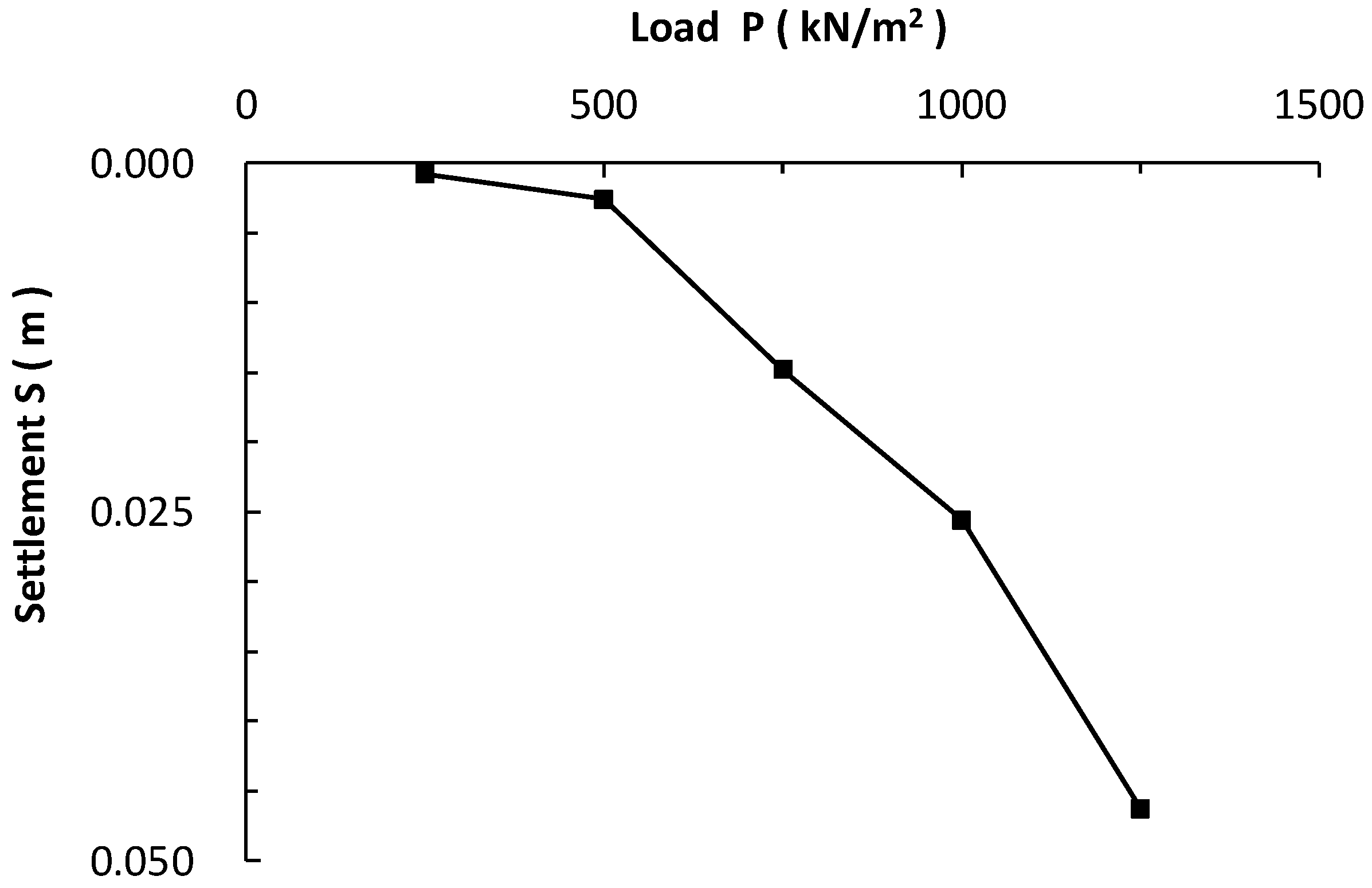
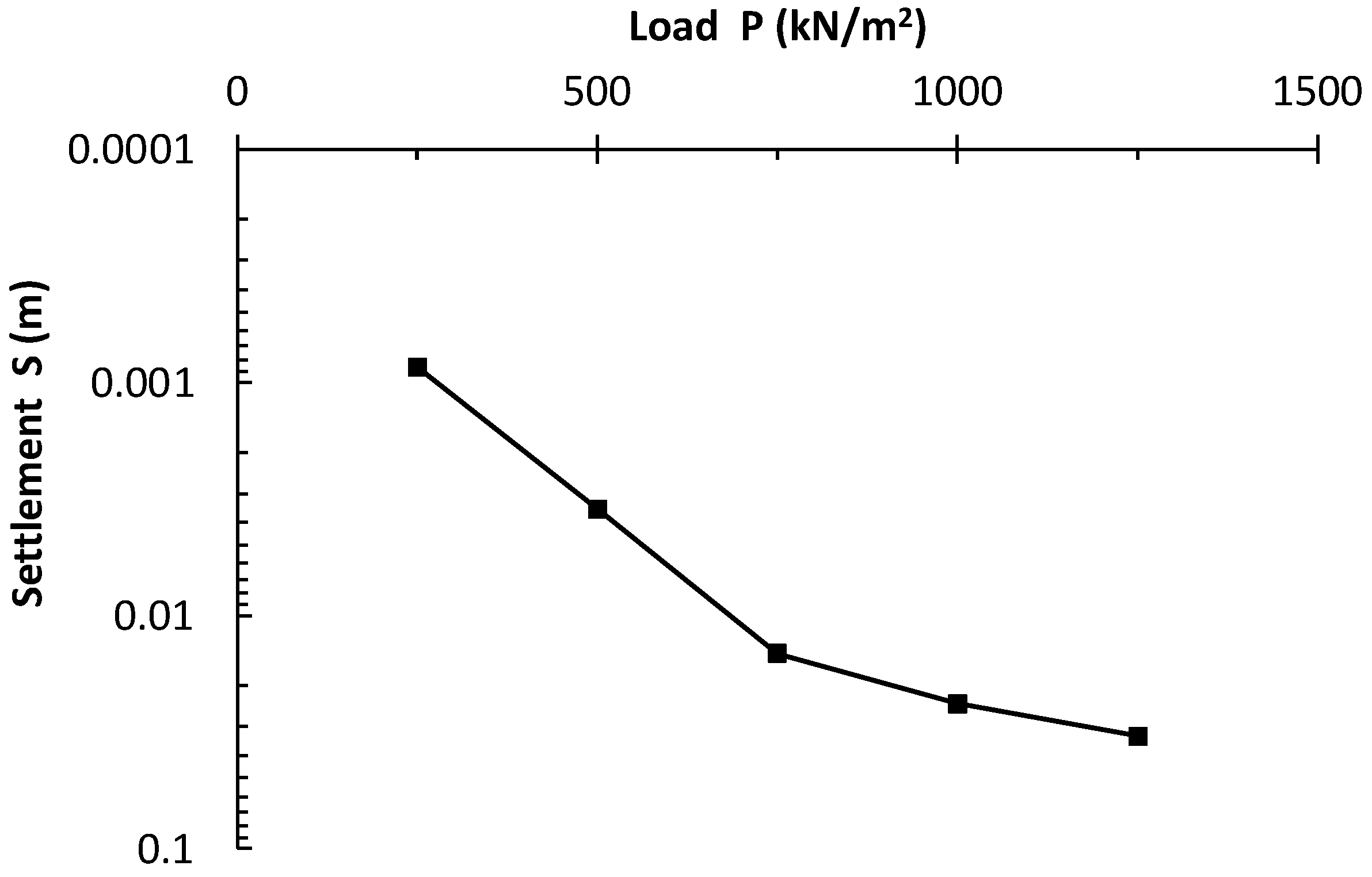
3.2.1. Flat-Plate Loading Test

In the flat-plate loading test, a small steel plate (load plate) is placed in an excavation to the depth where the foundation is to be placed, and a load corresponding to the weight of the actual building is applied to measure the amount of settlement to determine the safe bearing capacity of the soil [22,23]. The purpose of this test is to assess the resistance of LSS to failure and collapse under loading. The test method used is JGS 1521, the “Flat-plate Loading Test Method for Soil” [24].
The ultimate bearing capacity (kN/m2) can be obtained from the load and settlement of the steel plate, allowing for the determination of the deformation and bearing capacity characteristics of the ground required for construction. Using the results of load and settlement, the coefficient of subgrade reaction force, k v s , can be calculated from Equation (1):
k v s = Δ P Δ S = P 2 P 1 S 2 S 1
where k v s is the coefficient of ground reaction force (kN/m3) in the case of stepped loading, P 1 and P 2 are the load (kN/m2), and S 1 and S 2 are the respective settlement (m), except that P 1 is assumed to be unloaded (load 0) and P 2 is 1/3 of the load in principle [25].

3.2.2. Screw Weight Sounding Test

A rod with a screw point attached to its tip is loaded and screwed into the ground, and the number of rotations required to screw it in by 0.25 m is measured [26]. The purpose of this test is to determine whether the LSS meets the requirements for roadbeds and road bodies based on the converted CBR values [27].
The converted N value can be obtained from the applied load and the number of half turns per meter, N s w . The long-term allowable stress can be determined using Equation (2), and the unconfined compressive strength q u i (kN/m2) can be obtained from Equation (3). Using the unconfined compressive strength, the in situ CBR (%) and indoor CBR (%) can be calculated using Equations (4) and (5) [26].
Long term   allowable   stress = 30 + 0.6 N s w
q u i = 45 + 0.75 N s w
In   situ   C B R = 0.075 × q u i q u * × 100
Indoor   C B R = 0.062 × q u i q u * × 100
where i is the number of days of material age (days) and q u * is the standard strength (=100 kN/m2) [26].

3.2.3. Unconfined Compression Test

The unconfined compression test is a test in which an unconfined compressive load is gradually applied to a cylindrical specimen until the specimen fails while allowing it to expand laterally. Unconfined compressive strength is an important indicator of the quality of HFLSS made of RCS with respect to its fracture behavior. The purpose of this test is to determine whether HFLSS made of RCS meets the quality requirements of LSS.
The unconfined compressive strength can be determined by plotting the stress–strain relationship obtained from this test. The coefficient of deformation, E 50 (kN/m2), can be calculated using Equation (6):
E 50 = q u / 2 ε 50 × 100
where ε 50 is the axial strain (%) at a compressive stress of q u / 2 [27].

3.2.4. Consolidation Test

Loads are applied to the specimens described in “Specimens Used in Mechanical Tests”, and consolidation is performed in a short period of time. The amount of settlement is measured at each elapsed time from the start of loading, and the relationship between the rate of settlement and the elapsed time can be shown [25,28]. This test is conducted to determine the quality of LSS in terms of compressive settlement.

3.2.5. Flow Test

Flow tests were conducted using the specimens described in “Specimens Used in Mechanical Tests” [29]. The test method was based on the test method for air-mixed mortar and air-mixed milk (JHS A 313-1992; ϕ0.08 m and h0.08 m air cylinders were used). This test can be used to determine the flowability of LSS.

4. Results of Mechanical Tests

4.1. Flat-Plate Loading Test

Flat-plate loading tests were conducted on a specimen as described in “Specimens Used in Mechanical Tests”. The coefficient of subgrade reaction force obtained from this test is explained by comparing the shear stress acting on the plastic slip surface with the shear strength of the soil, as shown in the bearing capacity theory [4]. Figure 5 shows the load–settlement curve at 28 days of age. To find the ultimate bearing capacity, which is not as evident as shown in Figure 5, it is necessary to identify the point where the curve drops sharply and becomes almost parallel to the axis of settlement or the point where the increase in settlement becomes significant and the settlement starts to increase linearly. However, there is no such inflection point in Figure 5. It is also challenging to determine the ultimate bearing capacity from the logarithm of the settlement in Figure 6. Therefore, the load at the point of 10% settlement of the loading plate diameter (0.03 m) is taken as the ultimate bearing capacity, which is 1026 kN/m2 at 28 days of material age. The maximum settlement is 0.046 m at 28 days of material age. By using Equation (1) based on this value and Figure 5, the coefficient of subgrade reaction force is 2.2 × 10⁴ kN/m3.

4.2. Screw Weight Sounding Test

The screw weight sounding test was conducted on a specimen as described in “Specimens Used in Mechanical Tests”, and the CBR values were obtained by converting the results. The CBR value obtained from this test is an index required when using HFLSS made of RCS for the roadbed [25,30]. However, there is an abnormal value of 750.0 kN/m2 for the long-term allowable stress at a penetration depth of 0.80 m (see Table 4). This discrepancy is because the allowable stress exceeds the measurable range of the screw weight sounding tester. In other words, the long-term allowable stress in this test is considered to be 222 kN/m2, and the unconfined compressive strength can be confirmed to be 285 kN/m2 by substituting the number of half-turns per meter at this depth into Equation (3). From this value, the in situ CBR was determined to be 21.4% based on Equation (4) and the indoor CBR was determined to be 17.7% based on Equation (5). The difference between the indoor and on-site CBRs can be attributed to the site conditions and the boundary conditions of the soil. LSS is nearly saturated, and excess pore water pressure is generated and dissipated as a result of deformation when a load is applied. The main cause of the difference is the generation of excess pore water pressure.

4.3. Unconfined Compression Test

Unconfined compression tests were conducted on each of the five specimens with the same combination described in “Specimens Used in Mechanical Tests”: two at 7 days of material age and three at 28 days of material age. Unconfined compressive strength is an important indicator of the strength of LSS [4]. Figure 7 shows the change in the shape of the stress–strain curve for each of the three specimens with the same combination at 28 days of material age. The unconfined compressive strength is at the top of the convex part of the curve, and Figure 7 shows that the average strength is 515 kN/m2 at 28 days of material age. By substituting the values into Equation (6), the authors obtain an average deformation coefficient of 101 kN/m2.

4.4. Consolidation Test

Each of the three specimens with the same combination as described in “Specimens Used in Mechanical Tests” were used in the consolidation test. Figure 8 shows the average amount of settlement to the initial state of the specimen. It can be observed that there is almost no change in the rate of settlement after 1 min since the start of loading. Additionally, the change was approximately 0.8% by the end of 1000 min (the rate of settlement after 1 min was about 20.8%, and after 1000 min, it was 21.6%). Therefore, it is expected that the same rate of settlement will continue to be maintained after 14 h.

4.5. Flow Test

Flow tests were conducted on each of the three specimens with the same combination described in “Specimens Used in Mechanical Tests”. The flow test results are shown in Table 5 as the average value. The flow value of the LSS is 0.44 m and that of the HFLSS made of RCS is 0.54 m. LSS with a flow value of 0.30 m or more can be pumped to achieve high filling performance. In other words, all of the LSSs exhibit high flowability. HFLSS made of RCS has even higher flowability. Therefore, it is anticipated that low pumping pressure can be used for construction and high filling performance can be achieved.

5. Discussion for Mechanical Tests

LSS can be used as a backfill material as well as a fill material. The following considerations should be taken into account when designing the strength of the backfill material [4]. The quality of HFLSS made of RCS must satisfy the following conditions:
(1)
The self-weight or load should not cause fracture or compressive settlement of the LSS (unconfined compressive strength should be higher than the deviator stress that occurs when soil overburden pressure is applied to the LSS);
(2)
The required strength of the roadbed must be satisfied;
(3)
Re-excavation should be possible (when re-excavation is assumed to be necessary due to backfilling of buried pipes, etc., care should be taken so that re-excavation will not be difficult due to excessively high strength);
(4)
Proper load transmission should be ensured.
Table 6 presents the test results of HFLSS made of RCS in mechanical tests and the values of mechanical properties of conventional LSS [4]. The conventional LSS, which is referred to as SF in the engineering classification of geomaterials, exhibits a wet density of 1870 kg/m3, a dry density of 1400 kg/m3, and a pore ratio of 1.01.
Comparisons are made between HFLSS made of RCS and conventional LSS according to Table 6. The unconfined compressive strength of conventional LSS is 1000 kN/m2 at 28 days of material age, whereas that of HFLSS made of RCS reaches a maximum of 515 kN/m2. This difference is attributed to the high flowability of HFLSS made of RCS. The low unconfined compressive strength is accompanied by low coefficients of subgrade reaction and CBR values of 2.7 × 10⁵ kN/m3 (40–70%) for conventional LSS and 2.2 × 10⁴ kN/m3 (17.7%) for HFLSS made of RCS. The values for HFLSS made of RCS are 2.2 × 10⁴ kN/m3 and 17.7%. However, the unconfined compressive strength required for ordinary backfilling is 100–300 kN/m2 or higher in most cases, indicating that HFLSS made of RCS meets the necessary quality [4,5,6,7,8,9]. On the other hand, both the coefficient of subgrade reaction and CBR values are low, raising concerns about deformation. However, the CBR values are significantly higher than the values specified for roadbed materials by the Japan Expressway Public Corporation and the Civil Aviation Bureau of the Ministry of Land, Infrastructure, Transport, and Tourism, suggesting that the material can be used as a road material [25]. Nonetheless, attention must be paid to land use after reclamation due to its susceptibility to deformation.
Normally, the standard flowability of LSS used for backfilling and cavity filling is a flow value of 0.14 m or more, taking pumping and workability into consideration. When backfilling with LSS that retains normal flowability, pumping LSS with a flow value of 0.30 m or more is said to provide very high filling performance when filling and finishing very narrow voids left after backfilling with LSS, which retains normal flowability. On the other hand, the flow value of HFLSS made of RCS is 0.54 m, which is higher than that of conventional LSS. HFLSS made of RCS with a flow value of 0.54 m can fill even narrower gaps than the flow value of 0.30 m, making it suitable for filling spaces with complex structures. Therefore, HFLSS made of RCS can be used not only for finishing but also as backfill or filling material, and it can be expected to provide high filling performance at lower pumping pressure.
Regarding the particle size of the parent material of each LSS, both LSS and HFLSS made of RCS have a wide range of properties. This means that it is difficult to control the silt and clay content of the parent material in detail. However, the parent material for HFLSS made of RCS is a dewatered stock solution with a maximum particle size of 74 μm or less for the fine grains.
The flow value comparison in Table 5 shows that the HFLSS made of RCS has higher flowability than the LSS. The reason for the higher flowability of HFLSS made of RCS is its lower specific gravity. The difference in specific gravity and plastic viscosity between HFLSS made of RCS and LSS may be due to the particle size distribution, as the maximum particle size of the dewatered stock solution of each LSS is different from that of the LSS.

6. Conclusions

In this study, mechanical properties and flowability were investigated to develop HFLSS made of RCS. The following are the results obtained:
(1)
The mechanical properties of HFLSS made of RCS were lower than those of conventional LSS;
(2)
The unconfined compressive strength required for ordinary backfilling is 100–300 kN/m2 or higher in most cases, and HFLSS made of RCS meets the required quality;
(3)
HFLSS made of RCS can be used not only for finishing but also as backfill or filling material, and it can be expected to provide high filling performance at lower pumping pressure;
(4)
The reason for the higher flowability of HFLSS made of RCS is its lower specific gravity;
(5)
HFLSS made of RCS is superior to conventional LSS in long-distance pumping and installation in complex spaces.
The advanced development of LSSs in this study expects to promote recycling construction-generated soils, including construction-generated sludges in the construction industry. It is necessary to investigate the volume shrinkage and bleeding of HFLSS made of RCS in the future.

Author Contributions

Conceptualization, S.I. and S.N.; methodology, S.I.; software, S.I.; validation, Y.S. and S.C.; formal analysis, Y.S. and S.C.; investigation, Y.S.; resources, Y.S.; data curation, S.I. and S.N.; writing—original draft preparation, S.C.; writing—review and editing, S.I. and S.N.; visualization, S.I.; supervision, S.I.; project administration, S.I.; funding acquisition, S.I. and S.N. All authors have read and agreed to the published version of the manuscript.

Funding

This research received no external funding.

Institutional Review Board Statement

Not applicable.

Informed Consent Statement

Not applicable.

Data Availability Statement

Data are contained within the article.

Conflicts of Interest

The authors declare no conflict of interest.

References

  1. Nilimaa, J. Smart materials and technologies for sustainable concrete construction. Dev. Built Environ. 2023, 15, 100177. [Google Scholar] [CrossRef]
  2. Grebenkov, D.S. Depletion of resources by a population of diffusing species. Phys. Rev. E 2022, 105, 054402. [Google Scholar] [CrossRef] [PubMed]
  3. Wada, Y.; van Beek, L.P.H.; van Kempen, C.M.; Reckman, J.W.T.M.; Vasak, S.; Bierkens, M.F.P. Global depletion of groundwater resources. Geophys. Res. Lett. 2010, 37, L20402. [Google Scholar] [CrossRef]
  4. Public Works Research Institute; LSS Method Engineering Consultants Inc. Manual for Utilization of Liquefied Stabilized Soil, 2nd ed.; Gihodo Shuppan Co., Ltd.: Tokyo, Japan, 2007. [Google Scholar]
  5. Inazumi, S.; Kaneko, M.; Tomoda, Y.; Shigematsu, Y.; Shishido, K. Evaluation of flow-ability on fluidization treated soils based on flow analysis by MPS method. Int. J. GEOMATE Geotech. Constr. Mater. Environ. 2017, 12, 53–58. [Google Scholar] [CrossRef]
  6. Inazumi, S.; Kaneko, M.; Shigematsu, Y.; Shishido, K. Fluidity evaluation of fluidisation treated soils based on the moving particle semi-implicit method. Int. J. Geotech. Eng. 2018, 12, 325–336. [Google Scholar] [CrossRef]
  7. Inazumi, S.; Shigematsu, Y.; Nakao, K.; Shishido, K. 3-D particle flow analysis for fluidization treated soils. Am. J. Civ. Environ. Eng. 2018, 3, 59–67. [Google Scholar]
  8. Le, H.K.; Kohata, Y. Strength and deformation properties of liquefied stabilized soil prepared by various conditions. Int. J. GEOMATE Geotech. Constr. Mater. Environ. 2020, 23, 179–188. [Google Scholar] [CrossRef]
  9. Cui, Y.; Kohata, Y.; Liu, W. Influence of cement solidification agent and slurry density on mechanical property of liquefied stabilized soil. Int. J. GEOMATE Geotech. Constr. Mater. Environ. 2020, 19, 177–184. [Google Scholar] [CrossRef]
  10. Ministry of Land, Infrastructure, Transport and Tourism. Results of the Construction Byproduct Sustainability Survey in 2018 (Signalized Values) Reference Materials; Ministry of Land, Infrastructure, Transport and Tourism: Tokyo, Japan, 2018; pp. 1–5. [Google Scholar]
  11. Sakai, S. Municipal solid waste management in Japan. Waste Manag. 1996, 16, 395–405. [Google Scholar] [CrossRef]
  12. Hird, M.J.; Lougheed, S.; Rowe, R.K.; Kuyvenhoven, C. Making waste management public (or falling back to sleep). Soc. Stud. Sci. 2014, 44, 441–465. [Google Scholar] [CrossRef]
  13. Komine, H.; Watanabe, Y. The past, present and future of the geo-environment in Japan. Soils Found. 2010, 50, 977–982. [Google Scholar] [CrossRef]
  14. Yoshida, H.; Shimamura, K.; Aizawa, H. 3R strategies for the establishment of an international sound material-cycle society. J. Mater. Cycles Waste Manag. 2007, 9, 101–111. [Google Scholar] [CrossRef]
  15. Nozaki, N.; Lu, K.; Singh, R.K.; Mizunoya, T.; Yabar, H.; Higano, Y. Simulation analysis of policy for waste treatment toward a sound material-cycle society in Tokyo. J. Sustain. Dev. 2017, 10, 65. [Google Scholar] [CrossRef]
  16. Johnson, O.A.; Napiah, M.; Kamaruddin, I. Potential uses of waste sludge in construction industry: A review. Res. J. Appl. Sci. Eng. Technol. 2014, 8, 565–570. [Google Scholar] [CrossRef]
  17. Raheem, A.; Sikarwar, V.S.; He, J.; Dastyar, W.; Dionysiou, D.D.; Wang, W.; Zhao, M. Opportunities and challenges in sustainable treatment and resource reuse of sewage sludge: A review. Chem. Eng. J. 2018, 337, 616–641. [Google Scholar] [CrossRef]
  18. Oladejo, J.; Shi, K.; Luo, X.; Yang, G.; Wu, T. A review of sludge-to-energy recovery methods. Energies 2018, 12, 60. [Google Scholar] [CrossRef]
  19. Hadi, P.; Xu, M.; Ning, C.; Lin, C.S.K.; McKay, G. A critical review on preparation, characterization and utilization of sludge-derived activated carbons for wastewater treatment. Chem. Eng. J. 2015, 260, 895–906. [Google Scholar] [CrossRef]
  20. Takei, Y. Current state and future prospects of countermeasures to soil contamination. Sci. Technol. Trends 2010, 4, 55–67. [Google Scholar]
  21. Kermani, M.; Ebadi, T. The effect of oil contamination on the geotechnical properties of fine-grained soils. Soil Sediment Contam. Int. J. 2012, 21, 655–671. [Google Scholar] [CrossRef]
  22. Villaescusa, E. Geotechnical Design for Sublevel Open Stoping, 1st ed.; Routledge: Abingdon-on-Thames, UK, 2014. [Google Scholar]
  23. Liu, J.; Tian, Y.; Orton, S.L.; Said, A.M. Resistance of flat-plate buildings against progressive collapse. I: Modeling of slab-column connections. J. Struct. Eng. 2015, 141, 04015053. [Google Scholar] [CrossRef]
  24. White, D.J.; Vennapusa, P.; Roesler, J.R.; Vavrik, W. Plate load testing on layered pavement foundation system to charac-terize mechanistic parameters. In Proceedings of the Geo-Congress 2019: Geotechnical Materials, Modeling, and Testing 2019, Philadelphia, PA, USA, 24–27 March 2019; pp. 214–226. [Google Scholar]
  25. The Japanese Geotechnical Society. Japanese Geotechnical Society Standards: Geotechnical and Geoenvironmental Investigation Methods (Volume 2); The Japanese Geotechnical Society: Tokyo, Japan, 2015. [Google Scholar]
  26. The Japanese Geotechnical Society. Japanese Geotechnical Society Standards: Geotechnical and Geoenvironmental Investigation Methods (Volume 1); The Japanese Geotechnical Society: Tokyo, Japan, 2015. [Google Scholar]
  27. The Japanese Geotechnical Society. Japanese Geotechnical Society Standards: Laboratory Testing Standards of Geomaterials (Volume 2); The Japanese Geotechnical Society: Tokyo, Japan, 2015. [Google Scholar]
  28. The Japanese Geotechnical Society. Japanese Geotechnical Society Standards: Laboratory Testing Standards of Geomaterials (Volume 1); The Japanese Geotechnical Society: Tokyo, Japan, 2015. [Google Scholar]
  29. Kang, G.; Cikmit, A.A.; Tsuchida, T.; Honda, H.; Kim, Y.S. Strength development and microstructural characteristics of soft dredged clay stabilized with basic oxygen furnace steel slag. Constr. Build. Mater. 2019, 203, 501–513. [Google Scholar] [CrossRef]
  30. Talukdar, D.K. A study of correlation between California Bearing Ratio (CBR) value with other properties of soil. Int. J. Emerg. Technol. Adv. Eng. 2014, 4, 559–562. [Google Scholar] [CrossRef]
Figure 1. Pumping of underground space.
Recycling 08 00067 g001
Figure 2. Backfilling of the retaining wall.
Recycling 08 00067 g002
Figure 3. Flow of intermediate processing of construction sludges.
Recycling 08 00067 g003
Figure 4. Particle size distribution curves.
Recycling 08 00067 g004
Figure 5. Relationship between load and settlement in the plate-loading test (28 days).
Recycling 08 00067 g005
Figure 6. Relationship between load and logarithm settlement in the plate-loading test (28 days).
Recycling 08 00067 g006
Figure 7. Relationship between stress and strain in the unconfined compression test (28 days).
Recycling 08 00067 g007
Figure 8. Change in subsidence ratio.
Recycling 08 00067 g008
Table 1. Survey on actual situation of construction by-products conducted in 2018.
Construction By-Product20082018Construction Recycling Promotion Plan 2014
Target Value for 2018Target Value Achieved
Recycling rate of asphalt and concrete lumps98.4%99.5%99% or moreAchieved
Recycling rate of concrete mass97.3%99.3%99% or moreAchieved
Rate of recycling and reduction of wood wastes from construction89.4%96.2%95% or moreAchieved
Rate of recycling and reduction of mixed construction wastes39.3%63.2%60% or moreAchieved
Effective utilization rate of construction-generated soils71.7%79.8%80% or moreUnachieved
Table 2. Detailed combination of HFLSS made of RCS used for mechanical tests.
HFLSS Made of RCS
Wet density (kg/m3)1.143
Undiluted solution of slurry (m3)1.00
Cementitious solidifier (kg/m3)150
Maximum grain size (μm)74
Table 3. Detailed combination of LSSs used for flow test.
LSSHFLSS Made of RCS
Stock specific gravity1.2101.143
Cementitious solidifier (kg/m3)150150
Water content (%)62.0267.55
Maximum grain size (μm)over 7474
Table 4. Results of the screw weight sounding test.
Load, Wsw (kN)Half Rotation Speed, NaPenetration Depth, D (m)Penetration Amount, L (m)Half-Turn Per
1 m, Nsw
Convention
N Value
Long-Term Allowable Stress (kN/m2)
0.05 0.050.05 0.20.1
0.15 0.050.00 0.50.7
0.25 0.060.01 0.81.9
0.50 0.070.01 1.57.5
0.75 0.080.01 2.316.9
1.00 0.090.01 3.030.0
1.00110.250.16696.571.4
1.00470.500.2518812.4142.8
1.00800.750.2532019.0222.0
1.00600.800.05120063.0750.0
Table 5. Results of the flow test.
LSSHFLSS Made of RCS
Flow value (m)0.440.54
Table 6. Results and general values of LSSs.
HFLSS Made of RCSConventional LSS
Material age (days)28728
Unconfined compressive strength (kN/m2)285–515over 500over 1000
Modulus of subgrade reaction (kN/m3)2.2 × 1042.7 × 105
CBR (lab. test) (%)17.740–70
CBR (site) (%)21.4over 40–70
Disclaimer/Publisher’s Note: The statements, opinions and data contained in all publications are solely those of the individual author(s) and contributor(s) and not of MDPI and/or the editor(s). MDPI and/or the editor(s) disclaim responsibility for any injury to people or property resulting from any ideas, methods, instructions or products referred to in the content.

