Review

Neutron Imaging in Cultural Heritage Research at the FRM II Reactor of the Heinz Maier-Leibnitz Center

1
Heinz Maier-Leibnitz Center, Technische Universität München; Lichtenbergstr. 1, 85748 Garching, Germany
2
School of Geography, Archaeology and Environmental Studies, University of the Witwatersrand, Private Bag 3, Johannesburg WITS 2050, South Africa
3
Science and Technology Facilities Council (STFC), ISIS Neutron and Muon Source, Didcot OX11 0QX, UK, [email protected]
4
Consiglio Nazionale delle Ricerche (CNR), Istituto dei Sistemi Complessi (ISC), Sesto Fiorentino via Madonna del Piano 10, 50019 Roma, Italy
5
Department of Palaeoanthropology and Messel Research, Senckenberg Research Institute Frankfurt/Main, Senckenberganlage 25, 60325 Frankfurt am Main, Germany
6
Department of General Zoology, Faculty of Biology, Universität Duisburg-Essen, Universitätsstr. 5, 45117 Essen, Germany
7
Bavarian Research Institute of Experimental Geochemistry and Geophysics (BGI), University of Bayreuth, Universitätsstraße 30, 95447 Bayreuth, Germany
8
Senckenberg Center for Human Evolution and Palaeoenvironment (HEP), Eberhard Karls Universität, Sigwartstr. 10, 72074 Tübingen, Germany
9
Laboratoire AMIS, UMR 5288, Université Toulouse III—Paul Sabatier, 118 Route de Narbonne, 31062 Toulouse, France
*
Author to whom correspondence should be addressed.
J. Imaging 2018, 4(1), 22; https://doi.org/10.3390/jimaging4010022
Submission received: 30 October 2017 / Revised: 6 December 2017 / Accepted: 21 December 2017 / Published: 14 January 2018
(This article belongs to the Special Issue Neutron Imaging)

Abstract

:
Neutron Imaging is ideally suited for applications in cultural heritage even at small reactors with moderate image resolution. However, recently, high resolution imaging is being increasingly used for advanced studies, especially in paleontology. The special contrast for hydrogen and between neighboring elements in the periodic system allows for new applications that are not accessible for X-rays, like organic material in enclosed containers made of ceramics or metals, fossilized bones in chalk rock or in ferrous “red” beds, and even for animal and hominid teeth. Fission neutrons permit the examination of large samples that otherwise show large attenuation for thermal neutrons.

1. Introduction

X-ray scanners are available in many museums and research centers, so they are always first choice for the examination of cultural heritage objects. However, X-rays fail when metal objects with organic matter inside (e.g., religious relics), or bones in chalk rock or even when ferrous clastic terrestrial deposits (“red beds”) need to be examined. Neutrons also deliver a contrast between many neighboring elements in the periodic system, often rendering contrast between very similar materials like enamel and dentine in fossil teeth. Cold neutrons are employed at the ANTARES facility, and fission neutrons are available at the NECTAR facility to penetrate large samples. An overview about neutron methods in cultural Heritage is given in [1].

2. The Neutron Imaging Facilities

2.1. The Antares Facility

After a redistribution of beamlines and dismantling of the first ANTARES facility in 2010, the new ANTARES facility went into operation in 2013 at the FRM II research reactor of the Technische Universität München [2].
The facility operates on one channel (of two) of the cold neutron beamline SR4 at the FRM II reactor, being the only cold neutron imaging facility at a reactor with direct sight to the cold source with neutron flight tubes instead of neutron guides, so neutrons travel on a straight flight path and do not lose collimation and spectral homogeneity by reflection on neutron guides. The unusual shape (Figure 1) is caused by its position relative to the reactor building outer wall and the neighboring instruments. After completion of the neighboring neutron guide, the shielding between beams close to the reactor will be too thin to allow access when the drum shutter in the biological shielding for both beams is open.
Therefore, ANTARES has its own experimental shutter, and a collimator drum for six different collimation rates. The first chamber on the left houses beam forming devices like the additional fast shutter, a velocity selector, a double crystal monochromator, and grating for neutron grating interferometry. Due to high scattered radiation from these devices, it is not accessible for the users during operation. The middle and the right chamber contain sample and detector positions for small and for large samples.
The peculiar shape of the shielding required a separating wall to carry the roof, so two separate chambers were installed for small samples in front and for large samples in the back, where the beam has expanded more. Samples up to 15 cm in size are usually measured in the small chamber, larger samples up to 30 cm in the large chamber.

2.2. The Nectar Facility

The NECTAR facility uses an Uranium converter plate in front of a beam tube (Figure 2a,b) to generate fission neutrons that can enter the beam tube unmoderated [4]. The converter plate consists of 2 slabs of highly enriched uranium (93% 235U)-silicide with a total weight of 540 g. The highly energetic fission neutrons with a spectrum with mean energy at about 1.8 MeV have high penetration power giving more insight into large samples. On the other hand, due to the high energy, the detection process itself is limited in spatial resolution to about 0.5 mm. The first chamber of the beamline (MEDAPP) is dedicated to medical treatment of cancer patients, the second chamber (NECTAR) is used for fast neutron imaging (Figure 2a). The converter plate can be moved out of the beam, so the beamline can also be used for thermal neutron imaging after removal of thermal neutron filters [5].
Due to the possibility of automatic switching between fission and thermal spectra, NECTAR can be used for a broad variety of applications. The non-destructive testing by means of combined thermal and fast neutron imaging performed without moving the sample can provide complementary information about the investigated objects. The high penetration depth of fission neutrons allows us to gain information about the inner structure of large objects and samples containing strongly attenuating elements. In contrast, the spatial resolution achievable with thermal neutrons is comparable with cold neutron imaging, while the penetration depth of thermal neutrons is still higher than in the case of cold neutrons available at ANTARES.

3. Neutron Computed Tomography with Thermal and Cold Neutrons

3.1. Fossils Embedded in Breccia Rock

A band of limestone caves spans half the African continent. When roofs collapse, the resulting holes in the ground above become death traps for humans and animals alike. Dripping water with chalk and falling pebbles form a conglomerate of bones, pebbles and limestone. X-ray contrast between bones and chalk rock is rather small for X-rays, but significant for neutrons. While awaiting the construction of the new neutron imaging facility at the South African Nuclear Energy Corporation (Necsa), some fossil samples from the Ditsong Museum of Natural History in Pretoria were examined at the ANTARES facility.
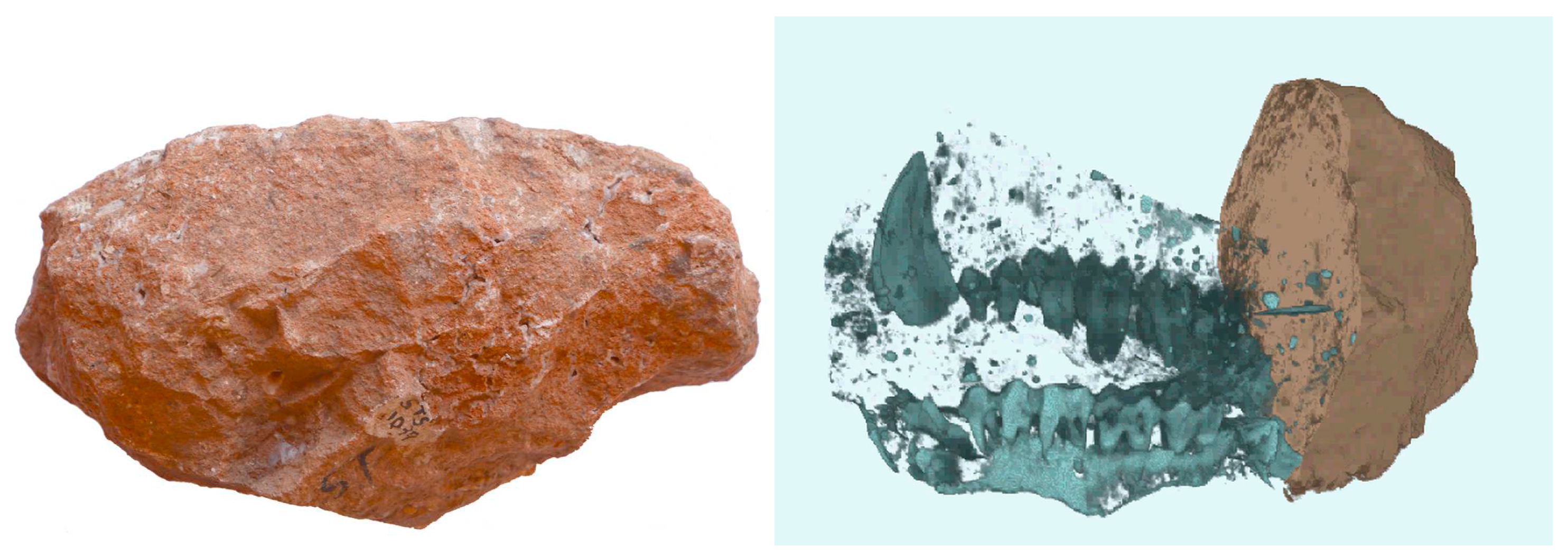
A fist-sized rock (Figure 3a) had no visible external features except for a few traces of bone at the surface. Neutron computed tomography (N-CT) revealed a nearly complete set of teeth from an upper jaw, with the skull itself missing (Figure 3b). Following data elaboration, the segmentation and examination of all individual teeth allowed for the attribution to Cercopithecoides williamsi, an extinct primate species [8].
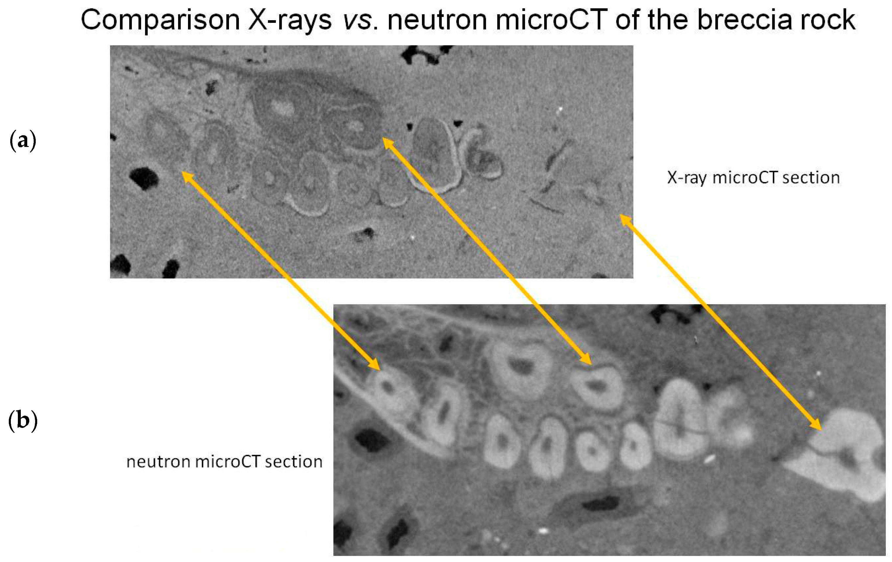
Figure 4a,b shows a comparison of later performed X-ray CT and N-CT of the same object. Contrast is much more significant for neutrons.

3.2. Fossilized Teeth—Human or Ape?

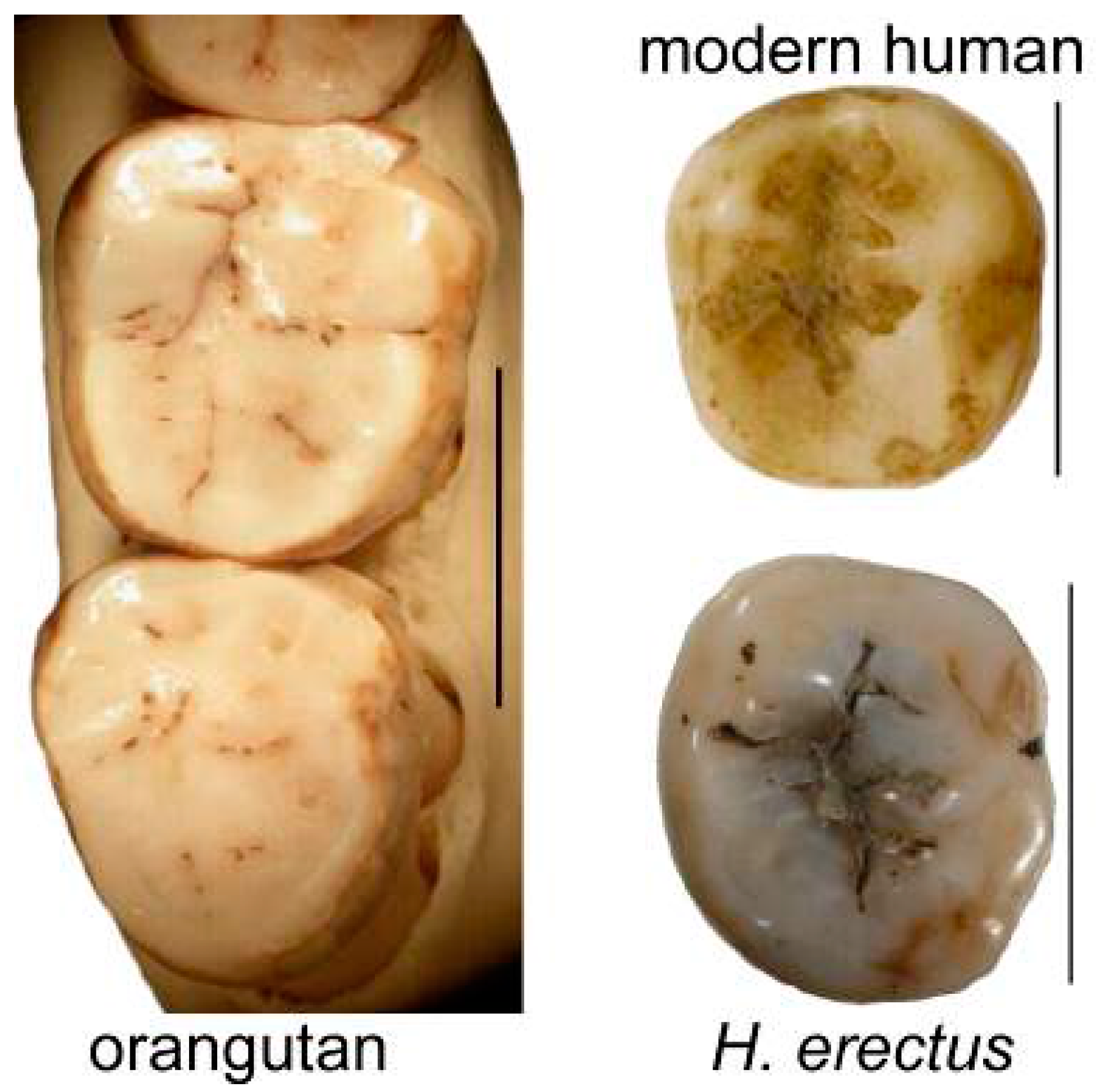
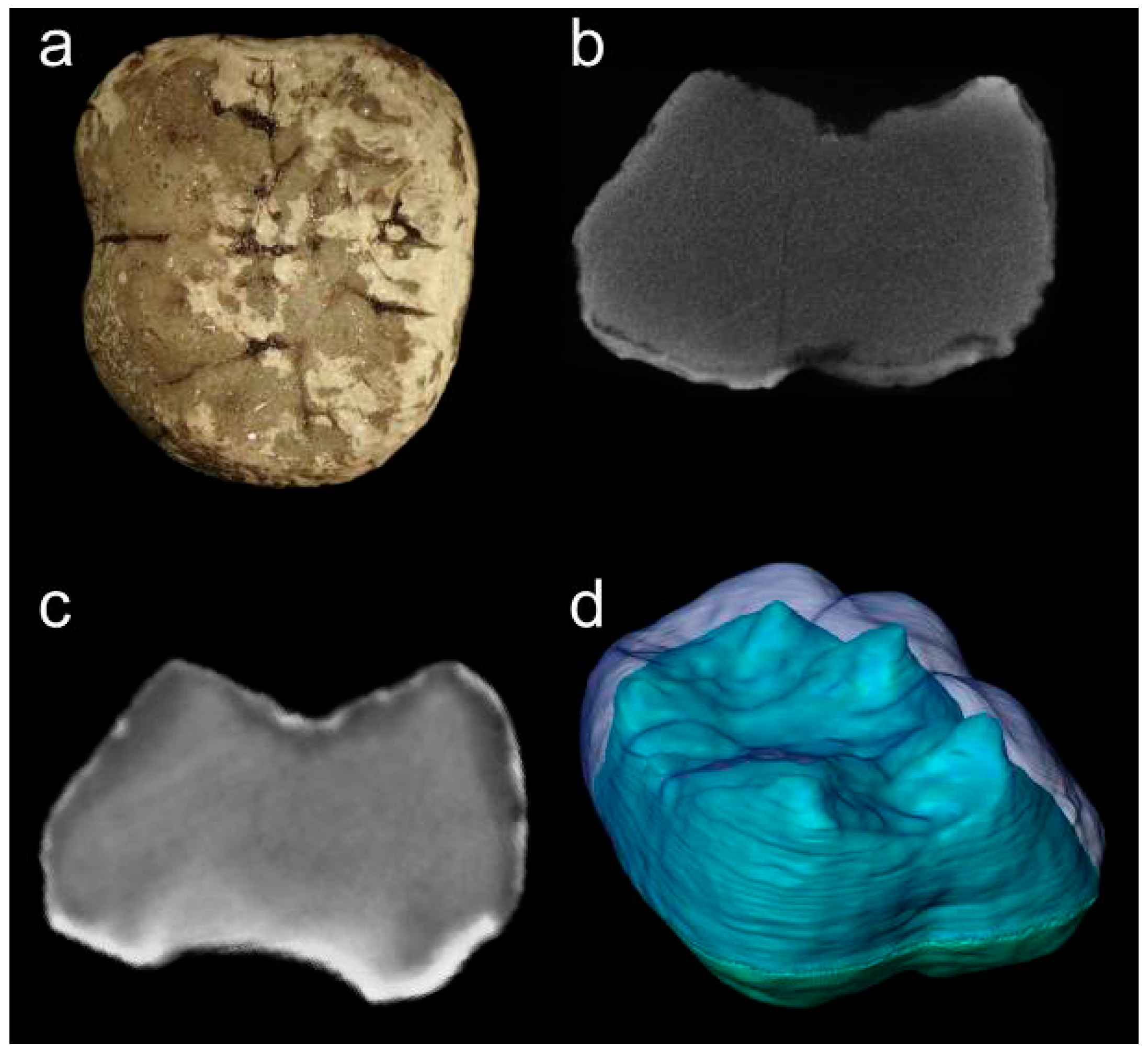
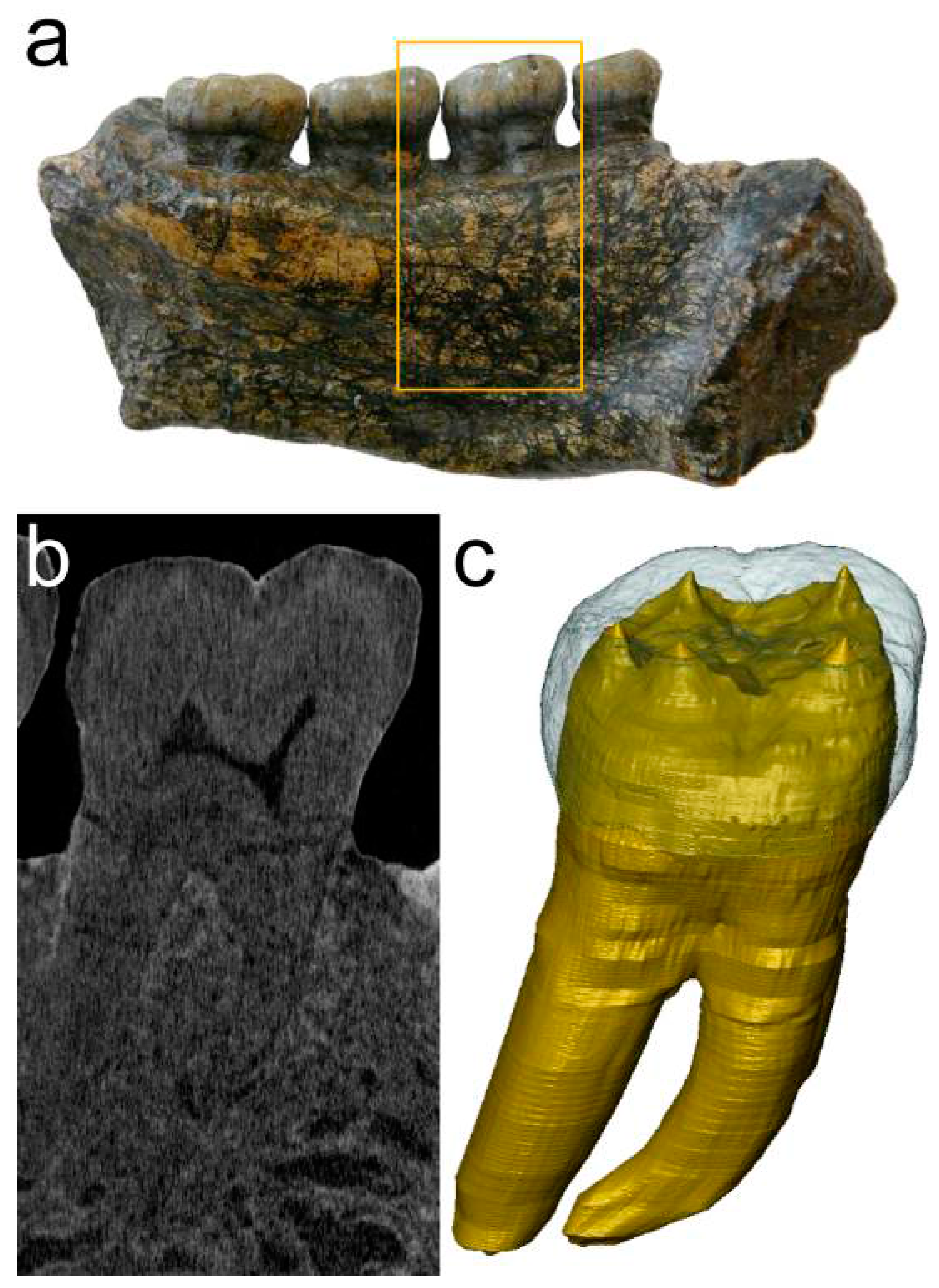
There has been an ongoing discussion for several decades whether some of the hominid teeth found in Indonesia should be attributed to a relative of orangutans, or to an early human species, Homo erectus. The outer surface of even slightly worn teeth does not give sufficient information for diagnostic discrimination (Figure 5) [9], but the interface between enamel and dentine is different for both species. Human teeth have higher relief of the dentine whereas it is more flat and squat in orangutans [10]. The interface can be visualized with synchrotron radiation for some specimen, but remains invisible for others. Current assumptions attribute this absence of contrasts to a mineral exchange that happens during fossilization and/or to a change of physical properties of the dental tissues, depending on the geological environment. The exact nature of the process is yet unknown and may be examined with Prompt Gamma Activation Analysis in the future. Compared with X-ray microtomography (X-µCT), Neutron micro-computed tomography (N-µCT) shows a distinct interface between dentine and enamel in all cases (Figure 6). The Senckenberg Museum Frankfurt and the University of Toulouse examined several sets of teeth at ANTARES [11], enabling discriminating between orangutan and human specimens, even for heavily mineralized teeth that delivered more noisy data, because transmission through the densely mineralized mandible was very low in longitudinal direction (Figure 7).

3.3. Hearing Capabilities of the Mammalian “Forerunners” Therapsida

Before the emergence of the dinosaurs, the Therapsida were the dominant group of vertebrates on land, i.e., from the Mid-Permian to the Late Triassic. As they are ancestral to mammals, studying therapsids may help to shed light on the origin of mammalian features. For example, at some point in synapsid evolution, warm-bloodedness and tympanic hearing evolved, along with increased brain capacity.
However, therapsid skulls are often found in iron-rich continental deposits, so-called “red beds”. Although the fossils were often prepared after excavation, most cavities inside the skulls such as the inner ear labyrinths, the nasal cavity and the braincase still remain filled with iron containing matrix that is often inaccessible for X-rays. Previous investigations have shown that neutron computed tomography is an ideal tool to study the internal structure of these skulls [12] and references therein.
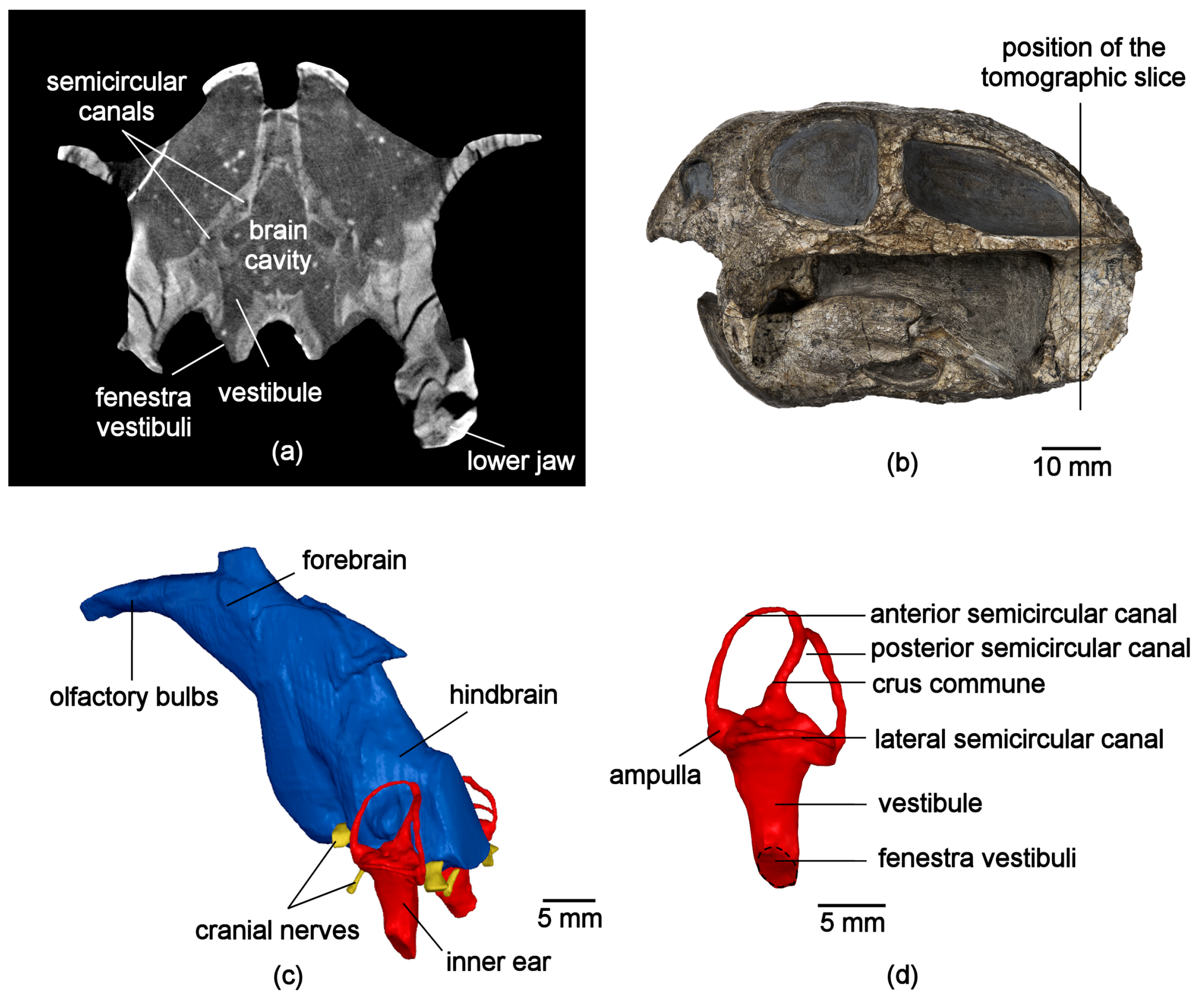
As soft tissue is not preserved, the anatomy of the sensory organs, the muscles and the vasculature can only be deduced from the shapes of the skull bones and from impressions of soft-tissue structures on the inner surfaces of the skulls. For example, N-CT images of a skull of Diictodon feliceps (Therapsida, Anomodontia) allowed for the reconstruction of the brain endocast and the inner ear labyrinth (Figure 8). The latter consists of two components: the vestibule for hearing and the semicircular canals for equilibrium. Remarkably, the vestibule of D. feliceps does not show a distinct cochlear cavity (Figure 8c,d, which is otherwise already present in some advanced therapsids and in mammals and might be an indication for a low sensitivity to airborne sound [13,14].

4. Neutron Computed Tomography with Fast Neutrons

Huge Fossils Examined at NECTAR

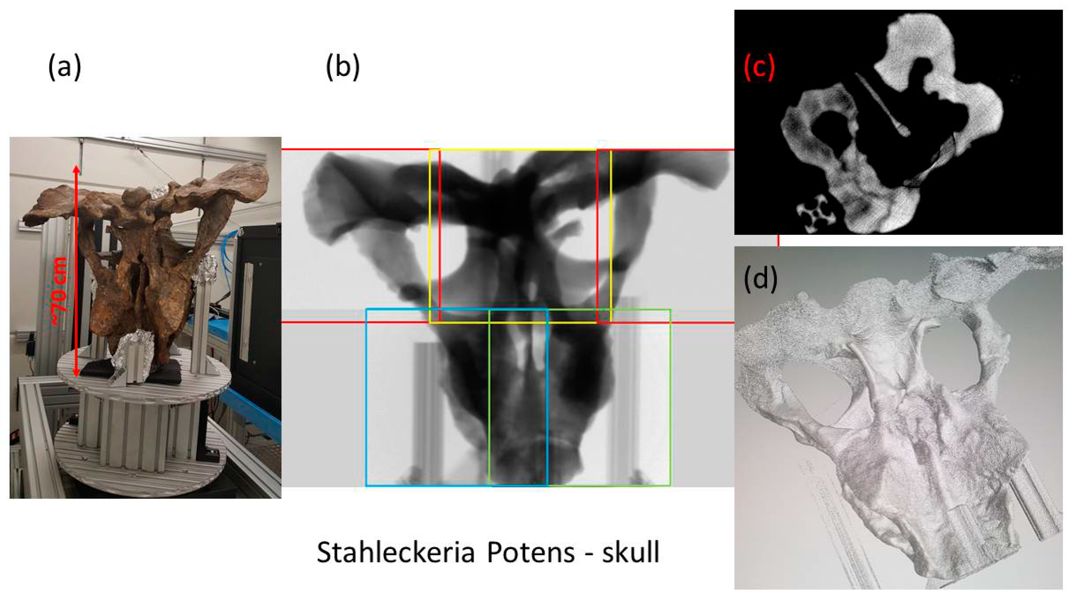
The huge skull of Stahleckeria potens (ca. 50 cm skull length), another therapsid species, was too big even for the NECTAR facility, but penetration was possible in all directions. The skull was recorded in sections that were stitched together to form single large radiographies. Computed tomography was calculated from the set of stitched angular views. This was the first time ever that such a large fossil was examined with fast neutrons at the NECTAR facility. This permits new research avenues for paleontology, where large specimens are currently CT-scanned only in medical facilities with a scan resolution of 3–6 mm on average.
Stahleckeria potens was one of the largest therapsids from the Mid-Triassic and similar in size as a hippopotamus. Recent cold neutron tomography of small therapsids skulls performed at ANTARES supported the hypothesis that a bony plate at the lower jaw of therapsids, the reflected lamina, served for sound detection [13]. A reflected lamina was also present at the lower jaw of S. potens, but it was extremely large and thick in comparison to small species. Consequently, the question arises how could this animal hear sound with such large bones. Therefore, the aim of our examination was to study the ear region of the skull and to reconstruct the hearing mechanism of this animal.
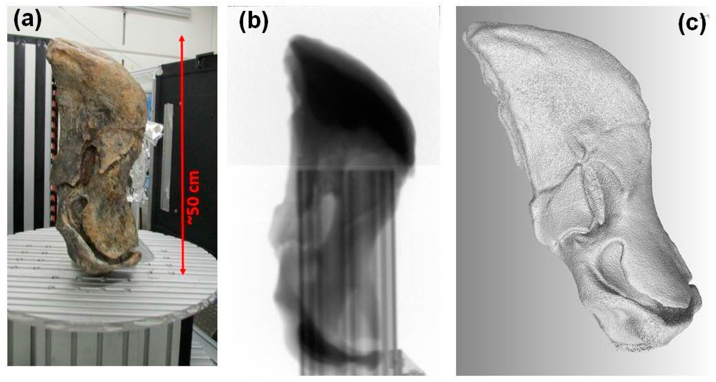
Neutron tomography can provide information required to address these questions; however, the inner structure in such large fossils is not accessible with cold neutrons available at ANTARES. Therefore, the lower jaw and the skull of S. potens were investigated at NECTAR facility. The first try of applying fission neutron imaging at NECTAR to paleontological studies is presented in Figure 9 and Figure 10.
The size of the studied samples was up to about 50 cm. Such large dimensions are easy to penetrate with fission neutrons; however, the examination of the samples was still challenging since the available field of view (FOV) at NECTAR was only 30 cm × 30 cm. As the sample dimensions exceeded the FOV, several images had to be taken for each projection angle during the tomography scan. In case of the tomography scan of the lower jaw, it was sufficient to measure two images per projection (Figure 9b). These two images were taken along the rotation axis, and therefore, it does not affect the further reconstruction. In fact, it is possible to reconstruct the two scans separately. Since the skull dimensions of S. potens exceeded the FOV in all directions (both parallel and perpendicular to rotation axis), a crucial step in the data processing was stitching of the images taken for each angle before the tomography reconstruction. In this case, five images per projection were recorded to cover the whole object (Figure 10b).

5. Energy Selective or Bragg Edge Imaging with Cold Neutrons

Metallurgic Examinations on Medieval Swords

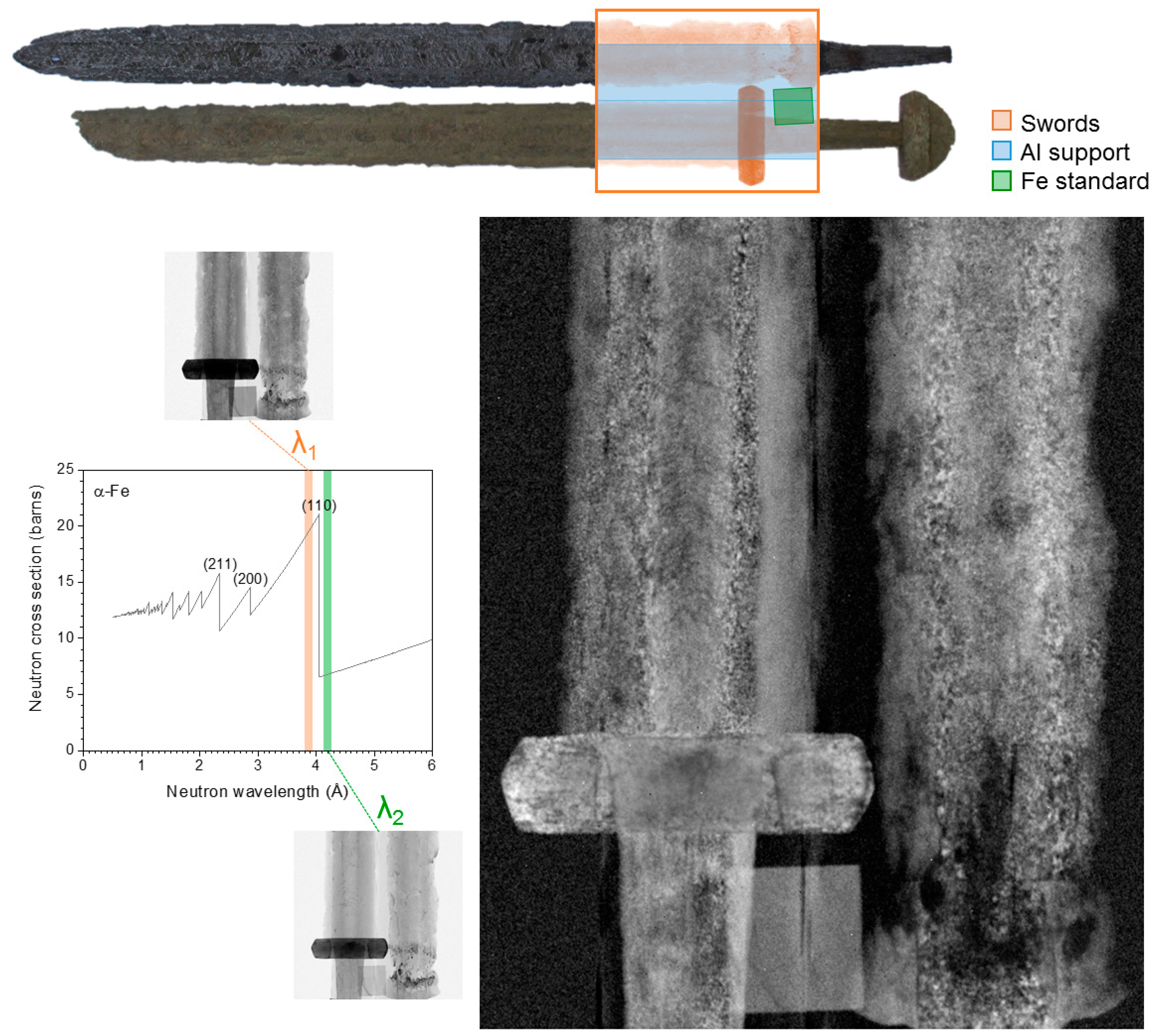
Thermal and cold neutrons may be absorbed by target nuclei, incoherently scattered by single nuclei (e.g., by Hydrogen), or may be scattered coherently by crystal structures. Interference patterns may arise if the wavelength is shorter than twice the lattice spacing in a crystal. If the wavelength is longer, coherent scattering is no longer possible, and the transmission rises suddenly at this wavelength of the so-called Bragg-Edge or Bragg Cutoff. At ANTARES, both a neutron velocity selector and a double crystal monochromator may be used to monochromatize the beam, and to perform wavelength scans. Different carbon content in smithing steel lets the steel assume different metallic phases with different forms of crystal lattices (ferrite, low carbon BCC phase and cementite, high carbon orthorhombic phase). To identify a specific metallic phase, neutron radiographies (or tomographies) are recorded of a sample with wavelengths above and below a characteristic Bragg cutoff for a specific phase, as the 110 Bragg edge of ferrite in the case of steel; with the wavelength longer than the characteristic cutoff, the neutron attenuation caused by coherent scattering in that phase disappears. Subtracting this radiography from a radiography with a shorter wavelength leaves only (or mostly, since absorption depends on the wavelength too) the features caused by the characteristic coherent scattering of that phase. The two wavelengths are in fact chosen as close as possible, so it is feasible to assume that the attenuation due to absorption is constant. This technique was used to examine different metallic phases on medieval swords and other weapons, revealing different carburization level, high and low temperature smithing and thermal treatment procedures. Figure 11 shows a transmission image of a section of two ‘pattern-welded’ Viking swords [15], made of composite rods of metal. The image reveals the distribution of ferrite (low carbon steel) with respect to the other phases (e.g., high carbon steel, slag inclusions). The grainy appearance of the blades is given by dark spots representing thermally affected grains showing the spatial distribution of the welding areas. In addition, this approach allowed us to identify an “L” shaped repair on one of the swords (see sword on the right in Figure 11), used for soldering the blade back to its handle with another alloy.

6. Conclusions

X-rays are always first choice for examinations for their easy availability and application. However, where X-rays fail or cannot deliver specific information, neutron imaging methods will be successful at most times, delivering contrasts and penetration data that are not accessible for X-rays. Neutron Imaging has now reached a level of image quality that nearly matches X-ray images. Scientific applications where results will be published are free at several high quality neutron imaging sites, while the Heinz Maier-Leibnitz Zentrum of Technische Universität München provides thermal/cold neutron imaging with the highest flux and resolution and the only fission neutron imaging facility worldwide. Applications for scientific beam time can be filed twice a year at [16].

Acknowledgments

Ms. Beaudet was supported by the Claude Leon Foundation and the Centre of Excellence in Palaeosciences. Ingmar Werneburg was supported by Schweizer Nationalfonds: SNF-grant P300PA_164720. FRM II measurements were supported by the European Commission under the 7th Framework Programme through the ‘Research Infrastructures’ action of the ‘Capacities’ Programme, NMI3-II Grant number 283883.

Author Contributions

Burkhard Schillinger: Whole text, esp. Section 1 and Section 2; Amélie Beaudet: Section 3.1; Ottmar Kullmer, Clément Zanolli: Section 3.2; Michael Laaß, Ingmar Werneburg: Section 3.3 and Section 4; |Malgorzata Makowska: Section 2.2 and Section 4; Anna Fedrigo, Francesco Grazzi: Section 5.

Conflicts of Interest

The authors declare no conflict of interest.

References

  1. Schillinger, B. Why use neutrons? Restaur. Archäol. 2015, 8, 1–7. [Google Scholar] [CrossRef]
  2. Schulz, M.; Schillinger, B.; Calzada, E.; Bausenwein, D.; Schmakat, P.; Reimann, T.; Böni, P. The new neutron imaging beam line ANTARES at FRM II. Restaur. Archäol. 2015, 8. [Google Scholar] [CrossRef]
  3. Schillinger, B.; Schulz, M. ANTARES Facility. Available online: http://mlz-garching.de/antares (accessed on 30 October 2017).
  4. Bücherl, T.; Söllradl, S. NECTAR: Radiography and tomography station using fission neutrons. J. Large-Scale Res. Facil. 2015, 1. [Google Scholar] [CrossRef]
  5. Mühlbauer, M.J.; Bücherl, T.; Genreith, C.; Knapp, M.; Schulz, M.; Söllradl, S.; Wagner, F.M.; Ehrenberg, H. The thermal neutron beam option for NECTAR at MLZ. Phys. Procedia 2017, 88, 148–153. [Google Scholar] [CrossRef]
  6. Kellermeier, M.; Bücherl, T.; Makowska, M. The NECTAR Facility. Available online: http://www.mlz-garching.de/instrumente-und-labore/bildgebende-verfahren-und-analyse/medapp-und-nectar.html (accessed on 30 October 2017).
  7. Converter Facility. Available online: http://www.frm2.tum.de/en/the-neutron-source/secondary-sources/converter-facility/ (accessed on 30 October 2017).
  8. Beaudet, A.; Braga, J.; De Beer, F.; Schillinger, B.; Steininger, C.; Vodopivec, V.; Zanolli, C. Neutron microtomography-based virtual extraction and analysis of a cercopithe oid partial cranium (STS 1039) embedded in a breccia fragment from sterkfontein member 4 (South Africa). Am. J. Phys. Anthropol. 2016, 159, 737–745. [Google Scholar] [CrossRef] [PubMed]
  9. Zanolli, C. Additional evidence for morpho-dimensional tooth crown variation in a new Indonesian H. erectus sample from the Sangiran Dome (Central Java). PLoS ONE 2013, 8. [Google Scholar] [CrossRef] [PubMed]
  10. Zanolli, C.; Grine, F.E.; Kullmer, O.; Schrenk, F.; Maccharelli, R. The early Pleistocene deciduous hominid molar FS-72 from the Sangiran dome of java, Indonesia: A taxonomic reappraisal based on its comparative endostructural characterization. Am. J. Phys. Anthropol. 2015, 157, 666–674. [Google Scholar] [CrossRef] [PubMed]
  11. Zanolli, C.; Schillinger, B.; Beaudet, A.; Kullmer, O.; Macchiarelli, R.; Mancini, L.; Schrenk, F.; Tuniz, C.; Vodopivec, V. Exploring hominin and non-hominin primate dental fossil remains with neutron microtomography. Phys. Procedia 2017, 88, 109–115. [Google Scholar] [CrossRef]
  12. Laaß, M.; Schillinger, B.; Werneburg, I. Neutron tomography and X-ray tomography as tools for the morphological investigation of non-mammalian synapsids. Phys. Procedia 2017, 88, 100–108. [Google Scholar] [CrossRef]
  13. Laaß, M. Bone conduction hearing and seismic sensitivity of the late permian anomodont Kawingasaurus fossilis. J. Morphol. 2014, 276, 121–143. [Google Scholar] [CrossRef] [PubMed]
  14. Laaß, M. The origins of the cochlea and impedance matching hearing in synapsids. Acta Palaeontol. Pol. 2016, 61, 267–280. [Google Scholar] [CrossRef]
  15. Fedrigo, A.; Strobl, M.; Williams, A.R.; Lefmann, K.; Lindelof, P.E.; Jørgensen, L.; Pentz, P.; Bausenwein, D.; Schillinger, B.; Kovyakh, A.; et al. Neutron imaging study of ‘pattern-welded’ swords from the Viking Age. Archaeol Anthropol Sci. 2016, 1–15. [Google Scholar] [CrossRef]
  16. Available online: http://www.mlz-garching.de/user-office (accessed on 20 December 2017).
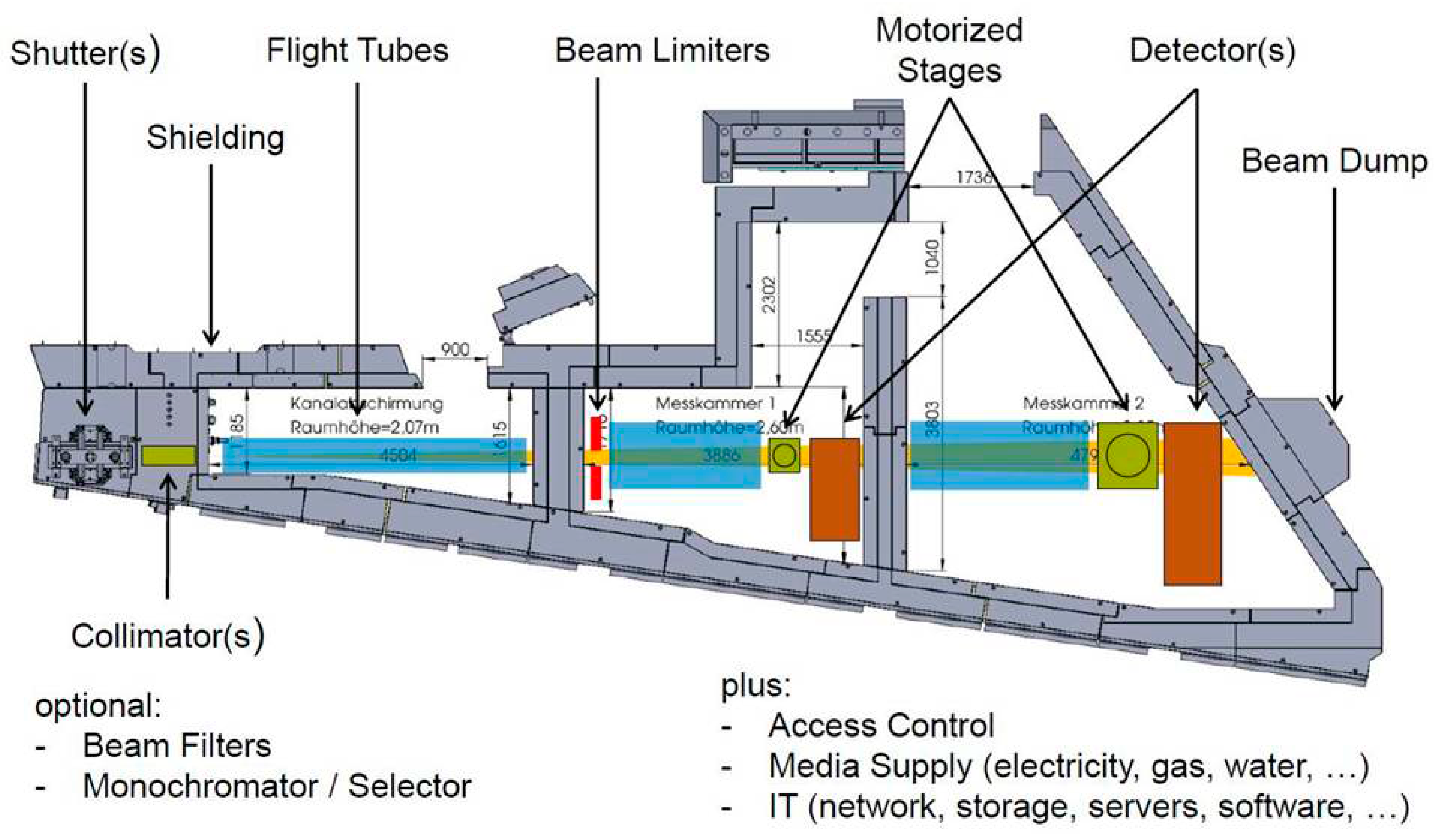
Figure 1. The ANTARES facility (modified from [3] with permission.).
Jimaging 04 00022 g001
Figure 2. The NECTAR facility, (a) shows a sketch of the beamline, (b) the enriched uranium converter plate position (from [6,7] with permission).
Jimaging 04 00022 g002
Figure 3. (a) Photo of the Breccia rock, left (b) Neutron computed tomography of the rock, right (photo by FRM II and original image).
Jimaging 04 00022 g003
Figure 4. (a,b) X-ray computed tomography (CT) and neutron computed tomography (N-CT) of the rock (Beaudet et al. 2016 [8], with permission).
Jimaging 04 00022 g004
Figure 5. When it is even slightly worn or damaged, the outer surface of hominid teeth gives no real clue for identification between orangutans and humans. The photo of the H. erectus molar is from [9] (open access), whereas all other illustrations are original pictures.
Jimaging 04 00022 g005
Figure 6. For some tooth specimens (a), X-CT slices sometimes fail to show contrasts between the mineralized tissues (b), whereas N-CT slices give a clear distinction between enamel and dentine (c), enabling reconstructing the 3D internal structure (d) [11] (with permission).
Jimaging 04 00022 g006
Figure 7. In mandibular specimens (a), due to fossilization, we sometimes obtained noisy datasets (b), but it was still possible to retrieve reliable morphological information on the internal tooth structure (c) [11] (with permission).
Jimaging 04 00022 g007
Figure 8. N-CT of the brain and ear region of Diictodon feliceps (collection of the Museum of Natural History in Berlin, number MB.R. 1000) (a), Tomographic slice through the ear region; (b), Photograph of the specimen showing the position of the tomographic slice; (c), 3D model of the brain endocast and the inner ears; (d), virtual reconstruction of the inner ear labyrinth (original figures).
Jimaging 04 00022 g008
Figure 9. Tomography studies of the lower jaw of Stahleckeria potens with a length of about 50 cm (Paleontological Collection of Universität Tübingen, number GPIT/RE/7106-2, examined at the NECTAR facility; (a) a photograph of the sample positioned at the sample stage; (b) a single projection (stitched two normalized radiographs); (c) 3D visualization of the reconstructed object (original pictures).
Jimaging 04 00022 g009
Figure 10. Tomography studies of the skull of Stahleckeria potens (GPIT/RE/7107) at the NECTAR facility; (a) photograph of the sample positioned at the sample stage; (b) a single projection (stitched five normalized radiographs); (c) a reconstructed tomography slice; (d) 3D visualization of the reconstructed object (original pictures).
Jimaging 04 00022 g010
Figure 11. Transmission image of a section of two ‘pattern-welded’ Viking swords (see diagram above for the position along the blade). Transmission images have been measured before (λ1) and after (λ2) the 110 ferrite Bragg edge, and by subtracting the two is was possible to obtain a transmission image enhancing the signal from ferrite [15] (original pictures).
Jimaging 04 00022 g011