
Gradient Micropillar Array Inspired by Tree Frog for Robust Adhesion on Dry and Wet Surfaces
by

Quan Liu
1,2,
Fandong Meng
1,
Di Tan
3,*,
Zhekun Shi
1,
Bo Zhu
1,
Kangjian Xiao
1 and
Longjian Xue
1,* 1
School of Power and Mechanical Engineering, The Institute of Technological Science, Wuhan University, South Donghu Road 8, Wuhan 430072, China
2
Institute of Special Polymer Research, Institute of Zhejiang University-Quzhou, 78 Jiuhua Roulevard North, Quzhou 324000, China
3
Institute of Textiles and Clothing, The Hong Kong Polytechnic University, Hung Hom, Kowloon, Hong Kong, China
*
Authors to whom correspondence should be addressed.
Biomimetics 2022, 7(4), 209; https://doi.org/10.3390/biomimetics7040209
Submission received: 17 October 2022
/
Revised: 10 November 2022
/
Accepted: 16 November 2022
/
Published: 21 November 2022
(This article belongs to the Section Biomimetics of Materials and Structures)
Abstract
:The strong adhesion on dry and wet surfaces and the durability of bioinspired hierarchical fibrillar adhesives are critical for their applications. However, the critical design for the strong adhesion normally depends on fine sub-micron structures which could be damaged during repeat usage. Here, we develop a tree frog-inspired gradient composite micropillars array (GP), which not only realizes a 2.3-times dry adhesion and a 5.6-times wet adhesion as compared to the pure polydimethylsiloxane (PDMS) micropillars array (PP), but also shows excellent durability over 200 repeating cycles of attachment/detachment and self-cleaning ability. A GP consists of stiffer tips and softer roots by incorporating gradient dispersed CaCO3 nanoparticles in PDMS micropillar stalks. The modulus gradient along the micropillar height facilitates the contact formation and enhances the maximum stress during the detaching. The study here provides a new design strategy for robust adhesives for practical applications in the fields of robotics, electronics, medical engineering, etc.
1. Introduction
To maximize the survival in the complex, dynamic natural environments, functional gradient structures have been developed in many creatures [1,2,3,4,5,6,7]. For instance, the microscale setae of the ladybird beetle Coccinella septempunctata have a gradient modulus from 7.2 GPa at the root to 1.2 MPa at the tip, endowing a high flexibility at the seta tip to enhance contact formation and a stiff stalk to maintain mechanical stability [6]. The same strategy of elastic modulus gradient has also been found in the hierarchical setae of gecko, which allows the nanoscale setal tip to form good contact with the counterpart surface, generating a strong adhesion of ~100 kPa [3,8]. Inspired by the modulus gradient in the setae of beetle/gecko, Hensel et al. [9] achieved similar adhesions on rough and smooth substrates by two-phase cylindrical pillars that were composed of a stiff stalk and a soft tip layer, which was prepared by sequenced casting. A smaller thickness of the top layer and a flat interface between the two phases are beneficial to the adhesion performances [10]. A gradually decreasing modulus from the pillar base to tip has also been incorporated into slanted micropillars which showed strong and anisotropic lateral friction forces [11].
Tree frogs, which can easily climb on vertical or even inverted dry/wet surfaces, have inspired the design of structured adhesives for dry and wet conditions [12,13,14,15,16,17]. Using a poly(acrylamide)/poly(vinyl alcohol) hydrogel to mimic the hexagonal epithelial cells in the tree frog, direct solid–solid contact has been suggested to play a major contribution to the wet adhesion [15]. Chen et al. [17] investigated the shape of epithelial cells on the toe pad of the tree frog Polypedates megacephalus and found the main shape was hexagonal. Inspired by this finding, stronger friction in the corner direction was demonstrated in slimmer polydimethylsiloxane (PDMS) hexagonal pillars. Meanwhile, Iturri et al. [13] showed higher friction forces in an elongated PDMS hexagonal pillar than regular hexagonal patterned or non-structured surfaces with/without water at the contact interface. By mimicking the densely packed and oriented hard keratin nanofibrils in tree frogs [18], Xue et al. [19] developed composite micropatterns that were composed of PDMS micropillars that were embedded with polystyrene nanopillars, showing improved adhesion and friction at the same time. Inspired by the nanoconcave top of epidermal cells on tree frogs’ toe pads, micropillar arrays with micropits [14] and nanoconcaves [20] on top have been designed and showed higher wet adhesion and friction compared to the arrays of micropillars with flat tops.
Meanwhile, it has been found that the keratinized layer on the toe surface has a modulus of 5–15 MPa, but the effective elastic modulus (Eeff) of the tissue beneath the keratinized layer continuously decreases to 4–25 kPa with the increase of depth in the toe pad [21], of which the modulus gradient is opposite as compared with the setae in geckos and beetles. The gradually softened interlayer maintains the integrity of the patterned epithelial cells, increasing the adaptability to surfaces, while the large Eeff on the surface is helpful for wear resistance [22]. The incorporation of the modulus gradient that is found in tree frogs into the gecko-inspired polydimethylsiloxane (PDMS) micropillar array with T-shape tips resulted in an enhancement of adhesion of 3.6-times [23]. It has been widely demonstrated that the micro- and nanopillar arrays with T-shape tips are the best structure design to gain strong normal adhesion for various materials [24,25]. Surprisingly, introducing the tree frog-inspired modulus gradient can even further enhance the adhesion performance of the T-shape micropillar array [23]. However, the preparation process of T-shape tips is rather complicated and the fine overhang structure in T-shape tips is rather soft and could be easily damaged during the repeating cycles of attachment/detachment, hindering the advance of T-shape adhesives toward practical applications [26]. Therefore, it is highly needed to simplify the design of micro- and nanopillar array adhesives and develop robust adhesives with prominent adhesion abilities and durability.
Here, we design a gradient composite micropillars array (termed as GP) with a modulus gradually increasing from the micropillar base to tip, mimicking the tree frog’s modulus gradient (Figure 1). The GP presents 2.3-times dry adhesion and 5.6-times wet adhesion as compared to the pure PDMS micropillars array (PP) with excellent durability. The softer base in the GP allows the pillar to adapt to the contacting surface easily, forming reliable contacts. The rigid tip increases the detaching stress and, therefore, enhances the force that is required for the separation. The concept of GPs and the fabrication method can be extended to other material combinations for strong adhesions.
2. Experimental Section
2.1. Materials
The polydimethylsiloxane (PDMS) elastomer kit (Sylgard 184) was purchased from Dow Corning (Michigan, MI, USA). Polyurethane (PU) resin (ST-1060 A/B) was purchased from BJB Enterprises, Inc., Tustin, CA, USA. CaCO3 was purc hased from Suzhou Research Materials Microtech Co., Ltd., Suzhou, China.
2.2. Equipment
SU-8 composed of arrays of micropillars were prepared by standard photolithography on lithography machine H94-37 (Sichuan Nanguang Nacuum Technology Co., Ltd., Chengdu, China). To obtain composite micropillars with a gradient distribution of CaCO3, centrifugations were carried out using an Eppendorf centrifuge 5810R, Germany. Surface microstructures were visualized by field emission scanning electron macroscopic (MIRA 3 LMH, Tescan AG, Brno, Czech Republic), a Nikon ECLIPSE Ci-L macroscopic, and 3D optical surface profiler (NewView 9000, ZYGO Corp., Middlefield, CT, USA). The elementary analyses were conducted by an energy-dispersive spectroscope (EDS) (X-Max 20, Aztec Energy, Oxford, England). The modulus of composite micropillars was tested on a Hysitron TriboIndenter system (Ti950, Hysitron Inc., Eden Prairie, MN, USA). Macroscopic adhesion was tested by a universal testing machine (Suns Tech UTM2103, Shenzhen, China). Microscopic adhesion tests were carried out on a home-made device with a 5 mm glass sphere as the probe.
2.3. Fabrication of Gradient Micropillars (GP)
GP was fabricated by a precise mold replication with the combination of gradient formation in the micropillars by actuation of centrifugal force in Figure 2a. Soft polyurethane (PU) molds containing patterned cylindrical cavities were replicated from SU-8 lithographic templates as previously reported (Figure 2(ai)) [20]. PDMS precursor that was mixed with CaCO3 NPs was filled into the PU mold by a vacuum-assisted capillary filling process, and the redundant PDMS/CaCO3-precursor composite on the PU mold was scraped away with a spatula (Figure 2(aii)). The PU mold that was filled with PDMS/CaCO3 viscous composites was then placed on a plastic Petri dish and transferred onto a swing-bucket centrifuge rotor, followed by the centrifugation at a predefined speed for a given period (Figure 2(aiii)). This centrifugation could generate a horizontal force along the axial direction of the cavities, which forces the CaCO3 NPs moving towards the bottom of the cavities in the PU mold and obtain a gradient distribution. The PDMS precursor was cast on the PU mold to create a 500 μm thick backing layer. The whole assembly was cured at 90 °C for 1 h. After the careful demolding from PU mold, the GP was ready (Figure 2(aiv)).
2.4. Fabrication of Homogeneous Composite Micropillars Array (HP)
HP was fabricated with the same procedures as GP, but without the centrifugation process.
2.5. Fabrication of Pure PDMS Micropillars Array (PP)
PP was fabricated by pouring pure PDMS precursor onto PU mold and cured at 90 °C for 1 h.
2.6. Nanoindentation
The modulus of PDMS/CaCO3 composite films was performed to calibrate the dependence of Eeff on ccal by quasi-static nanoindentation tests. Force-controlled nanoindentation tests with a maximum loading force of 100 μN were implemented in a Hysitron TriboIndenter system using a standard Berkovich probe (tip radius of ~100 nm) with a rate of 50 nm/s. For the PDMS/CaCO3 composite films, the tests were repeated (n = 5) at randomly selected spots on the surface. Elastic modulus values were obtained from the indentation load–depth curves based on the Oliver–Pharr method.
2.7. Adhesion Measurement
Macroscopic dry adhesion was tested by a universal testing machine. The substrate of the samples (6 × 6 mm) was fixed onto a smooth glass surface with the micropillar-array side facing upwards. A smooth metal plate was then placed on the micropillar array, and the metal plate formed full contact with the micropillar array under the gravity of the metal plate. The plate was separated from the array at a speed of 50 μm/s, and the maximum pull-off force was recorded, which was the macroscopic adhesion force. Macroscopic wet adhesion was tested by the same procedures as macroscopic dry adhesion, but with 1 mL of deionized water at the contact interface.
Microscopic dry adhesion performance was measured by a home-made device with a 5 mm glass sphere as the probe. The glass sphere probe approached the micropillars array with a velocity of 30 μm/s. At a certain displacement, the contact forms with the micropillars array. The probe was displaced into the micropillar array until a predefined loading force FL was reached. Then, the probe was retracted with the same velocity as it moved towards the micropillar array. The pull-off force Fad that represents the normal adhesion force of the micropillars array is the force that is required to separate the probe from the micropillar array. Fad has the opposite sign of FL. The adhesion and friction force were repeated 5 times and the mean value was calculated.
3. Results and Discussion
3.1. Construction of GP
The GP was fabricated by a soft lithography process [27,28], as shown in Figure 2a, and detailed in the experimental section. Briefly, the PDMS/CaCO3 mixture was spread onto the PU mold, and filled into the cavities by a vacuum-assisted capillary process (Figure 2(ai,ii)). CaCO3 nanoparticles (NPs) were chosen as the filler based on the following reasons: (1) CaCO3 is an abundant mineral, occupying 5% of the earth’s crust [29]; (2) the preparation of CaCO3 NPs is simple and the size is controllable; (3) CaCO3 NPs often serve as reinforcement to improve the mechanical strength of the polymer matrix [30,31]. Nearly 97% CaCO3 NPs possess a diameter less than 1 μm, which allows them to fill into the PU mold easily (Figure S1, Supporting Information). The excess mixture of PDMS/CaCO3 on the PU mold was carefully removed. Due to the larger density of CaCO3 NPs (2.9 g/cm3) than PDMS (1.1 g/cm3), the CaCO3 NPs were propelled towards the bottom of the cavities in the PU mold by applying a centrifugal force along the axial direction of the cavities (Figure 2(aiii)). The following coating of pure PDMS precursor on the mold and curing at 90 °C for 1 h resulted in the composite micropillars with a gradient-distributed CaCO3 NPs, which is termed as GP in the following text (Figure 2a and Figure S2, Supporting Information). For the controls, pure PDMS micropillars array (PP) and PDMS/CaCO3 homogeneous composite micropillars array (HP) were also fabricated in the same way, but without the addition of CaCO3 NPs or the centrifugation process, respectively. Due to simplicity of the methods, four different initial concentrations of CaCO3 NPs in PDMS precursor (ccal of 10, 30, 50, and 70 wt%) were used to regulate the Eeff of GP and HP. For convenience, the initial ccal is used to identify the samples, such as HP10wt% and GP10wt%, in the following text, although the exact ccal in the pillars could be different from the initial ones.
The resulting micropillars possess good physical integrity. The 3D images showed that the resulted GP, PP, and HP are 40 μm in diameter, 35 μm in height, and 80 μm in period (Figure 2b and Figure S3a,b, Supporting Information). Under dark-field illumination, the backing layer in GP (HP) is black, while the micropillars in GP are shining. It suggests the presence of CaCO3 NPs in the micropillars but not in the backing layer (Figure 2c). The SEM image clearly shows the presence and the gradually increased content of CaCO3 NPs from the base to the tip in the pillars of GP (Figure 2d). In contrast, the homogeneous distribution of CaCO3 NPs was found in HP (Figure S3c,e, Supporting Information) and no CaCO3 NPs in PP (Figure S3d,f, Supporting Information).
The gradient modulus of micropillars in GP was quantitatively characterized [32] (Figure 2e). In order to conveniently characterize the gradient, the micropillar was evenly divided into top, middle, and bottom layers along the micropillar height and the ccal of each layer was calculated based on the atom ratio of calcium to silicon. Clear gradient distributions of CaCO3 NPs in the three layers were detected in GPs, while a uniform distribution of CaCO3 NPs was found in HP (Figure S4, Supporting Information). Since the modulus of CaCO3 is much larger than that of PDMS (26 GPa vs. 2.2 MPa), the layer with the larger ccal possesses a larger Eeff (Figure S5, Supporting Information). Under the centrifugation at 3000 rpm for 5 min, Eeff of the top layer increased to 12.0 ± 0.9 MPa, while Eeff of bottom layer was 8.4 ± 1.3 MPa (Figure 2e). Increasing the centrifugation speed to 3900 rpm for 10 min, Eeff steeply increased to 16.0 ± 0.6 MPa in the top layer and decreased to 5.9 ± 0.1 MPa in the bottom layer, forming a distinct gradient in GP70wt% (Figure 2e). The increase in initial ccal, centrifugal speed and time increases the Eeff of the top layer and decreases the Eeff of the bottom layer. The modulus difference between the top and bottom layers divided by height is defined as the gradient rate (Figure 2f). For HP, the gradient rate is 0. The gradient rate of GP70wt% reached 101.4 kPa/μm under the centrifugation at 3000 rpm for 5 min and increased to 288.5 kPa/μm under 3900 rpm for 10 min. When the initial ccal was less than 50 wt%, GP can’t reach the largest gradient rate found in GP70wt% (Figure S6a,b, Supporting Information). However, the largest gradient rate of 387.7 kPa/μm was realized in the GP50wt% under a centrifugation at 3500 rpm for 10 min (Figure S6c, Supporting Information). It is assumed to be the result of a moderate viscosity of the mixture. Therefore, we can precisely regulate the gradient rate of the micropillars by combining ccal with the centrifugal parameters to mimic the gradient modulus that is found in tree frog toe pads [21].
3.2. Adhesion Performances
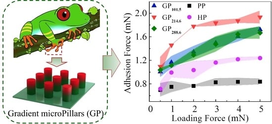
Adhesion performances of micropillars were conducted by macroscopic and microscopic tests. Samples (6 × 6 mm) were finger-pressed onto an upside-down glass surface and weight was hung beneath (Figure 3a). The GP could hold the highest weight of 45 g, much higher that on PP (29 g) and HP (32 g), which clearly suggests the advantage of the gradient modulus of GP in promoting adhesion abilities. Detailed examinations on the dependence of microscopic adhesion force, Fad, and the loading force (FL) were carried out on a home-made device with a 5 mm glass sphere as the probe (Figure S7, Supporting Information) [23]. A large FL can compensate the possible misalignment between the micropillars and the spherical probe, resulting in a better contact and, therefore, a larger Fad [20]. Thus, a higher Fad was detected under a larger FL (Figure 3b). For instance, the Fad of PP slight increased from 0.7 ± 0.1 to 0.8 ± 0.1 mN when FL was increased from 0.5 to 5.0 mN. In contrast, the Fad of GP214.6 (subscript indicates the gradient ratio) greatly increased from 1.1 ± 0.2 to 1.9 ± 0.1 mN, representing a 72.7% increase. The Fad of GP214.6 under FL of 5.0 mN is 122% and 61% higher than PP and HP, respectively. The GP with ccal of 10 wt%, 30 wt% and 50 wt% all showed enhancement in Fad, but the enhancement was less than GP with ccal of 70 wt% (Figure S8, Supporting Information). Thus, GP214.6 showed not only a much higher adhesion than PP and HP, but also a much stronger dependence on FL.
The dependence of Fad on the gradient rate (under FL = 5 mN) was further investigated (Figure 3c). The Fad of HP increased from 13.9 ± 0.8 to 21.3 ± 0.4 kPa while ccal increased from 0 to 70 wt%, which indicates a positive effect of increasing Eeff on the Fad. With ccal of 10 wt% and 30 wt%, the Fad slightly increased with the increase in gradient rate. At a ccal of 50 wt%, the Fad increased to 27.2 ± 1.1 kPa at gradient rate of 254.7 kPa/μm. When the initial ccal was set to 70 wt%, the Fad reached 31.9 ± 1.8 kPa at a gradient rate of 214.6 kPa/μm, which was 2.3-times the PP. The results further confirm that the enhanced adhesion originated from the modulus gradient. The further increase in the gradient rate (for instance, in GP288.6), however, reduced the Fad. The reduction in Fad could be the result of the large agglomeration in the pillars (Figure S9, Supporting Information), which may hinder the effective transfer of stress during the detachment. Furthermore, increasing the aspect ratio (AR) of micropillars could enhance the compliant ability of the micropillars to the counterpart surface and, therefore, the adhesion (Figure 3d) [33]. Therefore, the Fad of GP241.6 was 46.9% improved when AR was increased from 0.88 to 1.50 with the same ccal and centrifugal conditions. Interestingly, the adhesion enhancement in GP was also stronger than that of HP (28.1%) and PP (18.2%). As GP has no submicron structures, such as the overhangs in T-shape micropillars, GP241.6 has no notable decay in Fad after 200 macroscopic cycles test (Figure 3e), suggesting an extraordinary durability of the GP adhesive.
Macroscopic adhesion on a wet surface was also investigated (Figure S10, Supporting Information). As compared to the adhesion on the dry surface, wet Fad of GP was much smaller. A wet Fad of 5.8 ± 1.0 kPa was detected on GP214.6 with deionized water at the contacting interface (Figure 3f). It is reasonable as the captured liquid at the contacting interface hinders the effective formation of contact, reducing the adhesion. On the other hand, however, the wet Fad of GP214.6 remained the best as compared with PP and HP, which was 5.6- and 2.1-times the PP (1.0 ± 0.1 kPa) and HP (2.8 ± 0.4 kPa), respectively. Once again, it demonstrated the merits of the incorporation of modulus gradient in a micropillar array for adhesion enhancement, in both dry and wet conditions.
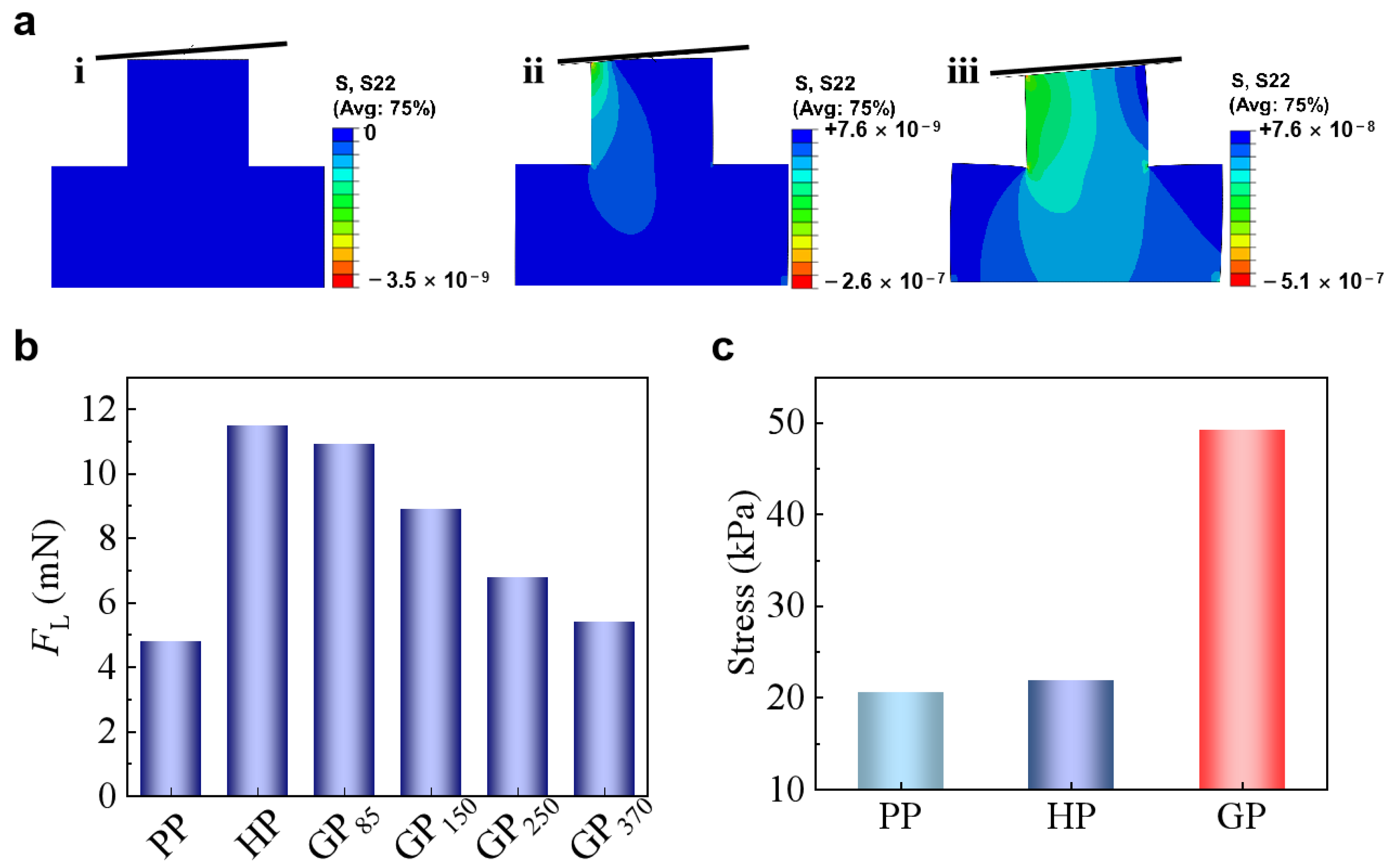
The gradient modulus in GP contributes to the adhesion enhancement based on two mechanisms. Gorb et al. [34] found a narrow neck beneath the contacting tip of the seta of the desert beetle Dytiscus marginalis and suggested that the narrow neck could reduce the local bending stiffness, making it easy to adapt to the misaligned surfaces. The soft root in GP could possess a similar function as the narrow neck. To demonstrate the concept, the approaching of a surface with tilting angle of 3° to the GP tip was finite element simulated (Figure 4a). When approached to a tilted surface, the micropillar bends to facilitate the contact formation [23]. While PP has the smallest Eeff and is the easiest to bend, it needs 4.8 mN to form full contact with the tilted surface (Figure 4b). In contrast, HP needs a much larger FL of 11.5 mN to form full contact. GP370 needs a FL of 5.4 mN to form the full contact, which is quite close to the FL that is required for PP. On the other hand, GP with a much larger gradient rate of 85 kPa/μm (GP85) could form full contact under a FL of 10.9 mN, which is similar to HP. In contrast, although GP also possess a large Eeff at the free end similar to HP, the soft root of GP increases its flexibility, enhancing the attaching ability to uneven or misaligned surfaces. The larger the gradient ratio, the smaller FL is needed for GP to adapt to the tilted surface (Figure 4b).
GP generates a larger stress maximum at the contact interface (σ), which is determined by the work of adhesion (W) and the effective modulus of the pillar tip (Eeff-tip) [35,36]:
where A is the area of the pillar end. As the detaching pairs are identical in all the cases here, W and A are constants. Therefore, the increase of Eeff-tip would increase the σ (Figure 4c), which means a larger force (Fad) is needed to separate the contacting pair. For instance, GP with Eeff-tip of 15 MPa has a σ of 50 kPa, which is almost 2-times of that in PP and HP. The easier contact formation and the larger stress that is required for detachment, therefore, generate the strongest adhesion on GP as compared with HP and PP.
3.3. Applications of GP
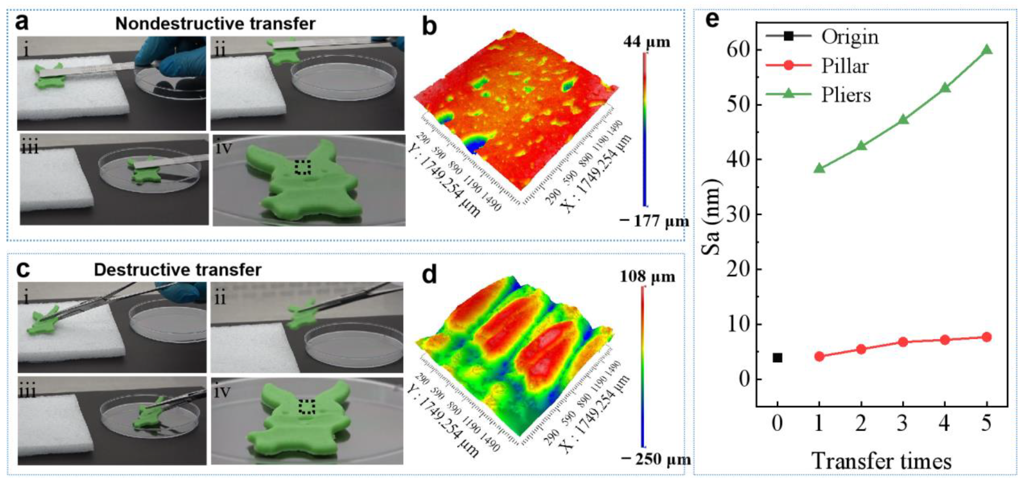
Undesirable damage occurring on the contact surfaces is a common phenomenon when grasping soft objects. In order to avoid this kind of damage, superior adhesion is in great demand on grasping soft objects [37]. Attempts to improve the adhesion performance on soft surfaces have mainly been pursued by the use of special adhesives or octopus-inspired sucker structures [12,37]. Since the soft objects are vulnerable, any excessive external force should be avoided. Therefore, it is highly desirable to develop a reusable adhesive pad with extraordinary adhesion ability with little external force. The strong adhesion of GP can solve this challenge perfectly. A soft plasticine toy with surface roughness (Sa) of 3.91 μm was used to demonstrate the concept (Figure S13, Supporting Information). The excellent adhesion of GP allows it stick to the surface of the soft plasticine toy by applying an ignorable FL. The higher adhesion under small FL makes GP capable of picking up an object with smaller FL as compared to PP and HP (Figure 3b). The subsequent peeling at a small angle can release the toy to a designated position easily (Figure 5a). The surface showed no clear deformation as compared to the surface before transportation (Figure 5b). In contrast, although a small force was carefully applied, sharp pliers grasping strongly deformed the surface, leaving bite marks on the surface (Figure 5c,d). After transferred by GP five times, the surface roughness of the soft plasticine toy slightly increased to 7.67 μm (Figure 5e). However, the surface roughness increased significantly to 59.88 μm after the transferring with the sharp pliers grasping five times.
3.4. Self-Cleaning Ability of GP
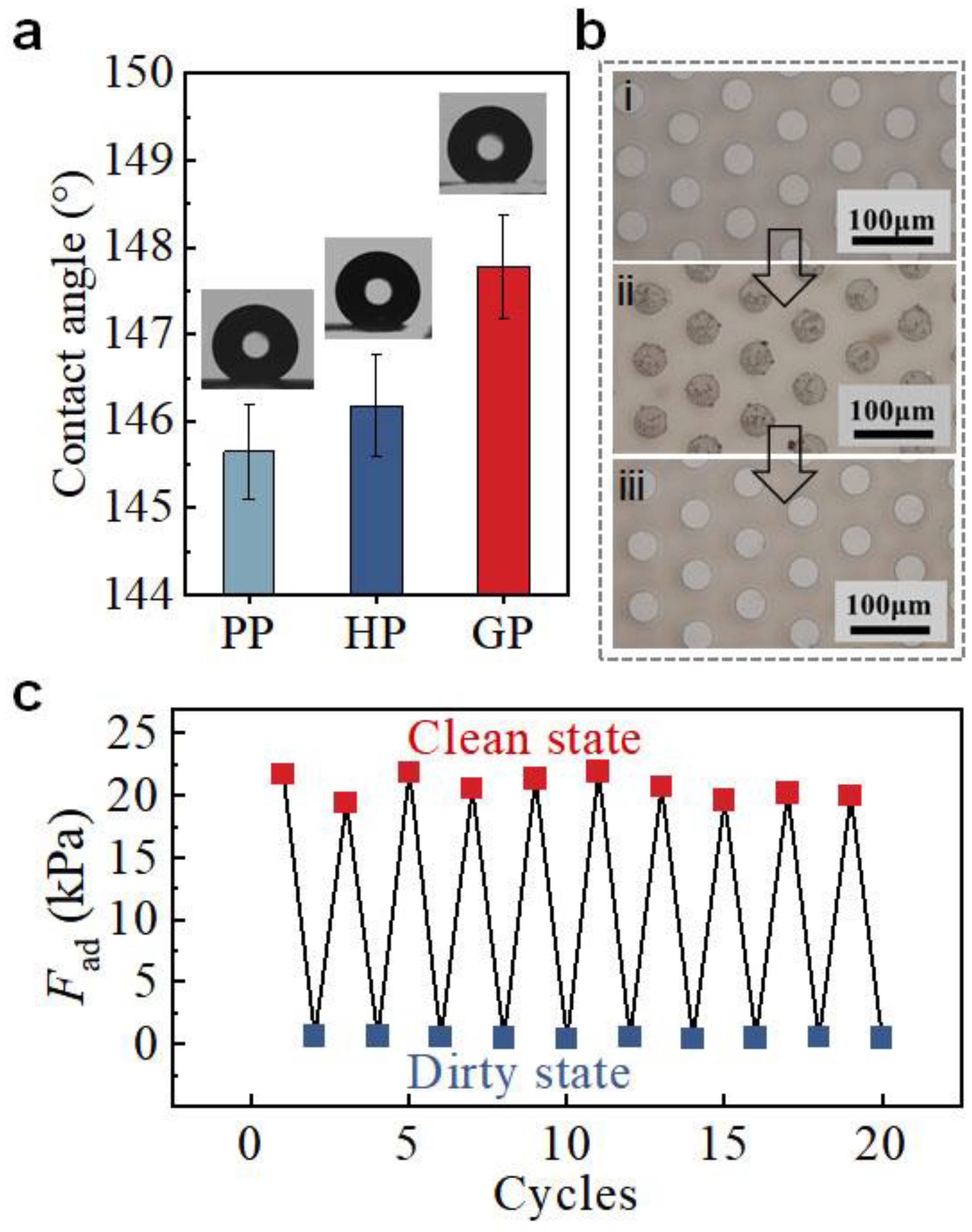
The self-cleaning ability is important for the re-usage of GP in dirty environments. The geometry of the micropillar array and the larger roughness on the pillar end of GP (Sa = 28.2 ± 4.9 nm, Figure S12) offer GP a water contact angle of 147.9 ± 0.9°, which is slightly larger than HP and PP (Figure 6a). The good hydrophobicity endows GP with self-cleaning ability [38]. With a simple flushing with water flow, GP can fully recover its adhesion ability after contamination by dust (Figure 6b). After 10 cycles of soiling and cleaning, the adhesion of GP remained unchanged (Figure 6c). It thus undoubtedly demonstrates the robustness of GP in dirty conditions and the ability of self-cleaning, which are of great significance to the reusability application of GP in real environments.
4. Conclusions
Inspired by the gradient modulus on the adhesive toe pad of tree frogs, a composite gradient micropillar array (GP) with a gradually increasing elastic modulus from the base to the tip along the micropillar height was successfully designed and constructed. The soft root of GP plays a similar role as the narrow neck structure of the desert beetle, which reduces the bending stiffness of GP and thus facilitates the contact with misaligned surfaces. The high modulus tip increases the maximum stress that is required for detaching, thus enhancing the adhesion. The slightly increased roughness on the pillar top of GP increased the hydrophobicity, which contributes the stronger adhesion in wet conditions and good self-cleaning ability. Thus, GP showed adhesion of 2.3- and 5.6-times compared to the pure PDMS micropillars array under dry and wet conditions, respectively. The results not only provide a robust material with strong dry and wet adhesion, which may find wide applications in various conditions.
Supplementary Materials
The following supporting information can be downloaded at: https://www.mdpi.com/article/10.3390/biomimetics7040209/s1, Figure S1: (a) SEM image of CaCO3 NPs. (b) The statistics of CaCO3 NPs’ diameters; Figure S2: SEM image of GP array; Figure S3: 3D images and height profile of (a) PP and (b) HP. Optical morphology of (c) PP and (d) GP. SEM images of cross sections of (e) PP and (f) HP; Figure S4: (a) Distribution of Ca elements in HP and GP; Figure S5: (a) The dependence of Eeff on ccal. Eeff of each layer in (b) GP10wt%, (c) GP30wt% and (d) GP50wt% under different centrifugal parameters; Figure S6: The gradient rate of (a) GP10wt%, (b) GP30wt% and (c) GP50wt% under different centrifugal parameters; Figure S7: (a) Home-made device for microscopic adhesion test. (b) Representative force-displacement curve measured on micropillar arrays with loading force (FL) and pull off force (adhesion force, Fad) indicated; Figure S8: Dependence of Fad of (a) GP10wt%, (b) GP30wt% and (c) GP50wt% on FL; Figure S9: SEM images of the cross section of GP70wt% with gradient rate of (a) 214.6 kPa/μm and (b) 288.6 kPa/μm; Figure S10: (a) Macroscopic wet adhesion test by using a universal testing machine. (b) Enlargement image of droplet water at the contact interface; Figure S11: Wet Fad of GP with different volume of water in the contact interface; Figure S12: Sa of various micropillars; Figure S13: (a) A photograph image of soft plasticine toy and (b) the 3D image with Sa of 3.91 μm.
Author Contributions
Experiment, writing—original draft preparation, formal analysis, data curation Q.L.; Experiment, F.M. and D.T.; visualization, Z.S. and B.Z.; review, K.X.; project administration, supervision, revision and funding acquisition, L.X. All authors have read and agreed to the published version of the manuscript.
Funding
This work was supported by National Natural Science Foundation of China (51973165), the Fundamental Research Funds for the Central Universities (2042022kf1220) and Research Funds of Institute of Zhejiang University-Quzhou (IZQ2021RCZX037).
Data Availability Statement
The data presented in this study are available upon request from the corresponding author.
Acknowledgments
We acknowledge the nanofabrication assistance from Center for Nanoscience and Nanotechnology at Wuhan University.
Conflicts of Interest
The authors declare no conflict of interest.
References
- Dong, X.; Zhao, H.; Li, J.; Tian, Y.; Zeng, H.; Ramos, M.A.; Hu, T.S.; Xu, Q. Progress in bioinspired dry and wet gradient materials from design principles to engineering applications. iScience 2020, 23, 101749. [Google Scholar] [CrossRef] [PubMed]
- Liu, Z.; Meyers, M.A.; Zhang, Z.; Ritchie, R.O. Functional gradients and heterogeneities in biological materials: Design principles, functions, and bioinspired applications. Prog. Mater. Sci. 2017, 88, 467–498. [Google Scholar] [CrossRef]
- Kellar, A.; Liang, A.Y.; Hsieh, S.T.; Wolfgang, Z.; Wai, P.C.; Thomas, W.K.; Ronald, F.; Robert, J.F. Adhesive force of a single gecko foot-hair. Nature 2000, 405, 681–685. [Google Scholar]
- Habibi, M.K.; Samaei, A.T.; Gheshlaghi, B.; Lu, J.; Lu, Y. Asymmetric flexural behavior from bamboo’s functionally graded hierarchical structure: Underlying mechanisms. Acta Biomater. 2015, 16, 178–186. [Google Scholar] [CrossRef] [PubMed]
- Wegst, U.G.; Bai, H.; Saiz, E.; Tomsia, A.P.; Ritchie, R.O. Bioinspired structural materials. Nat. Mater. 2015, 14, 23–36. [Google Scholar] [CrossRef] [PubMed]
- Peisker, H.; Michels, J.; Gorb, S.N. Evidence for a material gradient in the adhesive tarsal setae of the ladybird beetle Coccinella septempunctata. Nat. Commun. 2013, 4, 1661. [Google Scholar] [CrossRef] [PubMed] [Green Version]
- Miserez, A.; Schneberk, T.; Sun, C.; Zok, F.W.; Waite, J.H. The transition from stiff to compliant materials in squid beaks. Science 2008, 319, 1816–1819. [Google Scholar] [CrossRef] [Green Version]
- Wang, X.; Tan, D.; Zhang, X.; Lei, Y.; Xue, L. Effective elastic modulus of structured adhesives: From biology to biomimetics. Biomimetics 2017, 2, 10. [Google Scholar] [CrossRef] [Green Version]
- Fischer, S.C.; Arzt, E.; Hensel, R. Composite pillars with a tunable interface for adhesion to rough substrates. ACS Appl. Mater. Interfaces 2017, 9, 1036–1044. [Google Scholar] [CrossRef] [Green Version]
- Balijepalli, R.G.; Fischer, S.C.L.; Hensel, R.; McMeeking, R.M.; Arzt, E. Numerical study of adhesion enhancement by composite fibrils with soft tip layers. J. Mech. Phys. Solids 2017, 99, 357–378. [Google Scholar] [CrossRef]
- Wang, Z. Slanted functional gradient micropillars for optimal bioinspired dry adhesion. ACS Nano 2018, 12, 1273–1284. [Google Scholar] [CrossRef] [PubMed]
- Chen, Y.; Meng, J.; Gu, Z.; Wan, X.; Jiang, L.; Wang, S. Bioinspired multiscale wet adhesive surfaces: Structures and controlled adhesion. Adv. Funct. Mater. 2019, 30, 1905287. [Google Scholar] [CrossRef]
- Iturri, J.; Xue, L.; Kappl, M.; García-Fernández, L.; Barnes, W.J.P.; Butt, H.-J.; del Campo, A. Torrent frog-inspired adhesives: Attachment to flooded surfaces. Adv. Funct. Mater. 2015, 25, 1499–1505. [Google Scholar] [CrossRef]
- Zhang, L.; Chen, H.; Guo, Y.; Wang, Y.; Jiang, Y.; Zhang, D.; Ma, L.; Luo, J.; Jiang, L. Micro-nano hierarchical structure enhanced strong wet friction surface inspired by tree frogs. Adv. Sci. 2020, 7, 2001125. [Google Scholar] [CrossRef] [PubMed]
- Meng, F.; Liu, Q.; Shi, Z.; Tan, D.; Yang, B.; Wang, X.; Shi, K.; Kappl, M.; Lei, Y.; Liu, S.; et al. Tree frog-inspired structured hydrogel adhesive with regulated liquid. Adv. Mater. Interfaces 2021, 8, 2100528. [Google Scholar] [CrossRef]
- Drotlef, D.M.; Stepien, L.; Kappl, M.; Barnes, W.J.P.; Butt, H.-J.; del Campo, A. Insights into the adhesive mechanisms of tree frogs using artificial mimics. Adv. Funct. Mater. 2013, 23, 1137–1146. [Google Scholar] [CrossRef]
- Chen, H.; Zhang, L.; Zhang, D.; Zhang, P.; Han, Z. Bioinspired surface for surgical graspers based on the strong wet friction of tree frog toe pads. ACS Appl. Mater. Interfaces 2015, 7, 13987–13995. [Google Scholar] [CrossRef]
- Drotlef, D.M.; Appel, E.; Peisker, H.; Dening, K.; del Campo, A.; Gorb, S.N.; Barnes, W.J. Morphological studies of the toe pads of the rock frog, Staurois parvus (family: Ranidae) and their relevance to the development of new biomimetically inspired reversible adhesives. Interface Focus 2015, 5, 20140036. [Google Scholar] [CrossRef] [Green Version]
- Xue, L.; Sanz, B.; Luo, A.; Turner, K.T.; Wang, X.; Tan, D.; Zhang, R.; Du, H.; Steinhart, M.; Mijangos, C.; et al. Hybrid surface patterns mimicking the design of the adhesive toe pad of tree frog. ACS Nano 2017, 11, 9711–9719. [Google Scholar] [CrossRef]
- Liu, Q.; Meng, F.; Wang, X.; Yang, B.; Tan, D.; Li, Q.; Shi, Z.; Shi, K.; Chen, W.; Liu, S.; et al. Tree frog-inspired micropillar arrays with nanopits on the surface for enhanced adhesion under wet conditions. ACS Appl. Mater. Interfaces 2020, 12, 19116–19122. [Google Scholar] [CrossRef]
- Barnes, W.J.P.; Goodwyn, P.P.; Nokhbatolfoghahai, M.; Gorb, S.N. Elastic modulus of tree frog adhesive toe pads. J. Comp. Physiol. A 2011, 197, 969–978. [Google Scholar] [CrossRef]
- Meng, F.; Liu, Q.; Wang, X.; Tan, D.; Xue, L.; Barnes, W.J.P. Tree frog adhesion biomimetics: Opportunities for the development of new, smart adhesives that adhere under wet conditions. Philos. Trans. A Math. Phys. Eng. Sci. 2019, 377, 20190131. [Google Scholar] [CrossRef]
- Liu, Q.; Tan, D.; Meng, F.; Yang, B.; Shi, Z.; Wang, X.; Li, Q.; Nie, C.; Liu, S.; Xue, L. Adhesion enhancement of micropillar array by combining the adhesive design from gecko and tree frog. Small 2021, 17, e2005493. [Google Scholar] [CrossRef] [PubMed]
- Carbone, G.; Pierro, E. Sticky bio-inspired micropillars: Finding the best shape. Small 2012, 8, 1449–1454. [Google Scholar] [CrossRef]
- del Campo, A.; Greiner, C.; Álvarez, I.; Arzt, E. Patterned surfaces with pillars with controlled 3D tip geometry mimicking bioattachment devices. Adv. Mater. 2007, 19, 1973–1977. [Google Scholar] [CrossRef]
- Carbone, G.; Pierro, E. A review of adhesion mechanisms of mushroom-shaped microstructured adhesives. Meccanica 2013, 48, 1819–1833. [Google Scholar] [CrossRef]
- Wang, X.; Yang, B.; Tan, D.; Li, Q.; Song, B.; Wu, Z.; del Campo, A.; Kappl, M.; Wang, Z.; Gorb, S.N.; et al. Bioinspired footed soft robot with unidirectional all-terrain mobility. Mater. Today 2020, 35, 42–49. [Google Scholar] [CrossRef]
- Li, Q.; Li, L.; Shi, K.; Yang, B.; Wang, X.; Shi, Z.; Tan, D.; Meng, F.; Liu, Q.; Hu, S.; et al. Reversible structure engineering of bioinspired anisotropic surface for droplet recognition and transportation. Adv. Sci. 2020, 7, 202001650. [Google Scholar] [CrossRef]
- Thenepalli, T.; Jun, A.Y.; Han, C.; Ramakrishna, C.; Ahn, J.W. A strategy of precipitated calcium carbonate CaCO3 fillers for enhancing the mechanical properties of polypropylene polymers. Korean J. Chem. Eng. 2015, 32, 1009–1022. [Google Scholar] [CrossRef]
- Kumar, V.; Dev, A.; Gupta, A.P. Studies of Poly(Lactic Acid) based calcium carbonate nanocomposites. Compos. Part. B Eng. 2014, 56, 184–188. [Google Scholar] [CrossRef]
- Fang, Q.; Song, B.; Tee, T.-T.; Sin, L.T.; Hui, D.; Bee, S.-T. Investigation of dynamic characteristics of nano-size calcium carbonate added in natural rubber vulcanizate. Compos. Part. B Eng. 2014, 60, 561–567. [Google Scholar] [CrossRef]
- Du, X.; Zhang, K.; Xie, B.; Zhao, J.; Cheng, X.; Kai, L.; Nie, J.; Wang, Z.; Li, G.; Liang, H. Peroxymonosulfate-assisted electro-oxidation/coagulation coupled with ceramic membrane for manganese and phosphorus removal in surface water. Chem. Eng. J. 2019, 365, 334–343. [Google Scholar] [CrossRef]
- Greiner, C.; del Campo, A.; Arzt, E. Adhesion of bioinspired micropatterned surfaces: effects of pillar radius, aspect ratio, and preload. Langmuir 2007, 23, 3495–3502. [Google Scholar] [CrossRef]
- Heepe, L.; Carbone, G.; Pierro, E.; Kovalev, A.E.; Gorb, S.N. Adhesion tilt-tolerance in bio-inspired mushroom-shaped adhesive microstructure. Appl. Phys. Lett. 2014, 104, 011906. [Google Scholar] [CrossRef]
- Tan, D.; Wang, X.; Liu, Q.; Shi, K.; Yang, B.; Liu, S.; Wu, Z.S.; Xue, L. Switchable adhesion of micropillar adhesive on rough surfaces. Small 2019, 15, e1904248. [Google Scholar] [CrossRef] [PubMed]
- Cho, H.; Wu, G.; Christopher Jolly, J.; Fortoul, N.; He, Z.; Gao, Y.; Jagota, A.; Yang, S. Intrinsically reversible superglues via shape adaptation inspired by snail epiphragm. Proc. Natl. Acad. Sci. USA 2019, 116, 201818534. [Google Scholar] [CrossRef] [PubMed] [Green Version]
- Li, J.; Celiz, A.D.; Yang, J.; Yang, Q.; Wamala, I.; Whyte, W.; Seo, B.R.; Vasilyev, N.V.; Vlassak, J.J.; Suo, Z.; et al. Tough adhesives for diverse wet surfaces. Science 2017, 357, 378–381. [Google Scholar] [CrossRef] [Green Version]
- Wang, D.; Sun, Q.; Hokkanen, M.J.; Zhang, C.; Lin, F.Y.; Liu, Q.; Zhu, S.P.; Zhou, T.; Chang, Q.; He, B.; et al. Design of robust superhydrophobic surfaces. Nature 2020, 582, 55–59. [Google Scholar] [CrossRef]
Figure 1.
Design principle of GP. (a) Schematic of a tree frog. (b) Micropillars array inspired by the toe pad of tree frog. Red and green mean relatively larger and smaller elastic modulus, respectively.
Figure 1.
Design principle of GP. (a) Schematic of a tree frog. (b) Micropillars array inspired by the toe pad of tree frog. Red and green mean relatively larger and smaller elastic modulus, respectively.

Figure 2.
Construction of the GP. (a) Schematic of the processing steps for the fabrication of GP: i PU mold with patterned cavities; ii filling the mold cavities with PDMS/CaCO3 composite and scraping the residual mixtures away; iii redistribution of the nanoparticles to fabricate gradient composite pillars by centrifugation; iv curing and demolding. (b) 3D image and height profile of GP array. (c) Optical morphology of GP. (d) SEM image and EDS map of the cross section of GP. The yellow dots show the distribution of calcium elements (the indication of CaCO3). The micropillar is evenly divided into three layers along the direction of micropillar height. (e) Eeff of each layer in GP70wt% under different centrifugal parameters. The inset shows the micropillar is evenly divided into three layers along the direction of micropillar height. (f) The gradient rate of GP70wt% under different centrifugal parameters. Shaded regions in (e,f) indicate the standard deviation.
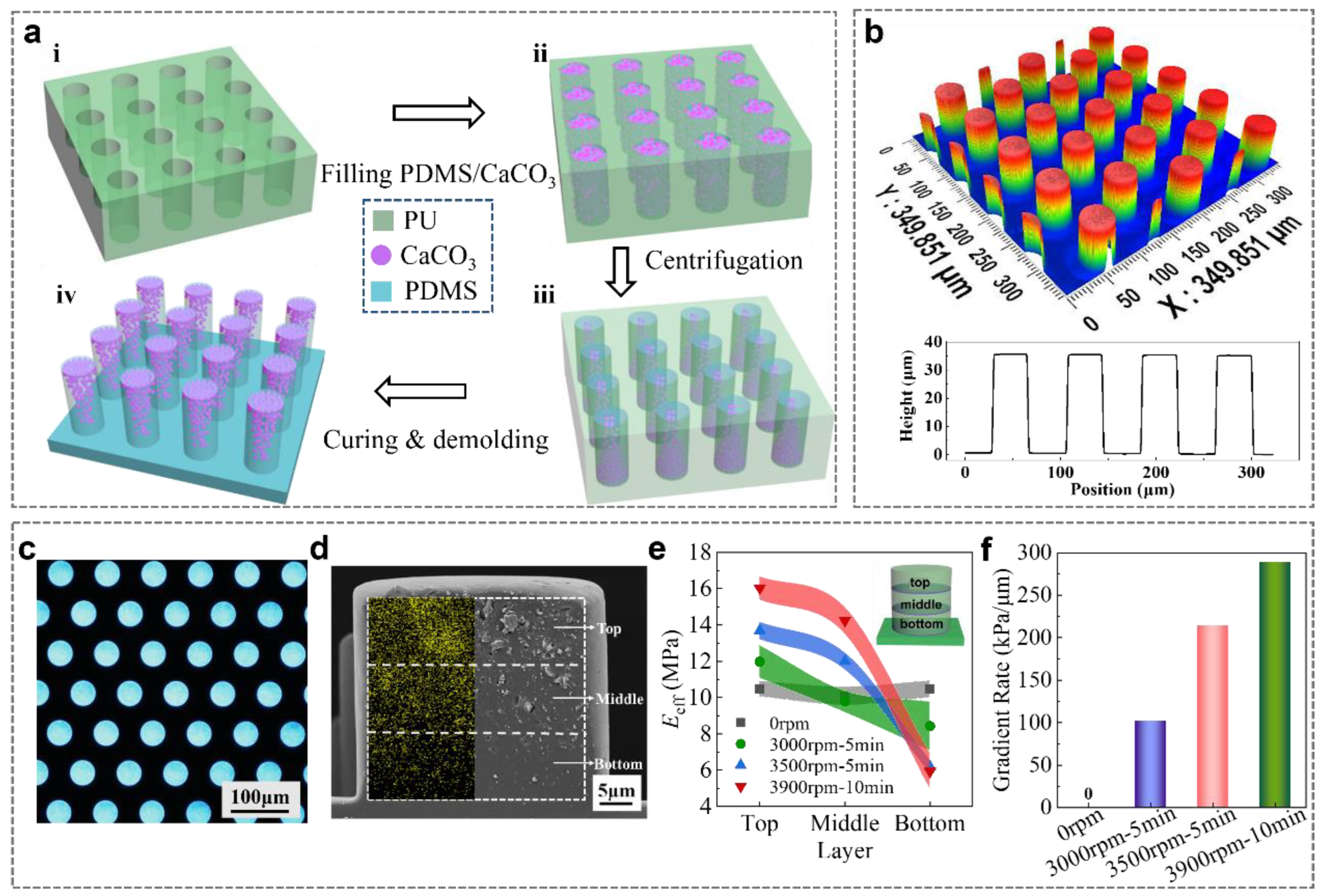
Figure 3.
Evaluation of adhesion performances. (a) Macroscope adhesion of PP, HP, and GP by hanging weight. (b) Dependence of Fad of GP70wt% on FL. (c) Dependence of Fad of GP70wt% on gradient rate compared with PP. (d) Macroscope Fad of micropillars with different AR. (e) Macroscope Fad capacity of 200 attachment/detachment cycles tests for GP. (f) Wet Fad of GP, HP, and PP. Shaded regions in (b,c) indicate the standard deviation.
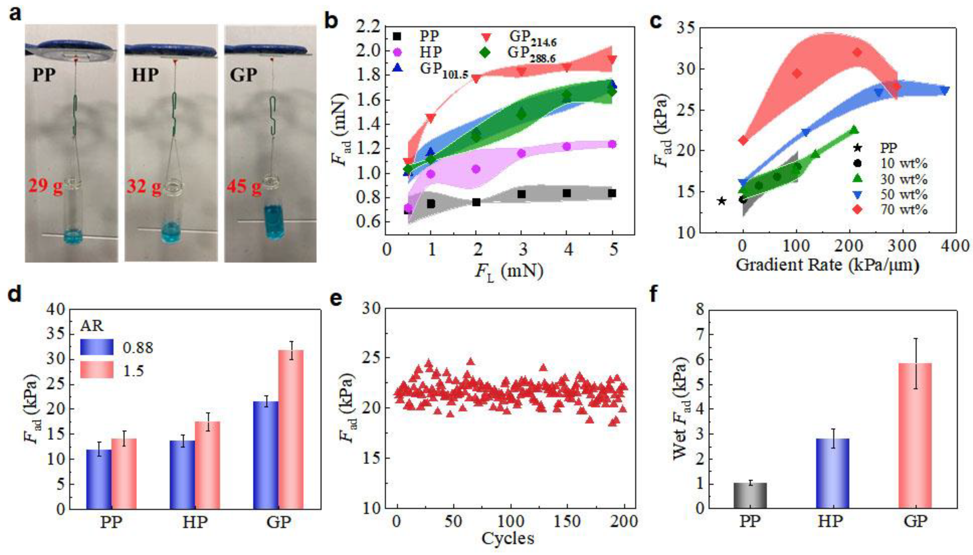
Figure 4.
(a) Schematic diagrams of the three states of a tilted surface and the micropillar: i. before contact, ii. during contact, and iii. full contact. (b) FL needed to form full contact with surfaces with tilting angles of 3°. (c) Simulated stress at the central separating interface of PP, HP, and GP.

Figure 5.
Application of GP adhesion. (a) Using a GP grasper to transfer a soft plasticine toy and (b) the 3D image, showing the surface of soft object intact as indicate by dashed box in (a). (c) Using a shape pliers grasper to transfer a soft plasticine toy and (d) the 3D image, showing the surface of soft object damaged as indicate by dashed box in (c). (e) The Sa of the soft plasticine toy after five transfers.

Figure 6.
Self-cleaning ability of GP. (a) Water contact angles of GP, HP, and PP. (b) Photos i to iii represent the initial state of GP, the GP with dust, and the GP after cleaning, respectively. (c) Fad of GP at states of i, ii, and iii as indicated in (b).
Figure 6.
Self-cleaning ability of GP. (a) Water contact angles of GP, HP, and PP. (b) Photos i to iii represent the initial state of GP, the GP with dust, and the GP after cleaning, respectively. (c) Fad of GP at states of i, ii, and iii as indicated in (b).
Publisher’s Note: MDPI stays neutral with regard to jurisdictional claims in published maps and institutional affiliations. |
© 2022 by the authors. Licensee MDPI, Basel, Switzerland. This article is an open access article distributed under the terms and conditions of the Creative Commons Attribution (CC BY) license (https://creativecommons.org/licenses/by/4.0/).
Share and Cite
MDPI and ACS Style
Liu, Q.; Meng, F.; Tan, D.; Shi, Z.; Zhu, B.; Xiao, K.; Xue, L. Gradient Micropillar Array Inspired by Tree Frog for Robust Adhesion on Dry and Wet Surfaces. Biomimetics 2022, 7, 209. https://doi.org/10.3390/biomimetics7040209
AMA Style
Liu Q, Meng F, Tan D, Shi Z, Zhu B, Xiao K, Xue L. Gradient Micropillar Array Inspired by Tree Frog for Robust Adhesion on Dry and Wet Surfaces. Biomimetics. 2022; 7(4):209. https://doi.org/10.3390/biomimetics7040209
Chicago/Turabian StyleLiu, Quan, Fandong Meng, Di Tan, Zhekun Shi, Bo Zhu, Kangjian Xiao, and Longjian Xue. 2022. "Gradient Micropillar Array Inspired by Tree Frog for Robust Adhesion on Dry and Wet Surfaces" Biomimetics 7, no. 4: 209. https://doi.org/10.3390/biomimetics7040209