

Biomimetic Design and Topology Optimization of Discontinuous Carbon Fiber-Reinforced Composite Lattice Structures


Abstract
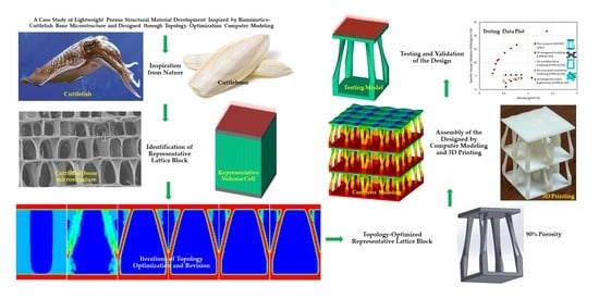
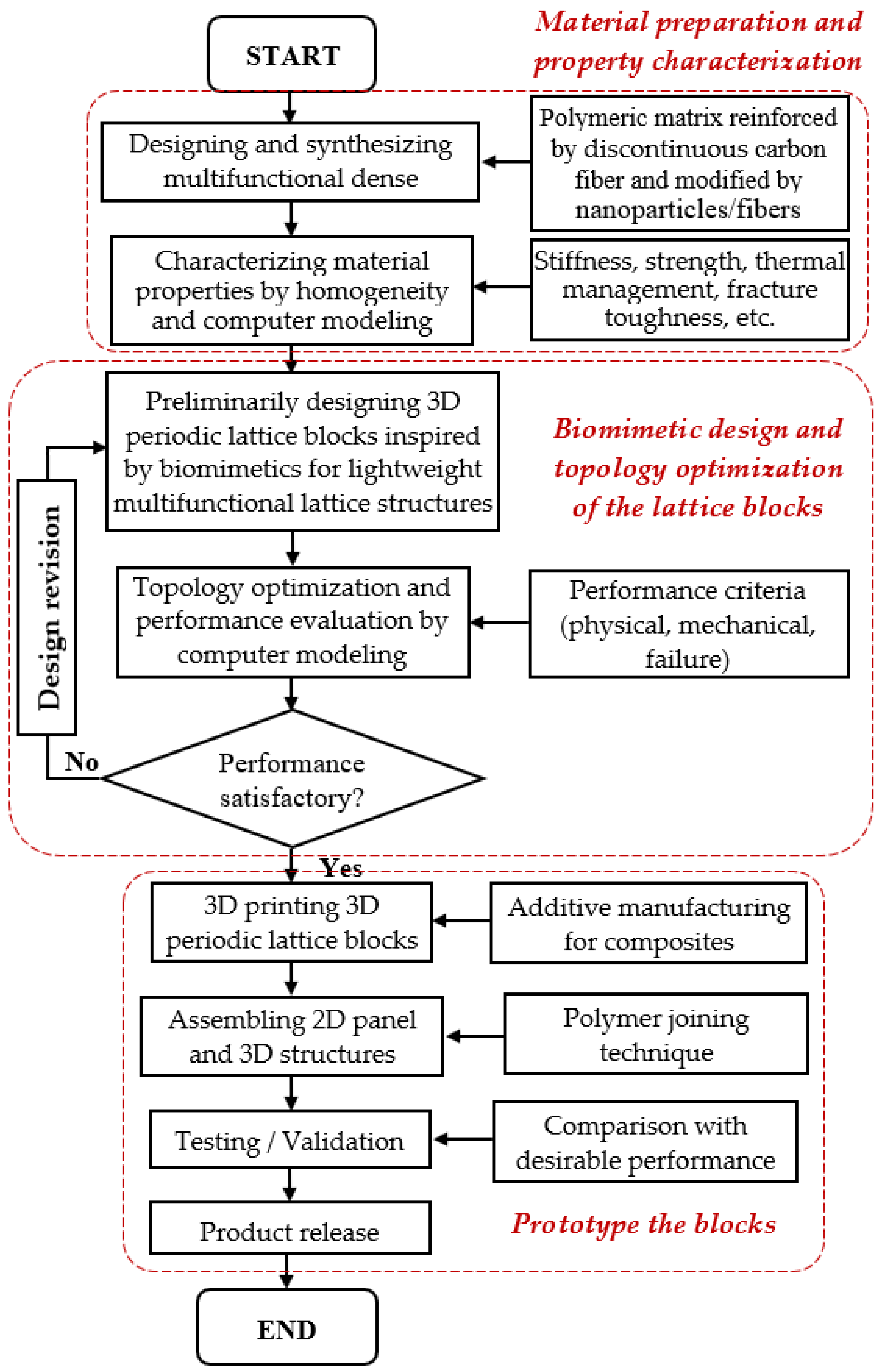
1. Introduction
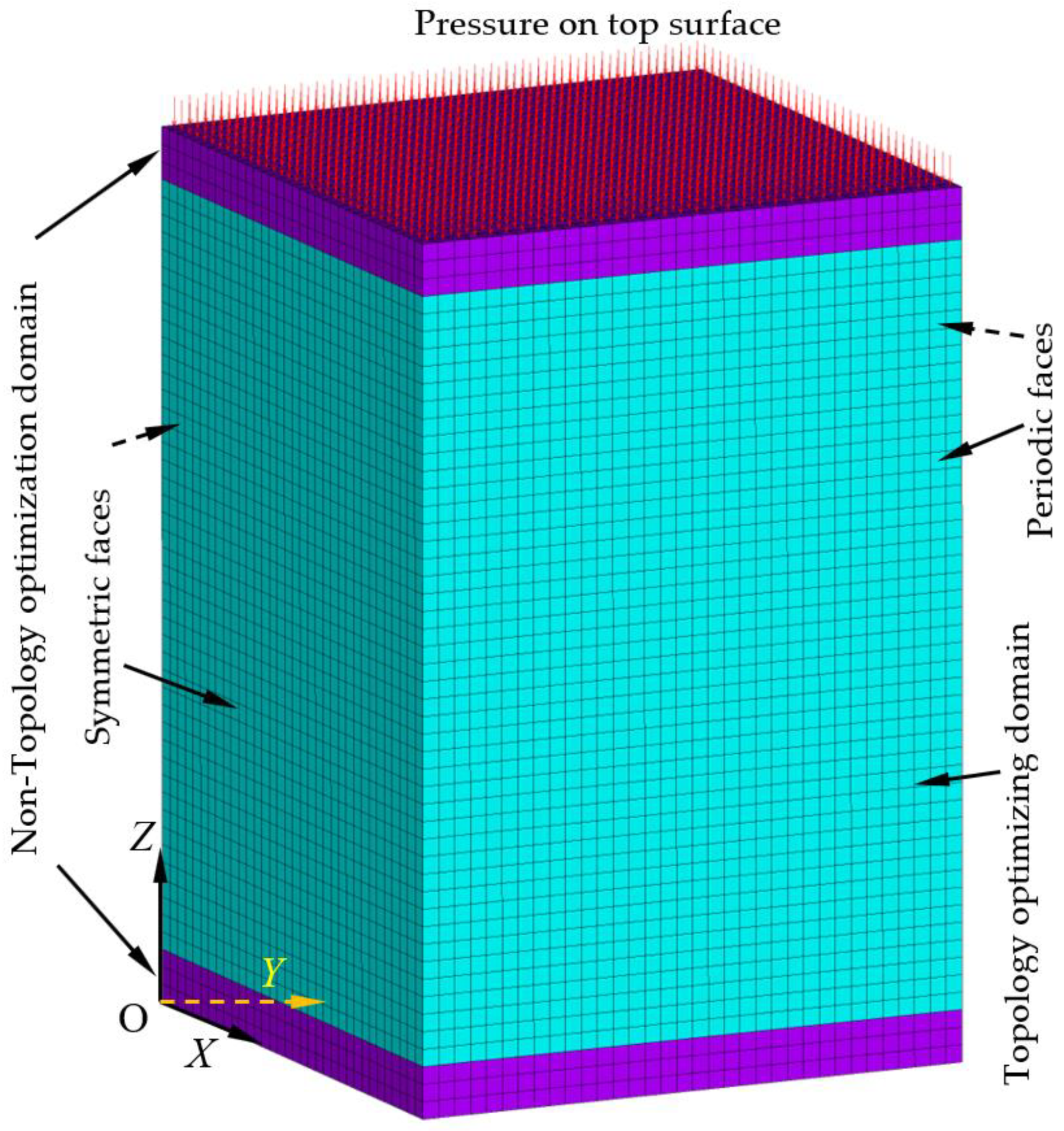
2. Topology Optimization of Lattice RVE of DiCFRPCs
3. Results and Discussion
3.1. Mesh Convergence Study of the Initial Periodic Lattice Block Model
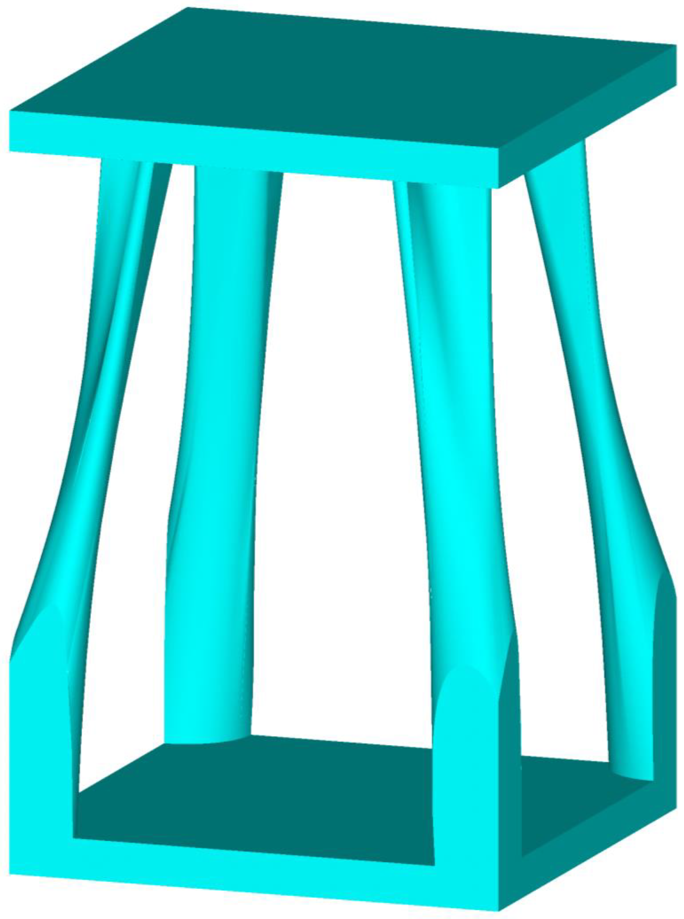
3.2. Topology Optimization
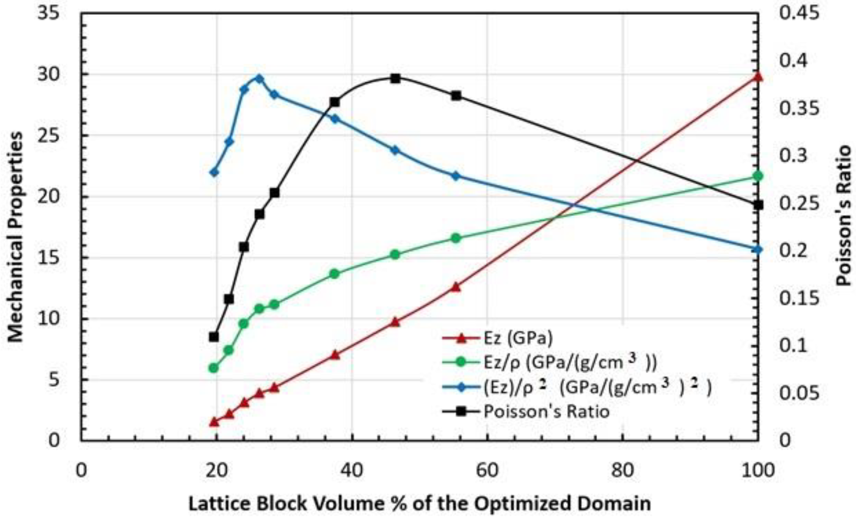
3.3. Mechanical Property Characterization of the Topology-Optimized Lattice Block
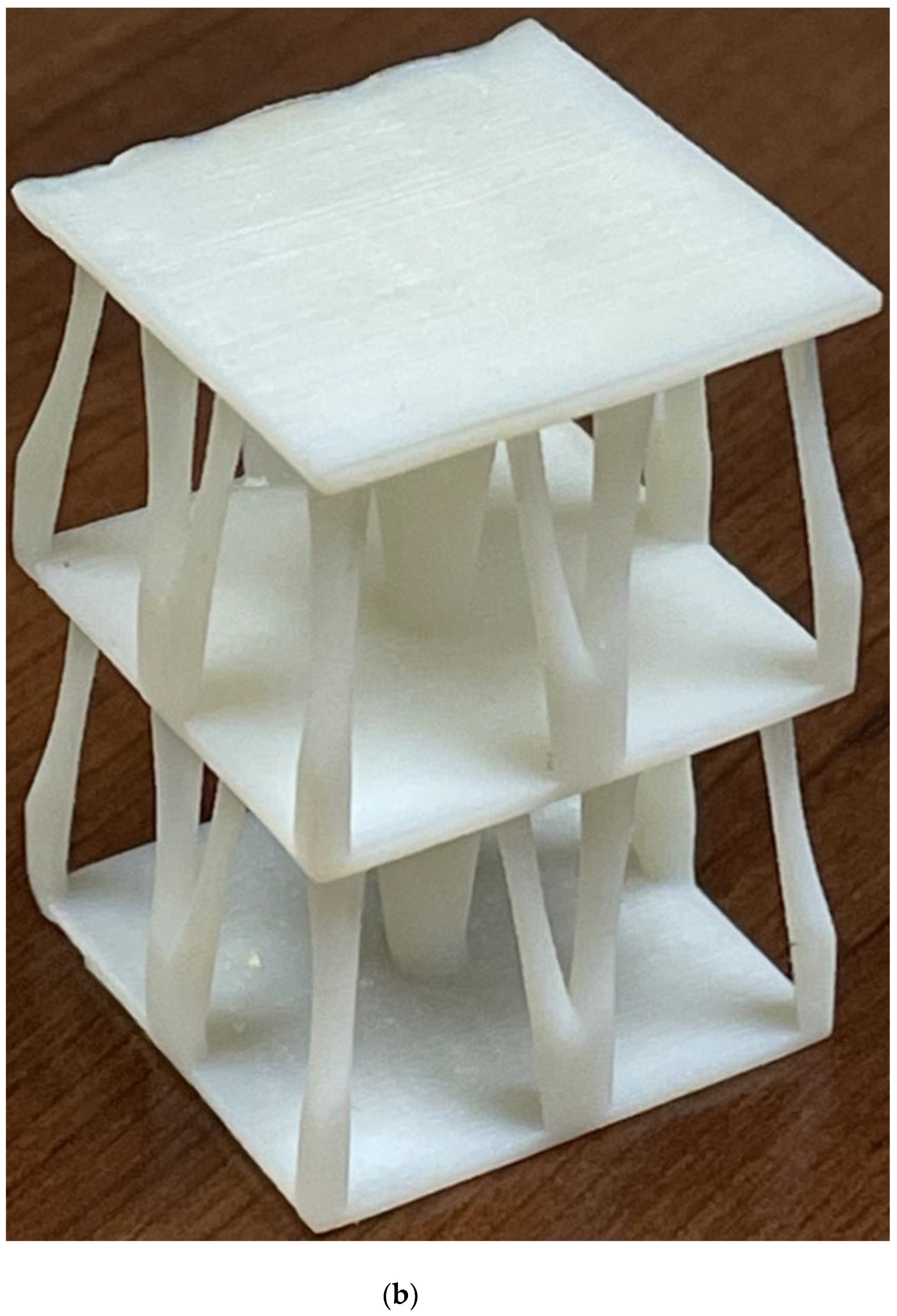
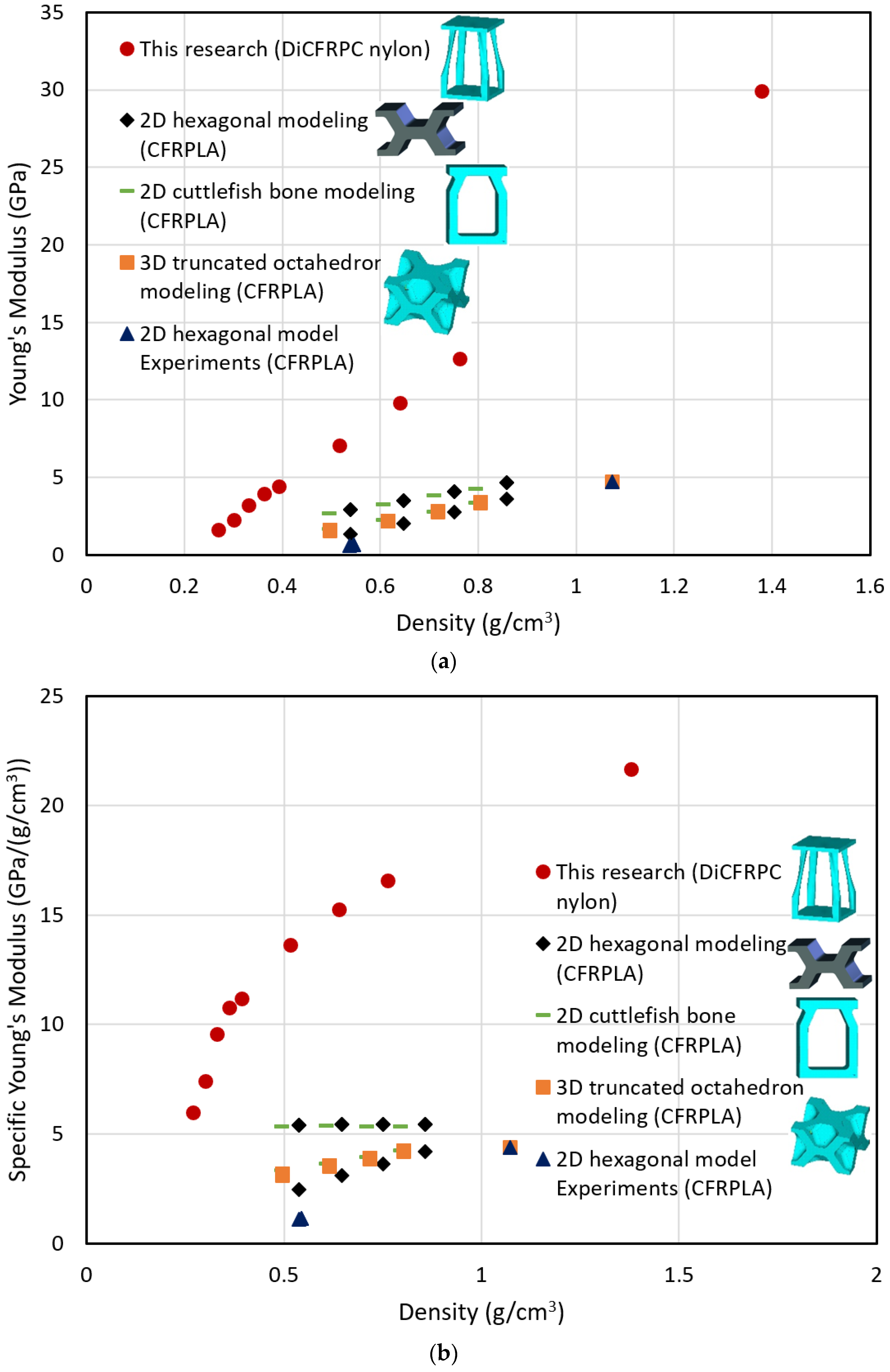
3.4. Validations
4. Conclusions
Funding
Data Availability Statement
Acknowledgments
Conflicts of Interest
References
- Wu, W.; Xia, R.; Qian, G.; Liu, Z.; Razavi, J.; Berto, F.; Gao, H. Mechanostructures: Rational mechanical design, fabrication, performance evaluation, and industrial application of advanced structures. Prog. Mater. Sci. 2023, 131, 101021. [Google Scholar] [CrossRef]
- Chung, D.D.L. A review of multifunctional polymer-matrix structural composites. Compos. Part B 2019, 160, 644–660. [Google Scholar] [CrossRef]
- González, C.; Vilatela, J.J.; Molina-Aldareguía, J.M.; Lopes, C.S.; LLorca, J. Structural composites for multifunctional applications: Current challenges and future trends. Prog. Mater. Sci. 2017, 89, 194–251. [Google Scholar] [CrossRef]
- Potes, F.C.; Silva, J.M.; Gamboa, P.V. Development and characterization of a natural lightweight composite solution for aircraft structural applications. Compos. Struct. 2016, 136, 430–440. [Google Scholar] [CrossRef]
- Gibson, R.F. A review of recent research on mechanics of multifunctional composite materials and structures. Compos. Struct. 2010, 92, 2793–2810. [Google Scholar] [CrossRef]
- Bhat, G. Structure and Properties of High-Performance Fibers; Elsevier: Amsterdam, The Netherlands, 2016. [Google Scholar]
- Xiong, J.; Ma, L.; Pan, S.D.; Wu, L.Z.; Papadopoulos, J.; Vaziri, A. Shear and bending performance of carbon fiber composite sandwich panels with pyramidal truss cores. Acta Mater. 2012, 60, 1455–1466. [Google Scholar] [CrossRef]
- Xiong, J.; Vaziri, A.; Ma, L.; Papadopoulos, J.; Wu, L.Z. Compression and impact testing of two-layer composite pyramidal-core sandwich panels. Compos. Struct. 2012, 94, 793–801. [Google Scholar] [CrossRef]
- Cheung, K.C.; Gershenfeld, N. Reversibly assembled cellular composite materials. Science 2013, 341, 1219–1221. [Google Scholar] [CrossRef] [PubMed]
- LLorca, J.; González, C.; Molina-Aldareguía, J.M.; Segurado, J.; Seltzer, R.; Sket, F.; Rodríguez, M.; Sádaba, S.; Muñoz, R.; Canal, L.P. Multiscale modeling of composite materials: A roadmap towards virtual testing. Adv. Mater. 2011, 23, 5130–5147. [Google Scholar] [CrossRef]
- LLorca, J.; González, C.; Molina-Aldareguía, J.M.; Lopes, C.S. Multiscale modeling of composites. JOM 2013, 65, 215–225. [Google Scholar] [CrossRef]
- Espinosa, H.D.; Juster, A.L.; Latourte, F.J.; Loh, O.Y.; Gregoire, D.; Zavattieri, P.D. Tablet-level origin of toughening in abalone shells and translation to synthetic composite materials. Nat. Commun. 2011, 2, 173. [Google Scholar] [CrossRef]
- Evans, A.G.; Hutchinson, J.W.; Fleck, N.A.; Ashby, M.F.; Wadley, H.N.G. The topological design of multifunctional cellular metals. Prog. Mater. Sci. 2001, 46, 309–327. [Google Scholar] [CrossRef]
- Gibson, L.; Ashby, M. Cellular Solids: Structure and Properties, 2nd ed.; Part of Cambridge Solid State Science Series; Clarke, D., Suresh, S., Ward, I., Eds.; Cambridge University Press: Cambridge, MA, USA, 1999. [Google Scholar]
- Xiong, J.; Mines, R.; Ghosh, R.; Vaziri, A.; Ma, L.; Ohrndorf, A.; Christ, H.-J.; Wu, L. Advanced micro-lattice Materials. Adv. Eng. Mater. 2015, 17, 1253–1264. [Google Scholar] [CrossRef]
- Wei, K.; Chen, X.; Mo, F.; Wen, W.; Fang, D. Design and analysis of integrated thermal protection system based on lightweight C-SiC pyramidal lattice core sandwich panel. Mater. Des. 2016, 111, 435–444. [Google Scholar] [CrossRef]
- Barthelat, F. Architectured materials in engineering and biology: Fabrication, structure, mechanics and performance. Int. Mater. Rev. 2015, 60, 413–430. [Google Scholar] [CrossRef]
- Sen, S.; Schofield, E.; O’Dell, J.S.; Deka, L.; Pillay, S. The development of a multifunctional composite material for use in human space exploration beyond low-earth orbit. JOM 2009, 61, 23–31. [Google Scholar] [CrossRef]
- Nakajima, H. Fabrication, properties and application of porous metals with directional pores. Prog. Mater. Sci. 2007, 52, 1091–1173. [Google Scholar] [CrossRef]
- Smith, B.H.; Szyniszewski, S.; Hajjar, J.F.; Schafer, B.W.; Arwade, S.R. Steel foam for structures: A review of applications, manufacturing and material properties. J. Constr. Steel Res. 2012, 71, 1–10. [Google Scholar] [CrossRef]
- Cadman, J. The Design of Cellular Materials Inspired by Nature-Characterisation, Fabrication and Application. Ph.D. Thesis, The University of Sydney, Sydney, Australia, 2012. [Google Scholar]
- Fan, H.-L.; Zeng, T.; Fang, D.-N.; Yang, W. Mechanics of advanced fiber reinforced lattice composites. Acta Mech. Sin. 2010, 26, 825–835. [Google Scholar] [CrossRef]
- Xu, B.; Yin, S.; Wang, Y.; Li, H.; Zhang, B.; Ritchie, R.O. Long-fiber reinforced thermoplastic composite lattice structures: Fabrication and compressive properties. Compos. Part A 2017, 97, 41–50. [Google Scholar] [CrossRef]
- Gao, Y.; Zhou, Z.; Hu, H.; Xiong, J. New concept of carbon fiber reinforced composite 3D auxetic lattice structures based on stretching-dominated cells. Mech. Mater. 2021, 152, 103661. [Google Scholar] [CrossRef]
- Zhao, Y.; Liu, M.; Zhang, T.; Xu, B.; Zhang, B. Compressive properties of reversibly assembled lattice structures. J. Reinf. Plast. Compos. 2021, 40, 422–436. [Google Scholar] [CrossRef]
- Poddar, P.; Olles, M.; Cormier, D. Mechanical response of carbon composite octet truss structures produced via axial lattice extrusion. Polymers 2022, 14, 3553. [Google Scholar] [CrossRef] [PubMed]
- Rogala, M.; Tuchowski, W.; Czarnecka-Komorowska, D.; Gawdzińska, K. Analysis and assessment of aluminum and aluminum-ceramic foam structure. Adv. Sci. Technol. Res. J. 2022, 16, 187–197. [Google Scholar] [CrossRef]
- Rogala, M.; Gajewski, J.; Gawdzińska, K. Crashworthness analysis of thin-walled aluminum columns filled with aluminum-silicon carbide composite foam. Compos. Struct. 2022, 299, 116102. [Google Scholar] [CrossRef]
- Benyus, J.M. Biomimicry: Innovation Inspired by Nature; Harper Perennial: New York, NY, USA, 2002. [Google Scholar]
- Yaraghi, N.A.; Kisailus, D. Biomimetic structural materials: Inspiration from design and assembly. Annu. Rev. Phys. Chem. 2018, 69, 23–57. [Google Scholar] [CrossRef]
- Sreeramagiri, S.V.S. Biomimetics: Applications in structural design. Int. J. Innov. Res. Sci. Eng. Technol. (IJIRSET) 2021, 10, 8899–8908. [Google Scholar]
- Mayer, G. New classes of tough composite materials—Lessons from natural rigid biological systems. Mater. Sci. Eng. C 2006, 26, 1261–1268. [Google Scholar] [CrossRef]
- Hu, Z.; Gadipudi, V.K. Topology optimization of lightweight lattice structural composites inspired by cuttlefish bone. Appl. Compos. Mater. 2019, 26, 15–27. [Google Scholar] [CrossRef]
- Song, J.; Wang, Y.; Zhou, W.; Ran, R.; Yu, B.; Lu, Y.; Li, L. Topology optimization-guided lattice composites and their mechanical characterizations. Compos. Part B 2019, 160, 402–411. [Google Scholar] [CrossRef]
- Bendsøe, M.P.; Sigmund, O. Topology Optimization, Theory, Methods and Applications; Springer: Berlin/Heidelberg, Germany; New York, NY, USA, 2003. [Google Scholar]
- Zhang, W.; Wang, F.; Dai, G.; Sun, S. Topology optimal design of material microstructures using strain energy-based method. Chin. J. Aeronaut. 2007, 20, 320–326. [Google Scholar] [CrossRef]
- Setoodeh, S.; Abdalla, M.M.; Gürdal, Z. Combined topology and fiber path design of composite layers using cellular automata. Struc. Multidisc. Optim. 2005, 30, 413–421. [Google Scholar] [CrossRef]
- Rodrigues, H.C. Topology optimization of structures: Applications in the simulation and design of cellular materials. In Computational Methods in Engineering and Science 2007; Springer: Berlin/Heidelberg, Germany, 2007; pp. 101–112. [Google Scholar]
- Otomori, M.; Andkjær, J.; Sigmund, O.; Yamada, T.; Izui, K.; Nishiwaki, S. Topology optimization for the microstructure design of plasmonic composites. In Proceedings of the 10th World Congress on Structural and Multidisciplinary Optimization, Orlando, FL, USA, 19–24 May 2013. [Google Scholar]
- Montemurro, M.; Bertolino, G.; Roiné, T. A general multi-scale topology optimization method for lightweight lattice structures obtained through additive manufacturing technology. Compos. Struct. 2021, 258, 113360. [Google Scholar] [CrossRef]
- Riot, A.; Panettieri, E.; Montemurro, M.; Guerard, S.; Girardot, J.; Cosculluela, A. Lattice structures under uniaxial loads: An experimental study. EPJ Web Conf. 2021, 250, 01006. [Google Scholar] [CrossRef]
- Strömberg, N. A new multi-scale topology optimization framework for optimal combinations of macro-layouts and local gradings of TPMS-based lattice structures. Mech. Based Des. Struct. Mach. 2022, 1–18. [Google Scholar] [CrossRef]
- Sherrard, K.M. Cuttlebone morphology limits habitat depth in eleven species of Sepia (Cephalopoda: Sepiidae). Biol. Bull. 2000, 198, 404–414. [Google Scholar] [CrossRef] [PubMed]
- Mayer, G. Rigid biological systems as models for synthetic composites. Science 2005, 310, 1144–1147. [Google Scholar] [CrossRef]
- Gower, D.; Vincent, J.F.V. The mechanical design of the cuttlebone and its bathymetric implications. Biomimetics 1996, 4, 37–57. [Google Scholar]
- Barthelat, F.; Espinosa, H.D. Elastic properties of nacre aragonite tablets. In Proceedings of the 2003 SEM Annual Conference and Exposition on Experimental and Applied Mechanics, Charlotte, NC, USA, 2–4 June 2003. [Google Scholar]
- Kolednik, O.; Predan, J.; Fischer, F.D.; Fratzl, P. Bioinspired design criteria for damage-resistant materials with periodically varying microstructure. Adv. Funct. Mater. 2011, 21, 3634–3641. [Google Scholar] [CrossRef]
- Zhou, S.; Li, Q. The relation of constant mean curvature surfaces to multiphase composites with extremal thermal conductivity. J. Phys. D Appl. Phys. 2007, 40, 6083–6093. [Google Scholar] [CrossRef]
- de Kruijf, N.; Zhou, S.; Li, Q.; Mai, Y.-W. Topological design of structures and composite materials with multiobjectives. Int. J. Solids Struct. 2007, 44, 7092–7109. [Google Scholar] [CrossRef]
- Herreto-Pérez, D.; Picó-Vicente, S.G.; Martínez-Barberá, H. Efficient distributed approach for density-based topology optimization using coarsening and h-refinement. Comput. Struct. 2022, 265, 106770. [Google Scholar] [CrossRef]
- Alvarez, H.A.; Zambrano, H.R.; Silva, O.M. Influence of density-based topology optimization parameters on the design of periodic cellular materials. Materials 2019, 12, 3736. [Google Scholar] [CrossRef]
- Allaire, G.; Dapogny, C.; Jouve, F. Shape and topology optimization. In Handbook of Numerical Analysis; Bonito, A., Nochetto, R.H., Eds.; Geometric partial differential equations, part II; Elsevier: Amsterdam, The Netherlands, 2021; Volume 22. [Google Scholar] [CrossRef]
- Li, X.; Zhao, L.; Liu, Z. Topology optimization of continuum structure based on ANSYS. MATEC Web Conf. 2017, 95, 07020. [Google Scholar] [CrossRef]
- Barbero, E.J. Finite Element Analysis of Composite Materials; CRC Press: Boca Raton, FL, USA, 2008. [Google Scholar]
- Hu, Z.; Arefin, M.R.H.; Yan, X.; Fan, Q.H. Mechanical property characterization of carbon nanotube modified polymeric nanocomposites by computer modeling. Compos. Part B 2014, 56, 100–108. [Google Scholar] [CrossRef]
- Hu, Z.; Karki, R. Prediction of mechanical properties of three-dimensional fabric composites reinforced by transversely isotropic carbon fibers. J. Compos. Mater. 2015, 49, 1513–1524. [Google Scholar] [CrossRef]
- Hu, Z.; Hossan, M.R. Strength evaluation and failure prediction of short carbon fiber reinforced nylon spur gears by finite element modeling. Appl. Compos. Mater. 2013, 20, 315–330. [Google Scholar] [CrossRef]
- ANSYS Inc. Theory Reference—ANSYS 2023R1; ANSYS Inc.: Canonsburg, PA, USA, 2023. [Google Scholar]
- Hu, Z.; Thiyagarajan, K.; Bhusal, A.; Letcher, T.; Fan, Q.H. Design of ultra-lightweight and high-strength cellular structural composites inspired by biomimetics. Compos. Part B 2017, 121, 108–121. [Google Scholar] [CrossRef]
- Zhang, X.; Lee, H.; Weisgraber, T.H.; Shusteff, M.; Deotte, J.; Duoss, E.B.; Kuntz, J.D.; Biener, M.M.; Ge, Q.; Jackson, J.A.; et al. Ultra-light, ultra-stiff mechanical metamaterials. Science 2014, 344, 1373–1377. [Google Scholar] [CrossRef]


| Young’s Modulus (GPa) | Shear Modulus (GPa) | Poisson’s Ratio | Density ρ (kg/m3) | |||
|---|---|---|---|---|---|---|
| Ex | 5.57 | Gxy | 2.16 | νxy | 0.29 | 1380 |
| Ey | 5.57 | Gyz | 7.41 | νyz | 0.047 | |
| Ez | 29.9 | Gzx | 7.41 | νzx | 0.25 | |
| Mesh Size (μm) | Total Elements | Total Nodes | Maximum Displacement (μm) |
|---|---|---|---|
| 50 | 12 | 111 | 0.0309 |
| 40 | 36 | 264 | 0.0309 |
| 35 | 45 | 320 | 0.0309 |
| 30 | 80 | 515 | 0.0309 |
| 25 | 96 | 605 | 0.0309 |
| 20 | 200 | 1152 | 0.0309 |
| 17.5 | 324 | 1771 | 0.0309 |
| 15 | 490 | 2576 | 0.0309 |
| 12.5 | 768 | 3897 | 0.0309 |
| 10 | 1500 | 7271 | 0.0309 |
| 8 | 3211 | 14,924 | 0.0309 |
| 6 | 7225 | 32,436 | 0.0309 |
| 5 | 12,000 | 52,940 | 0.0309 |
| 4 | 23,750 | 102,752 | 0.0309 |
| 3 | 57,800 | 245,105 | 0.0309 |
| Mesh Size (μm) | Total Elements | Total Nodes | Maximum Displacement (μm) | Young’s Modulus (GPa) |
|---|---|---|---|---|
| 10 | 85,097 | 129,527 | 9.1033 | 1.0471 |
| 5 | 124,364 | 185,968 | 9.1781 | 1.0716 |
| 4 | 137,916 | 206,287 | 9.1815 | 1.0732 |
| 3 | 183,201 | 273,919 | 9.1904 | 1.0732 |
| Material | Density ρ (g/cm3) | Volume % | E (GPa) | E/ρ (106 m2 S−2) | νE/ρ (106 m2 S−2) |
|---|---|---|---|---|---|
| PLA | 1.19 | 100 | 2.865 | 2.408 | 1.422 |
| CFRPLA * | 1.073 | 100 | 4.711 | 4.390 | 2.023 |
| 2D Hexagon PLA in X-lateral ** | 0.609 | 51.2 | 0.505 | 0.829 | 1.167 |
| 2D Hexagon PLA in Y-lateral ** | 0.626 | 52.6 | 0.455 | 0.727 | 1.078 |
| 2D Hexagon ** CFRPLA in X-lateral | 0.545 | 50.8 | 0.622 | 1.141 | 1.447 |
| 2D Hexagon ** CFRPLA in lateral | 0.537 | 50.0 | 0.588 | 1.096 | 1.428 |
| 2D Hexagon ** CFRPLA in Y-lateral | 0.545 | 50.8 | 0.622 | 1.141 | 1.447 |
| 2D Cuttlebone PLA ** in X-lateral | 0.610 | 51.3 | 0.829 | 1.358 | 1.493 |
| 2D Cuttlebone PLA ** in Y-lateral | 0.610 | 51.3 | 1.470 | 2.408 | 1.988 |
| 2D Cuttlebone ** CFRPLA in X-lateral | 0.610 | 51.3 | 1.926 | 3.155 | 2.275 |
| 2D Cuttlebone ** CFRPLA in Y-lateral | 0.610 | 51.3 | 2.939 | 4.814 | 2.810 |
| 3D Octahedron ** PLA in X-axis | 0.617 | 51.9 | 0.923 | 1.496 | 1.557 |
| 3D Octahedron ** PLA in Y-axis | 0.617 | 51.9 | 0.853 | 1.383 | 1.497 |
| 3D Octahedron ** PLA in Z-axis | 0.617 | 51.9 | 0.943 | 1.529 | 1.574 |
| 3D Octahedron ** CFRPLA in X-axis | 0.556 | 51.9 | 1.853 | 3.331 | 2.448 |
| 3D Octahedron ** CFRPLA in Y-axis | 0.556 | 51.9 | 1.682 | 3.023 | 2.333 |
| 3D Octahedron ** CFRPLA in Z-axis | 0.556 | 51.9 | 1.880 | 3.379 | 2.466 |
| Aluminum | ~2.710 | 100 | ~69.0 | ~26.0 | 3.077 |
| Steel | ~7.85 | 100 | ~200 | ~25.0 | 1.790 |
| Titanium alloys | ~4.50 | 100 | ~112.5 | ~25.0 | 25.00 |
| Diamond (C) | ~3.53 | 100 | ~1220 | ~346 | 9.895 |
| This research (Nylon 66 with 30 vol.% CFs) in Z-axis | 1.380 | 100 | 29.87 | 21.64 | 3.960 |
| This research (Nylon 66 with 30 vol.% CFs) in Z-axis | 0.7636 | 55.3 | 12.65 | 16.57 | 4.658 |
Disclaimer/Publisher’s Note: The statements, opinions and data contained in all publications are solely those of the individual author(s) and contributor(s) and not of MDPI and/or the editor(s). MDPI and/or the editor(s) disclaim responsibility for any injury to people or property resulting from any ideas, methods, instructions or products referred to in the content. |
© 2023 by the author. Licensee MDPI, Basel, Switzerland. This article is an open access article distributed under the terms and conditions of the Creative Commons Attribution (CC BY) license (https://creativecommons.org/licenses/by/4.0/).
Share and Cite
Hu, Z. Biomimetic Design and Topology Optimization of Discontinuous Carbon Fiber-Reinforced Composite Lattice Structures. Biomimetics 2023, 8, 148. https://doi.org/10.3390/biomimetics8020148
Hu Z. Biomimetic Design and Topology Optimization of Discontinuous Carbon Fiber-Reinforced Composite Lattice Structures. Biomimetics. 2023; 8(2):148. https://doi.org/10.3390/biomimetics8020148
Chicago/Turabian StyleHu, Zhong. 2023. "Biomimetic Design and Topology Optimization of Discontinuous Carbon Fiber-Reinforced Composite Lattice Structures" Biomimetics 8, no. 2: 148. https://doi.org/10.3390/biomimetics8020148
APA StyleHu, Z. (2023). Biomimetic Design and Topology Optimization of Discontinuous Carbon Fiber-Reinforced Composite Lattice Structures. Biomimetics, 8(2), 148. https://doi.org/10.3390/biomimetics8020148