1. Introduction
The silicon photomultiplier (SiPM) is a new generation of highly sensitive semiconductor photodetector; consisting of multiple pixels of avalanche photodiodes operating in Geiger-mode, each pixel has dimensions ranging from several to several tens of microns, and is connected in parallel to a common load by a series resistor with a resistance ranging from 200 kΩ to 1 MΩ [
1]. It is gradually replacing traditional PMT in low-level light detection and sensing applications, because of its excellent advantages such as high gain, high photon detection efficiency (PDE), high time resolution, excellent photon-number resolving capability, insensitivity to magnetic field, low operating voltage, its robustness and its low cost [
2,
3]. The recovery time, or the photon-counting rate of SiPM is determined by the finite time taken to quench the avalanche, then reset the diode voltage to its initial bias value. This is essential for high flux photon detection in such applications as photon counting computer tomography (CT) [
4,
5,
6], which involves a high photon-counting rate and has potential to reduce the exposure time and radiation dose. If the photon-counting rate of SiPM could be increased to hundreds of MHz or GHz, it could be applied in photon reflectometry, quantum random number generators [
7,
8,
9], etc. The HPK MPPC S12570-010C/P, with active area of 3 × 3 mm
2, utilizes a small pixel size of 10 μm to achieve a high-speed recovery time. Its recovery time is shortened to 15 ns, but the peak PDE is reduced to 12% [
10], which limits its application. SensL designed a special fast output to increase the counting rate of SiPM [
11,
12]; the timing performance of SiPM was improved effectively. In addition, some certain mathematical processing are carried out for the signal can increase the counting rate of SiPM, such as derivative [
7,
13], and due to the pulse height and pulse area being lower than single photon response during the recovery time period, the gain of signal will be influenced. Recovery time is an important issue to be studied for SiPM.
The finite time taken to quench the avalanche and then reset the diode voltage to its initial bias value is defined as recovery time (or dead time) [
14]. The basic operation of SiPM was explained in ref. [
10,
15], the time constant for the junction capacitor recharging through the quenching resistors (
Rq) can be expressed as
trecharge~Cd·Rq, which is much longer than the discharging time (
tdischarge~Cd·Rd) for the junction, where
Cd represents the junction capacitor and
Rd represents the junction resistor. Thus, the recovery time (
t) approximately equals the recharging time (i.e.,
t~Cd·Rq), which means the recovery time of SiPM increases with junction capacitance and the resistance of the quenching resistor. Due to the limitations of the geometric fill factor, the SiPM with polysilicon quenching resistors has a larger microcell area and capacitance, and the polysilicon resistor is sensitive to the doping concentration which makes it difficult to lower its resistance, which results in a longer recovery time and limits the scope of its use.
SiPM with epitaxial quenching resistors (EQR SiPM) is one of the main SiPM technologies now under development [
16,
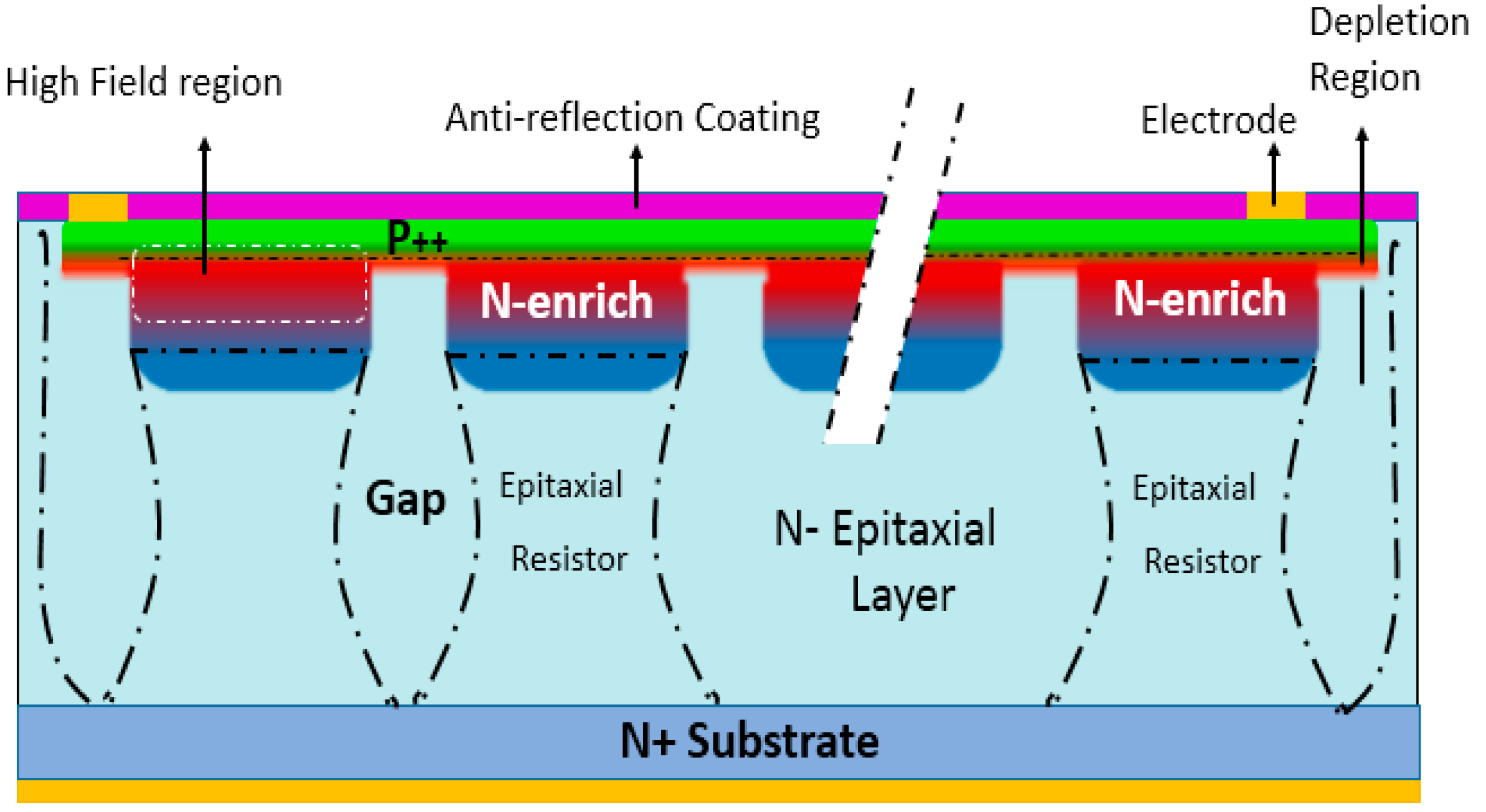
17]. As shown in
Figure 1, each APD cell (pixel) forms a high electric field, composing an enriched region between N-type epitaxial silicon substrate and
P++ cap layer, and it employs the un-depleted region in the epitaxial silicon layer below
P/N junction as the quenching resistor. Compared to conventional SiPM configurations that employ poly-silicon quenching resistors on the device surface, it is easier to achieve high density and small micro APD cells, thus obtaining a small junction capacitor; it is also easy to realize low resistance for the quenching resistors, simply based on the resistivity of the epitaxial layer and the geometrical scale. As a result, a low RC time constant of the pixel, or a short recovery time and fast counting rate for the EQR SiPM, can be expected. In addition, thanks to the high geometrical fill factor of the EQR SiPM with a high density of micro APD cells, both wide dynamic range and adequate PDE can be realized at the same time, which satisfactorily resolves the conflict between dynamic range and PDE existing in most commercial SiPMs with poly-silicon quenching resistors.
2. Materials and Method
In this study, the EQR SiPMs using a P on N diode configuration with an active area of 3 × 3 mm2 and 1.4 × 1.4 mm2 was provided by NDL (Novel Device Laboratory, Beijing, China). They demonstrated peak PDE over 30% at 420 nm, gain of 2 × 10⁵, crosstalk of 8%, dark count rate of 770 kHz/mm2 at room temperature and over voltage of 3.5 V. For the sake of a short recovery time, the pitch of the pixels is designed as 10 μm (i.e., the pixel density reaches to 10,000/mm2) and the resistance of the quenching resistor (Rq) is designed as ~200 kΩ.
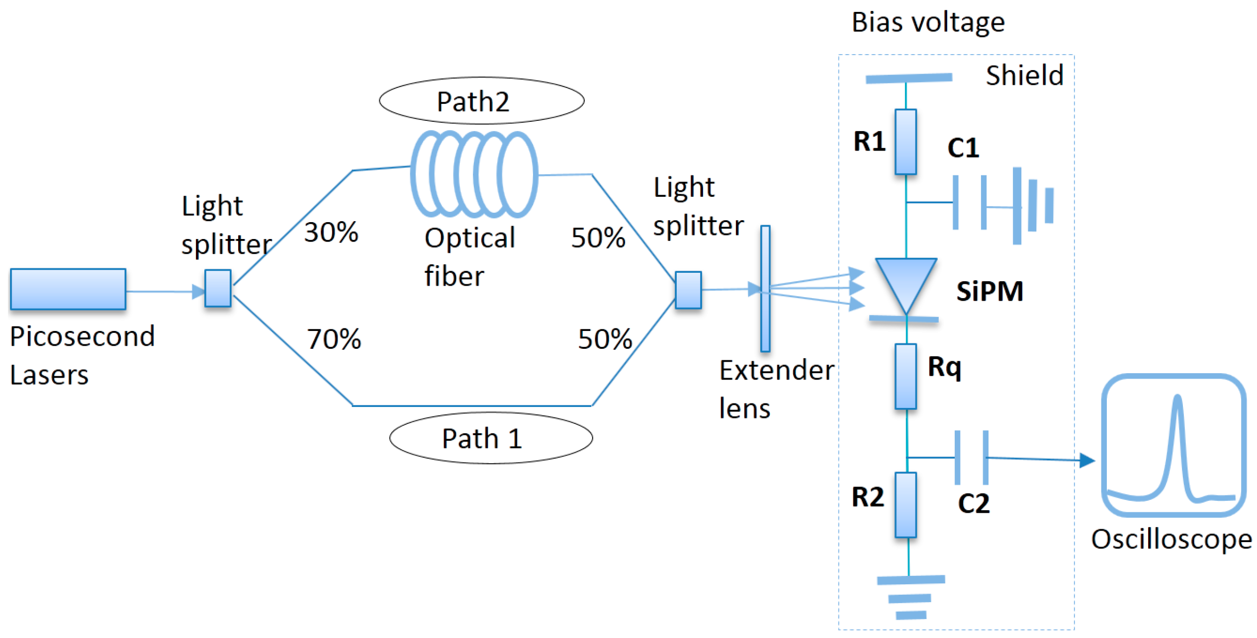
Two methods were demonstrated for study on the recovery time of SiPM: a double light pulse method and a waveform analysis method. The experimental setup mainly included the following elements: picosecond laser with wavelength of 532 nm and pulse width of 32 ps, light splitters, optical fibers, extender lens for uniform illumination, signal circuits, fast amplifiers (Femto HSA-Y-2-40), Lecroy oscilloscope waverunner 640 zi with bandwidth of 4 GHz and time resolution of 20 GS/s.
As shown in
Figure 2, the experimental setup for double light pulse method [
18] comprised two consecutive laser pulses with a relative time difference varying from several nanoseconds to hundreds nanoseconds; an oscilloscope was employed to record the charge number changing with the corresponding time, then the recovery time could be obtained by fitting out the recovery curve. For SiPM with different fired pixels, by illuminating whole sensor, the overall recovery time for all pixels was obtained; by illuminating the detector using a bare optical fiber with diameter of 120 μm to control the number of fired pixels in a restricted area, the partial recovery time was obtained. According to the relationship among the number of total pixels in SiPM (
Ntotal), fired pixels (
Nfired) and incident photons (
Nphoton) [
19]:
, the dynamic range of EQR SiPM has been characterized. The photon flux onto the device was controlled at the saturation level of the dynamic range (about 500 thousand photons) when measuring the overall recovery time. In addition, the stronger laser beam crossing path 1 and the weaker laser beam crossing path 2 must irradiate the same single pixel during the experiment. Firstly, the charge number was recorded when path 1 was active and path 2 was blocked; then path 2 was activated with zero time delay. If the number of charges detected by SiPM remained unchanged, this would indicate that the two beams are irradiating the same pixel.
After the breakdown of a pixel, its current is quenched by a voltage drop in the quenching resistor; some time is needed to fully recharge the pixel, and the magnitude of charge is reduced during this time [
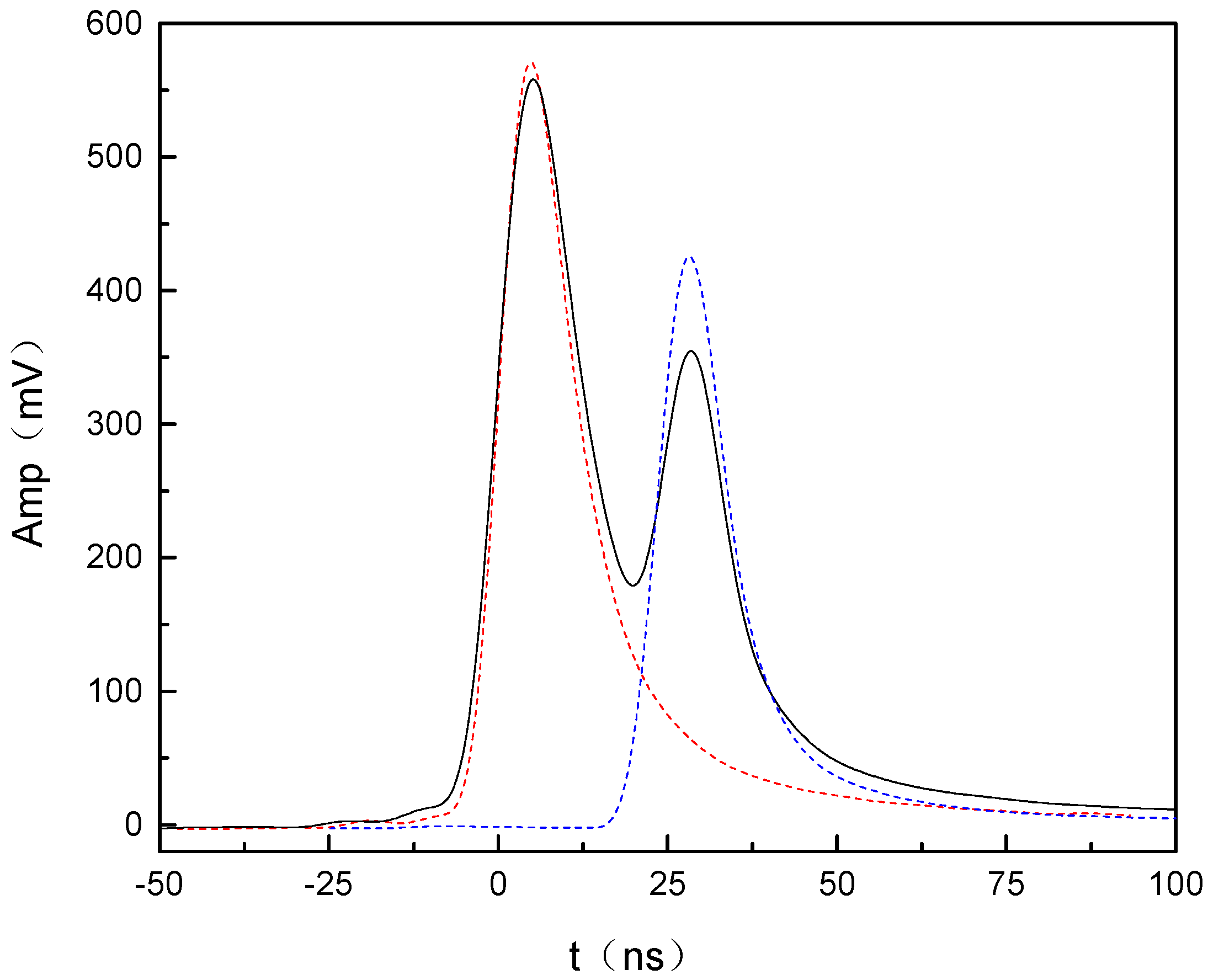
14]. The light response pulse waveform is shown in
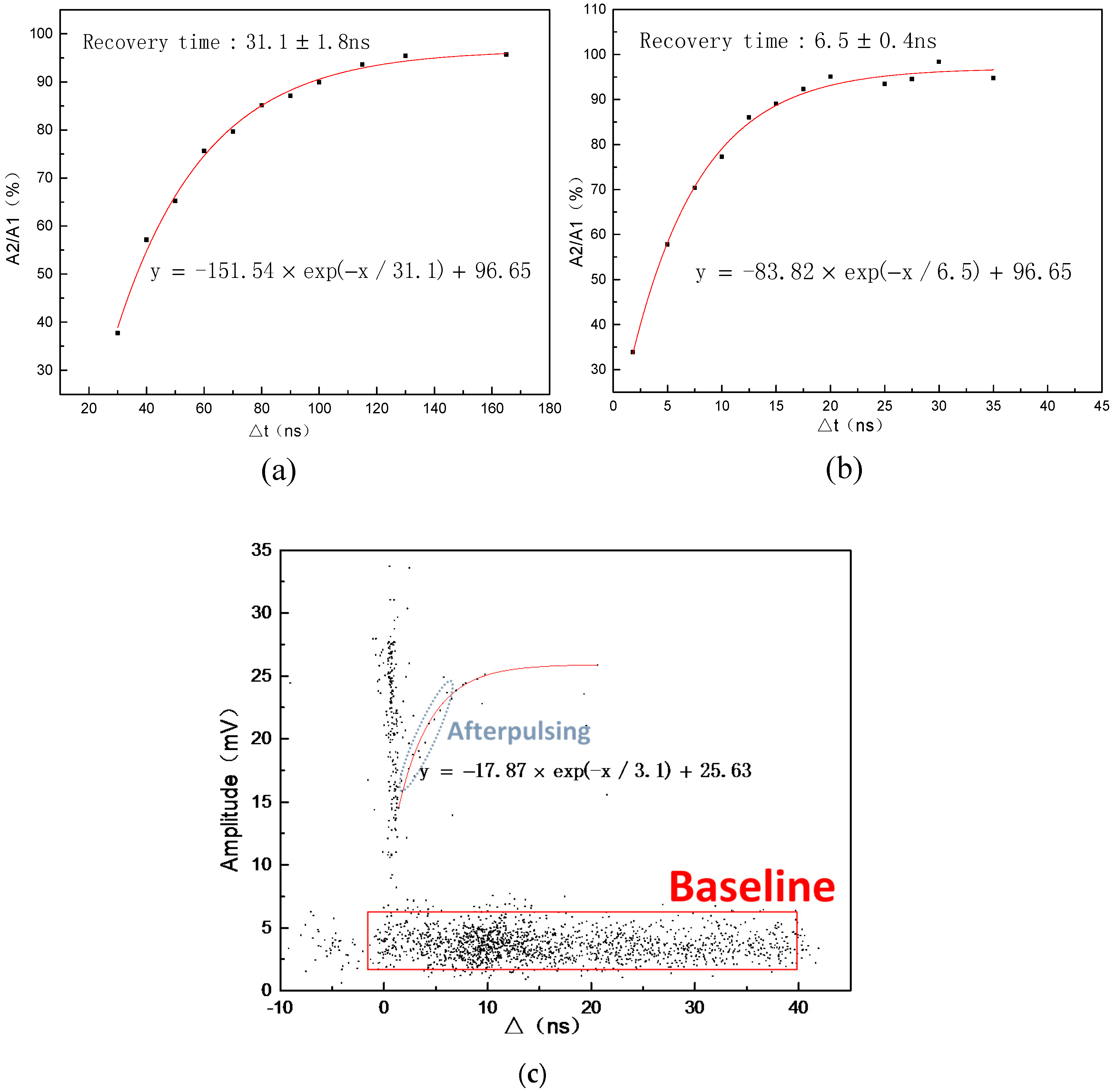
Figure 3, where the red dashed line shows the signal when path 2 is blocked; the blue dashed line shows the signal when path 1 is blocked, and the black line shows the signal when both path 1 and 2 are connected. The recovery time can be obtained by the following fitting function [
20]:
The decay time constant t1 is the fitting recovery time, A0 represents the charge number when the device was irradiated with path 2 only; A2 represents the charge number when path 1 and 2 irradiated the device simultaneously; x is the relative time difference between path 1 and path 2; A1 and y0 are amplitude and offset that do not affect the decay time constant.
The waveform analysis method aims to study the recovery time of a single pixel by extracting afterpulsing events and analyzing the signal waveform under dark conditions, its experimental setup is similar to
Figure 2. Carrier trapping and delayed release causes afterpulsing for a period of several nanoseconds to tens of nanoseconds after a breakdown [
1]. If an afterpulsing event occurs during the recovery time period, its pulse height and area will be lower than single photon response because the voltage drops in the quenching resistor. By tracing the interval time and the amplitude of afterpulsing using the internal function of the oscilloscope, thereby obtaining the time-amplitude distribution of the afterpulsing, the recovery curve for a single pixel of SiPM can be characterized.
3. Results and Discussions
The experimental results for 3 × 3 mm
2 EQR SiPM are shown in
Figure 4. We utilized the double light pulse method, obtaining the overall recovery time shown in
Figure 4a and the partial recovery time shown in
Figure 4b. The overall recovery time for a total of 90,000 fired pixels was 31.1 ± 1.8 ns. The partial recovery time for approximately 2000 fired pixels was 6.5 ± 0.4 ns; the partial recovery time in different positions was similar. With the waveform analysis method, a recovery time for single fired pixel of 3.1 ± 0.2 ns was obtained, and is shown in
Figure 4c. It proves that the recovery time is shortened with a reduction in the number of fired pixels.
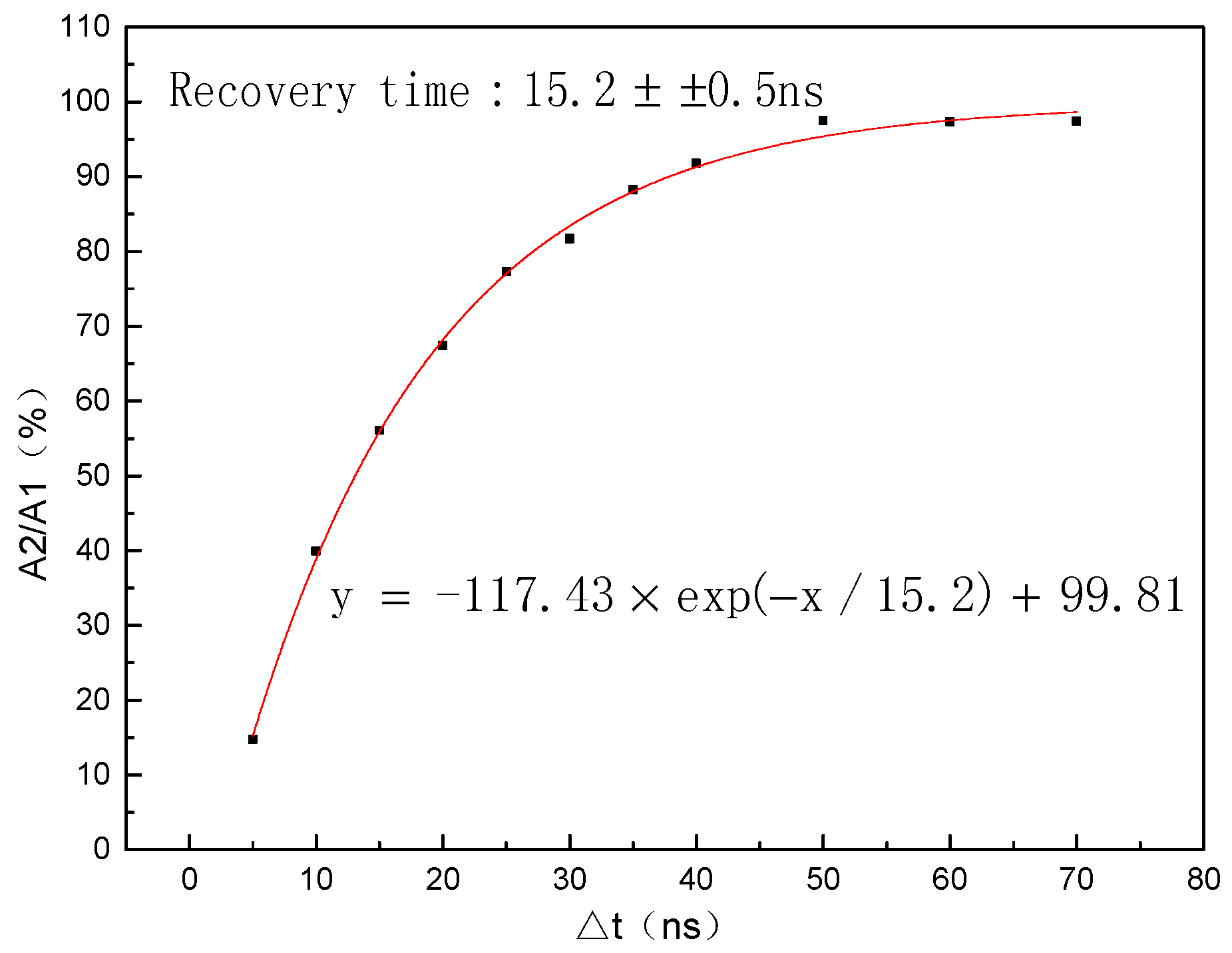
As shown in
Figure 5, the overall recovery time for 1.4 × 1.4 mm
2 EQR SiPM measured with the double light pulse method was 15.2 ± 0.5 ns when a total 20,000 pixels were fired. Compared with the 3 × 3 mm
2 device, its overall recovery time was significantly shortened. This reveals that the recovery time of EQR SiPM is strongly dependent on the active area of device.
For comparative analysis, a SensL SiPM C10020 with an active area of 1 × 1 mm
2 and a pixel size of 20 μm was also characterized; the overall recovery time was 22.3 ± 0.5 ns, which accords with the theoretical value of 23 ns, and the recharge time constant of C30020, −35, −50 with an active area of 3 × 3 mm
2, for pixel sizes of 20 μm, 35 μm and 50 μm, were 23 ns, 82 ns, 159 ns, respectively [
21]. The recovery time of SiPM with polysilicon resistor increases as the pixel size increases, and it is irrelevant to the device area for the similar pixel size, which is different from EQR SiPM.
An EQR SiPM with a small microcell size of 10 μm, a small junction capacitor and RC time constant can be achieved. Considering the linear relationship between the gain and the overvoltage: C~g·e/ΔV, the junction capacitance Cd of 15.5 fF was characterized, and the quenching resistors Rq of ~200 kΩ were obtained, which are in good agreement with the device design. According to the formula: , the recovery time of EQR SiPM was estimated at ~3.1 ns, which is very close to the experimental result from the waveform analysis method for a single pixel of SiPM.
The recovery time of the single photon response is close to the theoretical value, which is because it is a single photon signal waveform without waveform superposition. However, when the number of fired pixels increases gradually, the pixels at different position of device can’t possibly be fired synchronously, and the waveform superposition leads to pulse broadening and results in recovery time extending inevitably, and the greater the number of fired pixels, the more obvious the pulse broadening.
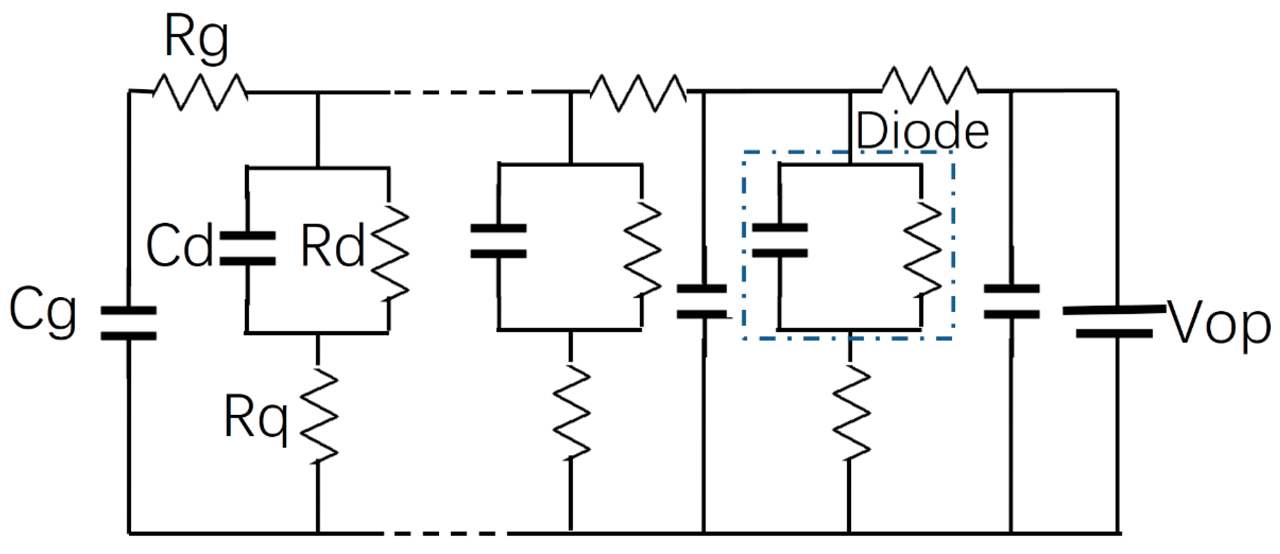
To better describe the signal transmission process in SiPM, the equivalent circuit diagram of EQR SiPM is given in
Figure 6, which is based on the equivalent circuit of SiPM in the literature [
22] and combining it with the peculiar structure of EQR SiPM showed in
Figure 1. The diode section consists of the
P/N junction (
P++ layer and
N-enrich region),
Rq is the quenching resistance, which consists of epitaxial resistor,
Rg is the resistance produced by the
P++ layer and
Cg is the capacitance produced by the
Gap region. The basic feature of RC transmission line model consisting of
Rg and
Cg, which are the major differences compared to the general equivalent circuit diagram. With regard to signal transmission [
23], the signal is not just a function of time (
t), it is also related to the position of the signal (
z). The signal transmission speed (
vg) can be expressed by the formula:
. The signal transmission speed of 3 × 3 mm
2 EQR SiPM is about 0.7 μm/ps. The required times for each APD cell in different regions to reach the electrode are not identical, which inevitably results in the pulse expanding and lengthening the recovery time. We found that the width of the signal waveform broadens obviously with the increasing of the number of fired pixels. The pulse width for the single photo-electron response is about 6 ns; it becomes about 9 ns when number of fired pixels is about 2000; and it is up to 25 ns when a total of about 90,000 cells are excited.
The values of capacitance and resistance at readout circuit in
Figure 2 affect the signal waveform. When a few e photons irradiate SiPM, which generates a small photocurrent that make the voltage drop across resistor
R1 can be ignored, a small capacitance
C2 can maintain the recharge and discharge process. However, increasing the number of incident photons to thousands and more, the voltage drop across resistor
R1 will be comparable to the signal voltage. In this case,
R1 needs to be reduced or removed for the signal integrity, and
C1 needs to be increased to ensure the charge and discharge operation with a high photocurrent. Under the strong illumination measurement for the double light pulse method,
C2 was up to several microfarad,
R2 was reduced and
R1 was removed. Reducing the operating voltage on SiPM would be helpful for shortening the recovery time, because the optical crosstalk and the afterpulsing will decrease, but the PDE will also decrease accordingly.
