New Ion Source Filament for Prolonged Ion Source Operation on A Medical Cyclotron

1
Accelerator Division, TRIUMF, Vancouver, BC V6T 2A3, Canada
2
Life Sciences Division, TRIUMF, Vancouver, BC V6T 2A3, Canada
*
Author to whom correspondence should be addressed.
Instruments 2019, 3(1), 5; https://doi.org/10.3390/instruments3010005
Submission received: 7 December 2018
/
Revised: 8 January 2019
/
Accepted: 14 January 2019
/
Published: 16 January 2019
(This article belongs to the Special Issue Instruments and Methods for Cyclotron Produced Radioisotopes)
Abstract
:Cyclotrons are an important tool for accelerator sciences including the production of medical isotopes for imaging and therapy. For their successful and cost-efficient operation, the planned and unplanned down time of the cyclotron needs to be kept at a minimum without compromising reliability. One of the often required maintenance activities is the replacement of the filament in the ion source. Here, we are reporting on a new ion source filament tested on a medical cyclotron and its prolonging effect on the ion source operation.
1. Introduction
Since their introduction in the 1930’s, cyclotrons play an important part in the production of radionuclides in a variety of applications, from basic physics, to agriculture and medicine [1]. At TRUMF, several cyclotrons and beam lines are dedicated to the production of medical isotopes for imaging and therapy [2]. The Life Sciences division employs the TR13 cyclotron [3,4], a 13 MeV negative-hydrogen machine, to produce most of their isotopes in gaseous, liquids and solid targets (e.g. 11C, 13N, 18F, 44Sc, 52Mn, 55Co, 61/64Cu, 68Ga, 86Y, 89Zr, 94mTc, 117/118/119Sb, 192Ir, 203Pb) [5].
One of the main components of a cyclotron is the ion source where the projectile beam is created. While this can be protons, negative hydrogen ions, or deuterons, negative hydrogen ions are favoured [6] as the beam can be extracted from the cyclotron via a stripping foil in the acceleration plane. The ions pass through a carbon stripper foil, changing their charge from −1 to +1 and therefore changing their trajectory in the magnetic field of the cyclotron [7] and leading to beam extraction onto a target. The TR13 cyclotron operates with an external multi-cusp negative ion source. This causes less activation and consequently lower personnel dose and radioactive waste during maintenance and decommissioning of the cyclotron than with an internal ion source [8]. General information about ion sources can be found in [9].
To create negative hydrogen ions, ultra-high purity hydrogen gas is flowing into the ion source chamber, where the ions are created, which are then accelerated into the plane of the cyclotron. To achieve this, a tantalum filament is heated via a high current to create electrons. A bias voltage is applied between the filament and the chamber wall to control the ionization. These electrons form a plasma, which is held in place by rare-earth magnets placed in several rings in the chamber (see Figure 1). A fast-feedback loop constantly monitors in real-time the value of the arc current between the filament and the chamber of the wall, and adjusts the filament current to maintain the arc current at a constant pre-set level. The H− ions are formed in the plasma. Several mechanisms are competing for the H− production and destruction (ν vibrational sate) [7]:
| H− Production: | ||
| H2* (ν ≥ 4) + e (~0.5 eV) → H− + H | Dissociative electron attachment, | σ = ~1.6 × 10⁻¹⁶ cm2 |
| H2 + e (~3.7 eV) → H− + H* | Dissociative electron attachment, | σ = ~1.6 × 10⁻²¹ cm2 |
| H2 (ν = 0) + e (~38 eV) H− + H+ + e | Polar dissociation, | σ = ~1.6 × 10⁻²⁰ cm2 |
| H− Destruction: | ||
| H− + H2 → H2 + H | Charge transfer, | σ = 2.5 × 10⁻¹³ cm2 |
| H− + e (≥15 eV) → H + 2e | Collisional detachment, | σ = 4 × 10⁻¹⁵ cm2 |
| H− + H2 → H2 + H | Collisional detachment, | σ = 1 × 10⁻¹⁵ cm2 |
To successfully produce H−, low and higher energy electrons from the ion source are therefore separated by the magnetic field arrangement, see [7].
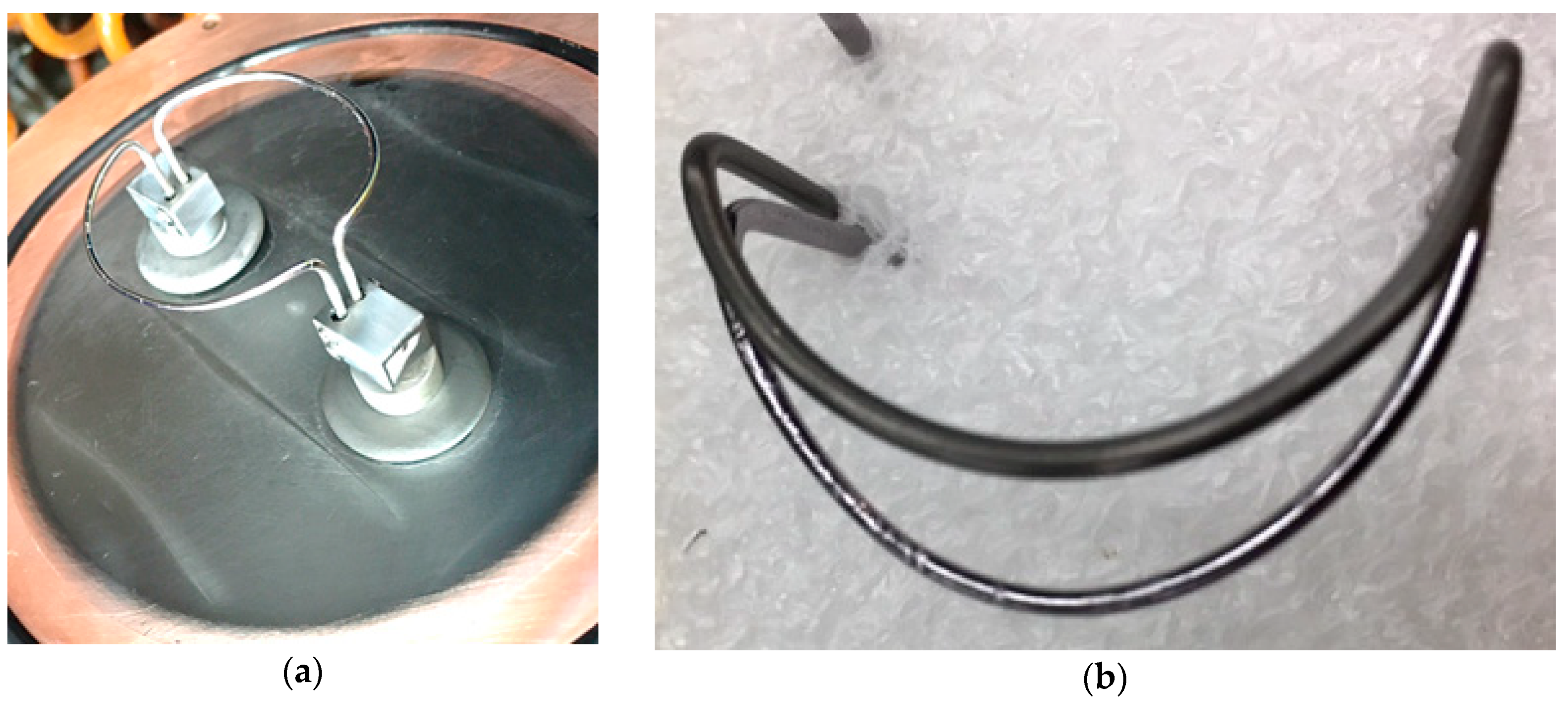
The filament design in the ion source of the TR13 cyclotron at TRIUMF has been in use for many years and is made of tantalum wire shaped like a half circle (Filament I), see Figure 2a. The filament is mounted in duplicate on the removable end plate of the ion source for easy access. Over time, the tantalum wire of the filament loses material and wears thin, see Figure 2b.
This is reflected in a dropping current flowing through Filament I during routine operation, see Figure 3. To avoid filament breakage and therefore loss of negative hydrogen beam, the Filament I pair is being replaced when the current drops to about 100 A at the TR13. At normal operation Filament I in the ion source needs to be replaced on average every three months to ensure beam delivery, which causes the cyclotron to be off for a minimum of a day each time as the ion source chamber needs to be vented, shielding needs to be removed, services need to be disconnected, the backplate of the ion source needs to be removed and the filament needs to be replaced. The reverse is then necessary before operation can resume. To significantly shorten this down time, a new spiral filament, Filament II, designed for the 520 MeV cyclotron at TRIUMF [5], was tested at the TR13 cyclotron.
2. Materials and Methods
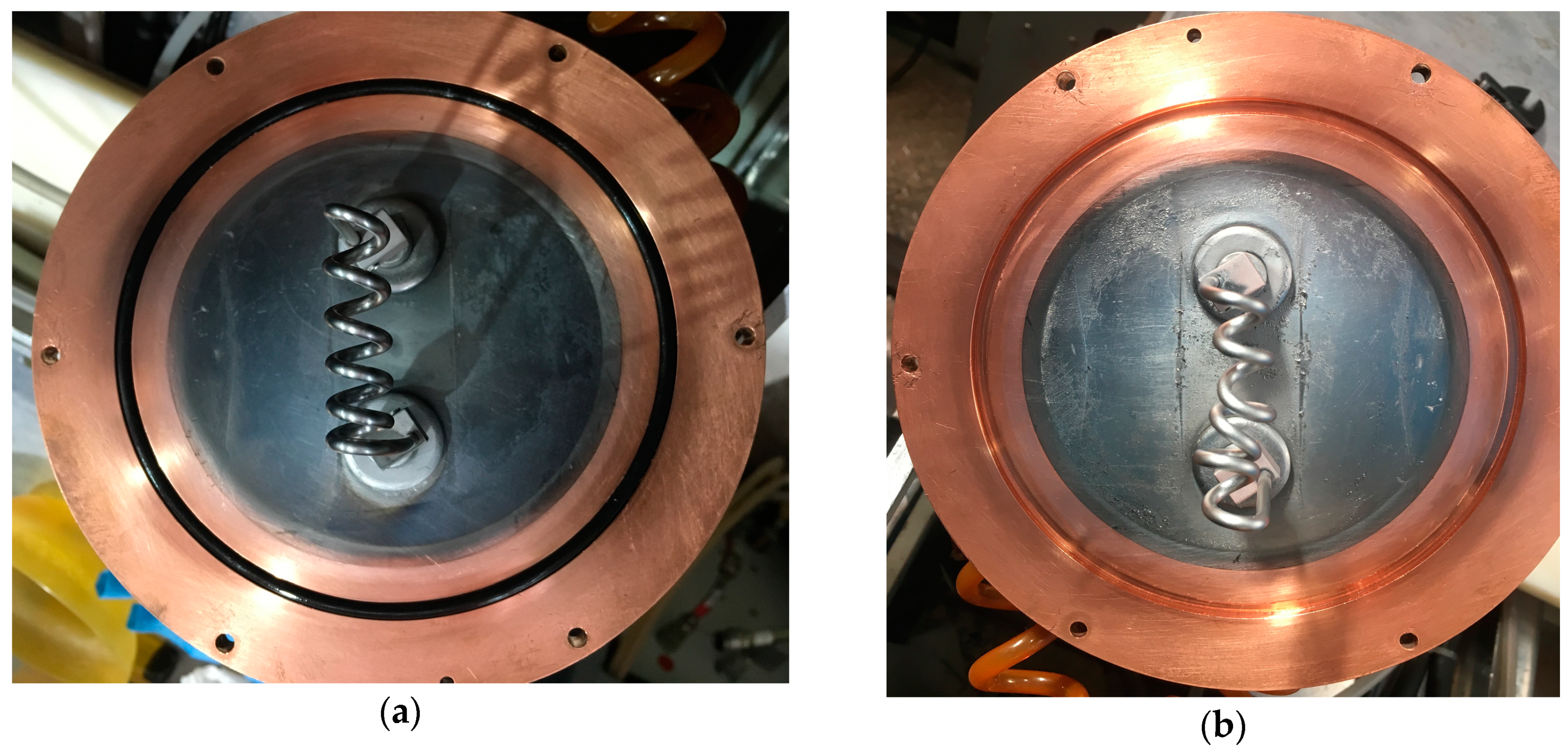
The TR13 cyclotron, the work horse of the Life Sciences Division at TRIUMF, is a 13 MeV cyclotron with an external ion source, accelerating negative-hydrogen ions. For more details of the design and operation see [3,4]. The ion source relies on a filament for the production of negative hydrogen ions which are then transported into the plane of the cyclotron for acceleration and bombardment of medical isotope targets. The new Filament II was originally designed for the external ion source at the 520 MeV cyclotron at TRUMF and has already been described in [7]. While a tantalum filament produces very bright H− beams, it is also known to degrade fast [7]. The new Filament II is made from a tungsten alloy, which degrades slower. The Filament II is shaped in house. Several lengths and shapes were studied as mentioned in [7] and the spiral filament in Figure 4a with an outer spiral diameter of 10 mm and six windings achieved the longest lifetime. As this new Filament II is slightly thicker (3.0 mm versus 1.5 mm for Filament I), a higher current is needed to give the same surface temperature and electron emission. To hold the new filament wire, the mounting stands on the ion-source back plate (see Figure 4) had to be modified to accept the 3.0 mm diameter. Due to the thicker wire, a higher filament current was necessary, 230 A at the beginning versus 150 A for Filament I. While our power supply (Xantrex, XKW, 12V and 250A) was able to provide this extra current, this should be taken into account when considering upgrading filaments. No other modification to the ion-source chamber, including the magnetic field, was necessary.
3. Results and Discussion
The operation of Filament II is the same as of the old Filament I. The automated routine tracking the currents and voltages was able to operate the new Filament II without any changes necessary. Figure 5. shows the filament current of the new Filament II over time. At the beginning of this graph, Filament I was still in use with its start-up current of ~150 µA and a fast current-drop. Shortly before month 8, the new Filament II was installed. While the higher start-up current of ~230 A is obvious, it is also very clear that the filament current declines significantly slower than for Filament I. We estimate from the observed drop that Filament I could be in use for about two years before it needs to be replaced.
Also shown in Figure 5 at around month 17, a sudden filament current drop down to 150 A was observed. This sudden drop was caused by the deformation of the spiral to the point that two neighboring windings touched and shorted, effectively shortening the filament length, see Figure 4b. While this reduced the current output of the ions source due to the shorter active length and made tuning for higher beam currents difficult and tedious, it should be noted that it did not hinder routine isotope production. In month 20, the Filament II was replaced and the filament current consequently recovered to the previously observed 230 A.
Due to the higher current necessary to operate Filament II, a temperature rise in the electrical cables feeding into the ion source was observed, see Figure 6. During operation, the cable supplying the new spiral filament rose to 47.0 °C. It should be noted that although our power supply is rated to provide the increased current as it is rated for up to 250 A, we plan on upgrading the supply in the future.
4. Conclusions
In this paper, we presented the operational experience of a new spiral filament [7] on our 13 MeV medical cyclotron. The switch from our old half-circle Filament I to the new spiral Filament II required only minimum mechanical modifications and no alteration in operation. The only significant change is the higher current necessary to ensure a similar electron emission as with the previous Filament I. While our power supply was able to accommodate this current rise, this could potentially lead to the need to purchase an upgraded power supply for other sites. With the new Filament II, it is now not necessary to change the ion source filament approximately every three months, and we estimate that during routine operation it should last over two years, greatly reducing our planned down time. A newer version of the Filament II tested at TRIUMF is resistant to sagging and deformation and will be tested at the TR13 in the near future. Pending final negotiations, the filament will be licensed to D-Pace [10].
Author Contributions
Conceptualization, K.J. and C.H.; Formal analysis, D.P. and K.J.; Funding acquisition, D.P.; Investigation, D.P., K.J., L.G. and S.V.; Methodology, D.P. and K.J.; Project administration, D.P.; Resources, D.P. and K.J.; Supervision, D.P.; Visualization, K.J. and C.H.; Writing—original draft, C.H.; Writing—review & editing, D.P.
Funding
TRIUMF receives federal funding via a contribution agreement with the National Research Council of Canada.
Conflicts of Interest
The authors declare no conflict of interest.
References
- Ruth, T.J. The production of radionuclides for radiotracers in nuclear medicine. Rev. Accel. Sci. Technol. 2009, 2, 17–33. [Google Scholar] [CrossRef]
- Hoehr, C.; Bénard, F.; Buckley, K.; Crawford, J.; Gottberg, A.; Hanemaayer, V.; Kunz, P.; Ladouceur, K.; Radchenko, V.; Ramogida, C.; et al. Medical isotope production at TRIUMF—From imaging to treatment. Phys. Procedia 2017, 90, 200–208. [Google Scholar] [CrossRef]
- Buckley, K.R.; Huser, J.; Jivan, S.; Chun, S.K.; Ruth, T.J. 11C-methane production in small volume, high pressure gas targets. Radiochim. Acta 2000, 88, 201–205. [Google Scholar] [CrossRef]
- Laxdal, R.E.; Altman, A.; Kuo, T. Beam measurements on a small commercial cyclotron. In Proceedings of the EPAC 94, London, UK, 27 June–1 July 1994; pp. 545–547. [Google Scholar]
- Infantino, A.; Oehlke, E.; Mostacci, D.; Schaffer, P.; Trinczek, M.; Hoehr, C. Assessment of the production of medial isotope using the Monte Carlo code FLUKA: Simulations against experimental measurements. Nucl. Instrum. Methods Phys. Res. B 2016, 366, 117–123. [Google Scholar] [CrossRef]
- Sluyters, T.; Prelec, K. Will negative hydrogen ion sources soon replace proton sources in high energy accelerators? In Proceedings of the IXth International Conference on High Energy Accelerators SLAC, Stanford, CA, USA, 2–7 May 1974; p. 536. [Google Scholar]
- Jayamanna, K.; Ames, F.; Bylinskii, I.; Lovera, M.; Minato, B. A 60 mA DC H− multi cusp ion source developed at TRIUMF. Nucl. Instrum. Methods Phys. Res. A 2018, 895, 150–157. [Google Scholar] [CrossRef]
- Korenev, S. Critical analysis of negative hydrogen ion sources for cyclotrons. In Proceedings of the 20th International Conference on Cyclotrons and their Applications, Vancouver, BC, Canada, 16–20 September 2013; p. 192. [Google Scholar]
- Ion Sources. Available online: https://inis.iaea.org/collection/NCLCollectionStore/_Public/26/001/26001458.pdf (accessed on 15 January 2019).
- D-Pace. Available online: http://www.d-pace.com/ (accessed on 15 January 2019).
Figure 1.
Sketch of the TR13 ion source.

Figure 2.
(a) Ion source back plate with two of the Filaments I mounted. The discoloration under the two filaments is a coating of worn-off filament material. (b) Used Filament I (bottom) and new Filament I (top). It can clearly be seen, that the filament wears thinner during operation.
Figure 2.
(a) Ion source back plate with two of the Filaments I mounted. The discoloration under the two filaments is a coating of worn-off filament material. (b) Used Filament I (bottom) and new Filament I (top). It can clearly be seen, that the filament wears thinner during operation.

Figure 3.
Filament current during operation of Filament I over time. The TR13 cyclotron is not operated 24 hours a day but is turned off after daily operation and for the weekend. The longer pause around month six is the annual shutdown during the Christmas holiday.
Figure 3.
Filament current during operation of Filament I over time. The TR13 cyclotron is not operated 24 hours a day but is turned off after daily operation and for the weekend. The longer pause around month six is the annual shutdown during the Christmas holiday.

Figure 4.
(a) Ion source back plate with new Filament II. (b) Ion source back plate with 6 months old Filament II. The operation deformed the spiral to the extent that neighboring windings touched and created an electrical short.
Figure 4.
(a) Ion source back plate with new Filament II. (b) Ion source back plate with 6 months old Filament II. The operation deformed the spiral to the extent that neighboring windings touched and created an electrical short.

Figure 5.
Filament current versus time. Until month eight, the old Filament I was in use with its typical current decline from 150 A down to about 100 A when the filament needs to be replaced to ensure ongoing ion source operation. After month 8, the new Filament II was installed. While it requires a higher current to create the plasma in the ion source (230 A), it has a significantly lower degradation time scale as reflected in the smaller slope. A short in the spiral of Filament II between month 17 and 20, see Figure 4b, resulted in an effective shorter length of the filament and therefore a lower filament current.

Figure 6.
(a) Thermal image of the electrical cables supplying the new Filament II with current where it connects to the ion source back plate. (b) Thermal image of the same electrical cables connecting to the power supply.
Figure 6.
(a) Thermal image of the electrical cables supplying the new Filament II with current where it connects to the ion source back plate. (b) Thermal image of the same electrical cables connecting to the power supply.

© 2019 by the authors. Licensee MDPI, Basel, Switzerland. This article is an open access article distributed under the terms and conditions of the Creative Commons Attribution (CC BY) license (http://creativecommons.org/licenses/by/4.0/).
Share and Cite
MDPI and ACS Style
Prevost, D.; Jayamanna, K.; Graham, L.; Varah, S.; Hoehr, C. New Ion Source Filament for Prolonged Ion Source Operation on A Medical Cyclotron. Instruments 2019, 3, 5. https://doi.org/10.3390/instruments3010005
AMA Style
Prevost D, Jayamanna K, Graham L, Varah S, Hoehr C. New Ion Source Filament for Prolonged Ion Source Operation on A Medical Cyclotron. Instruments. 2019; 3(1):5. https://doi.org/10.3390/instruments3010005
Chicago/Turabian StylePrevost, Dave, Keerthi Jayamanna, Linda Graham, Sam Varah, and Cornelia Hoehr. 2019. "New Ion Source Filament for Prolonged Ion Source Operation on A Medical Cyclotron" Instruments 3, no. 1: 5. https://doi.org/10.3390/instruments3010005